Abstract
Aiming at the problem that online parameter identification, based on the Model Reference Adaptive System (MRAS), is easily affected by the high-frequency noise of the sensor, an improved MRAS, based on variable bandwidth linear Active Disturbance Rejection Control (ADRC) adaptive law, is proposed. The proposed ADRC adaptive law, including an extended state observer, exhibits good anti-disturbance ability while effectively tracking the error signal through adjusting the bandwidth of the controller according to the observation error. When the observation error is large, the bandwidth of the controller is increased to enhance the tracking accuracy; in the opposite situation, the bandwidth is reduced to improve the anti-disturbance performance. To illustrate feasibility, a stability analysis of the proposed ADRC adaptive law is carried out and some comparison and validation experiments are designed to identify the inductance and flux linkage of the permanent magnet synchronous motor (PMSM). The experimental results show that the proposed method has better anti-disturbance performance than the MRAS based on traditional Proportional Integral (PI) adaptive law or switched PI adaptive law.
1. Introduction
The PMSM has the advantages of simple structure, high power density, low failure rate, and reliable operation, and has been widely used in recent years. However, due to the limitation of its own structure, power density, and the various complex motor operating environments, the electromagnetic parameters of a synchronous motor will change with the operation of the equipment, which is likely to lead to the decline of motor vector control performance [1]. Therefore, the online parameter identification of PMSMs has important scientific research and practical application significance for high-performance motor control and fault warning [2].
At present, there are many methods for online parameter identification, such as recursive least squares (RLS) [3,4], Extended Kalman Filter (EKF) [5,6], MRAS [7,8], intelligent optimization algorithm [9,10], and so on. Among them, RLS is easy to implement but it is unable to obtain the unbiased parameter estimations of output-error systems [4]. The EKF has strong robustness but there is no proven way to design the parameters of EKF, and the gain matrices set by experimental and empirical methods find it hard to achieve good performance [6]. Intelligent optimization algorithms, such as the genetic algorithm and particle swarm optimization, are specialized in parallel searching in solution space and identifying multiple parameters simultaneously; however, this kind of algorithm is difficult to achieve global optimum when dealing with a time-varying multiple-parameter optimization problem [9]. Compared with the above methods, the MRAS exhibits a lot of advantages, such as simple design, small computational complexity, easy implementation in a digital signal processer, and good stability [8]; consequently, MRAS is widely used for online parameter identification and speed control of sensor-less motors.
As a part of adaptive control theory, the MRAS has a lot of related research and explorations [7,8,11,12,13,14,15,16,17,18,19]. Nowadays, three topics are given more attention, including the reference model, MRAS structure, and adaptive law. The traditional reference model generally adopts the d-q axis current equation, which has many advantages such as simplicity, practicality, and good stability. In [11,12], a modified active-power reference model and input impedance angle-based reference model are proposed, respectively. By using those two reference models, sensors and hardware costs can be reduced. However, multiple MRASs are required for parameter identification, which will lead to poor robustness. In addition, the stability of the mentioned methods is difficult to prove. For designing the MRAS structure, the commonly used mode is described in [7,8,14,15,16,17,18], which consists of a reference model, an adjustable model, and the adaptive law. Apart from those, in [13], a new MRAS structure considering the differences in rotor fluxes and electromagnetic torques between the reference model and the adjustable model is proposed, which can effectively improve the performance of speed estimation, however, an appropriate stability proof is also missing.
In addition, the adaptive law plays a more significant role in speed estimation and parameter identification [14]. The classical PI adaptive law is the commonly used way because of its simple design and reliable stability; however, the estimation and identification accuracy are seriously affected when high-frequency noise appears [6]. Compared to PI, the switched PI adaptive law is proposed in [18] to improve the anti-disturbance performance of MRAS by flexibly adjusting the proportional and integral gains. Unfortunately, the anti-disturbance ability is not obviously improved due to the anti-disturbance mechanism of PI. Recently, ADRC has been paid much more attention because of its strong anti-disturbance ability. ADRC, proposed by Han, has many superior characteristics such as being less model-dependent, having a disturbance rejection advantage, strong robustness, and compact structure [20], since it can attribute all uncertain factors as a “total disturbance”. The “total disturbance” can be estimated by an extended state observer (ESO) and compensated for by the ESO-based state feedback controller.
In this study, to improve the anti-disturbance performance of the MRAS, an improved MRAS is proposed in this study, in which a first-order linear ADRC is employed to design the adaptive law. The variable-bandwidth-based ADRC adaptive law including an extended state observer exhibits good anti-disturbance ability while effectively tracking the error signal through adjusting the bandwidth of the controller according to the observation error. When the observation error is large, the bandwidth of the controller is increased to enhance the tracking accuracy; in the opposite situation, the bandwidth is reduced to improve the anti-disturbance performance. Finally, some comparative experiments are carried out to illustrate the anti-interference performance of the improved ADRC. In addition, the experiment of the double closed-loop control system is also designed to verify the positive effect of the proposed MRAS when designing a high-performance controller.
2. Mathematical Model of SPMSM
The stator voltage equation of SPMSM under the d-q axis:
where and are the d-axis and q-axis components of stator voltage, respectively; and are the d-axis and q-axis components of stator current, respectively; is the stator resistance; L is the stator inductance; is the electric angular velocity of the rotor; is the flux linkage of the rotor’s permanent magnet.
Rewriting Equation (1) into the state space equation with current as the state variable:
where , , , , .
3. Structure of MRAS
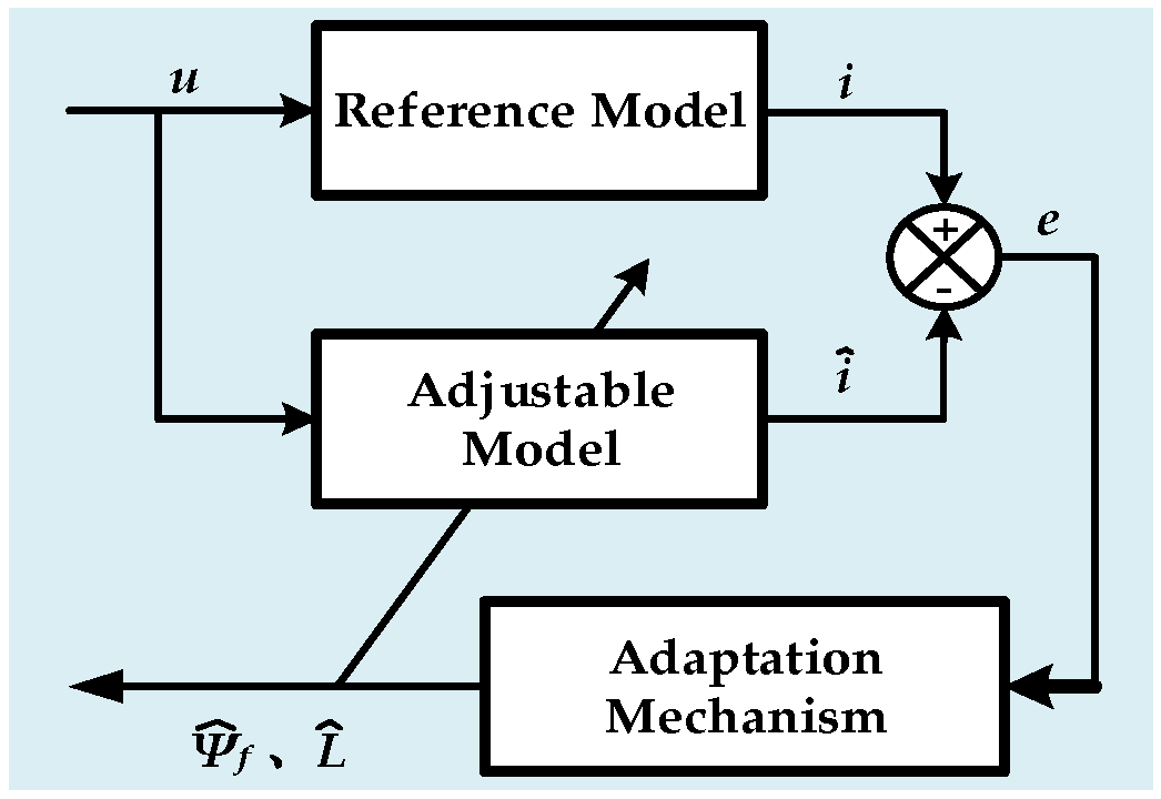
The MRAS is mainly composed of a reference model, an adjustable model, and an adaptation mechanism. The system block diagram of the MRAS is shown in Figure 1, where u is the input; i is the output of reference model; is the output of adjustable model; e is the error of i and ; and are estimated parameters, respectively.

Figure 1.
MRAS system block diagram.
The reference model is a state space equation containing the information of the parameters to be identified. According to the reference model, a model with the identified parameters as adjustable variables is established. The error, defined as the difference between the output of the reference model and that of the adjustable model, is sent to the adaptation mechanism to estimate the unknown parameters, which are fed back to the adjustable model. When the error between those two models converges to zero, the identified parameters are extraordinarily close to the true value. Here, Equation (2) is the reference model.
3.1. Adjustable Model
Since the inductance and flux linkage play an important role in high-performance vector control [9], it is necessary to identify the inductance and the flux linkage parameters when designing high-accuracy control law. An adjustable model is established by referencing Equation (2):
where , , , , , and are the estimated value of the d-axis and q-axis components of the stator current, respectively; and are the estimated value of the d-axis and q-axis components of the stator voltage, respectively; is the estimated value of the stator inductance; is the estimated value of the flux linkage.
3.2. State Space Equation of the Error
The state space equation of the error can be obtained by calculating the difference between the reference model (see Equation (2)) and the adjustable model (see Equation (3)). Then:
where . The system described by Equation (4) can be regarded as a feedback system, and its system block diagram is shown in Figure 2. In Figure 2, the dark blue part is a linear time-invariant forward channel , and the rest is a non-linear time-varying system that is used to calculate the variable .
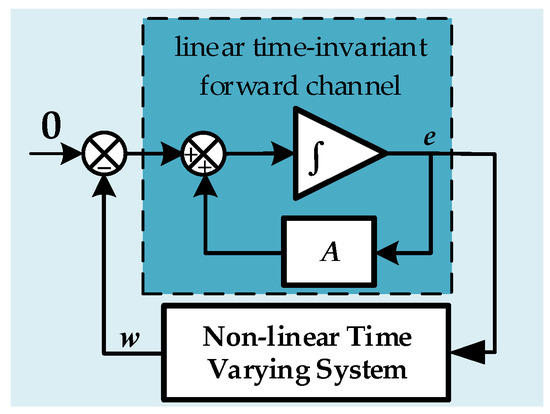
Figure 2.
Error of the state space equation system block diagram.
To make the system Equation (4) stable, i.e., converge to zero, Popov’s hyperstability theory is employed here. According to Popov’s hyperstability theory, two prerequisites are required to make Equation (4) asymptotically stable.
The first condition is the transfer function matrix of the linear time-invariant forward channel needs to be strictly positive and real. It is known from [8] that condition #1 holds when the inductances of d and q axes are equal.
The second one is the non-linear time-varying feedback link needs to satisfy Popov’s integral inequality, that is,
where and are the output and feedback quantity of the error state equation in Equation (4), respectively; is an arbitrary finite constant independent of time t.
Substituting Equation (4) into Equation (5), we have
where , , , ; and are arbitrary finite constants independent of time t, respectively.
3.3. Classical PI Adaptive Law
Here, the identification of the inductance parameters is taken as an example. Substituting the PI adaptive law into Equation (6), we have
where is the proportional gain; is the integral gain; is the nominal value of the reciprocal of the inductance. Equation (7) is Popov’s inequality of inductance identification based on the PI adaptive law, which satisfies the stability condition when the values of and are greater than zero [8]. By combining Equation (3) with Equation (7), it can be found that when the reference model voltage is invariable, Equation (3) is an integral series system with input and output , while Equation (7) is a zero-order linear system with input and output B(t). Therefore, an integral series system with input and output B(t) can be obtained. Its system structure is shown in Figure 3, where PI is controller; is the reciprocal of the estimated inductance; Equation (3) is the adjustable model; is the estimated current; U is the stator voltage.
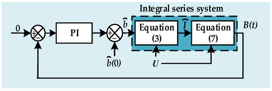
Figure 3.
Identification signal processing system block diagram.
The classical PI adaptive law has many advantages, such as simple parameter adjustment and fast response speed [21] but it cannot achieve a good anti-disturbance performance. Due to the proportional element, it is difficult to meet the balance between the tracking speed and the anti-disturbance performance. Therefore, it is necessary to determine a suitable to balance the response speed and the anti-disturbance performance, which is not an easy task.
4. ADRC Adaptive Law
4.1. ADRC Adaptive Law Design
To overcome the poor anti-disturbance performance of the classical PI adaptive law, an improved first-order linear ADRC adaptive law is proposed based on the premise that the controlled system is an integral series system, illustrated in Figure 3. Theoretically, the ADRC adaptive law has better anti-disturbance performance than the classical PI adaptive law.
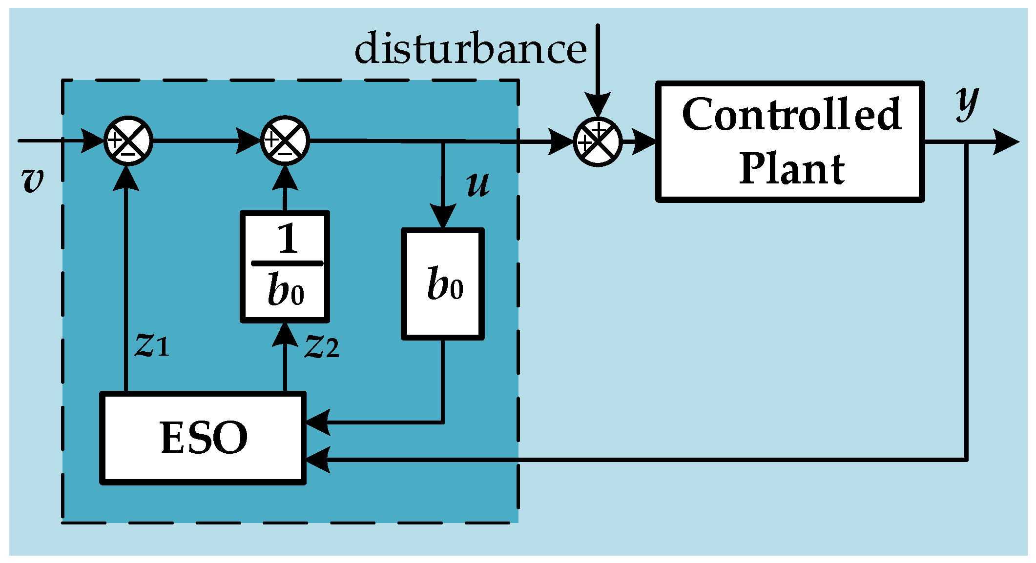
The structure of the first-order ADRC system is shown in Figure 4, where v is the reference; y is the feedback; u is the output of the controller; is the control gain; ESO is an extended state observer; is the estimation of v, is the estimation of disturbance.

Figure 4.
First-order ADRC system block diagram.
The mathematical description of the first-order linear ADRC:
where and are the gains of ESO; and generally, and ; is the bandwidth of the observer; is the tracking error. To balance the response speed and the anti-disturbance performance of the observer, the linear ADRC with a variable bandwidth is designed here, and the value of the bandwidth is set according to Equation (9).
where , , are different bandwidth values tuned according to the experience stated below; is the fixed value of error interval; n is a fixed value of multiples; is used to separate the observation error generated by noise. When is higher, the anti-disturbance performance will be better but the response speed will be lower. Through the variable bandwidth design, the response speed and anti-disturbance performance of the linear ADRC can be improved greatly.
From Equation (8), let the reference v be equal to 0, and the feedback y be equal to B(t) in Equation (7), Popov’s integral inequality of the inductance identification based on the ADRC adaptive law can be obtained:
The derivation process of Popov’s integral inequality of the flux linkage is the same as that of inductance, which is omitted here.
4.2. Stability Analysis of ADRC Adaptive Law
From Equation (8), the transfer function between the feedback y and the controller output u can be written:
Next, the inverse Laplace transform of Equation (11) can be applied:
Substituting Equation (12) into Equation (10), then:
where and are arbitrary finite constants independent of time, respectively.
It can be seen from Equation (13) that is greater than 0 and less than 1, so when and are greater than zero, Popov’s integral inequality holds. Therefore, it can be proved that the designed ADRC adaptive law satisfies Popov’s hyperstability conditions. Moreover, by introducing , the linear ADRC has low-pass characteristics, which can enhance the anti-high-frequency noise performance.
The derivation of the adaptive law of flux linkage identification and its stability proof are the same as those of inductance, which are also omitted here.
4.3. Frequency Domain Performance Analysis of ADRC Adaptive Law
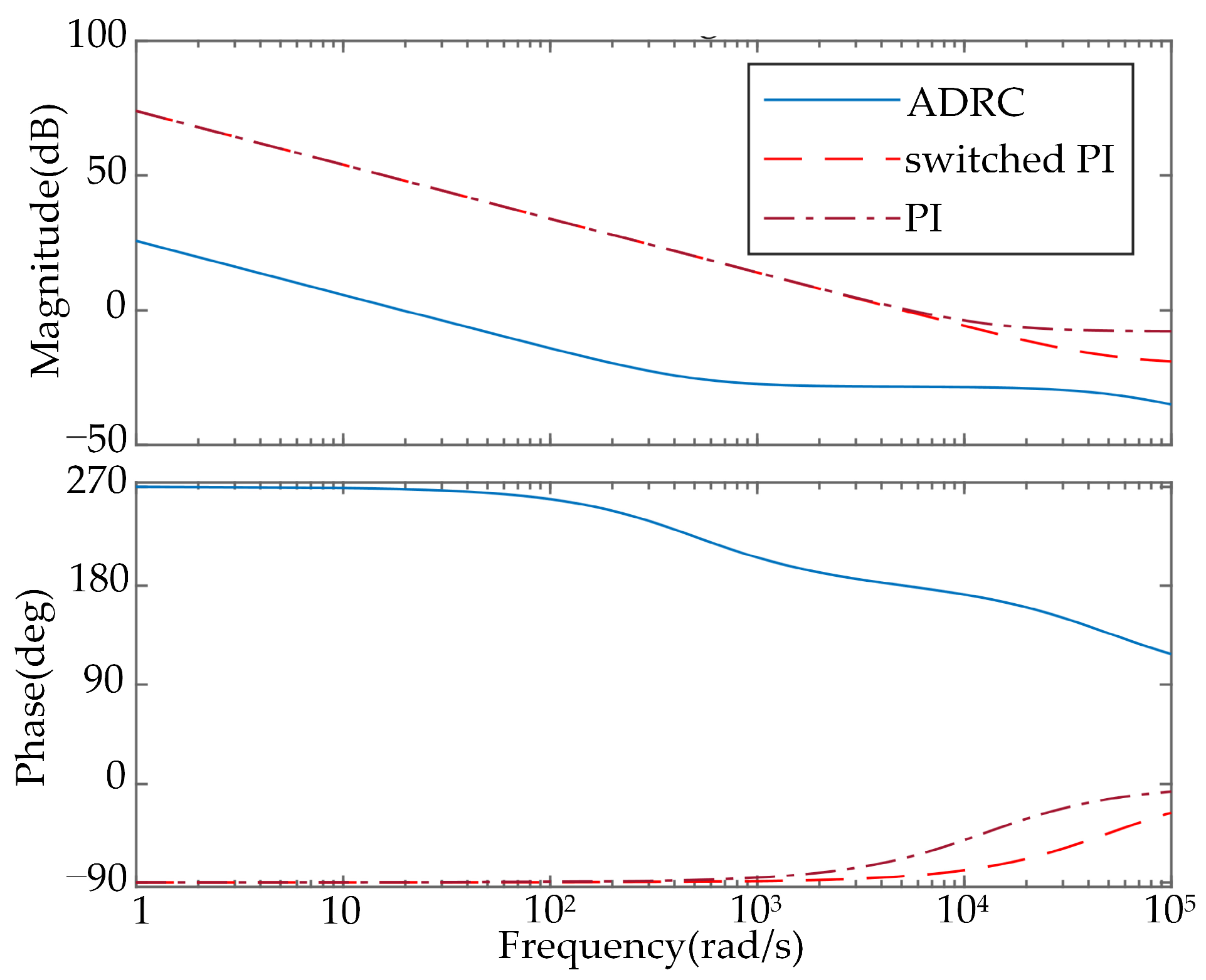
To exhibit the anti-high-frequency noise performance of the linear ADRC intuitively, the frequency domain performance is analyzed using the Bode diagram. In addition, the PI method and the switched PI method are also considered here for some comparative descriptions. The parameters of those three adaptive laws are set according to Table 1, Table 2 and Table 3.

Table 1.
Parameters of PI adaptive law.
Table 2.
Parameters of switched PI adaptive law.
Table 3.
Parameters of ADRC adaptive law.
The Bode diagram of those three adaptive laws is shown in Figure 5. The magnitude of switched PI and PI adaptive law in the high-frequency band is higher than that of the ADRC, which indicates that the anti-high-frequency noise performance of the ADRC is better than that of the switched PI and PI.
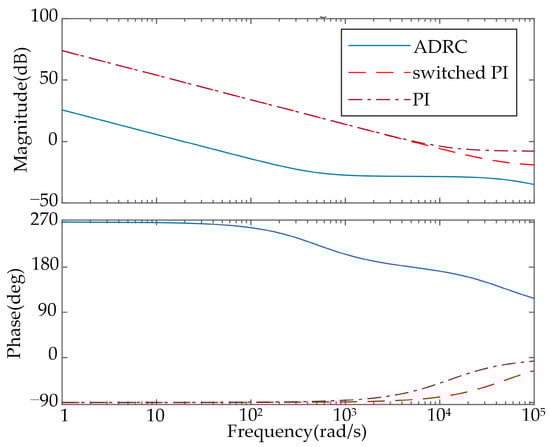
Figure 5.
Bode diagram of ADRC, switched PI and PI.
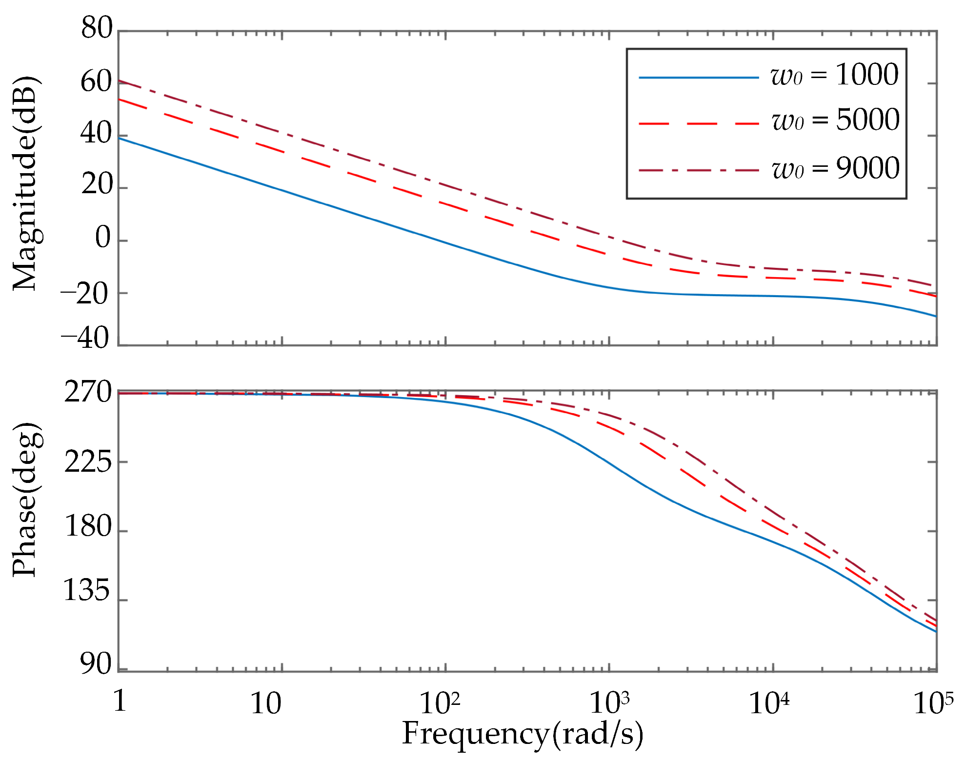
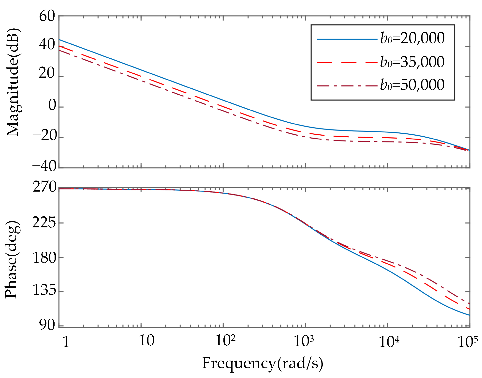
Bode diagrams of the ADRC under different parameter values are shown in Figure 6 and Figure 7. Obviously, the smaller the is, the better the filtering performance is, and the larger the is, the better the filtering performance is. Generally, when the bandwidth is higher, the response speed becomes faster but the anti-disturbance performance will decrease. To obtain better anti-disturbance performance and quicker response speeds, in Equation (9) are set according to the following: is usually smaller and are set much larger. For example, when the identified parameter is about 5 × 10⁻³, can be taken from 20,000 to 30,000, and can be taken from 1000 to 4000. When the control gain is higher, the response speed will decrease but the anti-disturbance performance will be better. Usually, the value of is about 30,000 to 60,000.

Figure 6.
Bode diagram of ADRC with different bandwidths.
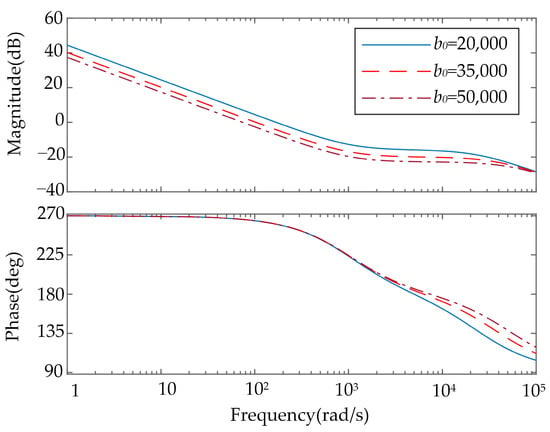
Figure 7.
Bode diagram of ADRC with different control gains.
4.4. SPMSM Control System
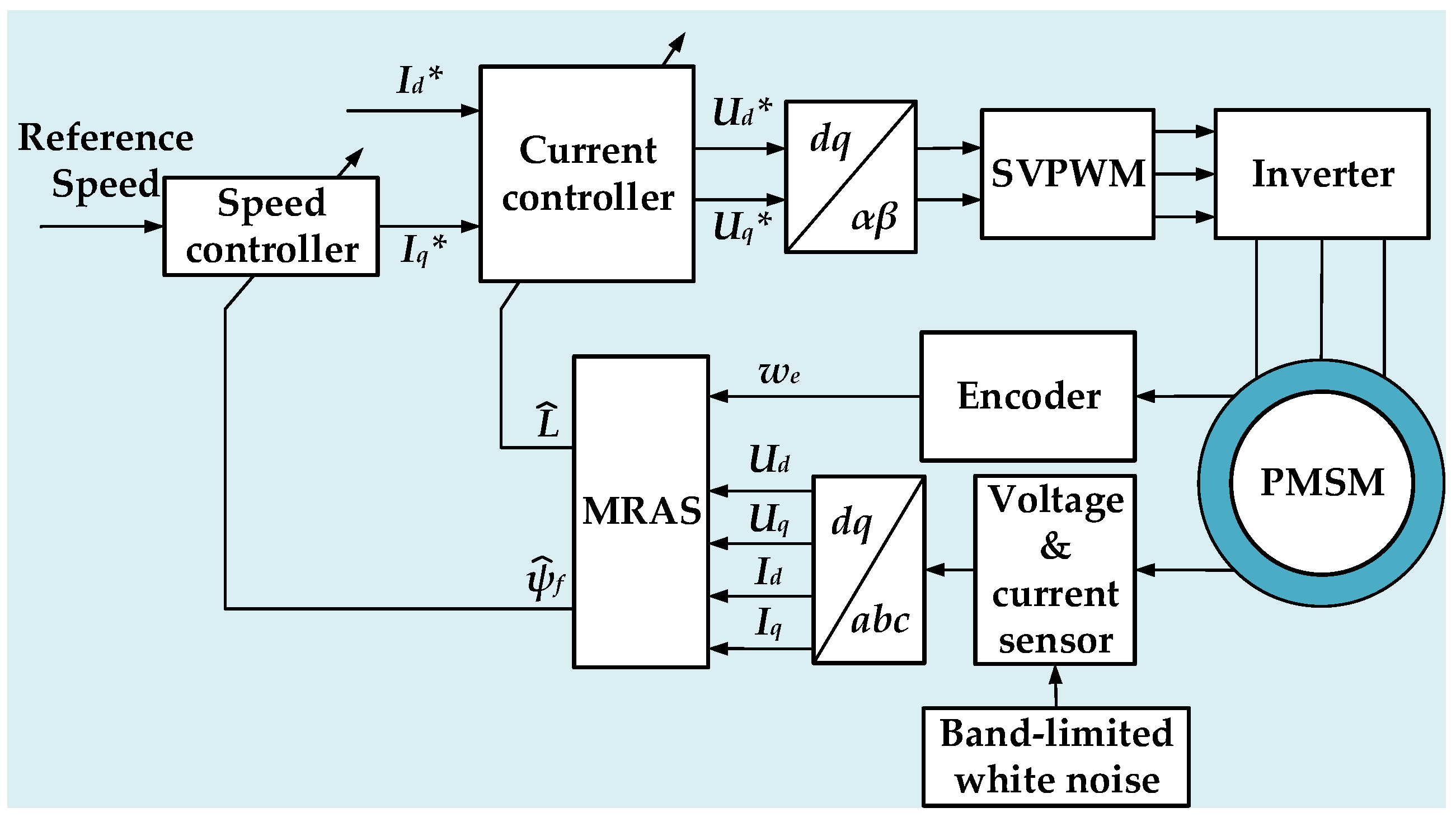
In this paper, a double closed-loop structure of the speed and current control system of SPMSM is designed so that the control mode of the current loop is = 0. The structure of the control system with parameter identification is shown in Figure 8, where , , , are the reference values of , , , , respectively. The first-order ADRC is employed for the speed and current controllers. The gain parameters of the controller are tuned according to [22]. The control gain of the speed and current controllers are set to and , respectively, and the online identification results of inductance and flux linkage in the MRAS are sent back to the current and speed controller to update the control gain in real-time.
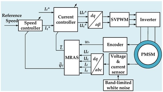
Figure 8.
The block diagram of the SPMSM control system.
5. Simulation Verification
In this paper, the simulation experiments are carried out on MATLAB/Simulink ver.2020 software. The simulation experiments consist of two parts: One is a set of contrast experiments to illustrate the superior quality of the proposed identification method. The other is the comparative results of the SPMSM speed regulation using the parameters identified by different methods.
Here, the noises of the voltage and current sensor are generated by the band-limited white noise module of Simulink. The sampling time of the white noise module is set to 1 × 10⁻⁵, and the noise intensity is set to 1 × 10⁻¹⁰. The noise intensity is set to be the square of the signal amplitude multiplied by the average of the sampling time. Therefore, when the sampling time is set to 1 × 10⁻⁵ and the noise intensity is 1 × 10⁻¹⁰, the average amplitude of the noise signal should be calculated to be 1 × 10−2.5.
Except for the parameters to be identified, the other motor parameters are all real values shown in Table 4.
Table 4.
Parameters of SPMSM.
5.1. Simulation of Flux Identification
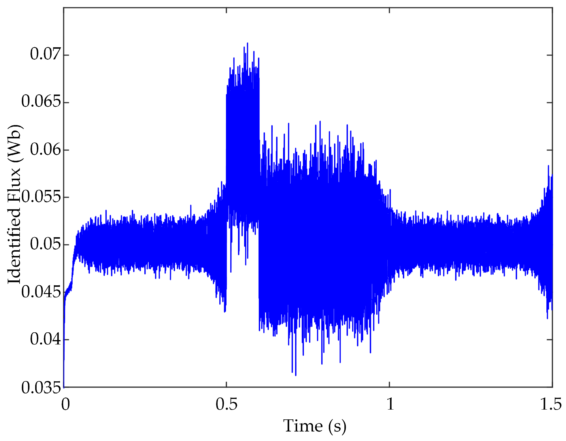
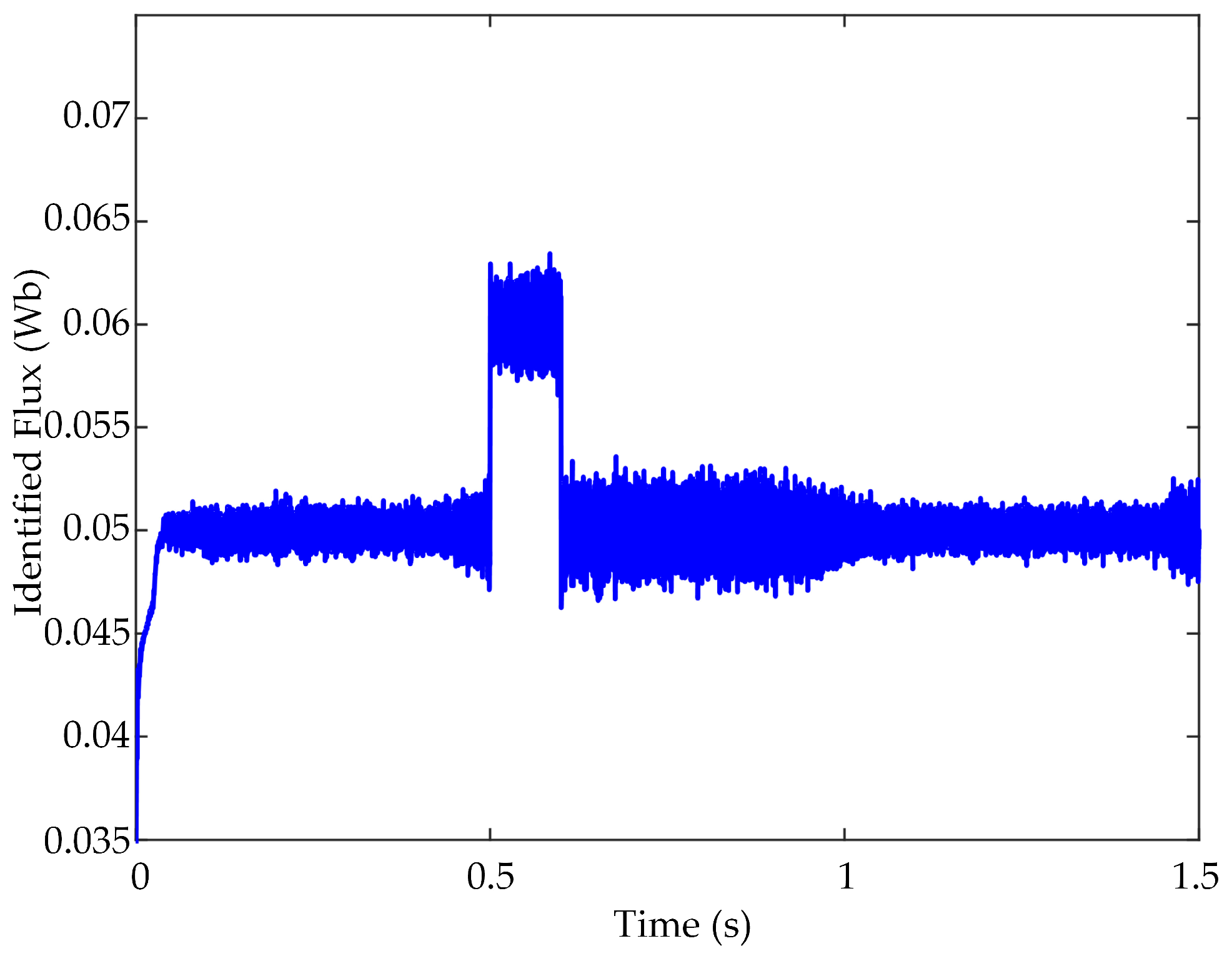
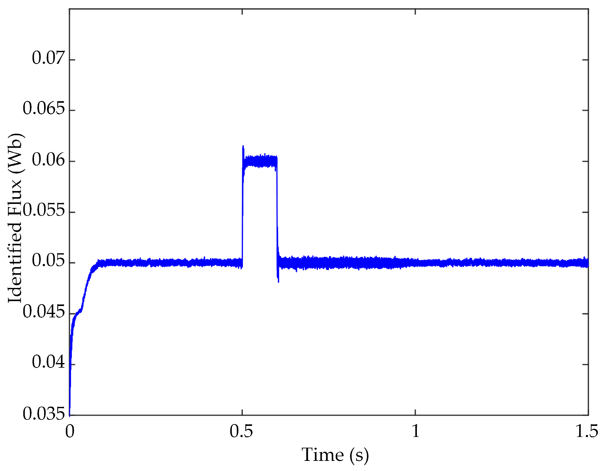
For the online identification of the flux linkage, three different adaptive laws are chosen for comparative simulation. To verify the dynamic identification performance, the real flux linkage is set to increase by 20% at 0.5 s and restore the original value at 0.6 s. The results are shown in Figure 9, Figure 10 and Figure 11. From Figure 9 and Figure 10, the adaptive laws based on PI and switched PI are greatly affected by noise and show an unsatisfactory performance. From Figure 11, the fluctuation amplitude of the flux linkage is much smaller, which displays that the identification accuracy of ADRC adaptive law is superior to the other two methods. In addition, the tracking speed of the ADRC adaptive law is as quick as the PI and the switched PI.

Figure 9.
PI adaptive-law-based flux identification result.
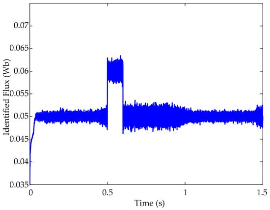
Figure 10.
Switched PI adaptive-law-based flux identification result.
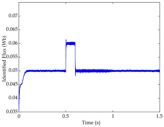
Figure 11.
ADRC adaptive-law-based flux identification result.
In addition, from 0.5 s to 1 s, the PMSM runs at a faster speed. According to Equation (6), the flux linkage identification is closely related to the electromechanical angular velocity of the PMSM. Theoretically, the identification of the flux linkage will be greatly affected by the PMSM speed. In fact, it is also true. From Figure 9 and Figure 10, when using the switched PI and PI adaptive law, the identification accuracy is obviously affected by the PMSM speed. From Figure 11, the ADRC adaptive law can effectively suppress the chattering benefit from its strong anti-interference ability.
5.2. Simulation of Inductance Identification
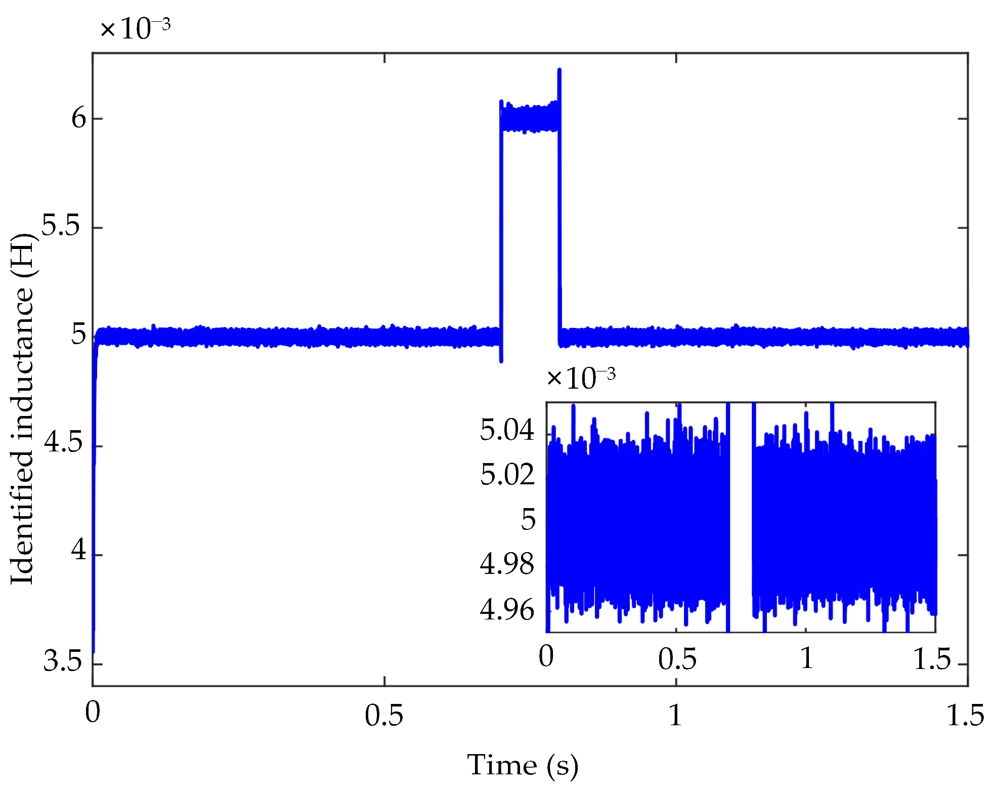
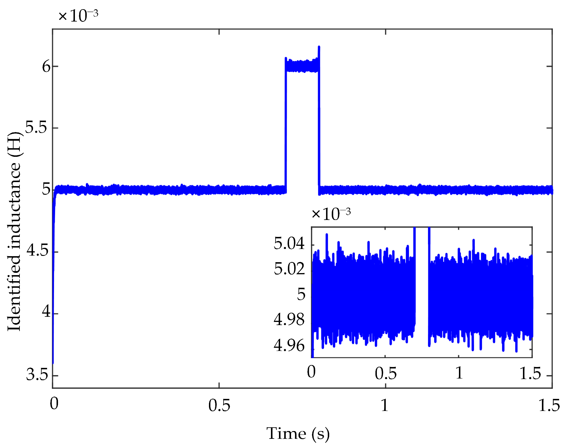
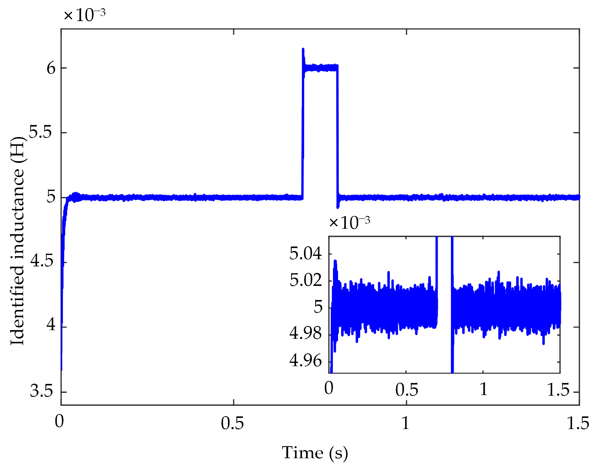
For identification of the inductance, to verify the dynamic identification performance, the real inductance is also set to increase by 20% at 0.6 s and restore the original value at 0.7 s. The identification results are shown in Figure 12, Figure 13 and Figure 14. From Figure 12, Figure 13 and Figure 14, the identification process of the ADRC adaptive law has the same response speed as the PI and the switched PI. The fluctuation amplitude of the identified inductance based on ADRC adaptive law is much smaller. The width of the fluctuation amplitude of the ADRC adaptive law is about 0.02 × 10⁻³, while the values of the PI and the switched PI are 0.04 × 10⁻³ and 0.03 × 10⁻³, respectively.
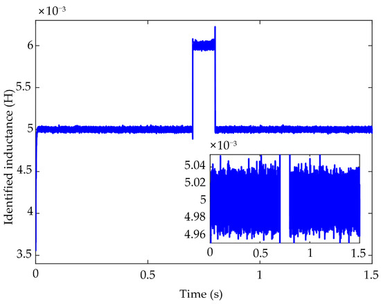
Figure 12.
PI adaptive-law-based inductance identification result.
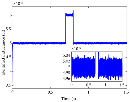
Figure 13.
Switched PI adaptive-law-based inductance identification result.
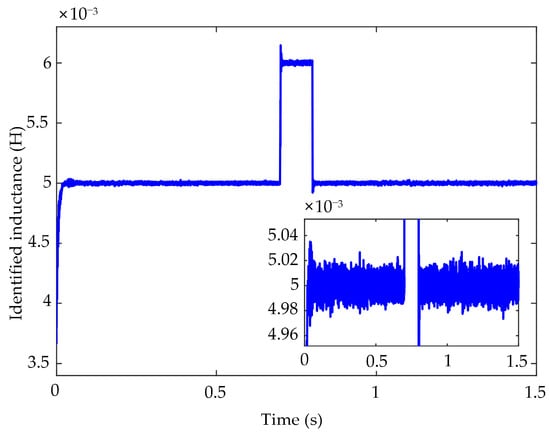
Figure 14.
ADRC adaptive-law-based inductance identification result.
5.3. Simulation of SPMSM Speed Regulation
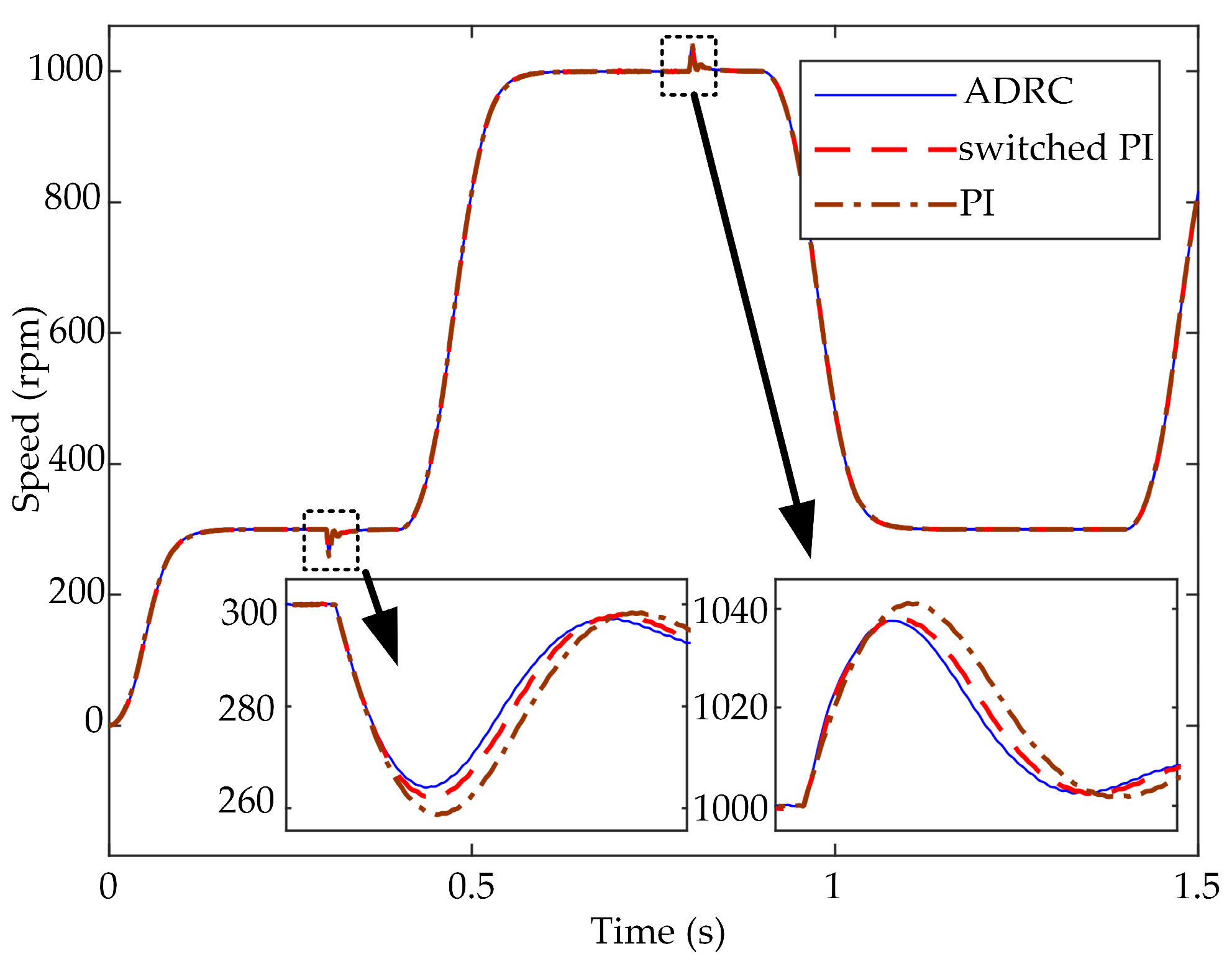
To illustrate the important role of the proposed parameter identification algorithm when designing the high-performance controller, the simulation experiment of motor speed regulation is carried out based on the double closed-loop control system described in Figure 8. The given speed is periodically adjusted between 300 rpm and 1000 rpm, and the motor torque load is set to increase by 5 N.m at 0.4 s and restores the original value at 0.9 s. Three adjustable laws based on ADRC, switched PI, and PI are considered for the MRAS, and the speed regulation results are shown in Figure 15.
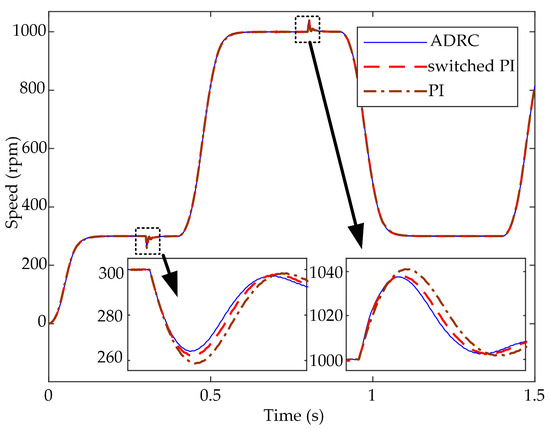
Figure 15.
SPMSM speed comparison diagram.
From Figure 15, when the motor torque load changes suddenly at 0.4 s and 0.9 s, the speed curve under the ADRC adaptive law has a relatively low-speed drop, and the speed curves of the switched PI and PI adaptive laws have more obvious fluctuations than that of the ADRC adaptive law. Obviously, the proposed adaptive law based on ADRC has better anti-disturbance performance than the switched PI and classical PI adaptive laws.
6. Conclusions
The existence of high-frequency noise brings great challenges when using the MRAS to identify the unknown parameters of the PMSM. Therefore, a variable-bandwidth linear ADRC adaptive law is proposed for the MRAS to enhance the anti-disturbance performance and improve the identification accuracy. By designing a variable bandwidth for the linear ADRC, its anti-disturbance ability is significantly improved while ensuring the response speed. Finally, some simulation experiments are designed to verify the performance of the proposed method. The results exhibit that the MRAS based on the variable-bandwidth linear ADRC adaptive law has good identification accuracy and anti-disturbance ability. In addition, facing the mutation of the identified parameters, it also exhibits a fast response speed under the premise of identification accuracy. Moreover, the experimental results of the double closed-loop control system designed in this study illustrate that the proposed MRAS can be used for high-performance controllers.
Theoretically, the proposed ADRC adaptive-law-based MRAS can be implemented on a motor. However, the actual performance of MRAS will be limited by the operational performance of DSP. Since the interruption frequency of DSP is lower than the sampling step of the simulation, the response speed and identification effect of the parameters on the physical platform might not perform as well as those in the simulation. In the future, physical experiments will be carried out to verify the performance of the proposed method. A better identification effect is expected to serve for the high-performance controller design.
Author Contributions
Writing—review and editing, X.Q. and C.S.; supervision, C.S., Y.G., T.S. and H.W. All authors have read and agreed to the published version of the manuscript.
Funding
This research was funded by the National Natural Science Foundation of China, grant no. 62273213, 62073199, 62103245, 62203280; the Natural Science Foundation of Shandong Province for Innovation and Development Joint Funds, grant no. ZR2022LZH001; the Natural Science Foundation of Shandong Province, grant no. ZR2020MF095, ZR2022MF341; the Taishan Scholarship of Construction Engineering.
Institutional Review Board Statement
Not applicable.
Informed Consent Statement
Not applicable.
Data Availability Statement
This article does not use a dataset, and all the required parameter data are provided in the article.
Conflicts of Interest
The authors declare no conflict of interest.
References
- Liu, Z.; Feng, G.; Han, Y. Extended-Kalman-Filter based magnet flux linkage and inductance estimation for PMSM considering magnetic saturation. In Proceedings of the Youth Academic Conference of Chinese Association of Automatic (YAC), Guangzhou, China, 28–30 May 2021. [Google Scholar]
- Deng, W.; Xia, C.; Yan, Y.; Geng, Q.; Shi, T. Online Multiparameter Identification of Surface-Mounted PMSM Considering Inverter Disturbance Voltage. IEEE Trans. Energy Convers. 2016, 32, 202–212. [Google Scholar] [CrossRef]
- Sun, P.; Ge, Q.; Zhang, B.; Wang, X. Sensorless control technique of PMSM based on RLS on-line parameter identification. In Proceedings of the 2018 21st International Conference on Electrical Machines and Systems (ICEMS), Jeju, Korea, 7–10 October 2018. [Google Scholar]
- Shi, Z.; Wang, Y.; Ji, Z. Bias compensation based partially coupled recursive least squares identification algorithm with forgetting factors for MIMO systems: Application to PMSMs. J. Frankl. Inst. 2016, 353, 3057–3077. [Google Scholar] [CrossRef]
- Xu, D.; Zhang, S.; Liu, J. Very-low speed control of PMSM based on EKF estimation with closed loop optimized parameters. ISA Trans. 2013, 52, 835–843. [Google Scholar] [CrossRef] [PubMed]
- Li, X.; Kennel, R. General Formulation of Kalman-Filter-Based Online Parameter Identification Methods for VSI-Fed PMSM. IEEE Trans. Ind. Electron. 2021, 68, 2856–2864. [Google Scholar] [CrossRef]
- Zhao, J.; Wang, L.; Xu, L.; Dong, F.; Song, J.; Yang, X. Uniform Demagnetization Diagnosis for Permanent-Magnet Synchronous Linear Motor Using a Sliding-Mode Velocity Controller and an ALN-MRAS Flux Observer. IEEE Trans. Ind. Electron. 2022, 69, 890–899. [Google Scholar] [CrossRef]
- Khlaief, A.; Boussak, M.; Châari, A. A MRAS-based stator resistance and speed estimation for sensorless vector controlled IPMSM drive. Electr. Power Syst. Res. 2021, 36, 1903–1906. [Google Scholar] [CrossRef]
- Liu, Z.-H.; Wei, H.-L.; Li, X.-H.; Liu, K.; Zhong, Q.-C. Global Identification of Electrical and Mechanical Parameters in PMSM Drive Based on Dynamic Self-Learning PSO. IEEE Trans. Power Electron. 2018, 33, 10858–10871. [Google Scholar] [CrossRef]
- Liu, K.; Zhu, Z.Q. Quantum Genetic Algorithm-Based Parameter Estimation of PMSM Under Variable Speed Control Accounting for System Identifiability and VSI Nonlinearity. IEEE Trans. Ind. Electron. 2014, 62, 2363–2371. [Google Scholar] [CrossRef]
- Kashif, M.; Singh, B. Modified Active-Power MRAS Based Adaptive Control with Reduced Sensors for PMSM Operated Solar Water Pump. IEEE Trans. Energy Convers. 2022, 38, 38–52. [Google Scholar] [CrossRef]
- Hamed, H.; Elbarbary, Z.; Moursi, M. A new δ-MRAS method for motor speed estimation. IEEE Trans. Power Deliv. 2021, 36, 1903–1906. [Google Scholar] [CrossRef]
- Benlaloui, I.; Drid, S.; Chrifi-Alaoui, L.; Ouriagli, M. Implementation of a New MRAS Speed Sensorless Vector Control of Induction Machine. IEEE Trans. Energy Convers. 2014, 30, 588–595. [Google Scholar] [CrossRef]
- He, Y.; Wang, J.; Wang, Z.; Wang, H.; Wang, Q.; Wei, D.; Zeng, Z. Speed observation of high speed permanent magnet synchronous motor based on fuzzy MRAS. In Proceedings of the Chinese Control Conference, Shenyang, China, 27–29 July 2020. [Google Scholar]
- Ben Azza, H.; Zaidi, N.; Jemli, M.; Boussak, M. Development and Experimental Evaluation of a Sensorless Speed Control of SPIM Using Adaptive Sliding Mode-MRAS Strategy. IEEE J. Emerg. Sel. Top. Power Electron. 2014, 2, 319–328. [Google Scholar] [CrossRef]
- Ahmed, W.A.E.M.; Adel, M.M.; Taha, M.; Saleh, A.A. PSO technique applied to sensorless field-oriented control PMSM drive with discretized RL-fractional integral. Alex. Eng. J. 2021, 60, 4029–4040. [Google Scholar] [CrossRef]
- Amin, M.M.; El-Sousy, F.F.M.; Mohammed, O.A.; Aziz, G.A.A.; Gaber, K. MRAS-Based Super-Twisting Sliding-Mode Estimator Combined with Block Control and DTC of Six-Phase Induction Motor for Ship Propulsion Application. IEEE Trans. Ind. Appl. 2021, 57, 6646–6658. [Google Scholar] [CrossRef]
- Liu, Z.-H.; Nie, J.; Wei, H.-L.; Chen, L.; Li, X.-H.; Lv, M.-Y. Switched PI Control Based MRAS for Sensorless Control of PMSM Drives Using Fuzzy-Logic-Controller. IEEE Open J. Power Electron. 2022, 3, 368–381. [Google Scholar] [CrossRef]
- Khan, M.; Islam, R.; Iqbal, J. Control strategies for robotic manipulators. In Proceedings of the International Conference on Robotics and Artificial Intelligence (ICRAI), Rawalpindi, Pakistan, 25 May 2012. [Google Scholar]
- Wang, S.; Gan, H.; Luo, Y.; Wang, X.; Gao, Z. Active disturbance rejection control with fractional-order model-aided extended state observer. ISA Trans. 2023; in press. [Google Scholar]
- Iqbal, U.; Samad, A.; Nissa, Z.; Iqbal, J. Embedded control system for AUTAREP—A novel AUTonomous articulated robotic educational platform. Tech. Gaz. 2014, 21, 1255–1261. [Google Scholar]
- Sun, B.; Wang, H.X.; Su, T.; Sheng, C.Y.; Lv, X.R. Nonlinear active disturbance rejection controller design and tuning for Permanent Magnet Synchronous Motor speed control system. Proc. CSEE 2020, 40, 6715–6725. [Google Scholar]


Disclaimer/Publisher’s Note: The statements, opinions and data contained in all publications are solely those of the individual author(s) and contributor(s) and not of MDPI and/or the editor(s). MDPI and/or the editor(s) disclaim responsibility for any injury to people or property resulting from any ideas, methods, instructions or products referred to in the content. |
© 2023 by the authors. Licensee MDPI, Basel, Switzerland. This article is an open access article distributed under the terms and conditions of the Creative Commons Attribution (CC BY) license (https://creativecommons.org/licenses/by/4.0/).