Article

Application of Additive Manufacturing Technology for Chair Parts Connections

by
Antoniu Nicolau
1,
Mihai Alin Pop
2,
Sergiu Valeriu Georgescu
1 and
Camelia Coșereanu
1,*
1
Faculty of Furniture Design and Wood Engineering, Transilvania University of Brasov, B-dul Eroilor, nr. 29, 500036 Brasov, Romania
2
Faculty of Materials Science and Engineering, Transilvania University of Brasov, B-dul Eroilor, nr. 29, 500036 Brasov, Romania
*
Author to whom correspondence should be addressed.
Appl. Sci. 2023, 13(21), 12044; https://doi.org/10.3390/app132112044
Submission received: 25 September 2023 / Revised: 23 October 2023 / Accepted: 30 October 2023 / Published: 4 November 2023

Abstract

:
Additive manufacturing (AM) is a potential technology to be applied for replacing wood joints in the furniture industry. Overall, 3D-printed connectors have a lot of advantages in chair construction: the possibility of improving the design by using colored materials and new concepts with no limits of shape and size, avoiding the use of synthetic materials such as adhesives and finishing materials. The present research shows the results of the research conducted on 3D-printed connectors for a chair leg-stretchers joint. Larch (Larix decidua Mill.) wood was used for chair components and selective laser sintering (SLS) technology was employed for the 3D-printing connector designed to assemble the chair elements. Diagonal tensile and compression tests were performed on the L-type joints with 3D-printed connectors and the bending moments were determined and compared to the results obtained after testing the leg-stretchers mortise–tenon joints made of larch wood, taken as a reference. Micrograph investigation was finally performed on the broken areas of the 3D-printed connectors as a result of mechanical testing failures. The results show that the SLS printing technology applied to build the connector does not ensure enough strength to the assembly, and changes in printing parameters are needed for further research, in terms of laser power and scan speed.

1. Introduction

Nowadays, additive manufacturing (AM) is gaining more and more attention in the industrial field for rapid prototyping, rapid manufacturing, mass customization and mass production [1]. Based on CAD modelling, this technology is supported by a diversity of professional software able to create bold shapes, with no limits of creativity and has the potential to transform new ideas and methods outside of ‘conventional’ industry norms [2].
One of the methods applied in additive manufacturing is selective laser sintering (SLS). Powder raw material, such as nylon, bio-plastics, ceramics, wax, bronze, stainless steel, cobalt chrome and titanium, is sintered or fused by the application of a laser beam for each layer specified by the 3D model [1,3,4]. The minimum layer thickness for this technology is 0.1 mm and the advantage of applying this method is the fast build speed, but the quality of the surface is appreciated as an average one [4]. According to the findings in the literature, the process input parameters, such as scanning rate, laser power, hatching distance or scanning pattern, can cause defects in the structure of the printed part or an insufficient density of the sintered material [5]. During the SLS processing, sintered, semi-sintered/semi-melted or completely melted surfaces can be formed [6]. The most important factor affecting the quality of the SLS printed surfaces is the scanning pattern, varying from the raster in X or Y direction, alternating in the X and Y direction, spiral, fractal, or scanning of successive sectors [5]. Applying a raster in alternating in the X and Y direction resulted in a higher fractional density comparing to the use of the raster strategy in the X or Y direction [7]. On the other hand, the particle fusion can be improved by high energy density, with a benefit on the mechanical properties of the final part. The energy radiated into the powder bed produces the melting and the layers adhesion, so the higher the energy, the better the connection between the two successive sintered layers, and the sintered part can be generated without layer delamination [8].
Despite its advantages, the ability of SLS to process polymers is affected by some defects, such as the porous structure and balling effect [6,9]. The causes of these defects were found to be the high laser power and the fast scan speed and interruptions near fused powders. The balling defect affects the uniformity of the powder layer deposited on the previously sintered one and often leads to cracks, porosity and a rough surface [9]. Another particularity of this technology is that the final product needs a long cooling time and also, the non-fused powder remaining on the part exterior surface has to be removed.
Accompanying the Industry 4.0 digital revolution, additive manufacturing (AM) is considered a key technology [10]. At first being applied for fast prototyping in medicine, aerospace and automotive industry, it became rapidly widespread in other sectors, including the furniture industry. There are three types of applications where 3D-printing technology is used in furniture manufacturing, as follows: the entire piece of furniture is manufactured in 3D printing, some parts of the furniture are 3D printed, or only connection parts or fasteners are produced using this technology.
The variety of materials available today for AM and the corresponding 3D-printing technologies and printers are the source of inspiration for freedom design with complex geometries. In the furniture industry, the most used materials are thermoplastic materials in the form of filaments, used in the case of applying fused filament fabrication (FFF), or fused deposition modeling (FDM) [10,11,12,13,14], and thermoplastic powders, used when applying selective laser sintering (SLS) technology [10]. PLA and ABS are the most commonly used materials to manufacture the filaments for AM in furniture manufacturing, but they are confronted with several drawbacks: PLA has a poor toughness, whilst the ABS is damaged by sunlight [15], for which reasons various composite materials are being developed to replace them [16,17]. In addition to the above remarks, another drawback of FFF technology is that for highly complex parts, printing supports are necessary, which in certain cases are either difficult or even impossible to remove. Instead, SLS is an expensive technology but has the advantage of using a large variety of materials comprised in thermoplastic, ceramic, glass or metal powders, and has no limitations in producing geometrically complex parts for artistic purposes and pieces of furniture without using supports [18]. The powder that is not melted by the laser beam behaves like the supports made with FFF technology, only it is easily removed by brushing or blowing with air. Depending on the needs of the product designer, if you only want a quick check of the shape and the physical-mechanical properties are not very important, then FFF technology is chosen, and if you want a prototype with good properties, high precision, etc., and even if the time to obtain it is longer (compared to FFF technology—but lower than by other classic methods) then SLS technology can be chosen [19]. Using SLS technology, it is possible to realize microstructures at the scale of tens of microns and based on the elastic behavior of the aperiodic microstructures inspired by Voronoi open-cell foams, large objects can be generated with specific elasticity [20,21,22], including furniture parts or connectors.
L-type corner joints for furniture are tested for bending strain, in the case of chairs [23], or case furniture [24,25,26]. The bending moment is calculated, depending on the test type, namely a tensile or compression test. Tests were performed on chair solid wood parts [23,27], or wood-based panels [24,25]. Wood dowels [24,27], dowels and innovative fasteners made from polyamide and obtained by 3D printing using the SLS technology [24,26] were used for jointing the panels. The strength of the corner joints connected with the wood dowels was proved to be significantly higher than those connected with the 3D-printed dowels [24]. In order to test the strength and stiffness of the L-type corner joints, both for solid wood and wood-based panels, two methods are applied in the literature, namely the diagonal compression and the diagonal tensile test, respectively [11,23,24,25]. A chair was built with 3D-printed connectors designed for chair leg and side rails jointing, made from ABS filament by using the FDM-printing technology [28]. The wooden parts were made of beech wood, and connectors with wall thicknesses of 3 mm and 5 mm, respectively, were bonded with the wooden parts with a polyurethane adhesive. Average failure forces for the connectors (in the range of 790 N–905 N) and for the wood mortise-and-tenon joints (1769 N) were recorded, showing the mechanical performance of the connectors at the level of at most 51% of the mechanical performance of the traditional wooden jointing.
The present research investigates the quality and the strength and stiffness of the 3D-printed connectors designed to assemble the leg and two stretchers of a chair. The proposed 3D-printing method in the research is SLS technology and the material used for 3D printing is Polyamide 12 (PA12). The assembly composed of connector and chair components forms an L-type corner joint. Both a diagonal compression test and a diagonal tensile test were performed on the assembled parts and the bending moment was calculated. The results were compared to those of the reference assembly, made of larch solid wood components assembled by a glued mortise and tenon joint.
The use of a 3D-printed connector instead of a classical wood joint brings the advantage of removing from the technological process several operations, such as machining and gluing the mortise–tenon joint, conditioning time for bonded parts, and also contributes to the reduction in solid wood consumption needed for the chair components. All these processing operations are time and cost consuming. In addition to this, jointing with 3D connectors provides a one-time ready-to-assemble (RTA) construction of the chairs and implicitly the ease of assembly. They also allow free design with complex geometrical structures, a multitude of colors and a high surface roughness when using the SLS technology.
The literature in the field provides various models of 3D-printed fasteners and connectors made of different materials; for each strength and stiffness, corner joints were studied and resulted in a low performance compared to the traditional wooden joints. The challenges in the use of SLS technology for connectors and fasteners need more study to optimize the printing parameters and to predict the defects, such as the porous structure. The results obtained thus far in this field represent a starting point for modeling the shape and dimensions of the connectors and fasteners, so as to improve their mechanical properties.
The present research is a contribution to the use of PA12 material and SLS technology as a future perspective for jointing the wooden components of chairs, and bringing novelty in their design and assembly method. Previous research employed FDM and FFF technology for the 3D-printed connectors used for jointing the chair elements, but the SLS technology is preferred because the quality of the parts is clearly superior, no supports are required for complex parts and any geometric shape can be obtained without restrictions. By assessing the results of bending moments under the tensile and compression loads and the defects occurring after testing, the present study aims to offer input data to build a safe and solid chair structure using 3D-printed connectors.

2. Materials and Methods

2.1. Materials

The wooden components of the experimental samples consisted of one leg part and two stretcher parts were made from larch wood (Larix decidua Mill.), the material used to manufacture a set of chairs in the frame of Faculty of Furniture Design and Wood Engineering at Transylvania University of Brasov. The objective of the research is to replace the classical mortise–tenon joint between the leg and stretcher with the 3D-printed connector designed for this purpose. The classical mortise–tenon joint and the dimensions of the sample used in the experiment as a reference one are presented in Figure 1a, and the chair assembled parts using the designed connector are presented in Figure 1b.
As seen in Figure 1a, the sizes of the piece of the leg in the assembly was 50 mm × 35 mm × 35 mm, and the sizes of the stretcher including the tenon were 222 mm × 35 mm × 22 mm, and without tenon were 210 mm × 35 mm × 22 mm. The larch wood had a moisture content of 9.2%. A tight fit was used between the wooden parts and connector. Mortise and tenon were glued with commercial polyvinyl acetate Novobond D2.
The material selected to be used for 3D printing with SLS technology is DuraForm PA Plastic powder manufactured by 3D Systems, 2nd Floor, West and South Wings, The Maylands Building, 200 Maylands Avenue, Hemel Hempstead, Hertfordshire. HP2 7TG, United Kingdom. The characteristics of this material, according to the technical sheet of the material, are presented in Table 1.

2.2. 3D Printing

The software used to design the 3D model is SolidWorks 3D CAD, version 2016 developed by Dassault Systèmes, France. The file .STL type was imported in the software of SPRO 60 SD printer. The installation assists the manufacturing of products made of ceramic, metallic and polymeric or composite powders, regardless of their geometrical complexity. The sintering furnace attached to the SLS installation sinters the ceramic and metallic powders, and according to the desired specifications, their infiltration with different metals. The maximum dimensions for the specimen can be 315 × 315 × 415 mm.
The SLS technology used for 3D printing the connectors uses a high-power laser beam, which, by melting (sintering) powder in alternating layers, leads to obtaining the desired 3D model. The 3D model is initially converted into cross-sections and then sent to the printer. Based on the information received, the moving laser beam selectively melts (sinters) the powder layer on the build platform, according to each cross-section. The following parameters were used for 3D printing the experimental connectors: fill laser power of 16 W, outline laser power of 12 W, 1 for outline scan count, slicer fill scan spacing of 0.15 mm, and 1 for sorted fill enabled. It was applied to the raster alternating in the X and Y direction in order to obtain a high density, as recommended in the literature [7]. The position of printing the connector is shown in Figure 2.
The deposition of the successive powder layers measures between 20 μm and 150 μm [5]. The microscopic images taken with 200× magnification show the sizes of the particles of the new powder (Figure 3), measuring up to 100 μm.
In the present research, new powder has been used, and according to the image in Figure 3, the sizes of the particles varied from about 20 μm to 100 μm, and the height of each sintered layer by the laser beam is 100 μm (Figure 4). In case of the used powder, the non-fused powder is removed after the specimen is 3D printed. In Figure 4, there is a schematic representation of the sintering process by laser beam. The red area is the scanned area by the laser beam. A part of the particle, as seen in the detail (left), was sintered, whilst the rest remained unfused and was removed and reused.

2.3. Microscopic Investigation

Microscopic investigation of the PA12 powder and of the 3D-printed connectors before and after mechanical testing was conducted using the optical microscope from Nikon OmniMet-Buehler (Tokyo, Japan). The magnification power used to investigate the powder and the defects occurring in the connectors after their mechanical testing was of 100×, and 200×, respectively. Longitudinal and crosscut sections of the connectors were investigated, in order to evaluate the cracks and ruptures occurring due to the tensile and compression loads applied during the tests on the leg-stretches assembly.

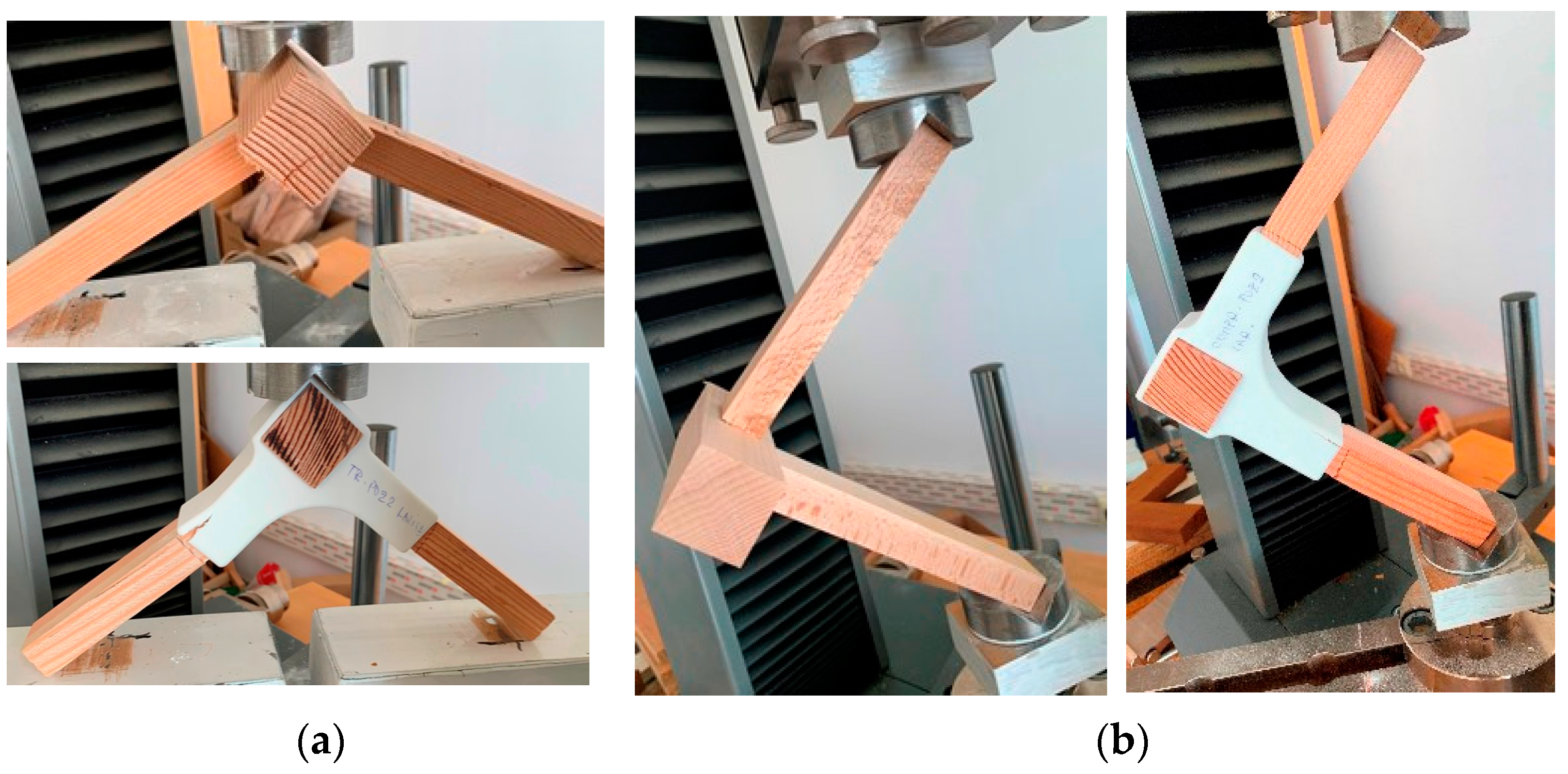
2.4. Mechanical Tests

The L-type corner joint specimens were tested under both diagonal compression and tensile tests, using the models described in the literature [23,24,25]. The tests were performed on a Zwick/Roell Z010 universal testing machine (Ulm, Germany) for six samples of each category. The compressive forces tend to open the joint, while the tensile forces tend to close the joint and bending moments occur at the corner joints under these loads [24]. The model and the equations used to calculate the bending moment under the tensile load (Mt) and under the compression load (Mc) are all presented in Figure 5. In these equations, F represents the maximum failure load, in N, and Lt and Lc are the length of the arm of the force F under tensile and compression loads, respectively.
The loadings of the L-type corner joint specimens are presented in Figure 6 for diagonal tensile testing (a) and diagonal compression testing (b), both for the assembly with the connector and for the reference.

3. Results and Discussion

3.1. Mechanical Properties

The bending moment capacities under tension (Mt) and compression (Mc) of the joints were calculated (in Nm) based on the maximum failure load. The results are presented in the diagram in Figure 7.
The results from Figure 7 show that the mechanical performance of the chair parts assembled with the 3D-printed connector using the sintering technology and PA12 powder is lower than that of the classical mortise–tenon joints made of larch wood. Unsatisfactory results regarding the strength of the L-corner joints for case furniture were obtained by other researchers [24], who replaced the traditional wooden dowels with 3D-printed ones, made of PA12 using the SLS technology.
First of all, it has to be noticed that the bending moment under compression (Mc) is higher than the bending moment under tensile testing (Mt) both for the investigated assembly and the reference sample. Whilst the bending moment at compression for the chair parts assembled with the 3D-printed connector is 24.5% lower than the one of the reference, in the case of the bending moment at tensile testing, that difference is higher, with a percentage of 35.8%. The maximum forces recorded by the L-corner joints were higher in the case of diagonal tensile testing than in the case of diagonal compression testing both for the reference assembly and for the assembly where the 3D-printed connector was used. The average values of the maximum forces recorded when using the 3D-printed connector were of 350 N for the tensile load and 209 N for the compression load, representing 65% and 58%, respectively, of the values recorded by the reference assembly. Comparatively, when testing the chairs [28], the results showed that joints with 3D-printed connectors had a 42–51% lower failure load than that achieved with traditional wooden mortise–tenon joints with similar dimensions. Even so, the chair had enough strength for a person to sit on it [28]. It comes to the conclusion that an excessive strength of the products could bring unnecessary costs, which can be reduced by finding cheaper solutions with a lower but sufficient strength of the product [24]. Based on the conclusions of the researchers mentioned before [24,28], by using the 3D-printed connectors proposed in the present paper for jointing the chair elements, it is possible to achieve enough strength of the final product and this will be the subject of further research.
An explanation of the unsatisfactory results obtained by the structures with 3D-printed connectors could be the fact that the adjacent powder layers are not sintered and bonded together in the same way. A cause can be an insufficient density of the sintered material determined by the scanning rate, laser power or hatching distance [5], or due to the semi-sintered/semi-melted surfaces that can be formed during the SLS processing [6]. In an ideal case, when using optimized laser energy, the laser sinters the new powder layer and bonds it to the adjacent one. In this case, the 3D-printed objects have a high density (728 kg/m3) and good mechanical properties in terms of the flexural modulus with a value of 337.1 MPa [9,29]. The defects in the structure of 3D-printing parts with SLS technology occur because the top layer might be removed during the recoating of new layers, or because of warping which stops the deposition and sintering of new powder layer, or due to the balling effect which hinders the uniform deposition of the new powder on the previous one, favoring the occurrence of cracks and porosity [9].
According to the results obtained by other researchers [13,24], the strength and stiffness of the corner joints connected with auxetic dowels made from Polyamide 12 powder by using the 3D-printing SLS technology were significantly lower than those connected with the reference traditional wooden dowels used for case furniture joints. As in the case of case-type furniture [13,24], the scope of the present study is to provide a one-time ready-to-assemble (RTA) construction of the chairs. As remarked by the authors of the previous mentioned research works, the aim of the engineering design of the products is a compromise between technical and economic considerations, in terms of strength–costs appreciation. Over the traditional glued wooden joints used in the furniture industry, the 3D-printed fasteners or connectors are easy to assemble and have the advantages of shortening the production time by reducing the mounting operations and implicitly the final cost of the product.
Figure 8 presents the typical defects occurring after applying tensile (a) and compression (b) loads on the mortise–tenon jointed chair elements. Both compression and tensile testing affect the joint and destroy the adherence between the mortise and tenon and in other cases lead to the occurrence of deep cracks in the leg element. The failure of these assembled parts happens for breaking forces in the range 333 N–573 N for the tensile test and 329 N–415 N for the compression test. Under these loads, the assembled parts were destroyed so that the jointing became nonfunctional.
Contrarily, the use of 3D-printed connector in the assembled parts did not affect the integrity of the wood stretchers and leg after mechanical testing, all stresses being supported by the connector in this case, and the joint failing in the 3D-printed materials. The same remark was made by other researchers [28] for the connectors used between the leg and side rails of a chair made of beech wood, for which an ABS filament was used and the FDM-printing technology was employed. In this case, the FEM analyses have shown that the maximal values of stresses occurred at the upper edges of the connectors, in the area of the connection between the side rail and the leg, showing that the end part of the rail presses from inside to the wall of the connector, as noticed in the present research.
Figure 9 shows the typical defects occurring on the connector after conducting the mechanical tests under tensile (a) and compression (b) loads. For both types of loads, cracks occurred on the corner of the connector part where the stretchers were mounted, on the longitudinal direction of the stretcher. Only one connector was totally broken perpendicular to the stretcher direction, because of the force exerted by the end of the stretcher to the connector wall (Figure 9b right). In this case, the stress was applied along with the layers and the fracture occurred at the weak area, probably between two adjacent layers sintered by partially melting. This phenomenon was explained by other researchers [9], and it is related to the sizes of the powder particles, reaching a maximum of 100 μm, as presented in Figure 3. The small powder particles are melted during the sintering process and work as a functional binder, whilst the large particles remain solid. Other researchers noticed that the size distribution of the particles has an influence on the porosity formation of the sintered layers [30]. Thus, the smallest particles are molten even with a low energy density, and the molten material is welding the layers. If large particles are more present in the powder, the layers could be partially melted and the porosity occurs, influencing the mechanical properties of the printed object, or, in other words, if a high fraction of small particles is neglected, the SLS process with the powder may fail [31].
In order to visualize better the defects occurring on the connectors, microscope investigation with a 100× magnification was further conducted.

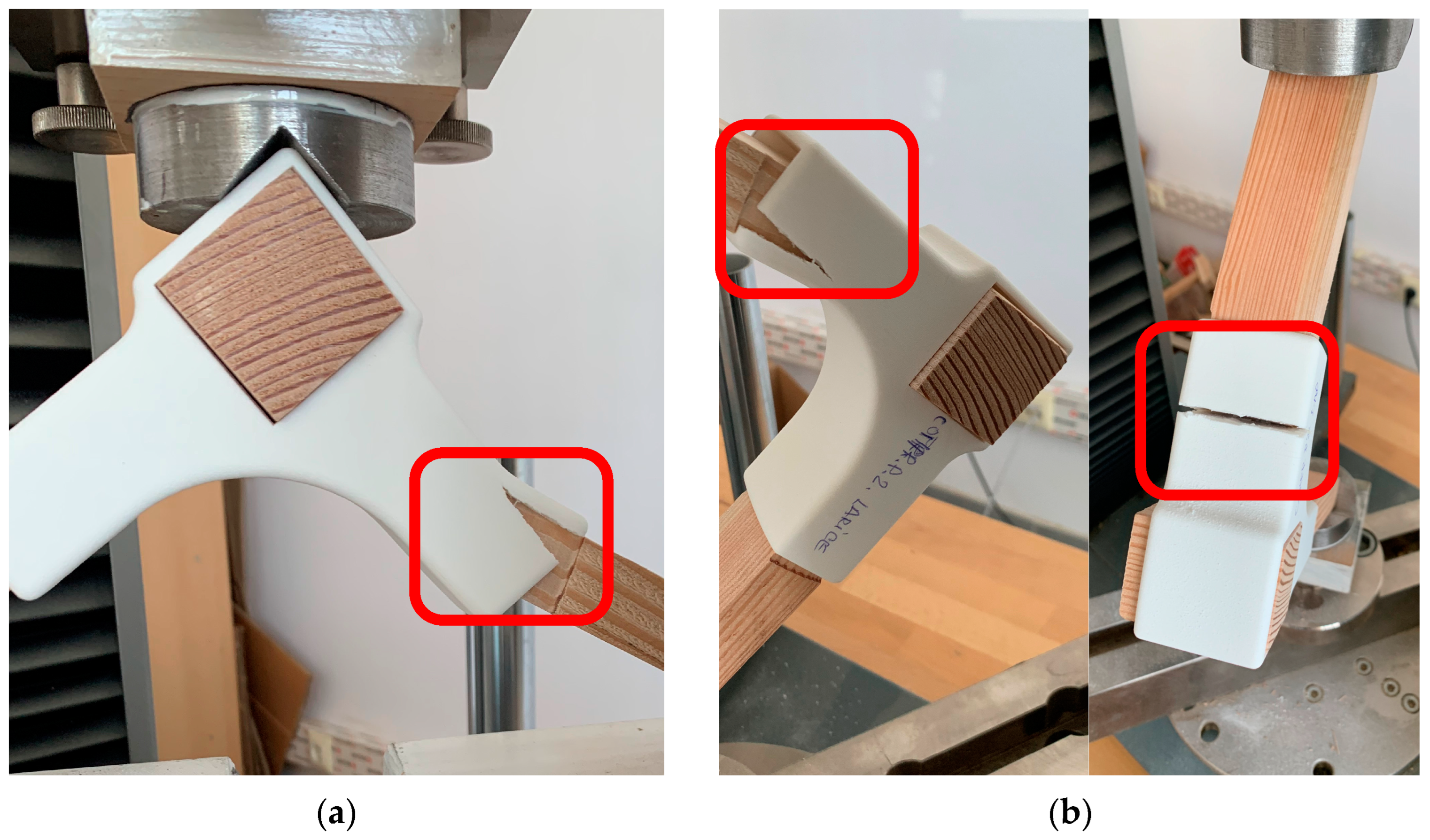
3.2. Micrography of the Connectors after Mechanical Testing

The image in Figure 10a shows the detachment of the powder granules due to the tensile loads applied to the chair elements assembled with a 3D-printed connector. The crack was placed longitudinally on the corner of the connector. As can be seen in this image, there is a random distribution of the detached powder granules, indicating bonding damage of the different deposited powder layers using the SLS technology. The particle fusion can be explained by several factors that can affect the uniform deposition of the new powder layer on the previous one, such as the energy density and scan speed. Low energy density creates a porous structure and layer delamination with a negative impact on the mechanical properties of the printed object [8]. Contrarily, the high laser power and the fast scan speed can produce the balling defect [6,9], which often leads to cracks.
The image in Figure 10b shows the linear detachment of the powder granules in the case of breaking the connector in the transversal direction (as seen in Figure 9b right), as a result of compression loading. This can be explained by the low bonding between two adjacent sintered layers of powder. In the marked area in Figure 10b, the balling defect is highlighted, which could cause the breaking of the part. According to the observations of researchers [9,26], the orientation of the part during the SLS printing process has an influence on the nature of the fracture. Thus, on the 0° orientated parts, a serrated fracture occurs after mechanical testing, because the force is applied along the layers, and the weak areas are fractured, a phenomenon which explains the fracture presented in Figure 10a. In the case of the 90° orientation of the part, the force is applied perpendicular to the layers, causing a straight fracture between two subsequent layers, a fact that may explain the occurrence of the fracture presented in Figure 10b.
As noticed by other researchers [24,26] who studied the behavior of 3D-printed dowels made from PA12 by applying SLS technology and which were used for L-type corner joints designed for case-type furniture, during the diagonal tensile and compression tests, the normal and shear stresses occurring in the cross-section of the dowels exceeded the stress limits of the PA12 material. As a result, the failures of the dowels occurred on their entire cross-section, as for the connector presented in Figure 9b.
Reducing the unnecessary excessive strength of the classical wooden joints by replacing them with joints with 3D-printed connectors can bring important advantages: no limitation in design and build complex structures, rapid execution, saving money, time and materials [18].

4. Conclusions

The present paper investigated the possibility of replacing the classical mortise–tenon joint between the leg and two stretchers of a chair with a 3D-printed connector using SLS technology. The L-type corner joint models built with the two variants were subjected to diagonal compression and diagonal tensile testing, and the results of the bending moment capacities calculated based on the maximum breaking load were compared. The 3D-printed connector did not enrich the mechanical performance of the glued mortise–tenon joint used to assemble the chair leg with the stretchers made from larch wood. Whilst the maximum failure load damaged the joint and produced deep cracks in the leg element of the wooden L-corner type mortise–tenon joint, in the case of using the 3D-printed connector, cracks occurred at the corners where the stretcher edges pressed the connector, favoring the stretcher to come out from the assembly, but the wood elements were not affected. This may be an advantage of using the connectors instead of wooden joints, because they can be replaced and the chair becomes functional again. The microscopy of the printed parts shows the defects in the structure of the connector, which can be eliminated in further research by modifying the printing parameters such as the laser power and the scan speed. The change in the method of 3D printing and also the use of other materials are the next steps of the research in this field. Extending the testing methods to the final product is also a challenge. On the other hand, the change in the shape of the connector for the round section of the stretcher is another subject of further research.

Author Contributions

Conceptualization, A.N. and C.C.; methodology, M.A.P.; software, M.A.P.; validation, C.C., M.A.P. and A.N.; formal analysis, C.C.; investigation, S.V.G.; resources, A.N., C.C., M.A.P. and S.V.G.; data curation, A.N., C.C. and M.A.P.; writing—original draft preparation, C.C.; writing—review and editing, C.C. and M.A.P.; visualization, A.N. and S.V.G.; supervision, C.C.; project administration, A.N.; funding acquisition, A.N. All authors have read and agreed to the published version of the manuscript.

Funding

We hereby acknowledge the structural funds project PRO-DD (POS-CCE, O.2.2.1., ID 123, SMIS 2637, No. 11/2009) for providing the infrastructure used in this work and the Contract No. 7/9.01.2014.

Institutional Review Board Statement

Not applicable.

Informed Consent Statement

Not applicable.

Data Availability Statement

Data are contained within the article.

Conflicts of Interest

The authors declare no conflict of interest.

References

  1. Ayidin, M. Additive Manufacturing: Is It a New Era for Furniture Production? J. Mech. Eng. Autom. 2015, 5, 338–347. [Google Scholar]
  2. Reddy, K.S.; Dufera, S. Additive Manufacturing Technologies. Int. J. Manag. Inf. Technol. Eng. 2016, 4, 89–112. [Google Scholar]
  3. Wong, K.V.; Hernandez, A. A Review of Additive Manufacturing. Int. Sch. Res. Not. 2012, 2012, 208760. [Google Scholar] [CrossRef]
  4. Ramya, A.; Vanapalli, S. 3D Printing Technologies in Various Applications. IJMET 2016, 7, 396–409. [Google Scholar]
  5. Przestacki, D.; Sieniawski, J.; Stambolov, G.; Lisiak, P. An Overview of Selective Laser Sintering Technologies. Arch. Mech. Technol. Mater. 2015, 16, 23–32. [Google Scholar]
  6. Tolochko, N.K.; Mozzharov, S.E.; Yadroitsev, I.A.; Laoui, T.; Froyen, L.; Titov, V.I.; Ignatiev, M.B. Balling processes during selective laser treatment of powders. Rapid Prototyp. J. 2004, 10, 78–87. [Google Scholar] [CrossRef]
  7. Simchi, A.; Pohl, H. Effects of laser sintering processing parameters on the microstructure and densification of iron powder. Mater. Eng. 2003, A359, 119–128. [Google Scholar] [CrossRef]
  8. Korycki, A. Study of the Selective Laser Sintering Process: Materials Properties and EFFECT of Process Parameters. Ph.D. Thesis, Institut National Polytechnique de Toulouse (Toulouse INP), Labège, France, 2020. Available online: https://oatao.univ-toulouse.fr/27651/1/Korycki_Adrian.pdf (accessed on 15 September 2023).
  9. Han, W.; Kong, L.; Xu, M. Advances in selective laser sintering of polymers. Int. J. Extrem. Manuf. 2022, 4, 042002. [Google Scholar]
  10. Felek, S.Ö. A new Era in Furniture Production: 3D Printer. International Conference on Knowledge & Innovation in Engineering, Science &Technology, March 2020, Budapest, Hungary. Available online: www.kiconf.org (accessed on 15 September 2023).
  11. Smardzewski, J.; Rzepa, B.; Kılıç, H. Mechanical Properties of Externally Invisible Furniture Joints Made of Wood-Based Composites. Bioresources 2016, 11, 1224–1239. [Google Scholar] [CrossRef]
  12. Nicolau, A.; Pop, M.A.; Coșereanu, C. 3D Printing Application in Wood Furniture Components Assembling. Materials 2022, 15, 2907. [Google Scholar] [CrossRef]
  13. Kasal, A.; Kuşkun, T.; Smardzewski, J. Experimental and Numerical Study on Withdrawal Strength of Different Types of Auxetic Dowels for Furniture Joints. Materials 2020, 13, 4252. [Google Scholar] [CrossRef] [PubMed]
  14. van Wassenhove, R.; De Laet, L.; Vassilopoulos, A.P. A 3D printed bio-composite removable connection system for bamboo spatial structures. Compos. Struct. 2021, 269, 114047. [Google Scholar] [CrossRef]
  15. Swetham, T.; Reddy, K.M.M.; Huggi, A.; Kumar, M.N. A Critical Review on of 3D Printing Materials and Details of Materials used in FDM. Int. J. Sci. Res. Sci. Eng. Technol. 2017, 3, 353–361. [Google Scholar]
  16. Li, X.; Ni, Z.; Bai, S.; Lou, B. Preparation and Mechanical Properties of Fiber Reinforced PLA for 3D Printing Materials. IOP Conf. Ser. Mater. Sci. Eng. 2018, 322, 022012. [Google Scholar] [CrossRef]
  17. Liang, L.; Huang, T.; Yu, S.; Cao, W.; Xu, T. Study on 3D printed graphene/carbon fiber multi-scale reinforced PLA composites. Mater. Lett. 2021, 300, 130173. [Google Scholar] [CrossRef]
  18. Valiyousefi, M.; Alihedarloo, A. A Study the impact of 3D-printed joints on the complex wooden structures. In Proceedings of the International Congress on Science & Engineering University of Tokio, Tokyo, Japan, 14–15 October 2019. [Google Scholar]
  19. Ngo, T.D.; Kashani, A.; Imbalzano, G.; Nguyen, K.T.Q.; Hui, D. Additive manufacturing (3D printing). A review of materials, methods, application and challenges. Compos. Part B 2018, 143, 172–196. [Google Scholar]
  20. Martínez, J.; Dumas, J.; Lefebvre, S. Procedural Voronoi Foams for Additive Manufacturing. ACM Trans. Graph. 2016, 35, 1–12. [Google Scholar] [CrossRef]
  21. Martínez, J.; Hornus, S.; Song, H.; Lefebvre, S. Polyhedral Voronoi diagrams for additive manufacturing. ACM Trans. Graph. 2018, 37, 1–15. [Google Scholar] [CrossRef]
  22. Capone, M.; Lanzara, E.; Portioli, F.P.A.; Flore, F. Digital Form Finding Using Voronoi Pattern. Nexus Netw. J. 2021, 23, 959–975. [Google Scholar] [CrossRef]
  23. Ayrilmis, N.; As, N.; Dündar, T.; Şendağ, A. Determination of Bending Moment of L-Type Corner Joints Used in Chair Production and Their Effects on Mechanical Performance of Chairs. Mater. Int. 2020, 2, 0318–0323. [Google Scholar]
  24. Kasal, A.; Smardzewski, J.; Kuşkun, T.; Güray, E. Analyses of L-Type Corner Joints Connected with Auxetic Dowels for Case Furniture. Materials 2023, 16, 4547. [Google Scholar] [CrossRef] [PubMed]
  25. Yerlikaya, N.C. Failure load of corner joints, which are reinforced with glass-fiber fabric in case-type furniture. Sci. Res. Essays 2013, 8, 325–339. [Google Scholar]
  26. Krzyźaniak, Ł.; Smardzewski, J. Impact damage response of L-type corner joints connected with new innovative furniture fasteners in wood-based composites panels. Compos. Struct. 2021, 255, 113008. [Google Scholar] [CrossRef]
  27. Ke, Q.; Lin, L.; Chen, S.; Zhang, F.; Zhang, Y. Optimization of l-shaped corner dowel joint in pine using finite element analysis with Taguchi method. Wood Res. 2016, 61, 243–254. [Google Scholar]
  28. Hajdarevic, S.; Kuzman, M.K.; Obucina, M.; Vratuša, S.; Kušar, T.; Kariž, M. Strength and stiffness of 3D-printed connectors compared with the wooden mortise and tenon joints for chairs. Wood Mater. Sci. Eng. 2023, 18, 870–883. [Google Scholar] [CrossRef]
  29. Dupin, S.; Lame, O.; Barrès, C.; Charmeau, J.-Y. Microstructural origin of physical and mechanical properties of polyamide 12 processed by laser sintering. Eur. Polym. J. 2012, 48, 1611–1621. [Google Scholar] [CrossRef]
  30. Schmid, M.; Wegener, K. Additive manufacturing: Polymers applicable for laser sintering (LS). Proc. Eng. 2016, 149, 457–464. [Google Scholar] [CrossRef]
  31. Beal, V.; Paggi, R.A.; Salmoria, G.; Lago, A. Statistical Evaluation of Laser Energy Density Effect on Mechanical Properties of Polyamide Parts Manufactured by Selective Laser Sintering. J. Appl. Polym. Sci. 2009, 113, 2910–2919. [Google Scholar] [CrossRef]
Figure 1. Dimensions of samples prepared for the experimental research: (a) Reference sample with stretchers and legs mortise–tenon jointed; (b) Assembled leg and stretchers with the 3D-printed connector (up) and connector’s dimensions (the yellow arrows represent the limit of introducing the wooden part into the connector).
Applsci 13 12044 g001
Figure 2. Position of printing the connector (yellow circled one).
Applsci 13 12044 g002
Figure 3. Sizes of the particles of new PA12 powder.
Applsci 13 12044 g003
Figure 4. Schematic representation of the laser beam radiation.
Applsci 13 12044 g004
Figure 5. Loading of the L-type corner joint specimens: (a) under tensile testing, (b) under compression.
Applsci 13 12044 g005
Figure 6. L-type corner joint test specimens: (a) diagonal tensile testing for mortise–tenon jointed parts (top) and specimen with a 3D-printed connector (bottom); (b) diagonal compression testing for mortise–tenon jointed parts (left) and specimen with a 3D-printed connector (right).
Applsci 13 12044 g006
Figure 7. Tensile and compression bending moments of the joints.
Applsci 13 12044 g007
Figure 8. Typical defects occurred in the reference sample after mechanical testing: (a) at tensile; (b) at compression.
Applsci 13 12044 g008
Figure 9. Typical defects occurred in the 3D-printed connector after mechanical testing: (a) at tensile; (b) at compression. The red frames highlight the cracks occurring in the 3D-printed connector.
Applsci 13 12044 g009
Figure 10. Defects of the connector after mechanical testing: (a) A crack occurred after tensile testing on the longitudinal direction at the corner of the part; (b) A rupture of the connector on the transversal direction, after the compression testing. The red frame indicates the area where printing defects were noticed.
Applsci 13 12044 g010
Table 1. Characteristics of DuraForm PA Plastic.
PropertyValue
Specific Gravity, g/cm31.00
Moisture Absorption—24 h0.07%
Tensile Strength Ultimate, MPa43
Tensile Modulus, MPa1586
Elongation at break, %14
Charpy Impact Unnoched, J/m2336
Charpy Impact Noched, J/m232
Flexural Strength, Ultimate MPa48
Flexural Modulus, MPa1387
Shore Hardness73
Disclaimer/Publisher’s Note: The statements, opinions and data contained in all publications are solely those of the individual author(s) and contributor(s) and not of MDPI and/or the editor(s). MDPI and/or the editor(s) disclaim responsibility for any injury to people or property resulting from any ideas, methods, instructions or products referred to in the content.

