Abstract
Beam–column connection zones are high regions of interest in reinforced concrete (RC) structures, which are expected to respond elastically to seismic loads. Using carbon fiber-reinforced polymers (CFRP) to improve these connections, performance is critical in retrofitting deficient RC frames because existing slabs may pose numerous limitations in the design and wrapping of CFRP sheets in joints. The main aim of this research is to develop a new design for flange-bonded CFRP retrofit of frames, including slabs, for the relocation of plastic hinges of the connection area toward the beam and to develop beam–column joint capacity and building stability in cases of subjection to dynamic loads. The performance of these proposed retrofittings was explored both experimentally and numerically. Two full-scale fabricated interior RC joints of a real moment-resisting frame with moderate ductility were subjected to monotonic loads before and after retrofitting, and the results were used to detail the numerical progress and verify of the beam–column connection. Moreover, a parametric study was conducted on CFRP sheets’ optimal thickness to examine its influence on plastic hinge relocation in the connection region. Results show that the retrofitting method can efficiently relocate the plastic hinge to the mid-span of the beam, which, in turn, leads to improved capacity and achievement of the RC frame and guarantees better structural safety a lower cost.
1. Introduction
The use of carbon fiber-reinforced polymers (CFRPs) is to repair and retrofit reinforced concrete members, and this has lately given rise to an extreme eagerness and interest expressed by researchers and engineers alike [1,2,3]. The rehabilitation of such frames can be carried out locally by strengthening individual elements such as beams, columns, and beam–column connections, or globally by including shear-resisting elements such as shear walls or braces. Various strengthening methods for RC frames, which were not designed for seismic loads, were proposed by employing carbon fiber-reinforced polymer (CFRP) to enhance the collapse-resistant capacity of the joints. The experimental test results showed that the proposed reinforcement designs could effectively increase the load resistance capacity of the joint but failed to reduce the severe softening behavior [4]. The response of non-ductile, heat-damaged reinforced concrete (RC) beam–column joints was investigated through some experimental research works. The findings proved a considerable improvement in the cyclic performance of the joints strengthened with a hybrid CFRP system [5]. In an experimental study, the behavior of three-dimensional reinforced concrete joints under combined lateral and gravity loads was tested via the strength method with CFRP composite sheets on two reinforced samples, which showed an increase in strength of 9% to 23% [6]. Many studies were carried out on the strengthening of 3D external RC beam–column joints without transverse bars in their common core using CFRP. The results indicated that strengthening prevents the diagonal shear failure at the column in the transverse beam connection point, and also increases the lateral load capacity by 11–15%, energy absorption by 10–20%, and energy loss by 2.2 times [7]. Thereafter, the seismic response of a beam–column connection with a shear deficiency (BCJ) reinforced with UHPFRC and/or CFRP was investigated. The results revealed that the synergistic action of UHPFRC and CFRP can increase the structural stiffness, strength, and energy dissipation capacity of the BCJ compared to other strengthening techniques [8]. In general, beam–column connections are a vital component of the structure not only in terms of stability but also in terms of seismic performance. By strengthening a basic building model, one can witness the bending effects of improving accuracy and reducing computational effort, and this method is effective for the earthquake-resistant design of frames [9]. In particular, shifting the formation location of plastic hinges off the column toward the beam interval is a useful method geared toward increasing the beam–column connection capacity, which can further enhance the overall seismic structural performance. To effectively relocate a plastic hinge, different retrofitting plans can be positioned, for example, web- and flange-bonded approaches and simultaneous web–flange-bonded approaches [10,11]. Literature-wise, much of the bulk of research in this area in recent years has focused on the former.
The experimental assessment of RC beam–column connections, either internally with steel bars or externally via CFRP sheets, has proven its capacity for noticeable joint enhancement through this strengthening technique [12]. In particular, the work has emphasized joint behavior under reverse cyclic loading to assess deformation capacity and strength. As a result, the findings have indicated that the bearing capacity and ductility of the connections are closely related to the original element condition and strengthening application. Furthermore, several rehabilitation schemes concerning joints with CFRP composites have been evaluated, whereby their configurations in the forms of U and X can be exemplified accordingly [13]. Therefore, it is reported that all schemes selected can successfully modify the mode from joint non-ductile shear failure to ductile-flexural. The results of experimental and numerical studies revealed that when the joints in an RC frame are reinforced by CFRP, at that moment, the capacity increases by 37%, whereas a maximum of 18% decrement of joint rotation is observed [14,15].
The results of the test for the RC joints retrofitted by hybrid CFRP sheets consequently suggest that this scheme may efficiently ameliorate the stiffness and rehabilitate the joint capacity efficiently [16]. The effectiveness of near-surface-mounted carbon-reinforced polymer ropes for enhancing interior-reinforced concrete (RC) beam–column joints was investigated. The X-shaped rope, implemented with two ropes on each side of the beam and two on each side of the column, imparted the best effectiveness on stiffness and yielding load, and the stiffness increased by 236.7% compared to the control beam–column joint [17]. Thereafter, a full-scale 3D exterior beam–column joint, lacking shear reinforcement but externally shear-strengthened with CFRP sheets, was investigated with respect to its behavior under both gravity and lateral cyclic loadings. The results revealed enhancements in lateral load-bearing capacity, energy dissipation, and secant stiffness [18]. Meanwhile, the effects of externally strengthened connections by utilizing several kinds of composites have been experimentally studied, and the results revealed that the simultaneous use of CFRP and glass fiber-reinforced polymer (GFRP) is capable of resolving the issues of lacking ductility and shear strength of problematic joints [19]. The effect of a set of parameters related to the contribution of CFRP sheets that were externally attached to the joint was numerically investigated. The obtained results confirmed the effectiveness of the CFRP-strengthening technique with respect to a relatively wide range of considered parameters [20]. An investigation detailing RC beam–column joints strengthened with steel-reinforced polymer (SRP) systems and their seismic performance has been presented by Alessandro De Vita, and the results of an experimental campaign performed at the Laboratory of Materials and Structural Testing of the University of Salerno, Italy, have been published [21]. In the research, the outcomes of cyclic tests performed on SRP-strengthened joints have been examined via a comparison against those obtained from a prior experimental program. They include companion specimens otherwise not provided with transverse beam stubs and strengthened by CFRP systems.
Parallel to the above work, another scholarly attempt by Antonopoulos and Triantafillou has tested some scaled joints modified by using CFRP [22]. In particular, either partial or full debonding of composites has been identified as the dominating factor across the test results. Nonetheless, the work has shown that a 20% increment in strength and energy dissipation and a 100% increase in stiffness are both possible. Additionally, the analytical prediction of shear strength carried out was in decent agreement with the experimental results. Thereafter, to evaluate the joint performance, CFRP-retrofit methods were applied to fortify RC joints and results revealed that the use of appropriately increasing composites can considerably enhance the ductility and strength of joint samples laterally [23]. Moreover, another numerical study concluded that the extent of the effectiveness of the CFRP web-bonding of joints toward the relocation of a hinge is used in order to yield a seismically enhanced performance of an RC structure [24]. Here, comparisons have been made accordingly between the results of frame retrofitting at the joints’ webs using CFRP sheets and steel braces [25]. The numerical model for RC joints with CFRP-cover has been developed and nonlinear analyses have been conducted. As a result, the numerical model proposed in the work is capable of predicting the experimental work with precision [26].
The investigation on the method of web-bonded strengthening in the case of deficient RC joints with CFRP confirmed its ability to restore and further upgrade the strength of the system [27]. Moreover, the proposed scheme has been demonstrated as possibly preventing brittle failure from occurring in the core of a joint, which is attributable to the formation of plastic deformations in the form of hinges relocated off the column. Moreover, the study has revealed that the schemes are capable of improving the behavior factor of the frame in the CFRP, as well as influencing the ductility while the bracing approach influenced the strength. As a further matter, the authors have highlighted the limitations of the web-bonded approach in the context of plastic hinge relocation in large joints, suggesting that the combined web–flange-bonding method could be more effective. A diamond wire saw-cutting technology was adopted to achieve annular wrapping of the joint core area with the CFRP sheets. It was indicated that the proposed method improved the shear bearing capacity of the joint core area, inhibited the development of diagonal cracks in the joint core area, and transferred the failure location mode [28]. Furthermore, similar studies have yielded the same results with regard to the joint web-bonded scheme in which the practical limitations of web-bonded and web–flange-bonded schemes are both considered for retrofitting real 3D RC joints [29,30].
Through the same application, another study utilized cementitious mortar to enhance the bond between CFRP rod panels [31], whereas the use of embedded CFRP rods in the beam–column joints in areas of high humidity has also been proposed [32]. The latter study opted for this method to prevent steel bar corrosion from occurring, therefore conducting the experimental study on a prototype under applied cyclic loads. In another numerical investigation, the efficiency of RC joints retrofitted with CFRP laminates has been investigated in detail [33]. For this purpose, three practical CFRP configurations were proposed, and the joint behavior was assessed via a detailed numerical model in FE software (i.e., ANSYS, 2019 R1) by subjecting them to monotonic non-linear analyses. The results revealed that the grooving method can shift the plastic hinge location off the column vicinity. Similarly, another numerical investigation aimed at studying the effects of the flange-bonded approach, which is geared at having the location of plastic hinges changed off the column face [34]. Scholars have conclusively stated that the flange-bonded approach leads to better results compared to the use of the web-bonded method, whereby their differences encompass several aspects including ductility, cost, capacity, and performance level. Moreover, they have given a report of the excellent compliance shown by the CFRP flange-bonded scheme performance compared with that of the steel-bracing method [35,36].
More recently, another study has presented a complete summary of the results obtained following the analytical and numerical simulations of the structural behavior possessed by RC beam–column joints retrofitted with different types of fiber-reinforced polymeric (CFRP) composite laminates and hybrid connectors. In the process, non-linear numerical simulations were performed to evaluate the behavior of the beam–column joints, of which the behavior of eight full-scale interior RC beam–column specimens was numerically evaluated [37]. As the beam–column joint is considered as the initial point to introduce plastic hinges when the frame is subjected to lateral load [38], many efforts have been made to relocate the plastic hinge formation from the joint to the beam section. This is achieved by using CFRP strengthening to sustain the structure stability [39]. In line with this, many numerical and analytical studies have been conducted to predict concrete section deformation retrofitted using CFRP plates and rods [40], while increasing the bonding between CFRP and concrete.
Based on the extensive literature review in this research, beam–column joints have been identified as the main causes of vulnerability in the RC frame in forming plastic hinges during structure loading, which may lead to its collapse. However, most of the research in the literature has focused on increasing the strength of beams or columns in the joint area; the location of the plastic hinge in the retrofitted joint has not been considered, even though the occurrence of a plastic hinge in the beam–column connection is the most critical threat to the functioning of the joint when the structure is subjected to catastrophic excitations. Hence, implementing an appropriate retrofitting method is required to prevent plastic hinge formation in the beam–column joint area. Therefore, the main aim of this research is proposing a new retrofitting scheme for beam–column connections in the RC frame using CFRP to relocate and shift plastic hinge from near the face of the column to the further length of the beam. Then, the joint is protected against applied excitations and able to function properly to provide structural safety and integrity.
For this purpose, in the present study, the newly proposed retrofitting scheme has been applied to the RC joint (beam–column connection), and experimental and numerical investigations have been carried out. Accordingly, two full-scale RC interior joints from a moment-resisting frame with moderate ductility have been cast and experimentally tested, and the results were used to validate the numerical solutions and to evaluate the performance of the CFRP flange-bonded retrofitting scheme. Furthermore, a parametric study has been conducted to find the optimal thicknesses of the CFRP sheets for relocating the plastic hinges from near the face of the column to further along length of the beam.
2. Seismic Retrofitting of Reinforced RC Structures Using CFRP Sheets
Recent earthquakes have underscored the vulnerability of existing structures to seismic loads, emphasizing the urgent need to address the structural integrity and seismic resilience in older buildings. These events have highlighted the shortcomings of many existing structures, particularly those built before modern seismic codes and standards were established. Consequently, there has been a growing focus on seismic retrofitting methods to enhance the resistance and performance of reinforced concrete structures against severe ground motion.
One widely employed method in seismic retrofitting is the use of carbon fiber-reinforced polymer (CFRP) sheets to strengthen beams and columns. Civil engineers frequently turn to this technique due to its effectiveness in enhancing the seismic performance of structures. However, the critical challenge lies in the proper design of the retrofitting scheme. Achieving the desired level of performance while maintaining the structural integrity and stability of the existing building is of paramount importance. A well-executed retrofitting plan not only bolsters the structure’s ability to withstand seismic forces but also ensures that the retrofit elements integrate seamlessly with the original construction, minimizing the risk of unforeseen issues. In the ongoing effort to mitigate earthquake-related risks, special attention to retrofit design and execution remains a vital aspect of safeguarding vulnerable structures and, ultimately, the safety of the people who inhabit them. The interest in the use of CFRP materials in the retrofitting of defective RC frame beam and column connections is growing remarkably, as the methods have advantages, for example:
(i) Improved seismic performance: Beam–column connections are critical areas in a structure, and defects in these areas can severely deteriorate seismic performance of buildings. CFRP materials can be effectively used to strengthen these connections to increase the ductility, which led to better the withstanding of earthquake forces. This increase in ductility helps to prevent easy failures and ensures the structure’s resilience in the event of an earthquake by reducing catastrophic damage.
(ii) Lightweight and corrosion resistant: CFRP composites are lightweight as compared to the conventional steel jacketing method. This advantage makes them particularly suitable for retrofitting and strengthening work as they add less weight to the existing structure. Furthermore, CFRP materials do not corrode, which is a significant advantage over steel reinforcement. Steel corrosion can weaken connections over time, while CFRP retains its strength and integrity, providing long-term durability and reliability.
(iii) Ease of installation: CFRP materials are relatively easy to install and can be used for retrofitting a structure to address specific defects in beam–column connections. This ease of installation can reduce maintenance work during the renovation.
(iv) Tailored retrofitting solution: CFRP retrofitting can be conducted according to the specific configuration of structural elements. Engineers can target specific defects and weaknesses in a given RC frame by designing a CFRP reinforcement system. This tailored approach ensures repeatability.
Therefore, these advantages make CFRP a valuable and versatile tool in enhancing the safety and longevity of existing structures, particularly in earthquake-prone regions. In this study also, CFRP sheets have been selected for retrofitting the joints among all other fibers. CFRP is preferred because it possesses higher tensile strength and stiffness compared to other types of fibers thanks to the exceptional strength of carbon fibers. Additionally, it is lighter, more corrosion-resistant, and better equipped to withstand high temperatures when compared to other fiber types. Therefore, CFRP materials are better suited for retrofitting RC joints, given their critical function.
Although using carbon fiber-reinforced polymer (CFRP) sheets in retrofitting existing RC frames with slabs presents specific challenges that impact the performance of the retrofitted structure. The primary challenge when using CFRP is achieving a strong and durable bond between the CFRP sheets and the existing concrete surface to transfer the load. Proper surface preparation of the concrete is highly effective in ensuring a strong bond between CFRP and the existing concrete. Inappropriate adhesive selection and inadequate surface finishing can lead to delamination of CFRP sheets during seismic events, compromising the effectiveness of the retrofitting.
Furthermore, the type of adhesive and its thickness are highly effective in bonding CFRP to the concrete and consequently in the strength of the RC beam–column joint. Implementing the appropriate adhesive is able to influence the durability of the bonding and the load-bearing capacity significantly. Special types of adhesives are formulated to provide high-strength bonding; other types provide flexible bonding but are more resistant against environmental threats. Similarly, adhesive thickness is highly impactful on the quality of bonding and the strength and performance of the retrofitted RC joint using CFRP.
An insufficient adhesive layer may lead to a reduction in the integrity of CFRP sheets with the concrete surface, while excess thickness can create voids or uneven stress distribution, potentially compromising the structural integrity. Therefore, implementing the appropriate adhesive type and suitable thickness can be highly contributed to achieving a reliable binding between CFRP sheets and concrete to perform together to enhance the strength and functionality of the retrofitted RC joint.
This bonding is especially critical for RC frames with slabs due to the limited accessibility for creating a full loop of CFRP layers around the beams. Proper anchorage and confinement can be achieved by applying CFRP sheets to the surrounding structural elements, which is not feasible for beams in frames with slabs due to their geometry.
The beam–column joint plays a crucial role in the integrity of reinforced concrete structures when subjected to lateral loads, such as earthquakes. Due to the rigidity of these connections in RC structures, the first plastic hinges often appear in the vicinity of these joints as the lateral load is transferred from the beams to the columns. This can result in a reduction in the strength of the beam–column joint, leading to instability and compromising the overall structural integrity. Therefore, the aim of this research is to propose a retrofitting scheme using CFRP sheets to relocate the occurrence of plastic hinges in the RC beam–column connections from near the column face to further within the beam. This approach is designed to enhance the safety of the joint, providing stability and preserving the structural integrity when exposed to severe earthquake excitations.
3. Experimental Setup
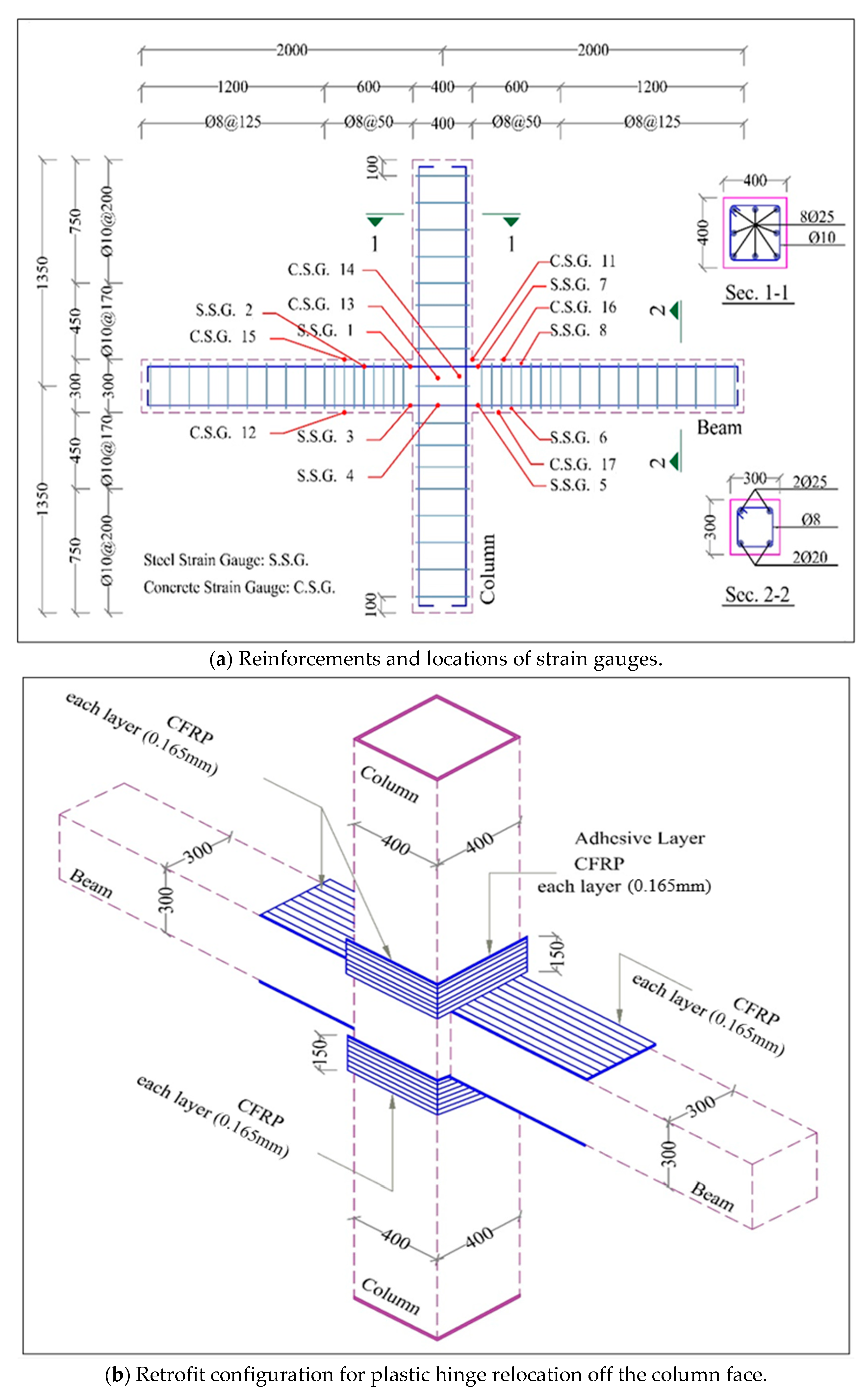
The experimental setup consisted of two full-scale RC interior joints of a moment-resisting frame with moderate ductility (Figure 1) prepared according to ACI codes (440.2R-17) [41]. A plain specimen (CS1) was ordered as the control specimen, and another section that was later retrofitted with a flange-bonded scheme (RS1) was constructed and tested under monotonic loading until sample failure. The joints were chosen from a typical four-story RC structure and consisted of half-length lower and upper floor columns that were 2700 mm (2.7 m) in height with half-length left and right beams with a length of 4000 mm (4 m) and dimensions of column joint cross-sections of 400 × 400 mm2. Additionally, 8Φ25 bars were used to longitudinally reinforce the columns, complying with a 2.4% reinforcement ratio. Rectangular Φ10 ties were used as transverse reinforcements. Each two-column ties were 170 mm apart inside the joint, 600 mm above and below the joint, and 200 mm in the general length of the column. All beams had a length of 1800 mm (1.8 m) from the column to the free end, and the cross-section selected was 300 × 300 mm2. Two bars (i.e., Φ25) were employed for reinforcement of the beams at the top and two bars (i.e., Φ20) at the bottom. Φ8 rectangular stirrups were used as transverse reinforcements of the beams (Figure 1). The stirrups were 50 mm from one another in the first 600 mm. The yield strengths of the reinforcing steel were 400 MPa for the bars and ties. However, the concrete compressive strength reached 21.5 MPa for the standard cylinder samples. The ultimate stress and strain and elasticity modulus of the unit-directional CFRP used in the models were, respectively, f_FRP = 3900 MPa, 0.0155 mm/mm, and 240 GPA. In the retrofitted specimen with the flange-bonded scheme (RS1), FRP laminates covered the top and bottom flanges of the ends of the beams, which joined the connection, extending so as to cover the adjoining column faces. The joint was covered by 5 FRP layers. The total thickness for 5 layers of FRP is 0.825 mm. The length of CFRP sheets was kept constant at 300 mm for the joint based on recommendations by Pauley and Priestly [31] for desirable plastic hinge relocation. In the design of this experiment, an attempt has been made to investigate the relocation of plastic hinges when the load is applied to the end of beams. Therefore, to maintain the same strength for the beam against both in-plane and out-of-plane loads, the square section has been employed to extend the results of this study for the frame exposed to lateral loads in future studies.
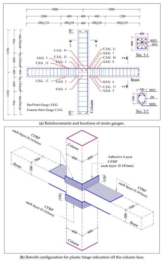
Figure 1.
Details of sections and retrofitting configuration.
3.1. Test Setup and Loading Sequence
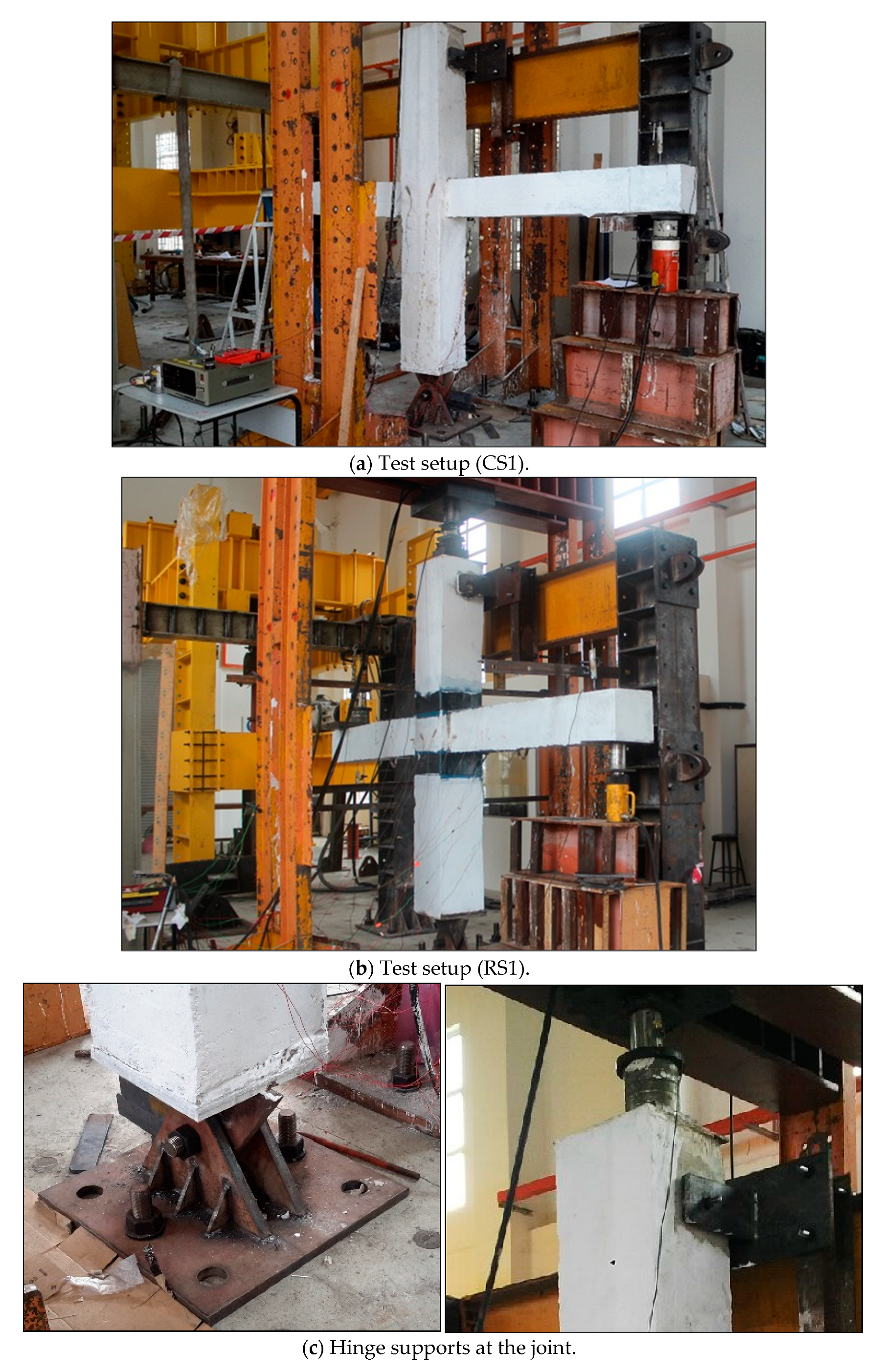
The laboratory experiment details are shown in Figure 2. The samples were placed under a constant axial load on the column and two monotonic loads on the beam end. The applied load was measured by a load cell. As to simulation of the inflection points at the upper and lower centers of the columns, each end of the column is specially designed to support it, ensuring free end rotation. For this purpose, a pinned support was placed at the column base, and a roller support was exerted on the top. A vertical slot with a length of 2 cm was provided for the roller to allow vertical deformations in the column to suitably transmit the axial load in the column to the hinge support (Figure 2c). The test was conducted step-by-step, and monotonic “pushover” loads were applied until destruction. In the design of the experimental test, to provide a realistic RC joint condition, an attempt was made to apply the axial load equivalent to 10% of the column strength, which is 150 kN, to subject the column to a compressive condition. The column load, equaling 150 kN, was kept constant, whereas the loads on the beam’s tips were simultaneously and gradually increased, starting from zero, while corresponding displacements and strains were recorded.
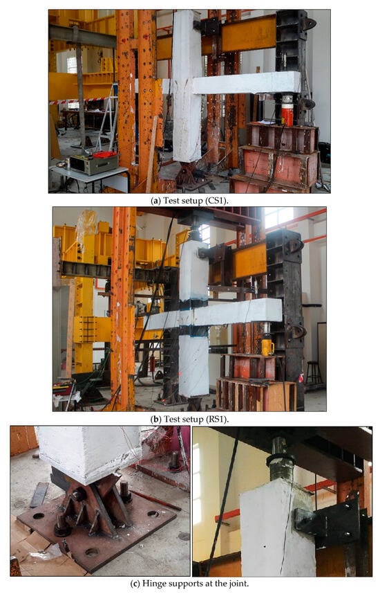
Figure 2.
Details of test setup.
3.2. Instrumentation and Data Acquisition
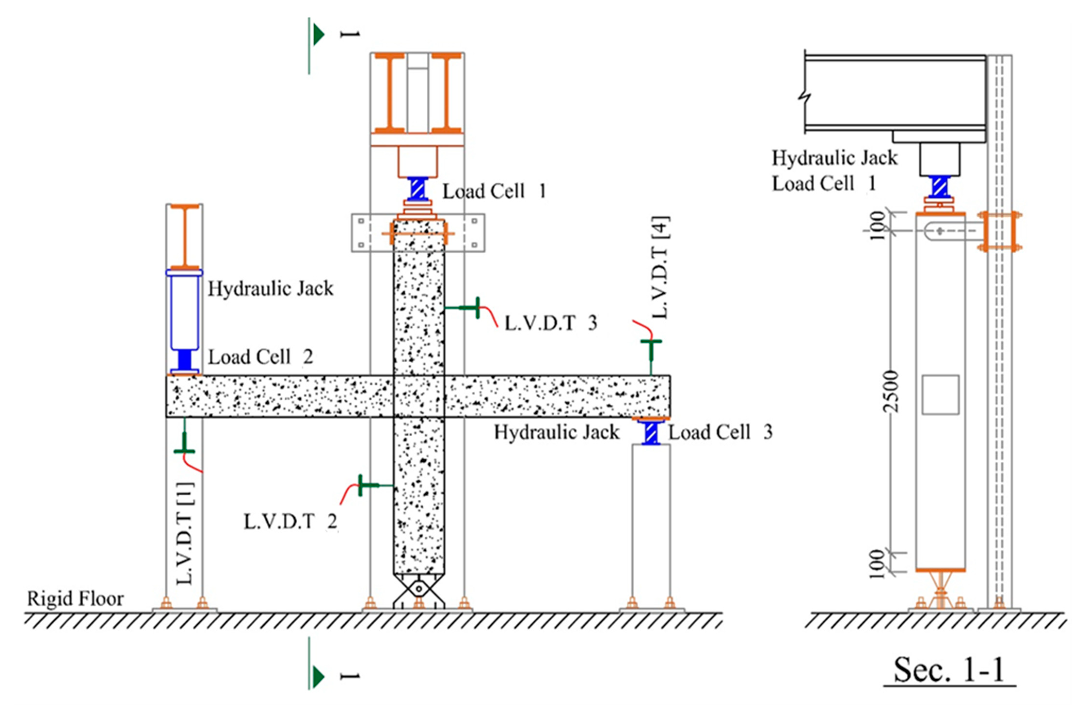
The devices utilized for the test included displacement transducers, load cells, and strain gauges, and all data were transferred simultaneously to the data logger. The column axial load and the loads applied to the beams’ tips were controlled by load cells. For this purpose, in the experimental test setup, three Kyowa load cells (force transducers) with a capacity of 300 kN and 150 kN have been employed to measure the applied force on the column and at the ends of two beams. The positions of these load cells are depicted in Figure 3.
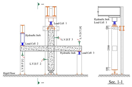
Figure 3.
Schematic view of the LVDT sensor positions in experimental test.
Additionally, four units of KYOWA LVDT sensors (displacement transducers) capable of measuring deformations up to 100 mm in the test setup have been utilized. Two of the LVDTs were installed at the midpoints of the columns, both at the top and bottom, to measure the deformation of the column under applied axial pressure at the top. The other two LVDTs were placed at the ends of the beams to measure the displacements of the beams when pushing loads were applied to both ends (Figure 3).
Strains of the reinforcing steel and concrete were gained at different sections by means of electric resistance gauges, bonded to the bars at pre-ground locations for smooth contact.
3.3. Results and Discussion
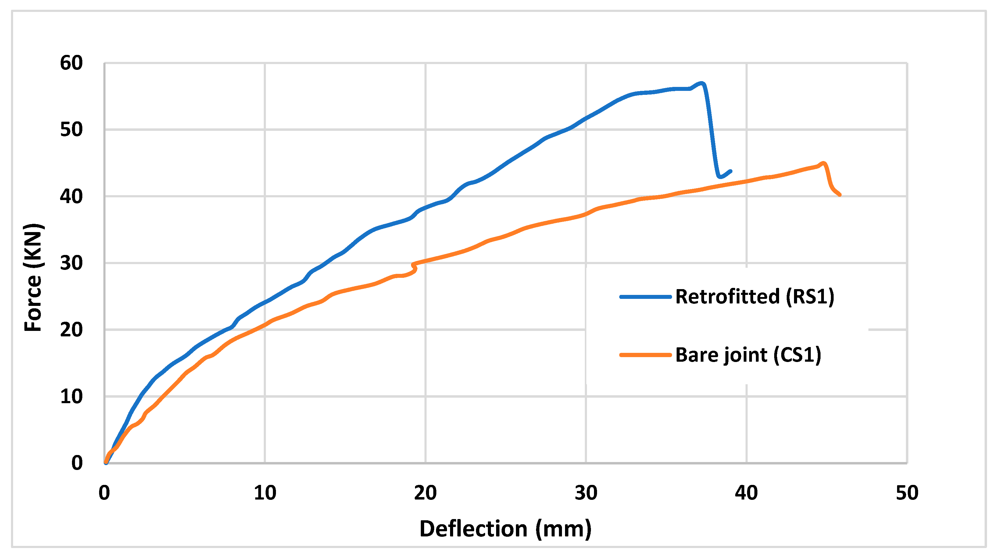
The control sample CS1, which bore no FRP, was tested monotonically to failure. The tip load versus displacement of the CS1 and RS1 is shown in Figure 4. The capability of the flange-bonded retrofit in enhancing capacity can be deduced from these curves. It is obvious that the response is almost linear up to 9 KN, at which load the first crack develops and the joint enters non-linear responses with a gradually decreasing stiffness as the load increases. The joint cracking is not visible at that load; it is only assumed from the shape of the force–displacement curve. The first flexural cracks of the beam initiate with the tip load of 20 KN, corresponding to a displacement of about 9 mm. Moreover, beam flexural cracks were raised at different locations off the column face as loading progressed. The longitudinal reinforcing of the beam yielded an ordinary load equal to 39 KN with an average yield displacement of 32 mm. The test was stopped at the load reached the joint’s peak capacity, which was almost 45 KN, corresponding to a 43.6 mm displacement. As the column was constantly subjected to a 150 kN load, the experimental test was halted when the beam’s resistance significantly dropped, primarily due to the development of severe cracks and the crushing of the compression area of the beam concrete, posing a safety concern.
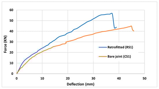
Figure 4.
Beam tip load versus tip displacement of the specimens (left side).
Consequently, the force–displacement graph has been plotted up to the point where the beam’s resistance reached its maximum, i.e., before experiencing a noticeable reduction in strength capacity. This peak resistance force is then used to determine the load-bearing capacity of the beam. Though loading was over, some flexural cracks were noticed to have been formed near the beam, close to the column face, and others had progressed into the beam (Figure 5a).
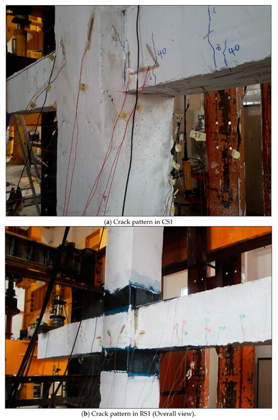
Figure 5.
Crack pattern after conducting an experimental test.
The test for case RS1 (retrofitted and strengthened by five 300 mm CFRP layers stretching from the column) was stopped when the load reached the joint’s peak capacity at 56.58 KN, which corresponded to a 38.4 mm displacement. As shown in Figure 5b, the beam failed, demonstrating ductile behavior right where FRP was cut off and sending the plastic hinge off the joint core.
No considerable debonding was experimentally observed in this research, which presents moderate ductility. Furthermore, Table 1 shows that the flange-bonded retrofit had increased the original frame capacity by 26%, while decreasing the displacement capacity by 17%. It is seen that the maximum bar strains at the end point of FRP in the longitudinal reinforcements are greater than the rebar yield strain.

Table 1.
Steel yield stress–plastic strain.
4. Numerical Model of the Retrofitted Joints
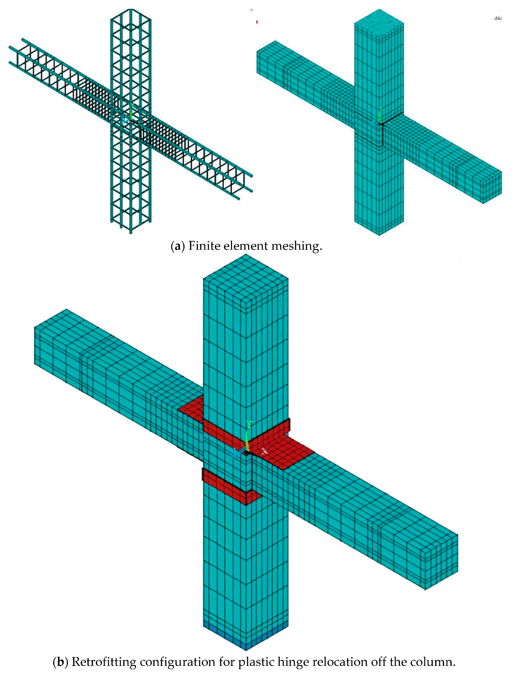
In this study a designed RC frame has been considered which has been used in the literature to investigate the effects of retrofitting joints via the CFRP web-bonded scheme [24,25,42]. The ANSYS 2019 R1 finite element software was used for modeling, as shown in Figure 6. In the finite element modeling process, the contact between the CFRP sheets and concrete is defined as the tie bonding since it is assumed that both concrete and CFRP sheets are properly bonded to each other using an adhesive. At each node of the elements, three degrees of freedom were considered, comprising eight-noded solid elements (possible translations in the nodal X-, Y-, and Z-directions). This element renders possible cracks in three orthogonal directions, plastic deformations, and crushing. Link180 element is used to model the steel reinforcements. A bi-linear curve with 2% post-yield strain hardening was used to represent the steel stress–strain relation. The steel plates were modeled at the hinge support by Solid185, which is a solid element with eight nodes.

Figure 6.
Finite element model of considered RC joints.
These elements were applied to undo the possibilities of cracks resulting from stress concentration. Eight nodes were assumed for these elements, each having the three DOFs. CFRP sheets were modeled using Solsh190, a solid-shell-type element with eight nodes. This type of element possesses the geometry of a continuum solid element at each node. Finally, the columns’ end was modeled considering suitable boundary conditions to apply an axial compression force at the joint throughout the analysis.
To perform the non-linear pushover analyses, stepwise equal and opposite loads were applied to the beams’ ends. The modified Newton–Raphson method was implemented to solve the pushover problem. However, the convergence criteria that were considered were based on displacement, whose tolerance limit was taken equal to the FE software. In order to conduct non-linear analysis, automatic time stepping in FE, which predicted and controls load steps, was used. The FE mesh of the joint retrofitted with the flange-bonded scheme is shown in Figure 6b.
Nearby, 3144 Solid65 elements were used to model concrete elements, while for the steel bars, 1363 Link180 elements were used, and CFRP sheets were modeled with 264 Solsh190 elements. Nonetheless, using the beam element instead of the link element for modeling steel bars may lead to more accurate outcomes by considering the bending behavior of the steel bars.
The mesh sensitivity analysis has been conducted to assess the effect of mesh size and the number of elements on the finite element analysis results. Therefore, the final analysis results were obtained from the most stable model, where changing mesh size did not affect the results by more than +/−1%.
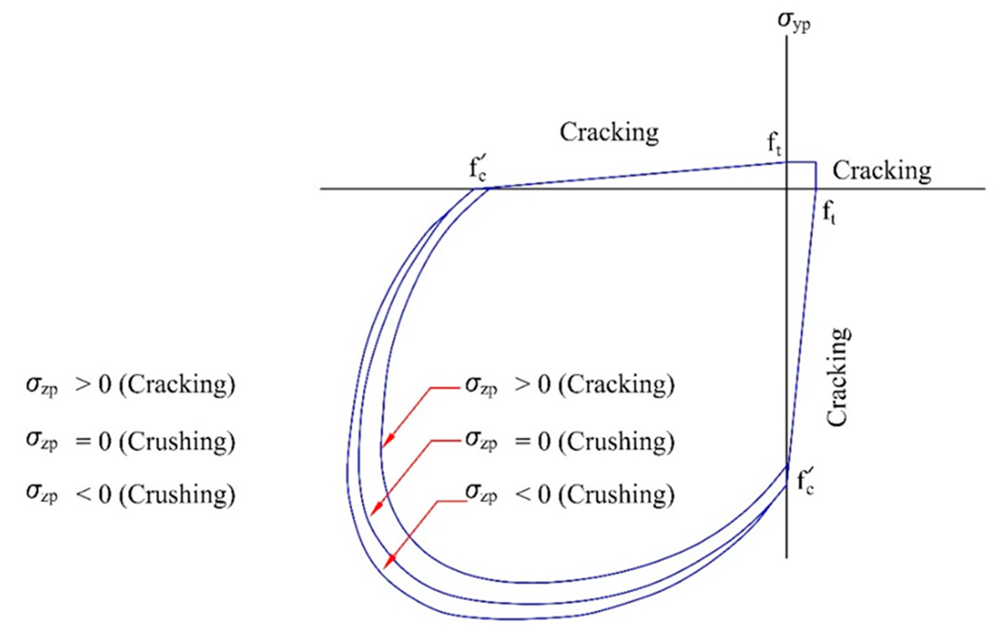
The William–Warnke model was employed to account for the failure criterion of concrete and cracking, as well as possible models of crushing failure [43]. Therefore, for failure surface failure, compressive strength and ultimate uniaxial tensile strength are required. Figure 7 shows a three-dimensional concrete failure surface [32]. It is seen that the stiffness of the cracked concrete vanishes in the FE model; hence, tension cannot be resisted.

Figure 7.
Three-dimensional failure surfaces based on William–Warnke criterion [3].
Since principal stresses are all compressive and lie outside of the failure surface, the concrete starts to crush; thus, the elastic modulus in all directions decreases rapidly. Additionally, β_(t) and β_c are coefficients of shear transfer with values between 0 and 1 introduced for the definition of concrete for open and closed cracks. The value of “0” represents a smooth crack (i.e., complete loss of shear transfer), and “1” stands for a rough crack (i.e., no loss of shear transfers). β_(t) is the shear transfer coefficient, taken as 0.25 for open cracks, and β_c was taken as 0.99 for closed cracks [44,45].
The efficiency of CFRP depends on several parameters, including the number of fibers, mechanical properties, surface preparation, and debonding [46,47]. The latter is a major issue with which numerous CFRP applications are associated. The maximum CFRP strain allowed for the elimination of this mode of failure, which is the result of intermediate cracks, and it is limited to the value suggested by ACI 440.2-08.
4.1. Model Validation
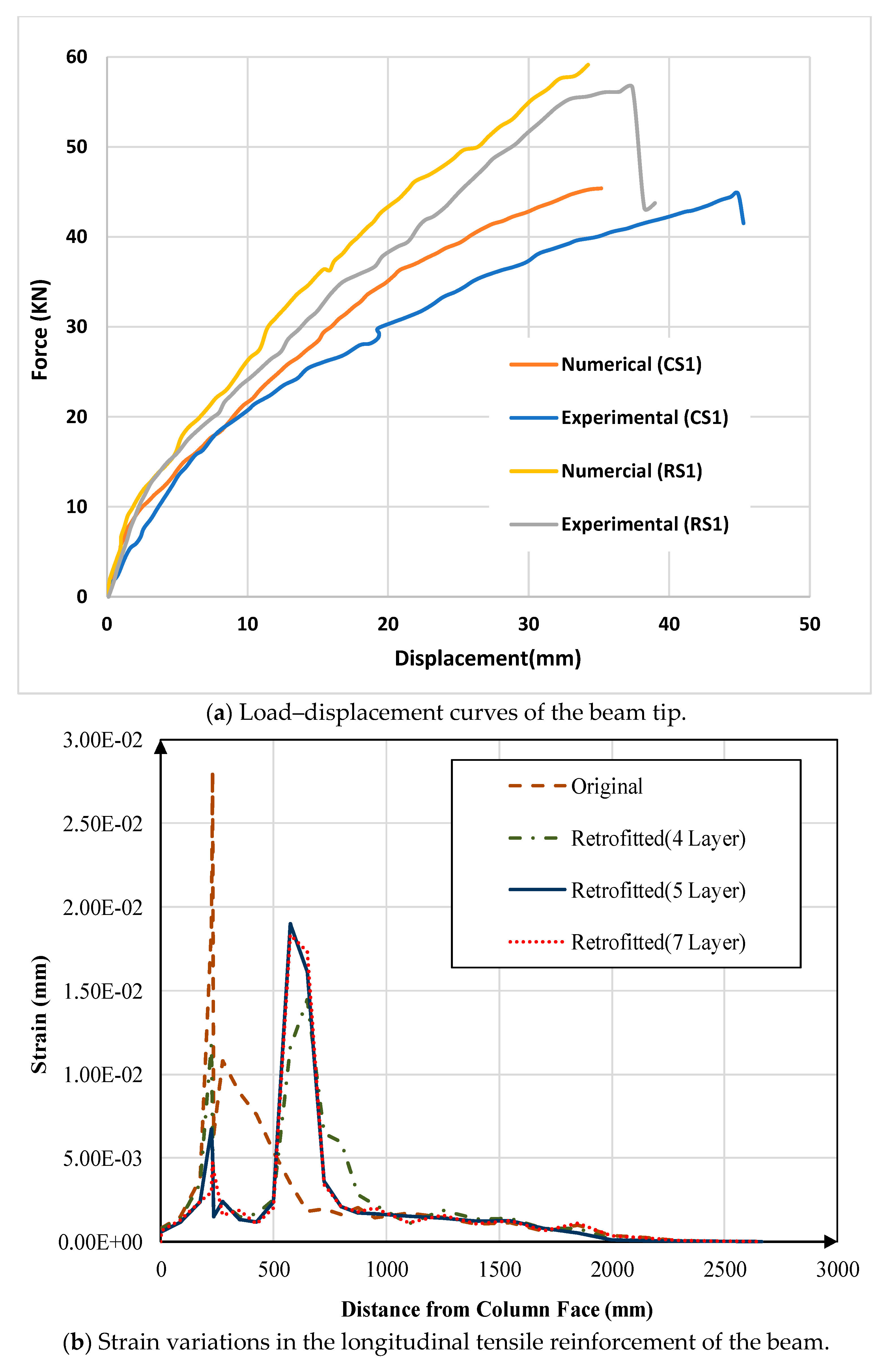
The numerical model was verified by extracting the load–displacement results of the beam through the FE analysis. As shown in Figure 8a, the comparison was made with the experimental testing output, and the results showed very close agreement, confirming the verification for both CS1 and RS1 models. As expected, the FE numerical solution resulted in a stiffer response for both models, showing higher initial stiffness. Following the expected initial discrepancy, trends of the numerical and experimental curves are similar up to 20 KN, followed by a stiffer response from the finite element model. However, the numerical analysis predicts the ultimate capacity relatively accurately, with a slightly higher resistant force, proving that the FE model and the performed analysis were reliable for both considered models (before and after retrofitting).
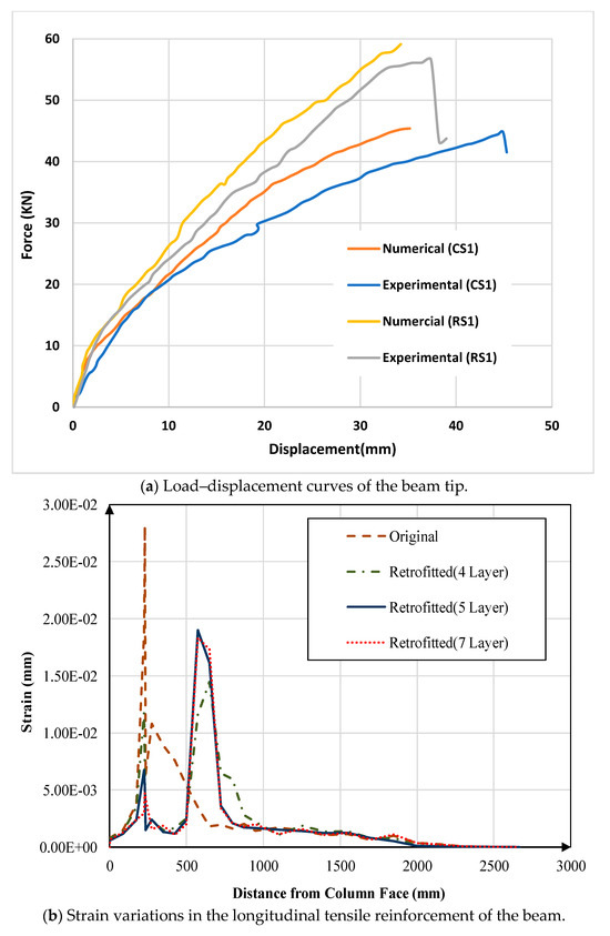
Figure 8.
Load–displacement and strain results.
Accordingly, the results presented in the graph of Figure 8a depict that the maximum strength achieved for both CS1 and RS1 joints through finite element analysis was 45.4 kN and 59.13 kN, respectively. In comparison, the maximum strength capacity for these joints obtained from the experimental tests was 44.8 kN and 56.5 kN, respectively. Therefore, these results validate the FEM simulation with a 1.2% error for CS1 and a 4.3% error for RS1. The higher error for the frame retrofitted with CFRP is mostly due to the assumption of full bonding between CFRP and concrete during FEM modeling, which is unlikely to occur in practical construction operations. To increase the accuracy of the results, it is recommended to insert the action of an adhesive in the model by using proper contact elements or interface elements to simulate the realistic behavior of CFRP and concrete bonding.
4.2. Pushover Analysis of the Retrofitted Connection
Once the numerical model was validated, the CFRP-retrofitted RC joint was analyzed. As stated earlier, the target of this research was to evaluate the ability of the selected CFRP retrofit scheme by shifting the place of the plastic hinges off the column face. However, the selected flange-bonded retrofitting scheme is shown in Figure 6b. In a parametric study, the thickness and number of CFRP sheets required for a successful plastic hinge relocation into the beam were to be determined.
To this end, the non-linear pushover analysis of the joint was performed using different CFRP overlay thicknesses, and for each thickness, the strain state in the beam’s tensile reinforcements was considered for locating the true position of the plastic hinge. The joint was then retrofitted with 4, 5, and 7 layers of CFRP laminates, corresponding, respectively, to thicknesses of 0.66 mm, 0.825 mm, and 1.155 mm. As shown in Figure 8b, the maximum strain variation in the longitudinal tensile reinforcements of the beam retrofitted with 4, 5, and 7 layers of CFRP is compared with reinforcement strain variation in the original (non-retrofitted) beam.
Moreover, Figure 8b demonstrates that for the original joint, the maximum strain in steel reinforcement corresponding to plastic hinge location occurs in the vicinity of the column. While the connection is retrofitted using four layers of laminates, there will be two peaks, one close to the column and the other at the end section of CFRP sheets. These two peaks are close in value; it cannot be stated that a safe relocation of the plastic hinge has followed. However, once five layers of CFRP sheets are used to retrofit the joint, the reinforcement strain at the end of the CFRP overlay evidently dominates the strain formed at the column face. This indicates a successful relocation of the hinge over the cover. Higher numbers of CFRP layers would also lead to such relocation, and the retrofitting would then be more expensive. Therefore, for this joint, a five-layer coat is considered as the optimal thickness for successful plastic hinge relocation.
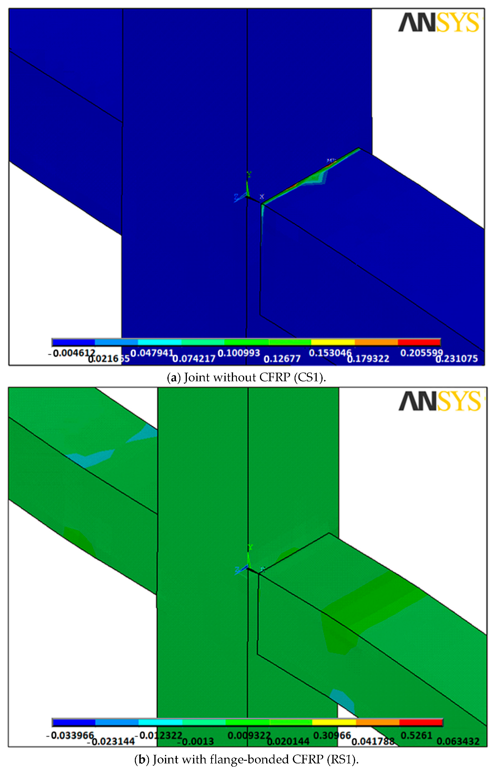
The joint stress variation and concrete strain contours when the applied load reaches its ultimate level before and after retrofitting are displayed in Figure 9 and Figure 10, respectively. These figures also show the relocation of the plastic hinge due to retrofitting.

Figure 9.
Stress contours of the joint and successful relocation of maximum stress from joint area to the beam length.
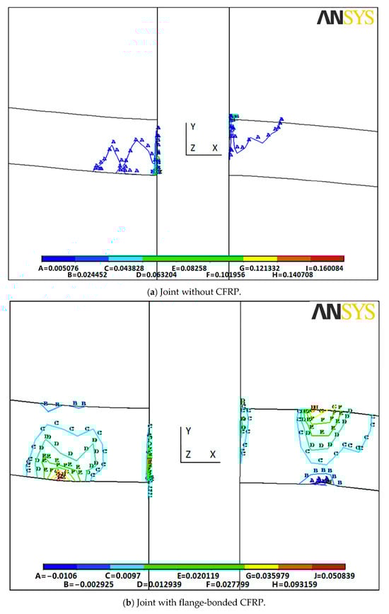
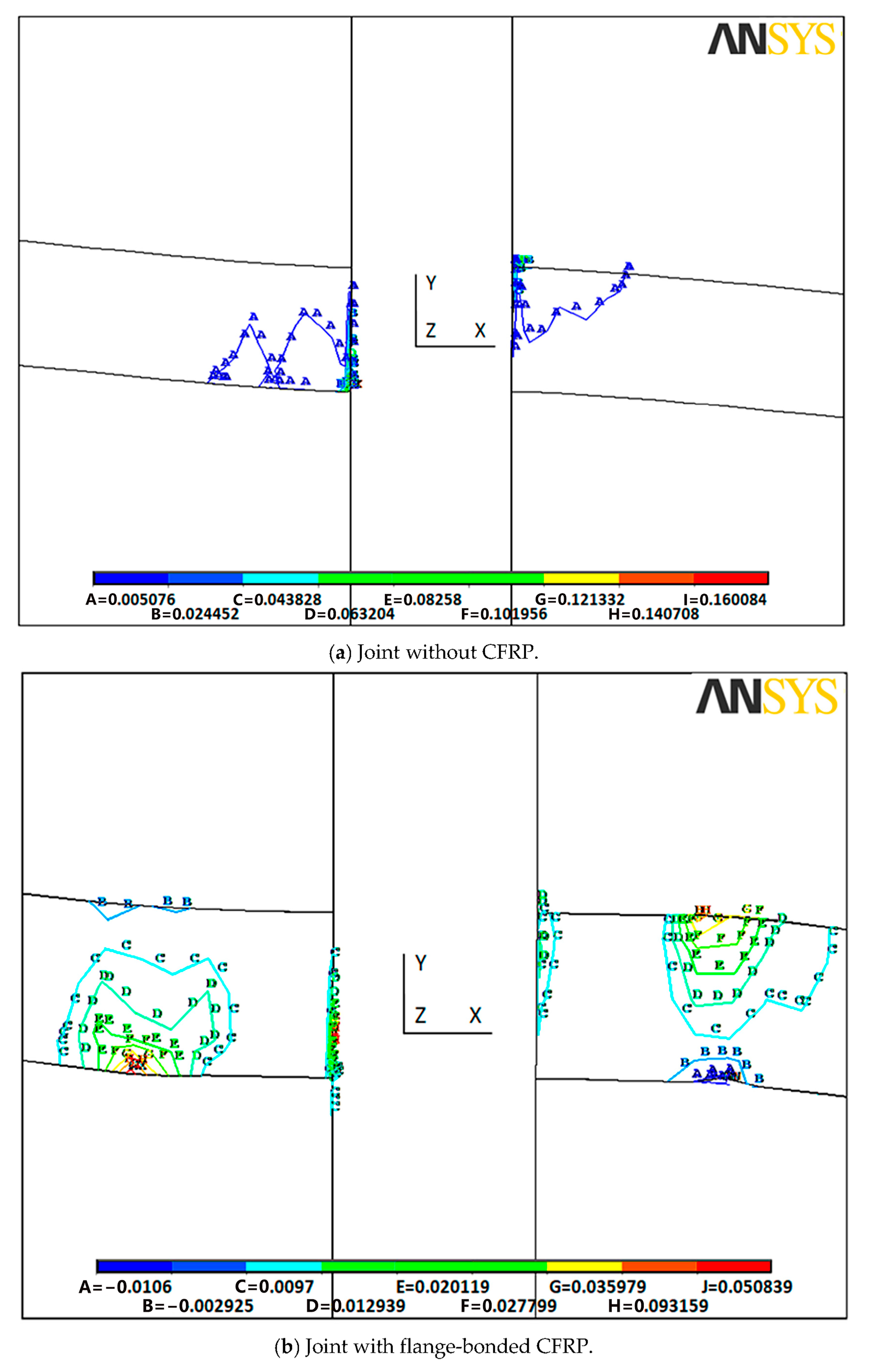
Figure 10.
Strain contours of the joint.
In Figure 9, the stress counter indicates that in the control sample (CS1), the maximum stress under applied loads appears at the contact point of the beam–column, specifically at the top part of the beam. However, in the retrofitted joint (RS1), the peak stress occurs in the beam, away from the beam–column connection surface. These results reveal that bonding the flange with CFRP leads to a shift in the position of the peak stress from the beam–column contact point to a location along the beam length, away from the joint.
Similarly, in Figure 10, the strain counter shows that in the CS1 joint, the maximum strain (deformation) appears at the contact surface of the beam–column in the tensile part (top of the right beam and bottom of the left beam). Hence, in the RS1 joint, the peak strain and consequent plastic hinges are observed to occur in the beams, away from the beam–column connection. These results demonstrate that by employing the proposed retrofitting technique, the position of plastic hinge occurrence has successfully shifted from the near beam–column connection face to the beam length at a further distance from the joint area. Therefore, the beam–column joint is able to function during applied loads and provide structural integrity and stability.
However, practically, in order to appropriately design for retrofitting scheme by using flange-bonded CFRP layers, it is recommended to add a large enough number of CFRP layers in the critical length of the beam beside the joint (preferably equal to the depth of the beam) in order to relocate the plastic hinge from the joint area to the length of the beam which is not critical for the stability of the structure. The number of CFRP layers can be estimated based on the amount of imposed shear force and bending moment at the beam and column in the joint.
5. Conclusions
In this study, a new retrofitting scheme involving flange-bonded CFRP was investigated via numerical and experimental investigations of RC beam–column joints. First, the FE method was employed for our numerical study. To ensure the experimental testing setup accorded with real structural conditions under actual loading, a constant load was applied to the top of the column, thus reflecting the dead load on the column of the RC frame. Meanwhile, a couple of forces were incrementally applied at the end of the beams via two jacks to generate a double curvature action in the beam–column joint, which would occur during the application of vertical and lateral loads to the frame. Since the primary goal of this research was to relocate the plastic hinges from the column face to a greater length along the beam, the results of the experimental tests and numerical analyses demonstrate that the proposed retrofitting scheme successfully achieves this objective. By employing this retrofitting approach, plastic hinges are now observed at a considerable distance from the column faces. This significantly enhances the safety and security of the beam–column joint when the structure is subjected to seismic excitations, ultimately ensuring the stability and integrity of the structure. However, the most important experimental and numerical model findings can be summarized as follows.
Experiments and numerical results show that under static loads under a moderate-ductility RC, beam plastic hinges may be present near the column face. Thus, the flange-bonded scheme in this study is practical and can be used in actual 3D frames as it takes the presence of the cross beams into consideration and accounts for the integrated floor slabs.
- The experimental configuration suggested a significant rise in the connection’s ultimate strength (26%).
- Inelastic deformations took place 300 mm to 400 mm off the column, meaning the required relocation has been achieved.
- Five CFRP layers were considered as the ideal thickness for successful plastic hinge relocation.
- Higher numbers of CFRP layers would also lead to such a relocation, and the retrofitting would then be more expensive.
- The experimental and numerical results confirmed the effectiveness of the suggested grooving method. It is believed that the flange-bonded CFRP retrofitting improves the capacity of the joints. This proved its ability to send the possible plastic hinge off the joint and further into the beam, leading to a ductility increase and an improvement of the overall RC frame performance.
- Finally, the results of the successfully conducted experiments and numerical testing indicate that under the condition of seismic loading in a moderate-ductility-reinforced concrete-moment-resisting frame, beam plastic hinges might materialize near the column face.
Author Contributions
Conceptualization, F.H., R.A. and A.A.F.; Methodology, F.H., R.A. and A.A.F.; Software, R.A. and A.A.F.; Formal analysis, R.A. and A.A.F.; Investigation, R.A. and A.A.F.; Resources, F.H.; Data curation, R.A. and A.A.F.; Writing—original draft, R.A. and A.A.F.; Writing—review and editing, F.H.; Visualization, R.A. and A.A.F.; Supervision, F.H.; Project administration, F.H.; Funding acquisition, F.H. All authors have read and agreed to the published version of the manuscript.
Funding
This research received no external funding.
Institutional Review Board Statement
Not applicable.
Informed Consent Statement
Not applicable.
Data Availability Statement
All new data created through this study are already included in this paper. Therefore, data sharing is not applicable to this article.
Conflicts of Interest
The authors declare no conflict of interest.
References
- Ali, H.T.; Akrami, R.; Fotouhi, S.; Bodaghi, M.; Saeedifar, M.; Yusuf, M.; Fotouhi, M. Fiber reinforced polymer composites in bridge industry. Structures 2021, 30, 774–785. [Google Scholar] [CrossRef]
- Harries, K.A. ASCE 41 Seismic Assessment of FRP-Repaired Concrete Columns. J. Compos. Constr. 2021, 25, 04021001. [Google Scholar] [CrossRef]
- Yazdani, S.; Asadollahi, S.; Shoaei, P.; Dehestani, M. Failure stages in post-tensioned reinforced self-consolidating concrete slab strengthened with CFRP layers. Eng. Fail. Anal. 2021, 122, 105219. [Google Scholar] [CrossRef]
- Liang, S.-L.; Fu, F.; Huang, Z.-Q.; Qian, K. Enhancement of collapse-resistant capacity of non-seismically designed RC frames using various CFRP strengthening schemes. Eng. Struct. 2023, 291, 116450. [Google Scholar] [CrossRef]
- Alkhawaldeh, A.A.; Alrousan, R.Z. Improving cyclic response of heat-damaged non-ductile RC joints using CFRP hybrid systems. Constr. Build. Mater. 2023, 377, 131150. [Google Scholar] [CrossRef]
- Farahbod, F.; Aalam, H.; Jahanmohammadi, A. Seismic behavior of three-dimensional interior reinforced concrete beam–column joints strengthened with CFRP sheets. Asian J. Civ. Eng. 2023, 1–18. [Google Scholar] [CrossRef]
- Farhang, K.; Farahbod, F.; Nezamabadi, M.F.; Mansouri, B. Shear strengthening of RC 3D exterior beam-column joints with CFRP sheets an experimental and numerical study. Asian J. Civ. Eng. 2023, 24, 1599–1619. [Google Scholar] [CrossRef]
- Fayaz, Q.; Kaur, G.; Bansal, P.P. Numerical Modelling of Seismic Behaviour of an Exterior RC Beam Column Joint Strengthened with UHPFRC and CFRP. Arab. J. Sci. Eng. 2021, 47, 4971–4986. [Google Scholar] [CrossRef]
- Hajirasouliha, I.; Doostan, A. A simplified model for seismic response prediction of concentrically braced frames. Adv. Eng. Softw. 2010, 41, 497–505. [Google Scholar] [CrossRef]
- Shen, X.; Li, B.; Chen, Y.-T.; Tizani, W. Seismic performance of reinforced concrete interior beam-column joints with novel reinforcement detail. Eng. Struct. 2021, 227, 111408. [Google Scholar] [CrossRef]
- Haridas, A.P.; Mathai, A. Plastic Hinge Relocation in RCC Double-Slotted Beam Connection. In Advances in Civil Engineering; Springer: Singapore, 2020; pp. 715–724. [Google Scholar]
- Ercan, E.; Arisoy, B.; Ertem, O.B. Experimental Assessment of RC Beam-Column Connections with Internal and External Strengthening Techniques. Adv. Civ. Eng. 2019, 2019, 2828353. [Google Scholar] [CrossRef]
- Ghobarah, A.; Said, A. Shear strengthening of beam-column joints. Eng. Struct. 2002, 24, 881–888. [Google Scholar] [CrossRef]
- Parvin, A.; Granata, P. Investigation on the effects of fiber composites at concrete joints. Compos. Part B Eng. 2000, 31, 499–509. [Google Scholar] [CrossRef]
- Granata, P.J.; Parvin, A. An experimental study on Kevlar strengthening of beam–column connections. Compos. Struct. 2001, 53, 163–171. [Google Scholar] [CrossRef]
- Li, J.; Samali, B.; Ye, L.; Bakoss, S. Behaviour of concrete beam–column connections reinforced with hybrid FRP sheet. Compos. Struct. 2002, 57, 357–365. [Google Scholar] [CrossRef]
- Obaidat, Y.T. Cyclic behavior of interior RC beam-column joints strengthened with NSM-CFRP ropes. Structures 2022, 37, 735–744. [Google Scholar] [CrossRef]
- Farhang, K.; Farahbod, F.; Nezamabadi, M.F. Hysteresis behavior of 3D RC exterior beam-column joints strengthened with CFRP sheets and spike anchors. Structures 2022, 40, 1065–1077. [Google Scholar] [CrossRef]
- Attari, N.; Amziane, S.; Chemrouk, M. Efficiency of Beam–Column Joint Strengthened by FRP Laminates. Adv. Compos. Mater. 2010, 19, 171–183. [Google Scholar] [CrossRef]
- Wang, B.; Wu, X.; Liu, Q.; Wu, Y.; Huang, F.; Xu, L.; Wu, X.; Deng, Y. Effectiveness and Efficiency of Externally Bonded CFRP Sheets for Shear Strengthening of RC Beam-Column Joints. Polymers 2022, 14, 1347. [Google Scholar] [CrossRef]
- De Vita, A.; Napoli, A.; Realfonzo, R. Full Scale Reinforced Concrete Beam-Column Joints Strengthened with Steel Reinforced Polymer Systems. Front. Mater. 2017, 4, 18. [Google Scholar] [CrossRef]
- Antonopoulos, C.P.; Triantafillou, T.C. Experimental Investigation of FRP-Strengthened RC Beam-Column Joints. J. Compos. Constr. 2003, 7, 39–49. [Google Scholar] [CrossRef]
- Le-Trung, K.; Lee, K.; Lee, J.; Lee, D.H.; Woo, S. Experimental study of RC beam–column joints strengthened using CFRP composites. Compos. Part B Eng. 2010, 41, 76–85. [Google Scholar] [CrossRef]
- Niroomandi, A.; Maheri, A.; Maheri, M.R.; Mahini, S. Seismic performance of ordinary RC frames retrofitted at joints by FRP sheets. Eng. Struct. 2010, 32, 2326–2336. [Google Scholar] [CrossRef]
- Maheri, M.R.; Akbari, R. Seismic behaviour factor, R, for steel X-braced and knee-braced RC buildings. Eng. Struct. 2003, 25, 1505–1513. [Google Scholar] [CrossRef]
- Naser, M.Z.; Hawileh, R.A.; Abdalla, J. Modeling Strategies of Finite Element Simulation of Reinforced Concrete Beams Strengthened with FRP: A Review. J. Compos. Sci. 2021, 5, 19. [Google Scholar] [CrossRef]
- Mahdavipour, M.A.; Eslami, A.; Jehel, P. Seismic evaluation of ordinary RC buildings retrofitted with externally bonded FRPs using a reliability-based approach. Compos. Struct. 2019, 232, 111567. [Google Scholar] [CrossRef]
- Huang, Q.; Liu, Y.; Shi, M. Experimental study on seismic performance of RC exterior beam-column joints strengthened by annular CFRP sheets wrapping. J. Build. Struct. 2022, 43, 76. [Google Scholar]
- Seifi, A.; Hosseini, A.; Marefat, M.S.; Zareian, M.S. Improving seismic performance of old-type RC frames using NSM technique and FRP jackets. Eng. Struct. 2017, 147, 705–723. [Google Scholar] [CrossRef]
- Allam, K.; Mosallam, A.S.; Salama, M.A. Experimental evaluation of seismic performance of interior RC beam-column joints strengthened with FRP composites. Eng. Struct. 2019, 196, 109308. [Google Scholar] [CrossRef]
- Jawdhari, A.; Fam, A.; Harik, I. Bond between CFRP rod panels and concrete using cementitious mortar. Constr. Build. Mater. 2020, 235, 117503. [Google Scholar] [CrossRef]
- Basim, S.; Hejazi, F.; Rashid, R.S.B.M. Embedded carbon fiber-reinforced polymer rod in reinforced concrete frame and ultra-high-performance concrete frame joints. Int. J. Adv. Struct. Eng. 2019, 11, 35–51. [Google Scholar] [CrossRef]
- Maheri, M.R.; Torabi, A. Retrofitting external RC beam-column joints of an ordinary MRF through plastic hinge relocation using FRP laminates. Structures 2019, 22, 65–75. [Google Scholar] [CrossRef]
- Akhlaghi, A.; Mostofinejad, D. Experimental and analytical assessment of different anchorage systems used for CFRP flexurally retrofitted exterior RC beam-column connections. Structures 2020, 28, 881–893. [Google Scholar] [CrossRef]
- Zhu, Y.; Chen, Y.; He, K.; Feng, R.; Zhang, X.; Zhu, Q.; Tang, C. Flexural behavior of concrete-filled SHS and RHS aluminum alloy tubes strengthened with CFRP. Compos. Struct. 2020, 238, 111975. [Google Scholar] [CrossRef]
- Arowojolu, O.; Ibrahim, A. Plastic hinge relocation in exterior reinforced beam–column joint and compliance issues to seismic design guidelines—A review. Struct. Concr. 2020, 21, 1938–1958. [Google Scholar] [CrossRef]
- Mosallam, A.; Allam, K.; Salama, M. Analytical and numerical modeling of RC beam-column joints retrofitted with FRP laminates and hybrid composite connectors. Compos. Struct. 2019, 214, 486–503. [Google Scholar] [CrossRef]
- Khan, M.S.; Basit, A.; Ahmad, N. A simplified model for inelastic seismic analysis of RC frame have shear hinge in beam-column joints. Structures 2021, 29, 771–784. [Google Scholar] [CrossRef]
- Al-Rousan, R.Z.; Alhassan, M.A.; Al-Omary, R.J. Response of interior beam-column connections integrated with various schemes of CFRP composites. Case Stud. Constr. Mater. 2021, 14, e00488. [Google Scholar] [CrossRef]
- El-Zeadani, M.; Saifulnaz, M.R.; Hejazi, F.; Amran, Y.M.; Jaafar, M.; Alyousef, R.; Alrshoudi, F. Mechanics-based approach for predicting the short-term deflection of CFRP plated RC beams. Compos. Struct. 2019, 225, 111169. [Google Scholar] [CrossRef]
- Saqan, E.I.; Rasheed, H.A.; Hawileh, R.A. An efficient design procedure for flexural strengthening of RC beams based on ACI 440.2R-08. Compos. Part B Eng. 2013, 49, 71–79. [Google Scholar] [CrossRef]
- Azarm, R.; Maheri, M.R.; Torabi, A. Retrofitting RC Joints Using Flange-Bonded FRP Sheets. Iran. J. Sci. Technol. Trans. Civ. Eng. 2017, 41, 27–35. [Google Scholar] [CrossRef]
- Zarandi, S.; Maheri, M.R. Seismic performance of RC frames retrofitted by FRP at joints using a flange-bonded scheme. Iran. J. Sci. Technol. Trans. Civ. Eng. 2015, 39, 103. [Google Scholar]
- Soudki, K.; Alkhrdaji, T. Guide for the design and construction of externally bonded FRP systems for strengthening concrete structures (ACI 440.2R-02). In Proceedings of the Structures Congress 2005: Metropolis and Beyond, New York, NY, USA, 20–24 April 2005; pp. 1–8. [Google Scholar]
- Paulay, T.; Priestley, M.N. Seismic Design of Reinforced Concrete and Masonry Buildings; John Wiley & Sons: Hoboken, NJ, USA, 1992. [Google Scholar]
- Nguyen-Minh, L.; Phan-Vu, P.; Tran-Thanh, D.; Truong, Q.P.T.; Pham, T.M.; Ngo-Huu, C.; Rovňák, M. Flexural-strengthening efficiency of cfrp sheets for unbonded post-tensioned concrete T-beams. Eng. Struct. 2018, 166, 1–15. [Google Scholar] [CrossRef]
- Sojobi, A.O.; Liew, K.M. Flexural behaviour and efficiency of CFRP-laminate reinforced recycled concrete beams: Optimization using linear weighted sum method. Compos. Struct. 2020, 260, 113259. [Google Scholar] [CrossRef]

Disclaimer/Publisher’s Note: The statements, opinions and data contained in all publications are solely those of the individual author(s) and contributor(s) and not of MDPI and/or the editor(s). MDPI and/or the editor(s) disclaim responsibility for any injury to people or property resulting from any ideas, methods, instructions or products referred to in the content. |
© 2023 by the authors. Licensee MDPI, Basel, Switzerland. This article is an open access article distributed under the terms and conditions of the Creative Commons Attribution (CC BY) license (https://creativecommons.org/licenses/by/4.0/).