Abstract
In this paper, a model based on constraint convex optimization is proposed for the radiation pattern synthesis in cylindrical and spherical microstrip conformal array antennas. The optimization algorithm is modeled to decrease the Euclidean distance between the obtained radiation pattern of the deformed array and the desired radiation pattern of the planar array by calculating the suitable amplitude and phase values for the individual array patches. Four prototypes of , , , and microstrip patch array antenna are used as the radiating elements which are deformed from planar arrangement and placed on the faces of prescribed spherical and cylindrical shapes with various radii of curvatures. The results reveal that the performance of optimization algorithm performs better in array, followed by array, array, and array. However, array provides more degrees of freedom for tuning the radiation pattern in desired form. The array computes suitable amplitude and phase values for the radiating elements of the array, which restore the radiation pattern in terms of mainlobe reconstruction, null locations, sidelobe levels, up to the deformation of in both spherical and cylindrical configurations of conformal array. The proposed optimization technique when applied to conformal antenna array offers fast computational speed and good convergence accuracy for radiation pattern synthesis, which can be useful for various engineering applications.
1. Introduction
Conformal arrays can also be used in 5G applications to improve the performance and efficiency of wireless communication systems [1]. Indeed, 5G networks require a high density of small cells, which can be challenging to deploy in urban environments. Conformal arrays can help by providing compact and adaptable antennas that can be easily integrated into existing infrastructure, such as lamp posts or building facades. One of the main advantages of conformal arrays in 5G applications is their ability to provide directional coverage [2]. With beamforming capabilities, the arrays can steer the signal towards a specific area or user, increasing the signal strength and improving the overall network capacity. Conformal arrays are a type of antenna array that are designed to conform to the surface of a particular structure or platform, such as an aircraft, vehicle, or building. This means that instead of having a traditional flat or planar antenna array, the conformal array is shaped to fit the curvature of the structure it is mounted on, resulting in improved aerodynamics and reduced radar cross-section. Conformal arrays can use digital signal processing techniques to steer and shape the beam in multiple directions, even in real time. The combination of the conformal design and beamforming capabilities make these arrays well-suited for a variety of applications, including military and aerospace systems where high performance and low visibility are critical. They can also be used in commercial applications, such as for wireless communication or radar systems [3].
Antenna surface deformation significantly deteriorates the radiation performance of an antenna [4]. When an antenna is designed, its surface shape is carefully engineered to achieve specific radiation properties, such as beam pattern, polarization, and gain. Any deformation of the surface can cause changes in these properties, which can lead to a degradation of the antenna’s performance. One common effect is the variation in the resonant frequency of antenna. This can occur when the deformation alters the physical measurements of the antenna, which in turn changes its resonant frequency. As a result, the antenna may no longer be optimized for the frequency at which it is intended to operate. Another effect of surface deformation is a change in the antenna’s radiation pattern including sidelobe level (SSL) elevation, broadside beam divergence, nulls positioning alteration, and lower antenna gain. In order to moderate this surface deformation effect, it is important to include an adaptive pattern synthesis capability system in the antenna array, which can correct for the distortion and maintain the desired radiation pattern. This paper examines the impact of static deformation for several configuration of cylindrical and spherical structures of conformal array antenna, which is deformed from planar configuration.
Radiation pattern synthesis in conformal array antennas is usually more complex as compared to planar arrays. This involves designing and optimizing the radiation pattern of the antenna to meet specific performance goals [5]. The radiation pattern describes the directional characteristics of the antenna’s electromagnetic field, and the optimization process involves adjusting the position, orientation, and phase of the antenna elements to achieve the desired pattern. The main goal of synthesizing the array pattern in conformal arrays is to attain the desired radiation pattern through adjusting the mutual coupling effect, weight excitations, and polarization information of the array. In literature, a variety of methods and algorithms has been employed to resolve the synthesis problem for radiation pattern correction in conformal array antennas. In mechanical correction techniques, the compensation algorithm synthesizes the radiation pattern by adaptively changing the contour of the array surface and the location of the radiating elements with the help of mechanical beam steering conformal transmitarray [6], mechanical translation of the parasitic elements [7], driving mechanism, dielectric elastomer actuator [8], tuning of antennas with mechanical action [9], and employing electro-active polymers to adjust the antenna pattern [10]. However, these techniques demand sophisticated control strategies, micro servos, additional mounting space, sustainable power supply, and have a limited accuracy for the adjustment of radiation pattern with slow reaction time. Compared to the mechanical techniques, the electrical correction techniques correct the radiation pattern with high accuracy, in lesser time, and without the need of mechanical adjustments in the array. To compensate the field distortion, a variety of numerical methods and optimization algorithms has been used to optimize the field pattern in phased array antennas owing to the computer hardware limitations. These optimization methods include several evolutionary and probabilistic techniques that iteratively look-up and adjust the parameters determining the best-fitted results. For example: Method of moments [11]: This is a numerical method that solves Maxwell’s equations to compute the antenna’s radiation pattern. The method involves discretizing the antenna’s surface into small segments and solving for the electric and magnetic fields at each segment. The resulting system of equations is then solved to obtain the current distribution on the antenna surface, which is used to compute the radiation pattern. Geometric optimization [12]: This technique involves optimizing the shape and size of the antenna elements in the array to achieve the desired field patterns. Genetic algorithms [13]: These are optimization algorithms that use a population-based approach to search for the optimal antenna design. The algorithm generates a population of potential antenna designs, evaluates their radiation patterns, and then selects the best designs for further iteration. The algorithm continues until the best radiation pattern is achieved. Particle swarm optimization [14]: This is another optimization algorithm that simulates the behavior of a group of particles in a search space. The particles move through the search space to evaluate the optimum solutions, guided by their own experience and the experience of the other particles in the swarm. The algorithm continues until the best radiation pattern is achieved. Finite element method [15]: This numerical method solves the partial differential equations of electromagnetics to compute the antenna’s radiation pattern. The method involves discretizing the antenna’s volume into small cells and solving for the electric and magnetic fields at each cell. The resulting system of equations is then resolved to acquire the current distribution on the surface of antenna, which is used to calculate the field patterns. Once the optimal radiation pattern has been synthesized, the antenna elements are positioned and oriented to achieve the desired pattern. This involves selecting the appropriate phase and amplitude for each antenna element to create constructive and destructive interference, shaping the radiation pattern in the desired direction. Simulated annealing [16]: This technique is a stochastic optimization method that involves iteratively searching for the global minimum of a cost function by randomly changing the antenna element positions. The algorithm accepts moves that increase the cost function with a probability that decreases over time. This technique has been used successfully in conformal array synthesis, but it can be computationally expensive. Neural networks [17]: This technique involves training a neural network to obtain the relationship between the antenna element positions and the radiation pattern. Once trained, the network can be utilized to make predictions about the radiation pattern for new antenna element positions. This technique has been shown to be effective for conformal array synthesis, but it requires a large amount of training data.
The performance of large, phased array antennas is scanned using an active element pattern method developed in [18], which accounts for all the mutual coupling effects to correct the field patterns of the array. Similar approach of using active element pattern method has been followed in [19,20,21] to synthesis the radiation pattern in conformal arrays. Reference [22] introduces a technique to mitigate random errors in amplitude and phase excitations of array elements, which can disrupt radiation patterns by clustering array elements and discretizing amplitude excitations to restore the desired patterns. Convex optimization theory is applied into the synthesis of conformal arrays with matched dual-polarized patterns, highlighting the importance of achieving polarization compatibility in spherical and cylindrical arrays design [23]. In [24], iterative convex optimization is applied to attain optimal difference patterns for 3D conformal beam-scanning arrays, with a specific focus on addressing the design challenges posed by hemispherical and conical conformal arrays featuring asymmetric radiation apertures. An iterative procedure that linearizes the non-convex power pattern function is used to solve the synthesis problem for narrowband conformal arrays in which the beam pattern synthesis is performed using second-order cone programming (SOCP) that results in a convex subproblem considering the magnitude constraints [25]. In [26], a projection technique is employed to determine the phase and amplitude distribution analytically, resulting in low sidelobe levels for spherical arrays. The projection method is further analyzed in mutually coupled phased arrays for radiation pattern correction in [27,28,29].
In conclusion, it has been demonstrated that various correction methods, signal processing techniques, sensor electronics, and amplitude and phase modifications can all be applied to optimize the radiation pattern of a conformal antenna array.
In particular, the paper describes a constraint convex optimization algorithm for the radiation pattern synthesis in cylindrical and spherical microstrip conformal array antennas. The goal of this optimization technique is to reduce the impact of surface deformations of the conformal array by finding the accurate weight excitations (phase and amplitude values) of the array elements. The optimization model is designed to use the convex optimization framework while incorporating constraints on the field pattern. This involves formulating an objective function that minimizes the Euclidean distance between the obtained radiation patterns of the deformed arrays and the desired radiation pattern of the planar array, while also controlling the mainlobe direction, null locations, and also the sidelobe levels. By formulating the optimization problem with appropriate constraints, the weights (amplitudes and phases) for the antenna radiating patches can be determined that will produce the radiation pattern in the deformed array nearly similar to the radiation pattern obtained in planar array. Four prototypes of , , , and microstrip patch array antenna are used as the radiating elements—which are bent from the planar configuration to the prescribed spherical and cylindrical shapes with several radii of curvatures—are evaluated to determine the effectiveness of the proposed optimization algorithm.
2. Array Factor Formulation
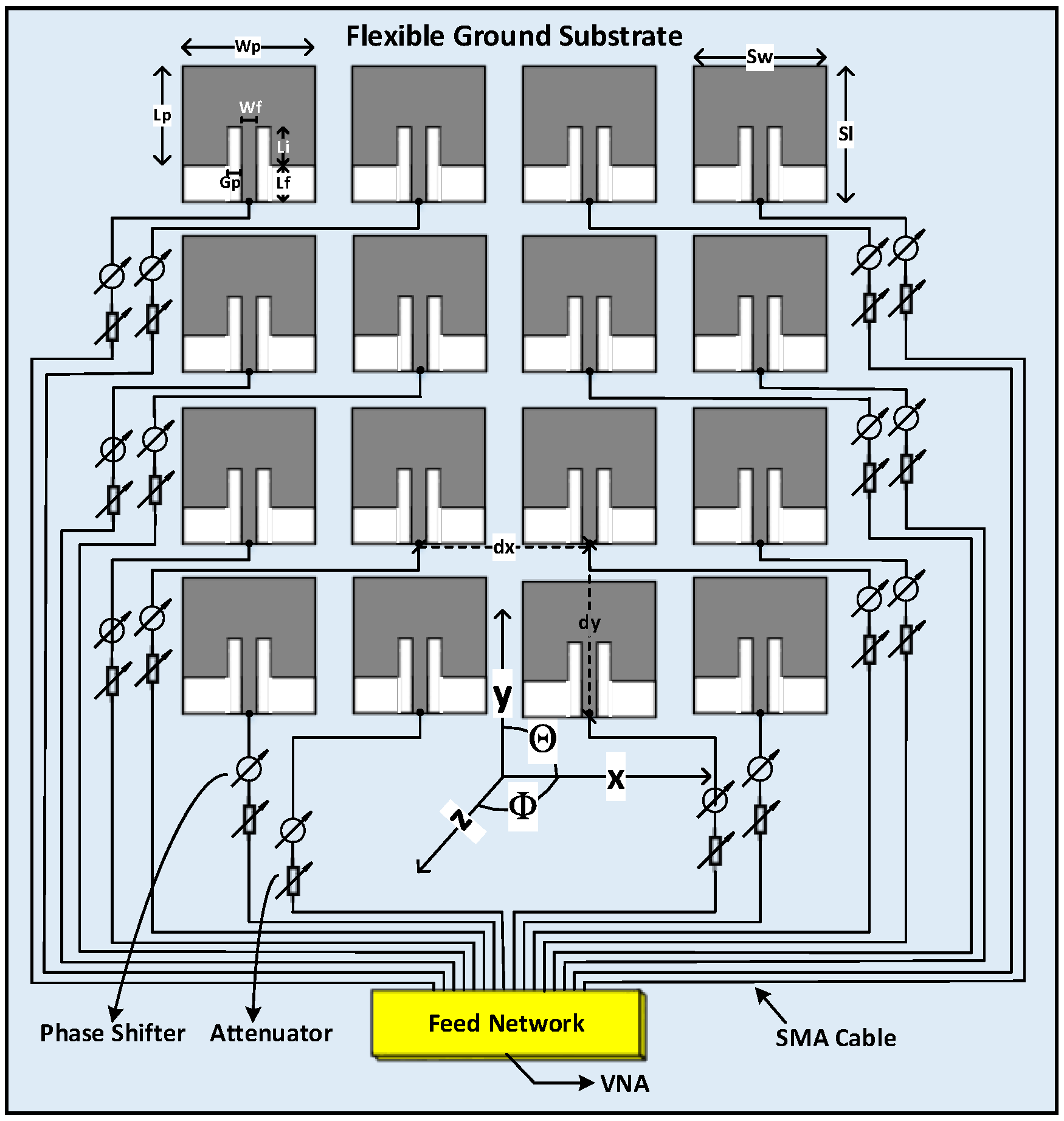
The conformal microstrip array antenna consists of identical radiating elements, and the spacing between adjacent elements is and along the and direction, respectively, with main beam along the z-axis. The design for array is illustrated in Figure 1. The inter-element space between radiating patches is fixed at and all the four prototypes optimized for 28 GHz.
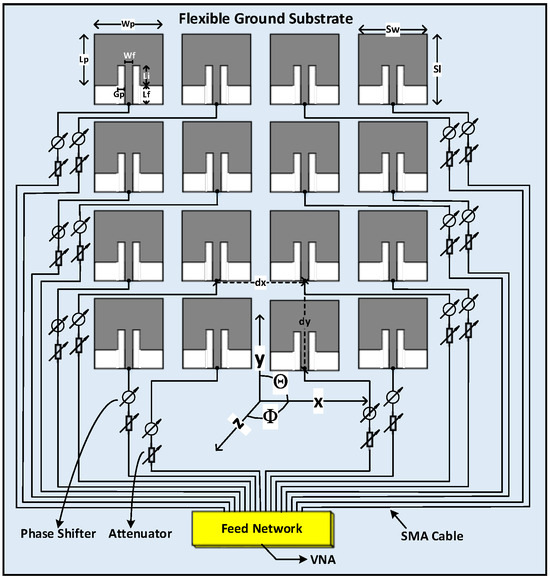
Figure 1.
Design of Conformal Array on flexible ground surface.
The position (spatial coordinates) and orientation (azimuthal and elevation angles) of each antenna element array is determined in CST. Based on the location and normalized angle of the radiating elements of conformal array imported from CST into the algorithm, Equation (1) is used to calculate the array factor for both cylindrical and spherical arrays.
For cylindrical arrays, the expressions for and are given by and , while in spherical arrays, the values of and are given by and . The variables and denote the positions of array elements in array along the axis and axis, respectively. The vector represents the complex weighting function (Amplitude and Phase) required to steer the th element position within the array. represents the wavelength, and ‘’ and ‘’ correspond to the elevation steering angle and azimuth steering angle, respectively. The variable ‘’ represents the propagation constant, while ‘’ and ‘’ denote the progressive phase shifts associated with each radiating element. These phase shifts can be represented as the matrix to be utilized within the algorithm to control the Array Factor as follows:
The Array Pattern, denoted as , is determined by taking the Kronecker product (kron product) of and a matrix . This matrix is compiled by concatenating the individual element pattern vectors. Mathematically, it is given by the following:
Equation (3) represents the array pattern for conformal array antenna with uniform spacing. The resulting radiation pattern of the antenna can be obtained by calculating the magnitude of the array factor and plotting it as a function of the elevation and azimuth angles. In the analysis of the algorithm, the azimuthal angle ‘’ is assumed constant, and the results are obtained for only varying the elevation angle ‘’.
3. Proposed Solution
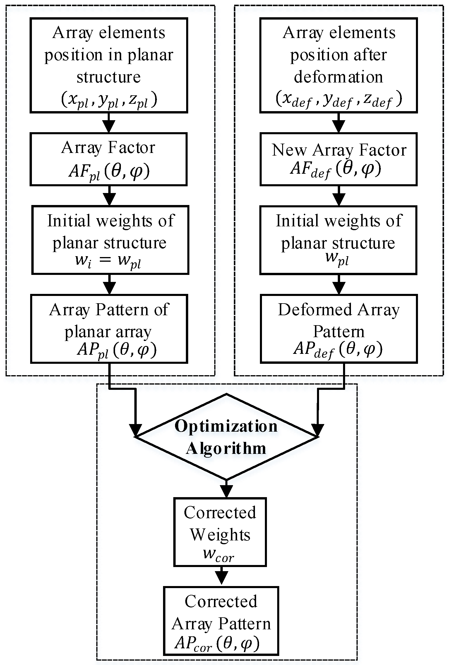
Figure 2 presents a flow chart illustrating the methodology employed for synthesizing the radiation field pattern in the deformed structures of conformal array.
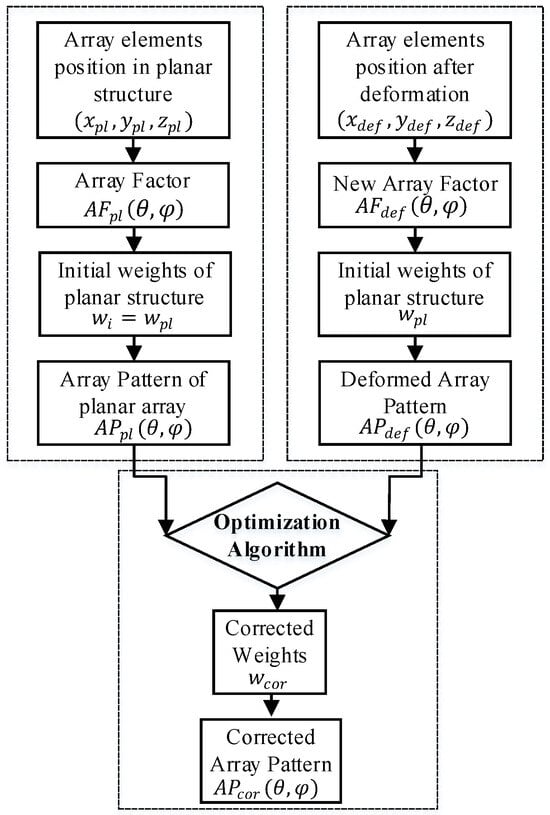
Figure 2.
Proposed compensation technique for the radiation pattern correction.
The electric field pattern is used as the objective function, and the problem is reformulated as a constrained convex optimization problem. The use of constraint convex optimization enables to reach the most optimum performance of the antenna system by finding the best amplitude and phase values for the antenna array. To transform the radiation pattern synthesis problem into a convex optimization problem, the objective function and the constraints are expressed in a form that is agreeable to convex optimization techniques. This involves the use of linear and quadratic programming. The objective of the proposed algorithm is to determine the excitation amplitudes and phases for the antenna elements that produce the desired radiation pattern. The correction of the radiation field pattern synthesis involves adjusting the weights of an existing antenna array to correct for specific deformation from a desired radiation pattern. Convex optimization is used to solve this problem, and several constraint vectors are adopted to ensure that the optimization problem is tractable and can be efficiently solved. The convex optimization itself contains linear constraints that can be formulated to reduce the search space. However, using this approach, the compensated pattern will perform well at the mainlobe peak only and null points but does not care for the rest of the radiation pattern. As a result, mainlobe beamwidth distortion, higher side-lobe level at the edges, and all areas of field away from the constraint points can be distorted. The error performance of this approach, however, tends to improve as more constraints are strategically placed across the radiation pattern, especially at extremal points. Nevertheless, it is worth noting that the maximum number of constraint points has an upper limit. Therefore, convex optimization is introduced within the loops after constraining the pattern in order to allow the corrected/measured field to track the desired field pattern. This closely ensures that the desired null’s location, direction of main beam, and sidelobe levels are accurately achieved.
These constraint vectors are as follows:
- Unit-modulus constraint: The weights of the antenna elements have a magnitude of one over maximum value of mainlobe, as this ensures that the power radiated by the array is conserved. The unit-modulus constraint is formulated as follows:
- Nulling constraint: The field pattern of the antenna array is taken as constrained to have nulls in certain directions, such as to minimize interference from unwanted signals.
Mathematically,
where denotes the Hermitian transpose of the weight vector , * denotes complex conjugation, denotes the steering vector for the specific direction along z-axis, and the equality constraints ensure that the radiation pattern of the antenna array has nulls in the desired directions.
- Constant-envelope constraint: The envelope of the array factor is constant. The constant-envelope constraints ensure that the power radiated by the array is constant over all angles.
- Directional constraint: The radiation pattern such as a specific beamwidth or sidelobe level of the antenna array is taken as constrained along z-axis.
- Hermitian symmetry constraint: The array factor is symmetric about the zero-frequency axis. This ensures that the array does not radiate energy in the opposite direction.
These constraint vectors are imposed, and the optimization problem is formulated as a constraint convex optimization problem, which is efficiently solved using gradient descent numerical optimization technique. Mathematically the technique is described as,
The term constitute the corrected weight excitation, and is given by
where and are the Matrices containing the and constraint vectors at ( position of conformal array in deformed array and planar array, respectively. is the matrix that includes the electric field pattern of each radiating patch of the planar array that has the initial weights . indicates the pseudo inverse and is the convergence factor of the search space ranges from . represent the individual array element pattern in deformed structure and is the electric field pattern of planar array.
4. Results and Discussions
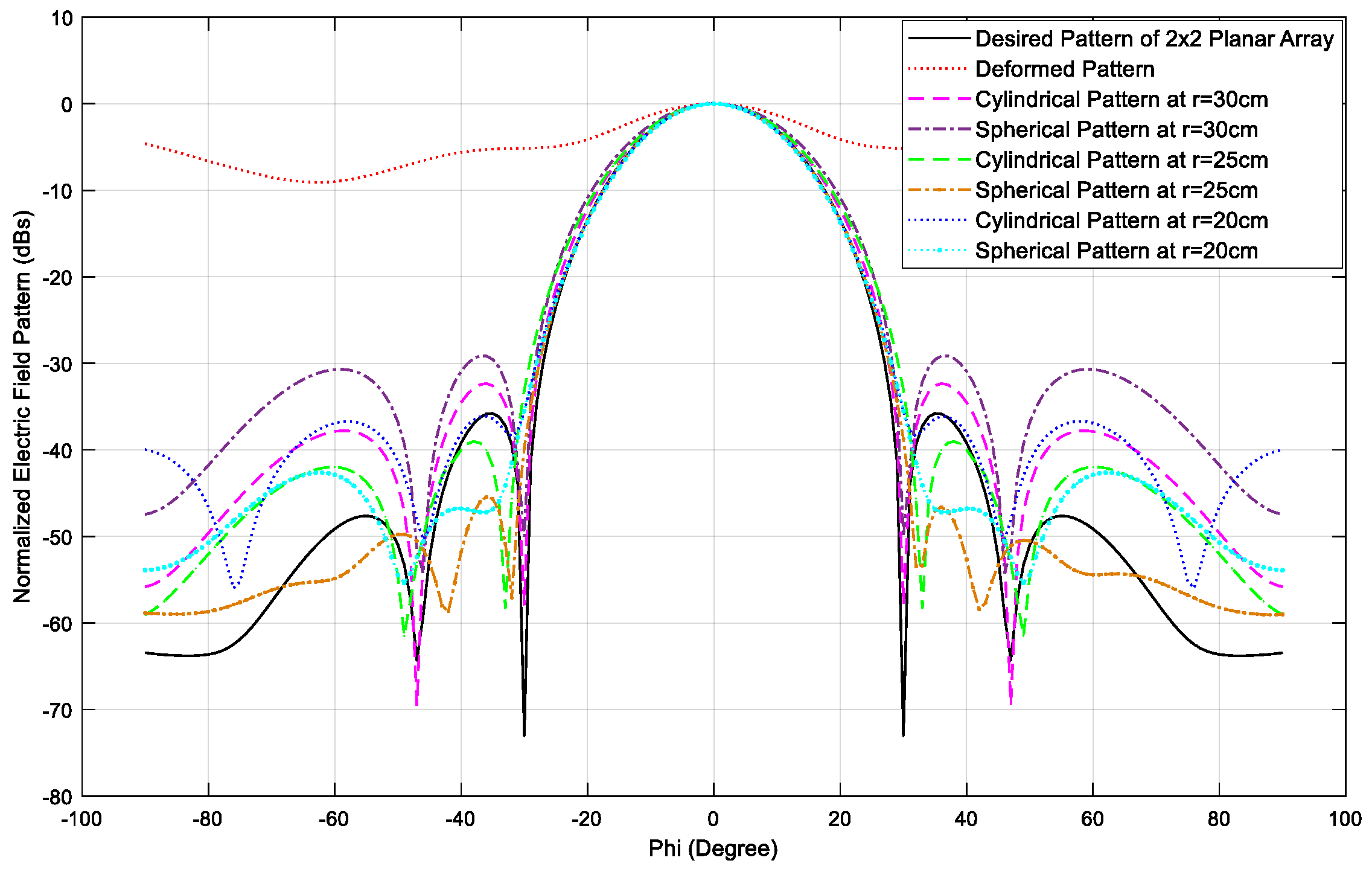
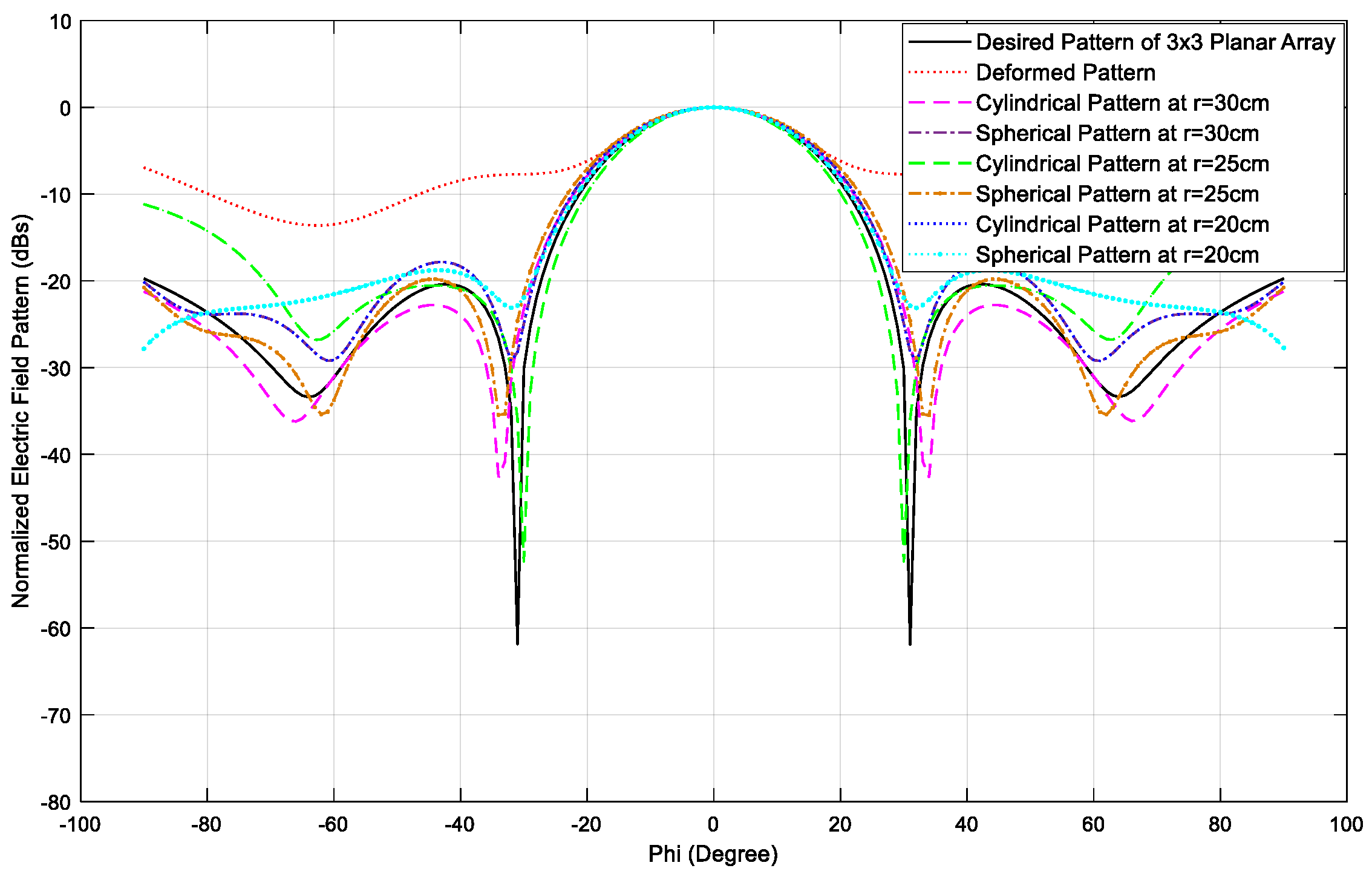
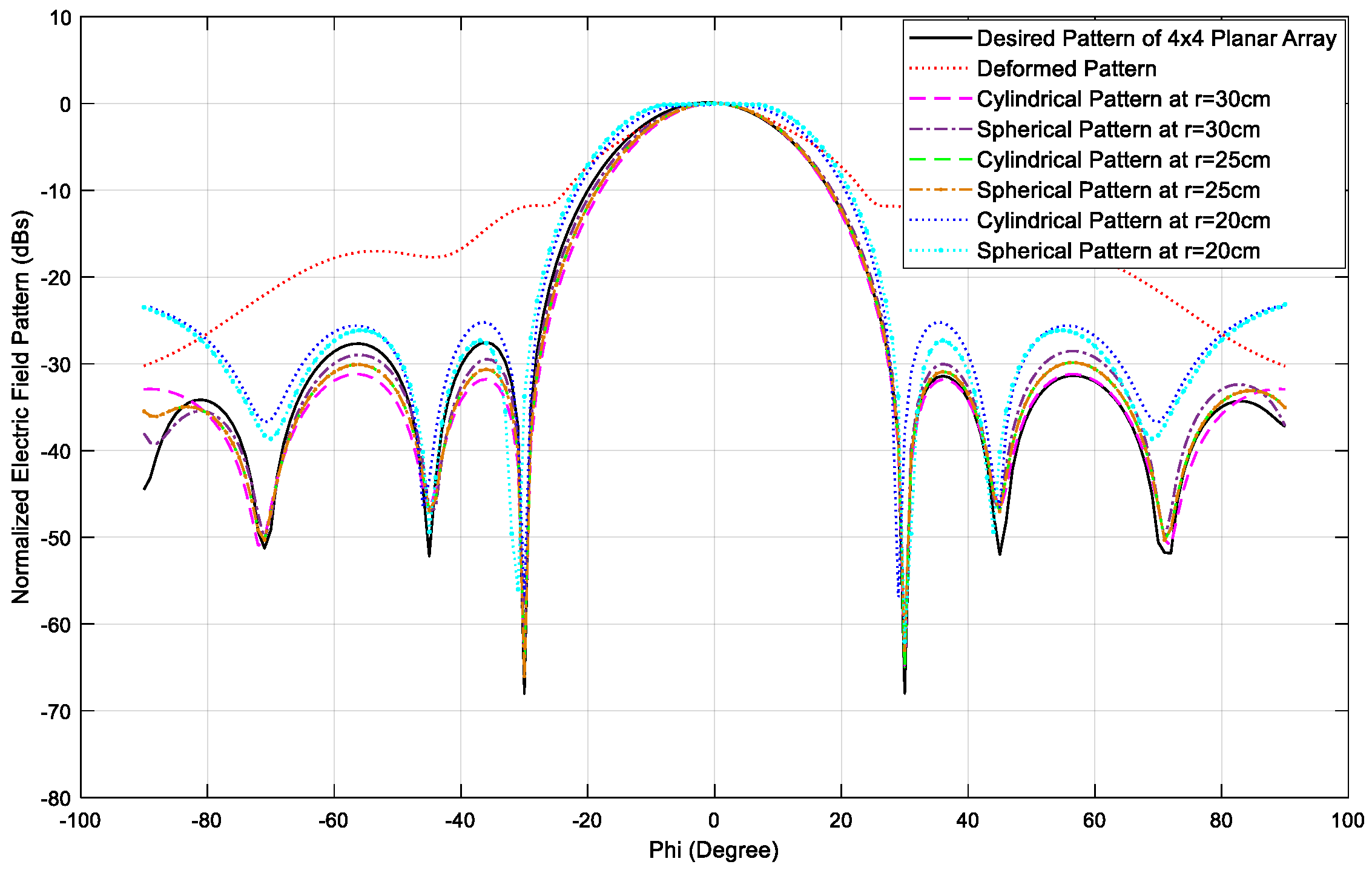
This paper describes a technique for correcting radiation pattern distortions in conformal array antennas caused by surface deformities and mutual coupling between antenna radiating elements. The proposed technique is based on constraint convex optimization, a mathematical approach that involves finding the optimal solution to update the complex weights for the array elements subject to certain constraints that ensure that the corrected radiation pattern meets desired mainlobe direction, beamwidth, null locations, and sidelobe levels. In order to evaluate the performance of an optimization algorithm, the antenna array in planar configuration is deformed to the prescribed spherical and cylindrical configurations with varying radii. The spherical and cylindrical configuration both has three different radiuses: , , and , and the result are shown separately for each case. Four prototypes of , , , and conformal array have been chosen for the analysis. The mainlobe radiation pattern having first nulls at 30° and −30° has been selected and the inter-element spacing between the array elements is taken as 0.5λ. The MATLAB is used for the simulation of optimization algorithm, while CST Studio Suite is used for the verification of its accuracy.
The proposed experimental structure includes a power combiner/splitter feed network, which is coupled to a high gain power amplifier. Following that, RF variable attenuators and voltage-controlled phase shifters are individually attached to this feed network. The phase shifters and attenuators are supplied the amplitude and phase values, which are regulated by variable power supply. A multi-step process for optimizing the performance of the conformal microstrip antenna arrays is initiated. The first step involves obtaining the position vectors of individual array elements in planar as well as deformed structures of conformal array. Then, the computation of the array factor is carried out utilizing the methodology outlined in Section 2 and Section 3 of the study and to obtain the electric field intensity for all the units, preliminary simulations are conducted in CST. The optimization algorithm implemented in MATLAB, outlined by Equations (6) and (8), is then used to evaluate the accurate weight excitations (phase and amplitude values) of the array elements in the deformed conformal array. This optimization algorithm uses the array factor and electric field intensity data obtained in previous steps to calculate the optimal weight excitation values for each antenna unit. After obtaining the calculated weight and phase results, the data are subsequently transmitted back to CST, where the final simulated radiation pattern for the deformed array antenna is validated (Figure 3, Figure 4 and Figure 5).
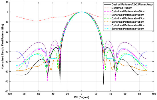
Figure 3.
Results for conformal array.
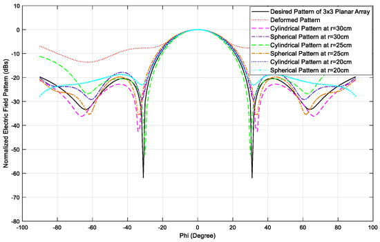
Figure 4.
Results for conformal array.
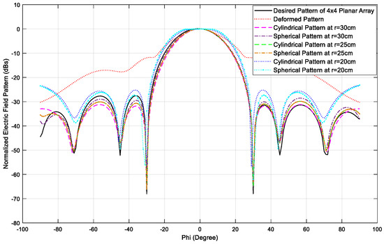
Figure 5.
Results for conformal array.
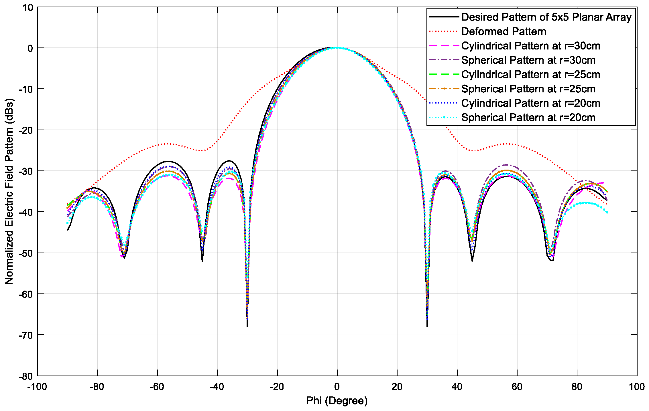
The result reveals that the performance of the optimization algorithm is highly dependent on the physical configuration and number of radiating elements of the antenna array. It is observed that when the array is bent from its planar arrangement to the prearranged spherical and cylindrical configurations, the spacing and orientation of the radiating elements is significantly altered. This results in loss of mainlobe, null positions, and sidelobe levels, and hence a major distortion of the radiation pattern is realized. However, after the deformed arrays have been subjected to the optimization algorithm, the distorted radiation pattern successfully recovers the sidelobes and nulls, and the mainlobe is observed nearly at the same position as that of the planar array. This demonstrates the effectiveness of the optimization algorithm in recovering desired radiation patterns even when the array is not in its ideal geometry. The conformal array performs better when the array is less deformed (with a radius of curvature of 30 cm), enabling the obtained radiation pattern to closely approximate the desired radiation pattern. In contrast, when the array is more deformed (with a radius of curvature of 20 cm), the obtained radiation pattern deviates more from the desired radiation pattern, indicating that the optimization algorithm is less effective in this case. Additionally, increasing the number of elements increases the degrees of freedom available for the optimization algorithm, allowing for a more precise tuning of the radiation pattern. So, the performance of optimization algorithm is best in a 5 × 5 array, followed by the 4 × 4 array, the 3 × 3 array, and the 2 × 2 array, in that order. This is because the 5 × 5 array provides more degrees of freedom for tuning the radiation pattern in desired form. The 5 × 5 array computes appropriate amplitude and phase values for the radiating elements of the array, which restore the radiation pattern in terms of mainlobe reconstruction, null locations, sidelobe levels, up to the deformation of 20 cm in both spherical and cylindrical configurations as shown in Figure 6.
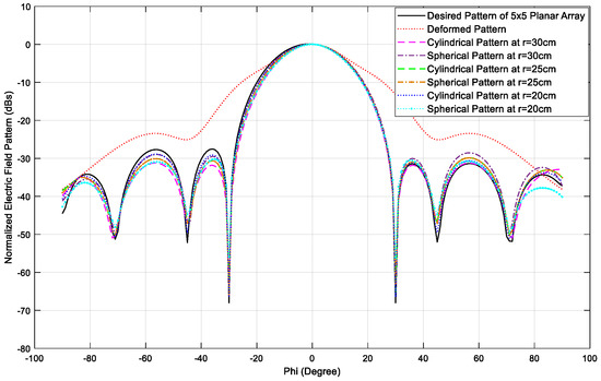
Figure 6.
Results for conformal array.
Table 1 provides a comprehensive overview of techniques utilized in synthesizing radiation patterns for conformal phased arrays. These optimization techniques are purpose-built for specific applications, each carrying its own set of strengths and limitations. Their strengths encompass enhanced computational efficiency and enhanced convergence properties, while their limitations may include increased computational complexity or sensitivity to system parameters.

Table 1.
Comparison of different optimization techniques in conformal phased arrays.
5. Conclusions
In this paper, a model based on constraint convex optimization is proposed for the radiation pattern synthesis in cylindrical and spherical microstrip conformal array antennas. The analysis of square array configurations, which represent a special case where both the rows and columns contain an equal number of radiating patches, is discussed. All the configurations of the conformal square arrays have been precisely designed at the central frequency of . The focus centers on the synthesis of radiation patterns in microstrip conformal square arrays of cylindrical and spherical shapes, while considering the impact of varying the number of elements within the array. The optimization algorithm is modelled to decrease the Euclidean distance between the obtained radiation pattern of the deformed array and the desired radiation pattern of the planar array by calculating the suitable values of amplitude and phase for the array elements. Four prototypes of , , , and microstrip patch array antenna are used as the radiating elements which are deformed from the planar configuration to the prescribed spherical and cylindrical shapes with various radii of curvatures. The results reveal that the performance of optimization algorithm performs better in a 5 × 5 array, followed by 4 × 4 array, 3 × 3 array, and 2 × 2 array; the 5 × 5 array provides more degrees of freedom for tuning the radiation pattern in the desired form. The 5 × 5 array computes appropriate amplitude and phase values for the radiating elements of the array, which restore the radiation pattern in terms of mainlobe reconstruction, nulls locations, sidelobe levels, up to the deformation of in both spherical and cylindrical configurations of conformal array.
Author Contributions
Conceptualization, T.A.K. and M.I.K.; Software, T.A.K.; Methodology, T.A.K.; Validation, M.I.K. and S.A.A.; Formal Analysis, T.A.K. and A.B.; Investigation, T.A.K., A.M.A. and A.A.A.; Writing—Original Draft preparation, T.A.K.; Writing-Review Editing, S.A.A. and A.B.; Supervision, M.I.K.; Visualization: A.B. and S.A.A.; Project Administration: A.B. and S.A.A.; Funding Acquisition: A.B. and S.A.A.; Resources, A.M.A. and A.A.A.; Data Curation: T.A.K. and S.A.A. All authors have read and agreed to the published version of the manuscript.
Funding
This research received no external funding.
Institutional Review Board Statement
Not applicable.
Informed Consent Statement
Not applicable.
Data Availability Statement
Not applicable.
Acknowledgments
The authors extend their appreciation to the Deputyship for Research & Innovation, Ministry of Education in Saudi Arabia for funding this research. (IFKSURC-1-7111).
Conflicts of Interest
The authors declare no conflict of interest.
References
- Hussain, S.; Qu, S.-W.; Sharif, A.B.; Abubakar, H.S.; Wang, X.-H.; Imran, M.A.; Abbasi, Q.H. Current sheet antenna array and 5G: Challenges, recent trends, developments, and future directions. Sensors 2022, 22, 3329. [Google Scholar] [CrossRef]
- Choukiker, M.S.; Kumar, Y. Electronically beam switched conformal microstrip array antenna for 5G applications. Int. J. RF Microw. Comput. -Aided Eng. 2022, 32, e23270. [Google Scholar]
- Nunna, B.A.; Kothapudi, V.K. Design and Analysis of X-Band Conformal Antenna Array for Spaceborne Synthetic Aperture Radar Applications. In Proceedings of the Second International Conference on Computational Electronics for Wireless Communications: ICCWC 2022, Mangalore, India, 9–10 June 2022; Springer Nature: Singapore, 2023. [Google Scholar]
- Tang, B.; Zhou, J.; Tang, B.; Wang, Y.; Kang, L. Adaptive Correction for Radiation Patterns of Deformed Phased Array Antenna. IEEE Access 2019, 8, 5416–5427. [Google Scholar] [CrossRef]
- Khan, T.A.; Khattak, M.I.; Asif, M.; Ahmad, G.; Ibrar, M.; Ali, E.M.; Alibakhshikenari, M.; Dalarsson, M. Radiation pattern synthesis in conformal antenna arrays using modified convex optimization technique. Int. J. RF Microw. Comput. -Aided Eng. 2022, 32, e23393. [Google Scholar] [CrossRef]
- Qin, P.-Y.; Song, L.Z.; Guo, Y.J. Beam steering conformal transmitarray employing ultra-thin triple-layer slot elements. IEEE Trans. Antennas Propag. 2019, 67, 5390–5398. [Google Scholar] [CrossRef]
- Bernhard, J.; Kiely, E.; Washington, G. A smart mechanically actuated two-layer electromagnetically coupled microstrip antenna with variable frequency, bandwidth, and antenna gain. IEEE Trans. Antennas Propag. 2001, 49, 597–601. [Google Scholar] [CrossRef]
- Mazlouman, S.J.; Soleimani, M.; Mahanfar, A.; Menon, C.; Vaughan, R.G. Pattern reconfigurable square ring patch antenna actuated by hemispherical dielectric elastomer. Electron. Lett. 2011, 47, 164–165. [Google Scholar] [CrossRef]
- Mazlouman, S.J.; Mahanfar, A.; Menon, C.; Vaughan, R.G. Square Ring Antenna With Reconfigurable Patch Using Shape Memory Alloy Actuation. IEEE Trans. Antennas Propag. 2012, 60, 5627–5634. [Google Scholar] [CrossRef]
- Mahanfar, A.; Menon, C.; Vaughan, R.G. Smart antennas using electro-active polymers for deformable parasitic elements. Electron. Lett. 2008, 44, 1113–1114. [Google Scholar] [CrossRef]
- Ahmed, Z.A.; Abood, A.H.; Daowd, R.M. Integral Equation Formulation to Radiation Problem from Phased Array Slots Antenna. Al-Qadisiyah J. Pure Sci. 2010, 15, 1–17. [Google Scholar]
- Halleröd, T.; Rylander, T. Shape and excitation optimization for conformal array antennas. Radio Sci. 2008, 43, 1–3. [Google Scholar] [CrossRef]
- Allard, R.; Werner, D.; Werner, P. Radiation pattern synthesis for arrays of conformal antennas mounted on arbitrarily-shaped three-dimensional platforms using genetic algorithms. IEEE Trans. Antennas Propag. 2003, 51, 1054–1062. [Google Scholar] [CrossRef]
- Chaitanya, R.K.; Raju, G.S.N.; Raju, K.V.S.N.; Rao, P.M. Antenna pattern synthesis using the quasi Newton method, firefly and particle swarm optimization techniques. IETE J. Res. 2022, 68, 1148–1156. [Google Scholar] [CrossRef]
- Jin, J.-M.; Lou, Z.; Li, Y.-J.; Riley, N.W.; Riley, D.J. Finite Element Analysis of Complex Antennas and Arrays. IEEE Trans. Antennas Propag. 2008, 56, 2222–2240. [Google Scholar] [CrossRef]
- Ferreira, J.A.; Ares, F. Pattern synthesis of conformal arrays by the simulated annealing technique. Electron. Lett. 1997, 33, 1187–1189. [Google Scholar] [CrossRef]
- Cao, K.; Jin, C.; Zhang, B.; Lv, Q.; Lu, F. Beam Stabilization of Deformed Conformal Array Antenna Based on Physical-Method-Driven Deep Learning. IEEE Trans. Antennas Propag. 2023, 71, 4115–4127. [Google Scholar] [CrossRef]
- Pozar, D. The Active Element Pattern. IEEE Trans. Antennas Propag. 1994, 42, 1176–1178. [Google Scholar] [CrossRef]
- Yang, X.-S.; Qian, H.; Wang, B.-Z.; Xiao, W.S. Radiation Pattern Computation of Pyramidal Conformal Antenna Array with Active-Element Pattern Technique. IEEE Antennas Propag. Mag. 2011, 53, 28–37. [Google Scholar] [CrossRef]
- Huang, X.; Liu, Y.; You, P.; Zhang, M.; Liu, Q.H. Fast Linear Array Synthesis Including Coupling Effects Utilizing Iterative FFT via Least-Squares Active Element Pattern Expansion. IEEE Antennas Wirel. Propag. Lett. 2016, 16, 804–807. [Google Scholar] [CrossRef]
- Liu, Y.; Huang, X.; Xu, K.D.; Song, Z.; Yang, S.; Liu, Q.H. Pattern Synthesis of Unequally Spaced Linear Arrays Including Mutual Coupling Using Iterative FFT via Virtual Active Element Pattern Expansion. IEEE Trans. Antennas Propag. 2017, 65, 3950–3958. [Google Scholar] [CrossRef]
- Mohammed, J.R.; Abdulqader, A.J.; Thaher, R.H. Array Pattern Recovery Under Amplitude Excitation Errors Using Clustered Elements. Prog. Electromagn. Res. M 2020, 98, 183–192. [Google Scholar] [CrossRef]
- Hu, W.; Wang, X.; Li, Y.; Xiao, S. Synthesis of Conformal Arrays With Matched Dual-Polarized Patterns. IEEE Antennas Wirel. Propag. Lett. 2015, 15, 1341–1344. [Google Scholar] [CrossRef]
- Lin, H.S.; Cheng, Y.J.; Fan, Y. Synthesis of Difference Patterns for 3-D Conformal Beam-Scanning Arrays With Asymmetric Radiation Aperture. IEEE Trans. Antennas Propag. 2022, 70, 8040–8050. [Google Scholar] [CrossRef]
- Tsui, K.M.; Chan, S.C. Pattern Synthesis of Narrowband Conformal Arrays Using Iterative Second-Order Cone Programming. IEEE Trans. Antennas Propag. 2010, 58, 1959–1970. [Google Scholar] [CrossRef]
- Chiba, I.; Hariu, K.; Sato, S.; Mano, S. A projection method providing low sidelobe pattern in conformal array antennas. In Proceedings of the Digest on Antennas and Propagation Society International Symposium, San Jose, CA, USA, 26–30 June 1989. [Google Scholar]
- D’Elia, G.; Romito, G.; Bucci, O.M. Power synthesis of conformal arrays by a generalised projection method. IEE Proc.-Microw. Antennas Propag. 1995, 142, 467–471. [Google Scholar]
- Patwari, A.; Reddy, G. A Conceptual Framework for the Use of Minimum Redundancy Linear Arrays and Flexible Arrays in Future Smartphones. Int. J. Antennas Propag. 2018, 2018, 9629837. [Google Scholar] [CrossRef]
- Braaten, B.D.; Roy, S.; Irfanullah, I.; Nariyal, S.; Anagnostou, D.E. Phase-Compensated Conformal Antennas for Changing Spherical Surfaces. IEEE Trans. Antennas Propag. 2014, 62, 1880–1887. [Google Scholar] [CrossRef]
- Ullah, I.; Munsif, H.; Razzaq, S.; Najam, A.I. Cylindrical phased array with adaptive nulling using eigen-correlation technique. Int. J. RF Microw. Comput. -Aided Eng. 2022, 32, e22969. [Google Scholar] [CrossRef]
- Rammal, H.; Olleik, C.; Sabbah, K.; Rammal, M.; Vaudon1, P. Synthesis of phased cylindrical arc antenna arrays. Int. J. Antennas Propag. 2009, 2009, 691625. [Google Scholar] [CrossRef]
- Alinezhad, P.; Seydnejad, S.R. Broadband adaptive beamforming of conformal arrays for wireless communications based on generalized sidelobe canceller. Wirel. Pers. Commun. 2017, 96, 1131–1143. [Google Scholar] [CrossRef]
- Li, W.-T.; Hei, Y.-Q.; Shi, X.-W. Pattern synthesis of conformal arrays by a modified particle swarm optimization. Prog. Electromagn. Res. 2011, 117, 237–252. [Google Scholar] [CrossRef]
- Saxena, P.; Kothari1, A. Optimal pattern synthesis of linear antenna array using grey wolf optimization algorithm. Int. J. Antennas Propag. 2016, 2016, 1205970. [Google Scholar] [CrossRef]
- Keizer, W.P. Element failure correction for a large monopulse phased array antenna with active amplitude weighting. IEEE Trans. Antennas Propag. 2007, 55, 2211–2218. [Google Scholar] [CrossRef]
- Aksoy, E.; Afacan, E. Planar antenna pattern nulling using differential evolution algorithm. AEU -Int. J. Electron. Commun. 2009, 63, 116–122. [Google Scholar] [CrossRef]
Disclaimer/Publisher’s Note: The statements, opinions and data contained in all publications are solely those of the individual author(s) and contributor(s) and not of MDPI and/or the editor(s). MDPI and/or the editor(s) disclaim responsibility for any injury to people or property resulting from any ideas, methods, instructions or products referred to in the content. |
© 2023 by the authors. Licensee MDPI, Basel, Switzerland. This article is an open access article distributed under the terms and conditions of the Creative Commons Attribution (CC BY) license (https://creativecommons.org/licenses/by/4.0/).