Abstract
Smooth surface blasting control technology is aimed at blasting the rock body until it is left with a smooth surface and to protect it from damage; the current air spaced axial uncoupled charge and air spaced radial uncoupled continuous charge are effective charging structures for smooth surface blasting. Reserved air spacing can effectively reduce the blast wave and the peak pressure of the explosive gas, improving the quasi-static pressure of the explosive gas under the action of rock surface blasting with fracture seam quality. In order to ensure the effect of surface blasting, small-diameter light surface holes are more often used; with the development of drilling machinery, the use of large-diameter light blast holes with an oversized uncoupled coefficient of loading structure effectively improves the efficiency of the construction and at the same time achieves better blasting results. However, according to the bursting assumption of obtaining the theory of light surface blasting in the application of large uncoupling coefficient loading, light surface blasting has certain limitations. In this regard, the bursting theory explores the air spacing uncoupling charge in line with the multi-faceted exponential expansion of the critical uncoupling coefficient and is in accordance with the following: the requirements of light surface blasting and the field loading structure; the derivation of the quasi-static pressure on the wall of the gunhole under the action of large uncoupling, uncoupling coefficient, and the parameters of the spacing between the gunholes; the establishment of the axial uncoupling coefficient and the radial uncoupling coefficient-equivalent relationship between the uncoupling coefficient and the theoretical relationship between the selection of the spacing between the holes; the uncoupling coefficient and the selection of the theoretical relationship between the spacing between the holes. This study reveals the mechanism by which different parameters of surface blasting can achieve good results in engineering practices. A slope in Guizhou is an example of sample calculations and the application of two different charging structures applied to field loading, which have achieved good surface blasting results.
1. Introduction
Smooth blasting is one of the commonly adopted methods of controlled blasting. The objective of this technique is to cause as little damage to the surrounding rock mass as possible while leaving a smooth surface of the unexcavated rock face. Residual half-hole walls are an important indicator of successful smooth blasting [1,2,3,4]. The currently adopted effective charge structures for smooth blasting are the air-spaced axial uncoupled charge and air-spaced radial uncoupled continuous charge. Air has high compressibility and wave impedance value relative to the rock; therefore, the blast wave generated by the explosion first compresses air in the gap, producing an air shock wave, which then impacts the wall of the drilled holes. The air-spaced charge serves three purposes: (1) Air-spaced charge has a buffering effect on the blast stress wave, which reduces the peak blast stress and improves the rock breaking effect. (2) Air-spaced charge increases the time duration of the explosive stress wave. This, on the one hand, reduces the impact pressure, which in turn reduces the energy of the drilled hole wall fragmentation. On the other hand, the cushioning of the air also increases the action time of the stress wave. (3) It increases the impulse of the stress wave acting on the rock. This allows uniform distribution of the specific impulse along the shell, which can effectively improve the quality of the crushing blocks and avoid the formation of large blocks [5,6,7,8,9,10,11]. Chen et al. [12] stated that adopting a larger axial uncoupling coefficient for an axial air bedding charge in a blast hole affects the magnitude of the peak pressure acting on the blast wall and the loading time duration of the quasi-static pressure of the explosive gas. By increasing the axial uncoupling coefficient, the peak pressure decreases, whereas the positive pressure action time is prolonged.
To achieve the desired effect of smooth blasting, three conditions must be satisfied when defining the structural parameters of the air-spaced charge:
(1) To ensure that no compressive damage occurs to the blast hole wall, it is necessary that the initial peak radial stress acting on the wall is lower than the compressive strength of the surrounding rock.
(2) To ensure the formation of radial cracks in the blast hole wall, the initial peak tangential stress acting on the blast hole wall must be higher than the tensile strength of the surrounding rock.
(3) To ensure the formation of inter-hole penetration cracks, the spacing between the holes must be smaller than the length of the burst cracks.
Du et al. [13] theoretically calculated the axial uncoupling coefficient, which plays a decisive role in establishing the structural parameters of the small aperture air cushion charge. Similarly, Xu and Zong [14] conducted a theoretical analysis and developed a method to determine the structural parameters of the axially uncoupled charge of the air and water cushions for small-aperture smooth blasting. Ling [15] established a fracture mechanics model for smooth blasting and pre-cracking blasting with a blast hole diameter of 42 mm and a charge diameter of 25 mm. They analyzed the role of stress waves and quasi-static pressure of explosion-generated gas in the blast rupture process. Monjezi and Dehghani [16] studied the artificial neural network (ANN) technique to determine the near-optimum blasting pattern. This method is applied in Gol-E-Gohar iron mine. Kumar et al. [17] studied minimizing vibration while drilling and obtaining the optimal operating condition to enhance drill performance. Based on the deep neural network research, analysis of the relationship between blasting parameters and rock fragmentation was established by Bai et al. [18], and sensitivity analysis was performed on blasting parameters. Monjezi et al. [19] provided a powerful technique to optimize the blast parameters in open pit blasting operations based on the genetic algorithm. The understanding of the relationship between cracked-zone radii and the dominant frequency of vibrations during tunnel blasting was studied by Liu et al. [20] using theoretical, numerical, and in situ measurement approaches. The rock fragmentation induced by blasting using a decoupled charge is investigated by Li et al. [21] combining finite element modelling and image processing. The results showed that rock fragmentation became finer, and the fragmentation size distribution range becomes narrower with the decrease in the decoupling ratio. Qin et al. [22] found that for the Liuzhi-Anlong highway tunnel blasting construction, light surface blasting effects are poor, and by using a numerical simulation to optimize the reasonable blasting parameters, they found that the radial uncoupling coefficient of 1.25 and the distance between the holes for the site of the 55 cm blasting application produced good results. Tian et al. [23], through the test to explore the effect of uncoupled charges on the concrete blasting effect, produced results that show that the optimal uncoupling coefficient is 1.85 when the air is not in a coupled charge; polystyrene (EPS) foam is not coupled to the optimal uncoupling coefficient of 1.65 when the charge is not coupled.
To facilitate the loading, the diameter of the explosive charge is generally kept smaller than the diameter of the blast hole. To avoid excessive crushing of the hole wall, the axial and radial uncoupled charging are used widely in the smooth surface blasting construction process. Smooth blasting operations in roadways and tunnels are limited by the size of the excavation section and the direction of excavation. To maintain the effectiveness of light blasting, air-legged rock drills are still used more often in the open terrace or slope light blasting with a drill hole diameter of 42 mm and charge diameter of 25 mm or 12.5 mm [15]. However, with the advancement of drilling machinery such as crawler hydraulic submersible drills, a larger diameter (90–140 mm) is often adopted for smooth blasting holes in open slopes to accelerate the construction progress and mechanization level, while still using an explosive charge diameter of 32 mm or 35 mm [15,24]. Chen et al. [25] used large-diameter deep-hole blasting for ore chipping in mining, according to the actual ability of the engineering site to use the uncoupling coefficient of 2.36 of the charging structure and achieve good application results. Using a charge with a larger uncoupling factor can increase the quasi-static effect of explosive gas, while reducing the damage incurred to the blast hole. The classical theory of smooth blasting considering large uncoupling charging has not been well analyzed and solved for the blast parameters of large uncoupling charging [26,27,28,29,30,31,32,33].
The present study aims to determine the axial and radial uncoupled charge coefficients, the force acting on the blast hole wall, and the distance between adjacent blast holes under the action of an uncoupled charge in order to effectively improve the utilization rate of explosive energy and improve the blasting effect. From the blasting theory, axial and radial critical uncoupling coefficients are solved according to the actual detonation expansion law. The calculation methods for estimating quasi-static pressure, uncoupling coefficient, and blast hole spacing under the action of a large uncoupling coefficient charge were explored based on the requirements of the structure of smooth surface blasting and field charging. A slope in Guizhou was taken as the research subject for the present study. The proposed light surface blasting method was applied in the field, and satisfactory light surface blasting effects were obtained.
2. Classical Theory of Uncoupled Charge Smooth Blasting
2.1. Impact Pressure on the Blast Hole Wall with a Radially Uncoupled Continuous Charge
In the case of uncoupled charges, the blast wave first compresses the air present in the gap, producing an air shock wave. This air shock wave impacts the blast hole wall. The following assumptions are considered for the study:
(1) Absence of air in the interstices;
(2) Blast products are generated in the gap, which follows the law of PVn = constant (n = 3), where P is pressure and V is volume.
(3) The initial pressure at expansion is calculated as the average impact pressure.
Based to the above assumptions, the initial pressure acting on the blast hole wall is calculated as follows:
The average impact pressure Pc of the explosion products is expressed as
where ρ0 is blast product density, and D1 is blasting velocity.
The pressure before the by-products of the explosion hits the wall of the shell, i.e., the incident pressure Pf is
According to the research of K.K. Andreyev and A.Φ. Belyoyev (Xu and Zong [14]), the pressure amplifies by 8–11 times when the gaseous by-products impact the blast hole wall. Therefore, under the condition of an uncoupled charge, the impact pressure P2 acting on the blast hole wall is
where is the density of explosives; D1 is the detonation velocity of the explosive; Vc is the volume of by-product gases before expansion; Vb is volume of the expanded blast by-products in the blast hole; dc is charge diameter; db is blast hole diameter.
2.2. Smooth Blasting Theory
In order to achieve better smooth blasting effects, the impact pressure acting on the wall of the hole should not be greater than the compressive strength of the rock under the action of the explosive load. Radial uncoupled continuous charge and axial uncoupled charge mode are used to reduce the damage to the blast wall surface, as discussed below:
(1) Radial uncoupled continuous charge: Under the condition of this uncoupled charging, the impact pressure P2 acting on the blast wall can be derived using Equation (3).
(2) Axial uncoupled charge: In this case, the explosive properties are not changed, and blasting products are distributed homogenously. In accordance with this assumption, the density ρ of blasting products in the air column is
The impact pressure P3 acting on the blast hole wall under this condition can be calculated as
where la is the length of the air column; lc is the charge length. If the length of mud in the hole is neglected, la + lc = lb, wherein lb is the length of the borehole. Assuming that the impact pressure P3 is not greater than the compressive strength of the rock, the charge coefficient lL can be obtained from Equation (5):
where Sc is uniaxial compressive strength; Kb is rock amplification factor of rock under dynamic loading.
The above equation is derived based on the three assumptions stated in Section 2.1. The derived results can only be correct under the condition of PVK = constant (n = 3). However, due to the large uncoupling coefficient in large diameter drilled holes, the air gap is large, and the expansion of the blasting products cannot strictly comply with the conditions of PVK = constant (K = 3). Therefore, based on the blast theory, the large uncoupling coefficients should be induced according to PVK = constant (K = 3) (n is arbitrary number).
3. Critical Uncoupling Coefficient of Large Diameter Drilled Holes
3.1. Blasting Critical Uncoupling Coefficient
In the condition of high blasting pressure, the results of Equations (1)–(6) for the blast products can meet the assumption that PV3 = constant. However, as the gas expands, the pressure decreases, and the equation of state of blasting gas follows the law of PVK = constant (K = 1.2–1.3). There is a critical pressure between blast products for PV3 = constant and PVK = constant (K=1.2–1.3). The critical pressure PK is
where E is the amount of energy contained in a unit mass explosive; Pc is blast pressure. The value of PK is approximately calculated to be 200 MPa.
When the gas pressure is greater than the critical pressure, the results obtained from Equation (6) are correct. When the expansion reaches the critical pressure, the volume of gas VK should be
where Vc is volume of charge. Three conditions are discussed as below.
(1) For radial uncoupled continuous charge, lb = lc; when the blasting gas expands to fill the entire hole, the volume of gas VK follows:
For this condition, the critical radial uncoupling coefficient Kdmax is
(2) When radially coupled axially uncoupled charges are used, the gas expands to fill the entire blast hole, and the volume of gas VK follows:
Herein, the critical axial uncoupling coefficient Klmax is
(3) For a radially and axially uncoupled charge, the gas expands to fill the entire blast hole, and the volume of gas VK follows:
Herein, the uncoupling coefficient Kdlmax is found to be
The rock emulsion explosive is taken as a second example. The density of this explosive is 1.24 g/cm3 with a blasting velocity D1 of 4200 m/s. According to Equations (10), (12) and (14), the values of Kdlmax and Kdmax for this explosive are smaller than 1.54, and values of Klmax are smaller than 2.4. It can be seen that when the gas pressure is greater than the critical pressure and the gas expands to fill the entire blast hole, the radial uncoupling coefficient and the radial axial uncoupling coefficient becomes equal, although they are smaller than that of the radial coupling axial uncoupling charge. When the axial uncoupling coefficient is greater than the critical uncoupling coefficient, the blast hole void interval becomes large, and the blasting gas expands following the ideal gas equation of state. For the large uncoupling coefficient charge, the dynamic impact of the explosion products will continue to weaken, while the quasi-static pressure of the blasting gas enhances this phenomenon further. As a result, when the uncoupling factor exceeds the critical uncoupling factor, the classical theory for impact pressure generated by uncoupled charge in blast hole will no longer apply, and the smooth blasting parameters need to be revised.
3.2. Radial Axial Uncoupling Equivalence Assumption
Because the diameter of the drill rig is not consistent with that of the explosive charge, smooth blasting has an axial uncoupled charge and radial uncoupled charge. In order to study the impact pressure acting on the blast hole wall under the combined action of the two and ensure the generation of a smooth wall, the axial radial uncoupled charge is taken as an equivalent to the radial uncoupled continuous charge. The equivalence process can be divided into two types: one is based on the shape of the hole being unchanged, and the other is based the shape of the explosive being unchanged, while the volume of the blast hole is the same. The above equivalence satisfies the following assumptions:
(1) The charge quality of blasting hole is certain, and the equivalent process does not consider the critical diameter value of explosive detonation.
(2) The explosive density during the charging process is uniform and constant.
When the radial and axial uncoupled charge is equivalent to the radial uncoupled continuous charge, the equivalent charge diameter may be less than the critical diameter of the explosive detonation. In reality, the explosive diameter is greater than the critical diameter, and assumption (1) can be met. As only the charge structure of the blasting hole is changed, and the size and composition of the explosives used in each hole remain unchanged, assumption (2) basically holds.
Considering that the shape of the blast hole remains the same and the explosives are equivalent, the cross-sectional view of an equivalent blast hole for the axial uncoupled charge is shown in Figure 1.
Figure 1.
Cross-sectional view of equivalent uncoupled charge in the blast hole.
The radially and axially uncoupled charge is equivalent to a radial uncoupled continuous charge, wherein the explosive mass is equal, and the explosive density is constant. This leads to
The equivalent diameter for a radially uncoupled continuous charge is obtained from Equation (15) as
Substituting Equation (16) in Equation (3), the impact pressure P3 acting on the blast hole wall for the case of an axially and radially uncoupled charge is obtained as follows:
The radial uncoupling coefficient Kd (Kd = db/dc and axial uncoupling coefficient K1 (K1 = (la + lc)/lc) can be obtained by substituting into Equation (17):
Considering that the shape of the explosive remains the same and the volume of the blast hole is equivalent, the cross-sectional view of an equivalent blast hole for the radially and axially uncoupled charge is shown in Figure 2.
Figure 2.
Cross-sectional view of an equivalent blast hole for a radially and axially uncoupled charge.
For a fixed blast hole, the radial axial uncoupled charge is equivalent to the radial uncoupled continuous charge, as shown in Figure 2. The equivalent process of blast hole volume remains unchanged. This leads to
The diameter of an equivalent blast hole for a radially uncoupled continuous charge is obtained from Equation (4) as
Substituting Equation (20) in Equation (3), the impact pressure acting on the wall of the axially and radially uncoupled charge is obtained from Equation (18). Equivalent uncoupling coefficient is obtained by combining Equations (16) and (20) as
For light surface blasting, especially for an open terrace and road rift valley, a large diameter submerged hole drill (diameter Φ80–100) is generally used. To avoid over-crushing of the loaded section, a small diameter charge (diameter Φ32) is commonly used. These will have large radial and radial–axial uncoupling coefficients, respectively. For instance, a blast hole with diameter of 90 mm is selected, and two charges with diameter of 32 mm are bundled together. The equivalent diameter is approximated as 45 mm, the radial uncoupling coefficient is 2, and the axial uncoupling coefficient is taken as 3. The rock strength is selected as 80 MPa, and No. 2 rock emulsion explosive is used. According to Equation (6), the charge coefficient lL is greater than 1, which contradicts the considered case of a charge coefficient less than 1. The impact pressure P2 acting on the wall of the blasting hole is less than the dynamic compressive strength of the rock, and P3 is even less than the compressive strength of the rock.
4. Calculation of Wall Pressure and Uncoupling Factor for Light Surface Blasting Holes with Very Large Uncoupling Factor
4.1. Impact Pressure Generated by Shock Wave Based on Large Uncoupling Coefficient
In the case of a large axial uncoupling coefficient, a shock wave is first generated in the air gap, and then the shock wave impinges on the hole wall to generate impact pressure. The propagation velocity Da of the air shock wave can be calculated according to the following equation (Zong and Meng [34]):
where umax is the maximum velocity of diffusion of the burst products; r is distance from the center of the charge; rc is charge radius.
The maximum diffusion velocity of the burst products can be calculated according to the following equation:
where k is the average adiabatic index of air in the air gap (k = 1.17–1.25); Q is explosion energy of explosives.
The incident pressure of the air shock wave when it collides with the blast hole wall is
where ρa is the air density.
The impact pressure P4 when the shock wave hits the blast hole wall is calculated as
where N is the pressure increase factor, which can be referred to as shown in Figure 3.
Figure 3.
Relationship between the pressure increase factor N and air shock wave Pλ.
When a radially uncoupled continuous charge is used, the relationship between the pressure acting on the blast hole wall and the uncoupling factor is
When a radially and axially uncoupled continuous charge is used, the relationship between the blast hole wall pressure and uncoupling coefficient is
4.2. Impact Pressure Generated by Gas Expansion Based on Large Uncoupling Coefficient
The radial axial uncoupling coefficient is greater than the critical uncoupling coefficient under smooth blasting. Thus, assumption 2 presented in Section 2.1 should be modified. When the critical gas volume is less than the volume of the blasting hole, the gas will continue to expand, obeying the gas state equation PVK = constant (K = 1.2–1.3). The static pressure when the product of the blast fills the blast hole should be
For a radial uncoupled continuous charge, substituting Vc = πdc2Lb/4, Vb = πdb2Lb/4, Kd = db/dc in Equation (28) produces
Equation (16) or Equation (20), for the equivalent charge diameter, radial uncoupling coefficient Kd, and axial uncoupling coefficient K1(K1 = (la + lc)/lc) presented in Section 3.2, are substituted into Equation (28), and the quasi-static pressure acting on the blast hole wall for the axial and radial uncoupling charge is obtained as
Depending on the blast gas pressure for the static condition, the stress field formed in the rock around the hole can be subjected to uniform internal pressure of the thick-walled cylinder theory solution, with radial and tangential stress of
where σr(θ) is the radial and tangential stress at a point in the rock; rb is the radius of the blast hole; r is the radial distance from the blast point. The equation shows that the magnitude of radial stress is the same as the tangential stress; however, their directions are opposite. The absolute value of pressure generated in the blast hole wall is pb.
4.3. Calculation of Large Uncoupling Coefficient
4.3.1. The Initial Peak Radial Stress in the Surrounding Rock of the Blast Hole Lower Than the Compressive Strength of the Rock
- (1)
- The axial uncoupling factor based on the impact pressure generated by a shock wave:
For the radial and axial uncoupled charge, there are no evident cracks on blast hole walls. To ensure that no compressive damage occurs in the surrounding rock of the blast hole, especially in the loaded section, it is necessary that the peak initial radial stress acting on the rock is lower than its compressive strength. Since the values of the uncoupling coefficient, K1, and Kd are greater than 1, P4″ < P4′. Therefore, Equation (26) for large uncoupling factor is modified to satisfy a smaller value as
- (2)
- The axial uncoupling factor based on impact pressure generated by gas expansion:
Similarly, for the gas expansion pressure on the blast hole wall, since the uncoupling factors, K1 and Kd, are greater than 1, Pb3 < Pb2. This implied that the charging section can be assumed to be a radially uncoupled continuous charge. Bringing Equation (30) into the transformation solution yields
4.3.2. The Peak Initial Tangential Stress in the Surrounding Rock of the Blast Hole Higher Than the Tensile Strength of the Rock
- (1)
- The axial uncoupling factor based on the impact pressure generated by a shock wave:
To ensure formation of radial cracks in the surrounding rock of the blast hole, the peak initial tangential tensile stress acting on the rock should be higher than the tensile strength of the rock. Due to the guiding effect between adjacent blast holes, the concentration of tensile stress will occur in the direction of the blast hole centerline. This effect would be the strongest at the blast hole wall, thus increasing the initial tangential tensile stress value in the surrounding rock of the blast hole. Based on Kθσθ > St, since the values of the uncoupling coefficients (shown in Figure 4), K1 and Kd, are greater than 1, P4″ < P4′. Therefore, Equation (27) is brought into the transformation to find
Figure 4.
Tensile stress concentration coefficient curve (Gao et al. [35]).
- (2)
- The axial uncoupling factor based on the impact pressure generated by gas expansion:
Similarly, for the gas expansion pressure acting on the blast hole wall, since the values of the uncoupling coefficients, K1 and Kd, are greater than 1, Pb2 < Pb1. This indicates that the charge section can be assumed as a radial uncoupled continuous charge. The quasi-static pressure in the axial air-spaced section is less than that in the charge section; therefore, Pb1 > Pb2 > St. As long as the quasi-static pressure in the axial air spacing section is greater than the tensile strength of the rock, it can meet the conditions. Thus, the uncoupling coefficient can be calculated as
4.3.3. Hole Spacing to Be Less Than the Length of the Burst Fracture
- (1)
- Blasting hole spacing:
In accordance with the theory of the joined action of stress waves and explosive gas, blast hole spacing can be determined as
The required blast hole spacing is
- (2)
- Inter-hole burst crack propagation:
During light surface blasting in the rock, due to the presence of adjacent blast holes, the stress state near the blast hole wall is changed, resulting in the concentration of tensile stress in the direction of the blast hole center line. The cracks are generated and developed by the impact of gas expansion on the blast hole wall. When the strength factor in the crack tip region is less than the fracture toughness value of the rock, the crack extension will stop. Assuming that the depth of gas wedging into the rock is equal to the crack extension length and considering gas leakage and energy consumption, the pressure change on the blast hole wall will be
where l is crack extension length (m); α is stress decay index.
The fracture toughness of a rock can be defined as its ability to stop the destabilizing expansion of a crack. It is independent of the shape and size of the fracture and external forces. It is only related to the rock composition, which is a characteristic of the rock itself. Two cases can be considered as follows: for K1 > KIC, the crack is destabilizing, expanding, and brittle; for K1 < KIC, the stress intensity factor of the fracture cut-off is (Zhang et al. [36])
According to the Griffith strength theory, the fracture toughness of rock under plane strain conditions is
where E is the modulus of elasticity (kg/cm2); T is unit surface energy; v is Poisson’s ratio.
According to Griffith’s strength theory, fracture toughness KIC under plane strain conditions is
Under quasi-static gas action, the tension on the fracture surface can be considered to be equal to the gas pressure in the blast hole. Because of the guiding effect between adjacent blasting holes, the phenomenon of tensile stress concentration is generated in the radial direction of the blasting hole. By making full use of energy, it can be concluded from Equations (16) and (17) that
That is
Substituting Equation (15) into (17) gives
Substitution of Equation (5) into Equation (19) gives
For adjacent blast holes, the value of the blast hole spacing is equal to the blast crack in the rock extension crack length. For a single shell hole, the crack length generated by the blast load is equal to half of the blast hole spacing:
Therefore, all three requirements must be met when determining the axial uncoupling factor of the air cushion blast charge. The radial uncoupling factor of the charge structure is taken as the maximum value between Equations (32) and (33). The values of axial uncoupling factor and blast hole spacing are determined using Equations (34), (35) and (48).
5. Calculation Examples and Engineering Applications
5.1. Physical and Mechanical Testing of Rocks
To ensure the practical application of the proposed smooth blasting method, it is applied to the earth work project of Qianxi to Dafang Expressway, Guizhou, China. The volume of excavation reaches 2.88 million m3. The rocky section accounts for more than 80% of the entire excavation in the roadbed excavation. The rock composition mainly consists of calcite and dolomite, and the overall structure of the rock is good. Smooth blasting excavation is essential for rock slope.
On the one hand, smooth blasting can ensure that the slope surface and slope rate meet the design requirements. On the other hand, a well-designed rock slope can save construction costs to a certain extent, improve work efficiency, and avoid construction rework caused by over-excavation or under-excavation. Typical rocks are collected from the site, and the basic physical and mechanical tests of rock are carried out, shown in Figure 5. The measured physical and mechanical properties are shown in Table 1.
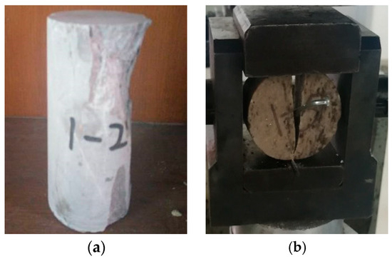
Figure 5.
Rock compression and splitting test. (a) Uniaxial compression test damage pattern (b) Splitting test damage pattern.

Table 1.
Material characteristics of sandstone specimens.
In the test, 2 # rock emulsion explosives with density ρ0 = 1.24 g/cm3 and explosive burst speed D = 4200 m/s are used. The charge has a diameter of dc = 32 mm, length of 300 mm, mass of 300 g, and blast hole diameter of db = 90 mm. The other parameters are calculated as follows: pk = 200 MPa, and the resulting axial uncoupling coefficient Kl is listed in Table 2 for different radial uncoupling coefficients for bare face blasting of the blast hole charge.
Table 2.
Selection of gunhole parameters for bare face holes.
5.2. Charging Structure and Parameter Selection
Smooth surface blasting technology was selected based on the slope situation and construction experience. During construction, the blasting parameters are modified in accordance with the flatness of the slope surface and the amount of rock fragmentation after blasting. The interval uncoupled charging structure is used. The volume of explosives is calculated according to the actual length of the blast hole. The explosive sections were evenly tied to a detonation cord. After charging is completed, the blocking is conducted using loess or rock powder. It should be ensured that the blockage does not contain stones. The detonating cord detonation network and electric detonator detonation are adopted.
(1) Packet production: the explosive roll is bound on a bamboo sheet, each explosive roll is connected with a detonating cable, and one end of the drug pack is tied with a detonating detonator.
(2) Charging: a segmental charging method is adopted. Under the condition of ensuring the filling length, strengthened charging is used at the bottom of the hole and weakened charging is used in the orifice segment. Normal charging is used on other segments.
(3) Plugging: To ensure that the high-pressure explosive gas does not leak, effective plugging is required. The plugging length should be 12–20 times the diameter of the blast hole. The blast hole should be tightly plugged with paper balls or bags in the lower part of the plugging section and then plugged solid with rock powder and clay.
A 90 mm diameter submersible drill is used for construction. Drilling is performed to the design depth twice at one time, and the vertical depth of the borehole H is 10 m. The blasting distance is taken as 1.2 m. The blasted section of the rock consists of moderately weathered or weakly weathered dolomite. The color of the rock is grayish white. Therefore, the super depth h of the hole is taken as 1.0 m.
The blast hole length L is calculated as L = (H + h)/sinα. The standard value of H is 10 m, the super depth h is 1.0 m, and the slope rate is 1:0.75. The standard blast hole length L is calculated to be 13.8 m. Emulsion explosives of diameter 32 mm meet the requirements of blasting.
When the radial uncoupling coefficient is Kd = 2.0 and axial uncoupling coefficient is K1 = 4, the structure of the charging is as shown in Figure 6a.
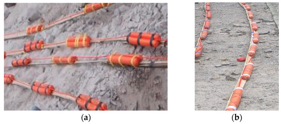
Figure 6.
Structure diagram of smooth-face hole charge. (a) Radial uncoupling factor 2.0. (b) Radial uncoupling factor 2.8.
When the radial uncoupling coefficient is Kd = 2.8 and axial uncoupling coefficient is K1 = 2.22, the structure of the charging is as shown in Figure 6b.
Both types of charge structures are applied in field operation and are found to produce satisfactory blasting results. The effect of road rift slope blasting is shown in Figure 7. The light explosion technique performs better, the marking rate of blast hole is 100%, and the newly create free surface does not appear to be overly broken, as shown in Figure 6a. As demonstrated in Figure 6b, the rock crushing effect is improved, and the crushing block size is reduced, making mechanical loading easier and improving slagging efficiency.
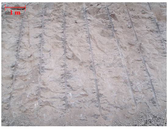
Figure 7.
Blasting effect diagram.
5.3. Research Significance
The development of drilling machinery and the requirements of construction efficiency means that large diameter surface blasting holes are gradually more widely used in engineering. The oversized uncoupling coefficient charge can better increase the quasi-static effect of the detonating gas and reduce the damage of the blast shock wave on the borehole, but the traditional theory of glossy blasting can no longer be well solved for the blasting parameters of the oversized uncoupling charge. Therefore, the large diameter surface blasting program can reasonably determine the axial and radial uncoupled charge coefficients and uncoupled charge under the action of the force on the wall of the borehole and the borehole spacing and can effectively improve the utilization of explosive energy and improve the effect of blasting.
From the bursting theory, one can explore the air spacing uncoupled charge in line with the multi-faceted exponential expansion critical uncoupling coefficient and according to the surface blasting and field charging structure requirements. Derivation of quasi-static pressure on the borehole wall under the action of large uncoupling, uncoupling coefficient and borehole spacing, and other parameters, along with the establishment of an axial uncoupling coefficient and radial uncoupling coefficient equivalence, put forward the uncoupling coefficient and the theoretical relationship between the selection of borehole spacing, revealing that the engineering practice of selecting different parameters of light surface blasting can achieve good results in the mechanism. In addition, a slope in Guizhou is an example of carrying out sample calculations and applications of two different charging structures applied to field loading, which have achieved a good effect from surface blasting. Application case blasting parameters and effects are shown in Table 3.
Table 3.
Blasting parameters of this case.
6. Conclusions
(1) According to the assumption of detonation, the theory of smooth blasting has certain limitations in the application of a large non-coupling coefficient charge in smooth blasting. Therefore, it is discussed from the detonation theory that the uncoupled charge of air space charge meets the critical uncoupling coefficient of multi-exponential expansion, and according to the structural requirements of smooth blasting and field charge, the equivalent relationship between an axial and radial uncoupling coefficient is established by deducing the quasi-static pressure, uncoupling coefficient, and hole spacing under a large uncoupling action. The theoretical relationship between an uncoupling coefficient and hole spacing is proposed, and it is revealed that the mechanism of selecting different smooth blasting parameters can achieve good results in engineering practices.
(2) A slope in Guizhou was taken as an example for calculations and applied to the field charge. There are two kinds of charge structures with large uncoupling coefficients on site: one is the explosive equivalent diameter of 45 mm, the gun hole diameter of 90 mm, the gun bore directional uncoupling of 2.0, and the axial uncoupling coefficient of 4.0; the other is the explosive equivalent diameter of 32 mm. The hole diameter is 90 mm, the uncoupling coefficient of the gun aperture is 2.8, and the axial uncoupling coefficient is 2.2. The two charging structures have obtained good smooth blasting effects in field applications.
Author Contributions
Conceptualization, M.W. and H.W.; methodology, M.W.; software, Q.Z.; validation, M.W. and H.W.; formal analysis, Q.Z.; investigation, F.X.; resources, Q.K.; data curation, H.W.; writing—original draft preparation, H.W.; writing—review and editing, M.W.; visualization, Y.P.; supervision, C.Z.; project administration, Q.Z.; funding acquisition, M.W. All authors have read and agreed to the published version of the manuscript.
Funding
Anhui University Scientific Research Project, China (No. 2022AH050841), and the National Natural Science Foundation of China (Grant No. 52209148). The open fund of State Key Laboratory of Coal Mine Disaster Dynamics and Control (2011DA105827-FW202209). Anhui Key Laboratory of Mining Construction Engineering (GXZDSYS2022101).
Institutional Review Board Statement
Not applicable.
Informed Consent Statement
Not applicable.
Data Availability Statement
The data presented in this study are available on request from the corresponding author.
Conflicts of Interest
The authors declare no conflict of interest.
References
- Feng, W.G.; Yang, Z.T. The application of surface blasting technology in the excavation of stone graben of high grade highway. Highway 2001, 2, 58–60. [Google Scholar]
- Guo, L.P. Application of smooth blasting in highway cutting construction. Railw. Eng. 2001, 5, 14–16. [Google Scholar]
- Tang, S.B.; Wang, J.X.; Chen, P.Z. Theoretical and numerical studies of cryogenic fracturing induced by thermal shock for reservoir stimulation. Int. J. Rock Mech. Min. Sci. 2020, 125, 104160. [Google Scholar] [CrossRef]
- Tang, S.B.; Huang, R.Q.; Wang, S.Y.; Bao, C.Y.; Tang, C.A. Study of the fracture process in heterogeneous materials around boreholes filled with expansion cement. Int. J. Solids Struct. 2017, 112, 1–15. [Google Scholar] [CrossRef]
- Hinzen, G. Comparison of seismic and explosive energy in five smooth blasting test rounds. Int. J. Rock Mech. Min. Sci. 1998, 35, 957–967. [Google Scholar] [CrossRef]
- Liu, K.; Liu, B. Optimization of smooth blasting parameters for mountain tunnel construction with specified control indices based on a GA and ISVR coupling algorithm. Tunn. Undergr. Space Technol. 2017, 70, 363–374. [Google Scholar] [CrossRef]
- Wu, X.; Gong, M.; Wu, H.; Hu, G.; Wang, S. Vibration reduction technology and the mechanisms of surrounding rock damage from blasting in neighbourhood tunnels with small clearance. Int. J. Min. Sci. Technol. 2023, 33, 625–637. [Google Scholar] [CrossRef]
- Li, X.; Liu, K.; Yang, J.; Sha, Y.; Song, R. Numerical study on the effect of in-situ stress on smooth wall blasting in deep tunnelling. Undergr. Space 2023, 11, 96–115. [Google Scholar] [CrossRef]
- Tang, S.B.; Zhang, H.; Tang, C.A.; Liu, H.Y. Numerical model for the cracking behavior of heterogeneous brittle solids subjected to thermal shock. Int. J. Solids Struct. 2016, 80, 520–531. [Google Scholar] [CrossRef]
- Tang, S.B.; Tang, C.A. Crack propagation and coalescence in quasi-brittle materials at high temperatures. Eng. Fract. Mech. 2015, 134, 404–432. [Google Scholar] [CrossRef]
- Tang, S.B.; Tang, C.A.; Zhu, W.C.; Wang, S.H.; Yu, Q.L. Numerical investigation on rock failure process induced by thermal stress. Chin. J. Rock Mech. Eng. 2006, 25, 2071–2078. (In Chinese) [Google Scholar]
- Chen, Y.D.; Sun, Z.M.; Xie, Y.; Tang, H.R.; Liu, Q.L.; Zhang, Y.P. Influence of air deck charging on blasting effect. J. BGR Imm. 1993, 2, 8–13. (In Chinese) [Google Scholar]
- Du, J.; Luo, Q.; Zong, Q. Analysis on preliminary shock pressure on borehole ofair-de-coupling charging. J. Xi’an Univ. Sci. Technol. 2007, 25, 347–351. [Google Scholar]
- Xu, Y.; Zong, Q. Theoretical analysis on the parameters of smooth blasting soft mat layer charging construction. J. China Coal Soc. 2000, 25, 610–613. [Google Scholar]
- Ling, W.M. A study on the fracture mechanism of smooth blasting and pre-split blasting. J. China Univ. Min. Technol. 1990, 19, 82–90. [Google Scholar]
- Monjezi, M.; Dehghani, H. Evakuation of effect of blasting pattern parameters on back break using neural networks. Int. J. Rock Mech. Min. Sci. 2008, 45, 1446–1453. [Google Scholar] [CrossRef]
- Kumar, R.; Kumaraswamidhas, L.; Murthy, V.; Vettivel, S. Experimental investigations on the machine vibration in blast-hole drills and optimization of operating parameters. Measurement 2019, 145, 803–819. [Google Scholar] [CrossRef]
- Bai, R.; Zhang, P.; Zhang, Z.; Sun, X.; Fei, H.; Bao, S.; Hu, G.; Li, W. Optimization of blasting parameters and prediction of vibration effects in open pit mines based on deep neural networks. Alex. Eng. J. 2023, 70, 261–271. [Google Scholar] [CrossRef]
- Monjezi, M.; Khoshalan, H.; Yazdian Varjani, A. Optimization of open pit blast parameters using Genetic Algorithm. Int. J. Rock Mech. Min. Sci. 2011, 48, 864–869. [Google Scholar] [CrossRef]
- Liu, D.; Lu, W.; Yang, J.; Gao, J.; Yan, P.; Hu, S.; Yao, C. Relationship between cracked-zone radius and dominant frequency of vibration in tunnel blasting. Int. J. Rock Mech. Min. Sci. 2022, 160, 105249. [Google Scholar] [CrossRef]
- Li, X.; Liu, K.; Sha, Y.; Yang, J.; Song, R. Numerical investigation on rock fragmentation under decoupled charge blasting. Comput. Geotech. 2023, 157, 105312. [Google Scholar] [CrossRef]
- Qin, G.F.; Zeng, C.; Xu, J.F.; He, R. Numerical simulation and engineering validation of faceted blasting in gray rock tunnels based on HJC damage ontology modeling. Explos. Mater. 2022, 51, 45–51. [Google Scholar]
- Tian, H.; Zhang, Y.P.; Wang, B.; Dai, Y.; Zhu, B. Experimental study on the effect of uncoupled charging on the effect of concrete blasting. Blasting 2019, 36, 25–30+42. [Google Scholar]
- Xiong, F.; Zhu, C.; Feng, G.; Zheng, J.; Sun, H. A three-dimensional coupled thermo-hydro model for geothermal development in discrete fracture networks of hot dry rock reservoirs. Gondwana Res. 2023, 122, 331–347. [Google Scholar] [CrossRef]
- Chen, W.J.; Wang, D.M.; Wang, Y.F. Test and application of high stage side smooth blasting in Zhangzhuang Iron Mine. Blasting 2021, 38, 58–63+115. [Google Scholar]
- Wang, G.; Zhao, B.; Wu, B.; Zhang, C.; Liu, W. Intelligent prediction of slope stability based on visual exploratory data analysis of 77 in situ cases. Int. J. Min. Sci. Technol. 2023, 33, 49–61. [Google Scholar] [CrossRef]
- Zhao, B.; Wang, G.; Wu, B.; Kong, X. A study on mechanical properties and permeability of steam-cured mortar with iron-copper tailings. Constr. Build. Mater. 2023, 383, 131372. [Google Scholar] [CrossRef]
- Lei, Z.; Wu, B.; Wu, S.; Nie, Y.; Cheng, S.; Zhang, C. A material point-finite element (MPM-FEM) model for simulating three-dimensional soil-structure interaction with hybrid contact method. Comput. Geotech. 2022, 152, 105009. [Google Scholar] [CrossRef]
- Azadi, P.; Elwan, H.; Klock, R.; Engell, S. Improved operation of a large-scale blast furnace using a hybrid dynamic model based optimizing control scheme. J. Process Control. 2023, 129, 103032. [Google Scholar] [CrossRef]
- Hosseini, S.; Mousavi, A.; Monjezi, M.; Khandelwal, M. Mine-to-crusher policy: Planning of mine blasting patterns for environmentally friendly and optimum fragmentation using Monte Carlo simulation-based multi-objective grey wolf optimization approach. Resour. Policy 2022, 79, 103087. [Google Scholar] [CrossRef]
- Yin, Q.; Liu, R.C.; Jing, H.W.; Su, H.J.; Yu, L.Y.; He, L.X. Experimental study of nonlinear flow behaviors through fractured rock samples after high-temperature exposure. Rock Mech. Rock Eng. 2019, 52, 2963–2983. [Google Scholar] [CrossRef]
- Yin, Q.; Wu, J.Y.; Zhu, C.; He, M.C.; Meng, Q.; Jing, H.W. Shear mechanical responses of sandstone exposed to high temperature under constant normal stiffness boundary conditions. Geomech. Geophys. Geo Energy Geo-Resour. 2021, 7, 1–17. [Google Scholar] [CrossRef]
- Yin, Q.; Wu, J.Y.; Zhu, C.; Wang, Q.; Xie, J.Y. The role of multiple heating and water cooling cycles on physical and mechanical responses of granite rocks. Geomech. Geophys. Geo Energy Geo Resour. 2021, 7, 69. [Google Scholar] [CrossRef]
- Zong, Q.; Meng, D. Theoretical study on influence of hole with different charge structure to blasting engineering. Chin. J. Rock Mech. Eng. 2003, 22, 641–645. [Google Scholar]
- Gao, J.S.; Yang, J. Study on rock blasting crack development direction and mechanics under simu-static pressure effects. Explos. Shock. Waves 1990, 10, 76–83. [Google Scholar]
- Zhang, Z.X. An empirical relation between mode I fracture toughness and the tensile rength of rock. Int. J. Rock Mech. Min. Sci. 2002, 39, 401–406. [Google Scholar] [CrossRef]
Disclaimer/Publisher’s Note: The statements, opinions and data contained in all publications are solely those of the individual author(s) and contributor(s) and not of MDPI and/or the editor(s). MDPI and/or the editor(s) disclaim responsibility for any injury to people or property resulting from any ideas, methods, instructions or products referred to in the content. |
© 2023 by the authors. Licensee MDPI, Basel, Switzerland. This article is an open access article distributed under the terms and conditions of the Creative Commons Attribution (CC BY) license (https://creativecommons.org/licenses/by/4.0/).