Abstract
In this research, the design of a robust curved-line path-following control system for fixed-wing unmanned aerial vehicles (FWUAVs) affected by uncertainties on the latitude plane is studied. This is undertaken to enhance closed-loop system robustness under unknown uncertainties and derive the control surface deflection angle directly used to control FWUAVs, which has rarely been studied in previous works. The system is formed through the mass center position control (MCPC) and yaw angle control (YAC) subsystems. In the MCPC, the desired yaw angle, which is treated as the reference signal for the YAC subsystem, is calculated analytically using path-following errors, current flow angles, and the yaw angle. In the YAC, a disturbance estimator is designed to estimate uncertainties such as nonlinearities, couplings, time variations, model parameter perturbations, and unmodeled dynamics. Predictive functional controllers are designed to target nominal systems in the absence of uncertainties, such that the estimations of the uncertainties can be incorporated through feedback for closed-loop system robustness enhancement. The simulation results show that higher path-following precision and stronger robustness for the FWUAVs based on the proposed approach can be achieved using only rough model parameters compared with the conventional nonlinear dynamic inversion, which requires detailed model information.
1. Introduction
Due to the advantages of long endurance, fast flight, and high energy availability, fixed-wing unmanned aerial vehicles (FWUAVs) have become increasingly attractive in many areas, such as reconnaissance, patrol inspection, and monitoring. When executing missions, FWUAVs are required to follow a prescribed reference path. The mission execution effect relies on the path-following control performance, making the design of the path-following control system important with engineering significance.
Path-following errors are adjusted via attitude angles. According to the path-following errors, the mass center position controller generates the desired attitude angles, which are regarded as the references for the attitude controller so that the control surface deflection angles as well as the control laws of FWUAVs can be derived.
In the MCPC, establishing a motion model is quite important. By considering aerodynamic complexities, variable couplings, fast time variations, and high nonlinearities, the geometric approach and control technique are mainly applied for model establishment. The two approaches have the advantages of a simple model structure and irrelevant model information, such that their superiority is obvious when compared with conventional modeling methods [1].
The commonly utilized geometric approaches include the line-of-sight (LOS) [2,3,4,5,6,7], vector field [8,9,10,11,12,13,14], virtual target following [15,16,17,18,19,20,21], and L1 guidance approaches [22,23,24,25,26,27,28]. Analytical solutions of the desired attitude angles or body rates regarded as reference signals can be derived through the relationships among the path-following errors, the current flow angles, and the current attitude angles.
Being different from the geometric approach, the control technique assumes that there is a virtual target point attached to the prescribed reference path. A natural frame also named the Frenet frame [21,29,30,31,32], whose origin coincides with the virtual target point, is established; in this case, the Frenet frame overlaps with the body frame if the FWUAV can strictly follow the path. In the control technique, path-following error kinematic models whose inputs are the error angles (also called error attitude angles) between the Frenet frame and the body frame are built without using any plant model information. The advantages of the control technique are that the error attitude angles can be designed through different control theories, such as L1 adaptive control [33], L1 state feedback control [34], nested saturation control [35], linear model-based predictive control [36], optimal control [37], and nonlinear model predictive control [38], and that the approach has been studied widely.
By considering that FWUAVs are easily influenced via external wind fields, approaches such as a new guidance law combined with pure pursuit and the LOS [39], a VTP-based nonlinear guidance law [15], optimal control with the wind amplitude available [16], feedback control with wind estimation and compensation [37], and adaptive backstepping control [40] have been presented.
However, the existing path-following control schemes are incomplete since they mainly focus on the establishment of a path-following error kinematic model and the design of mass center position controllers. Once the desired attitude angles/body rates have been obtained, the studies are ceased, meaning that the design of the attitude controllers is ignored and that the final deflection laws of the control surfaces actually used to steer the FWUAVs are not given. It is well known that attitude control plays a decisive role not only in path-following control but also in the field of flight control. Hence, the design of an attitude control system and control performance enhancement cannot be ignored.
To address these problems, targeting the movement of FWUAVs on the latitude plane, a robust path-following control approach is presented in this paper. The path-following control performance can be improved using only a small amount of rough dynamic model information. The main outcomes and contributions of this paper are twofold:
- (1)
- A path-following control scheme for FWUAVs is perfected.
Being different from most existing studies, this paper aims to improve attitude system performance via improving path-following control performance. Effective deflection angles of the control surfaces as well as the control laws are designed;
- (2)
- A robust control approach is proposed for attitude control.
A novel disturbance estimator (DE) [41,42] is applied to estimate uncertainties, such as nonlinearities, strong couplings, and system unmodeled dynamics, so that, in the design of controllers, only a small amount of model information is used. As pointed out in the two literatures, the novel DE has better performance than the commonly used extended state observer [43,44,45,46,47,48]. In addition, a predictive functional controller (PFC) is designed for the nominal system in the absence of uncertainties to improve system input/output performance. The estimation of the uncertainties is incorporated into the PFC for feedback compensation so that the closed-loop system’s robustness can be improved.
2. System Modeling
In this section, a movement model based on the latitude plane is established. The fundamentals of the curved path following the latitude plane are illustrated in Figure 1.
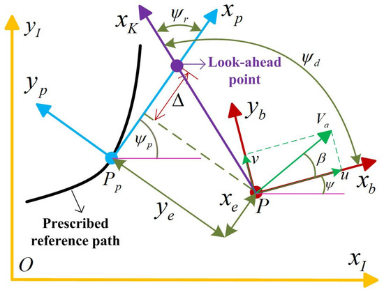
Figure 1.
Path following on the latitude plane.
Here, and represent the inertia frame and body frame, respectively. represents the current mass center position of the FWUAV, which is denoted as . represents the desired position denoted as , which the FWUAV should locate. and are the velocities along and , respectively. represents the side-slip angle. is the air speed. is the yaw angle. and represent the components between the current position and the desired position in the frame . is the look-ahead distance, which is a positive number.
2.1. Computation of Desired Attitude Angles
The prescribed reference path is denoted as , with representing the path parameter and and being the second-order derivatives with respect to . Then, the desired path angle can be written as
where represents the quadrant function.
The transformation matrix from to can be given using
The following errors can be computed using Figure 1:
Differentiating Formula (3) relative to time yields
One can also have
The transformation matrix from to can be given using
By considering the wind velocities along and denoted as and , respectively, the perturbed airspeed denoted by can be calculated using .
Since , we can have
The velocity of the desired path in can be expressed as ; then, we can derive
and
where represents the norm of a vector.
It can be determined from Formula (10) that
where and .
Bringing Formulas (5), (8), and (9) into (4) yields
Then, the desired yaw angle can be calculated as
with defined as
Take the following Lyapunov function:
Differentiating the Lyapunov function relative to time yields
It is easy to prove that . Then, via carrying out a simple mathematical operation, one can derive
To guarantee , we can take
where is a tuning variable.
Bringing Formula (18) into (11) yields
Bringing Formulas (14) and (18) into (17) yields
It can be seen from the definition that the velocity must be a positive number. is the look-ahead distance, which is a positive number and has also been defined before. Thus, and can guarantee , which also implies . Formula (20) indicates that the real flight path of the FWUAV can converge gradually to the prescribed reference path under the designed desired yaw angle (14).
The complete curved path-following scheme can be summarized as follows:
Equation (21) describes the path-following error of the center of mass of the FWUAV. The first equation describes the changing rate of the path variable relative to time so that the desired path to be followed can be digitalized and programmed in the flight control hardware. The rest of the two equations afford reference signals to the yaw angle system to design the deflection laws of the rudder.
2.2. Yaw System Model
In the yaw movement, the force acting on the FWUAV is mainly the yaw torque, which depends on the rudder. The expression of the yaw torque is given by [49]:
where , , , and are the air density, wing area, wing span, and rudder deflection angle, respectively. is the yaw rate. is the zero yaw moment coefficient. , , and are derivatives of the yaw moment with respect to the side-slip angle, yaw rate, and rudder, respectively, which can also be seen in [49].
Then, by referring to [49] and considering uncertainties, the yaw movement model is given using
where is the moment of inertia. represents the uncertainties, including the unmodeled dynamics and model parameter perturbations.
Then, the remaining task of this paper is to design the deflection angle of the rudder so that the yaw angle of the FWUAV in Formula (23) can track the desired value of derived from Formula (21) using the dynamic model (23).
2.3. Existing Approaches and Defects
To highlight the approach proposed in the paper, the existing approaches and their defects are summarized in Table 1.

Table 1.
The existing approaches and their defects.
3. Yaw Angle Control Design
In this section, based on the desired yaw angle derived in Section 2.1, a control scheme for the yaw movement can be designed.
3.1. Design of DE
By referring to the literature [41], the design of the DE for estimating the nonlinear term can be divided into the following steps:
Step 1: design of the nominal model
In the absence of in Formula (23), the nominal model in the continuous-time domain can be given using
The discrete-time version is written as
where is the state of the nominal model, and is the sampling period;
Step 2: DE formulation
The DE is designed as follows:
where is the estimated value of , , , , , , , and is specified by users.
A stability analysis of the DE can be seen in Appendix C in [42].
3.2. Controller Design
In Formula (23), the desired yaw rate for manipulating the yaw angle is designed as follows:
According to the predictive functional control theory [50,51], the system input can be formulated using
Then, in Formula (23), in the absence of , a predictive model for the yaw rate model can be given using
The following receding horizon performance index function is selected:
where and , which are two positive integers, are the lengths of the receding horizon.
Denote . Then, by letting , the optimal rudder deflection angle can be derived as follows:
Through combing Formulas (26) and (31), the final control law is summarized as
4. Numerical Simulations
In this section, two groups of numerical simulations are carried out to demonstrate the effectiveness and superiority of the proposed control scheme via a comparison with the conventional nonlinear dynamic inversion (NDI) approach [52,53,54], which is commonly used in flight control. The conventional nonlinear dynamic inversion controller for the yaw angle control is designed as follows:
where and are two tuning parameters.
The geometry and aerodynamic parameters in Formulas (22) and (23) are , , , , and . The trimmed conditions of the FWUAV are , , , and . The values of the controller parameters for the NDI are and . The values of the controller parameters for the proposed approach are , , , , , and . The uncertainty term is when , and the wind velocities along and are 0 and 3 m/s when , respectively. Actually, the wind disturbances along would not have great effects on the flight path of the FWUAV since the wind can only decrease the flight speed and prolong the mission accomplishment time of the path following. However, the wind along has entirely different effects on the FWUAV since it affects the airplane from the side direction, which would influence the stability of the FWUAV.
The prescribed reference path (unit: m) is given using
4.1. Case Study 1
In this group, wind disturbances along and and the uncertainty of regeared as unmodeled dynamics are considered. The unmodeled dynamics would affect the flight stability of the FWUAV since it can cause unstable poles.
The simulation results are illustrated below.
Figure 2 and Figure 3 clearly prove that the proposed approach is superior to the NDI approach. The absolute maximum following errors of the proposed scheme along and are only 0.02 m and 2 m, respectively, compared with the ones based on the NDI approach, which are up to 0.12 m and 12 m along and , respectively. The path-following errors of the proposed approach are much smaller than those of the NDI. Additionally, the two figures also indicate that the NDI approach has a trend of divergence after 45 s when the unmodeled dynamics are encountered, since the NDI approach does not have any anti-disturbance mechanisms. However, the situations are different in the proposed scheme due to the existence of the DE, which has a strong disturbance estimation capability and superb estimation accuracy.
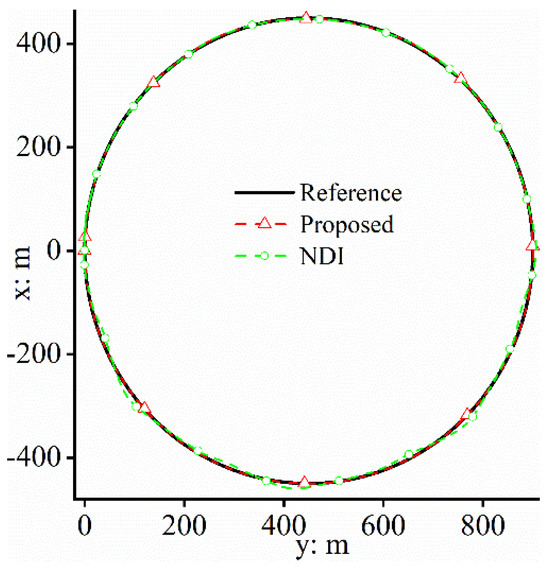
Figure 2.
Path−following effect.
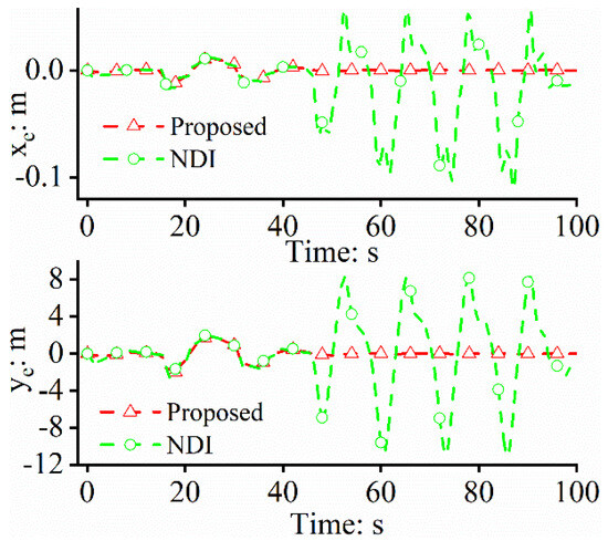
Figure 3.
Path−following errors.
Figure 4 shows that, when dealing with wind disturbances, the controllers of the proposed approach generate more effective control inputs than those of the NDI approach to guarantee path-following precision. However, to deal with the unknown unmodeled dynamics, too-frequent deflection for the rudder occurs in the NDI-based closed-loop system, which places a heavy burden on the actuator of the FWUAV. The reason for this is that the closed-loop system based on the proposed control scheme has a disturbance rejection mechanism that enables the FWUAV’s strong robustness. Figure 5 shows the accurate estimation capability of the DE, which is the fundamental reason for the proposed control approach being superior to the conventional NDI approach.
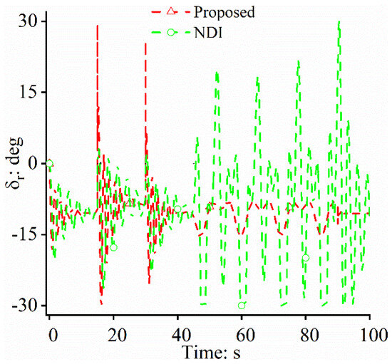
Figure 4.
Control laws.
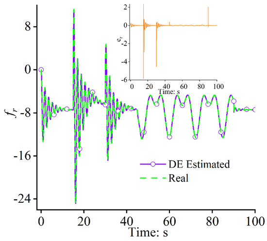
Figure 5.
Uncertainty estimation and estimation error .
Figure 6, Figure 7 and Figure 8 show the attitude control performance of the FWUAV during flight. In the flight control field, attitude maintenance capability plays a decisive role and determines path-following performance. In Figure 7 and Figure 8, the NDI approach-based path-following control system is incapable of steering the yaw movement when unmodeled dynamics are encountered. It can be seen in Figure 7 that the yaw angle of the NDI approach has frequent fluctuations. In Figure 8, the FWUAV has large changing rates, which reach up to 30 degrees (should be around zero) for the yaw movement. A poor attitude control capability would cause large path-following errors for the FWUAV, which results in unsatisfying control performance in path-following missions. The situations are quite different in the proposed approach, as shown in Figure 6, due to the disturbance rejection function because the unmodeled dynamics can be estimated and compensated successfully.
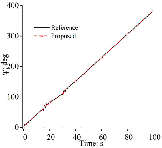
Figure 6.
Yaw angles: proposed approach.
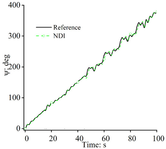
Figure 7.
Yaw angles: the NDI approach.
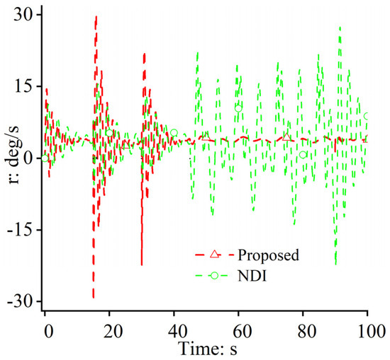
Figure 8.
Yaw rates.
4.2. Case Study 2
In this group, all uncertainties, including wind disturbances along and , the model parameter perturbations for , and uncertainty , are considered. To validate the proposed scheme completely, +30% and −30% perturbations of are considered. Furthermore, the results of the two perturbation cases are also combined with those of the case without any perturbations to show the effectiveness of the proposed scheme.
The simulation results are illustrated below.
It can be determined from Figure 9 and Figure 10 that the proposed approach-based path-following control system can achieve great flight performance regardless of whether the important model parameter has perturbations. The absolute maximum following error of the proposed approach in the two situations along is only 0.02 m, and the mean path-following errors are all very close to zero. Additionally, when recalling the results in Section 4.1, it is found that, even when the model parameter perturbs within a wide range, the control performance of the proposed approach is much better than that of the NDI.
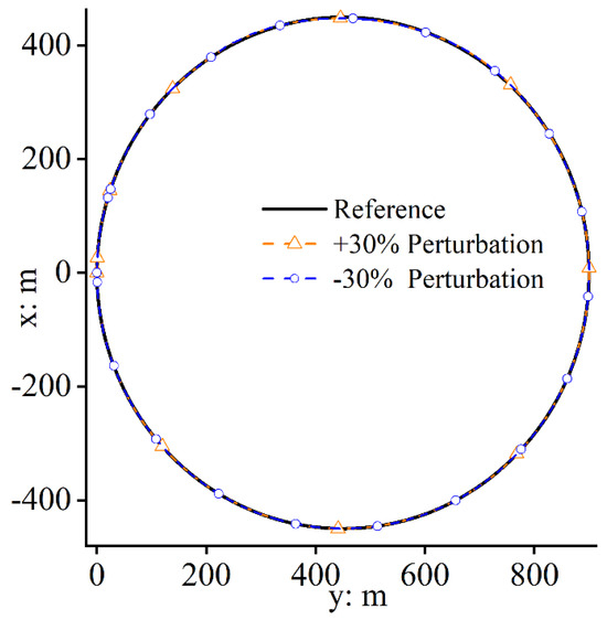
Figure 9.
Path−following effects.
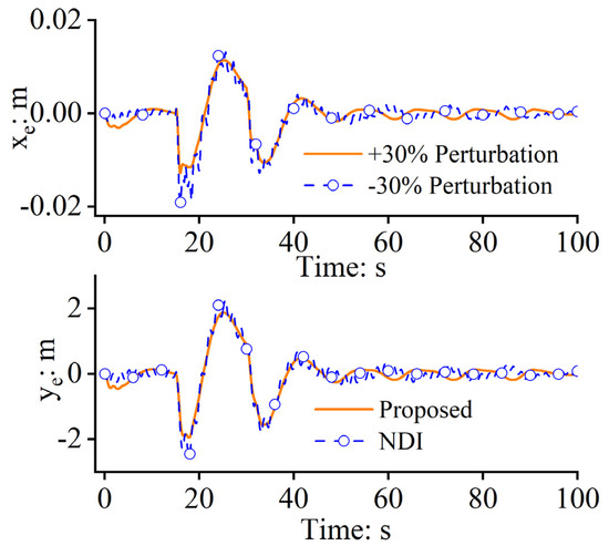
Figure 10.
Path−following errors.
Figure 11 shows that the control law can be designed requiring only a small amount of rough model information. In addition, due to the existence of the DE, the dynamics of the model perturbation can be observed accurately and compensated effectively so that even slight changes in the characteristics of the closed-loop system would not happen. Thus, the trends of the rudder deflection angles in the two situations are similar, which means that even the model parameter undergoes large perturbations, and the rudder deflection angles similar to those in the case without any perturbations can be used to steer the FWUAV. Figure 12 and Figure 13 show that the DE can estimate the uncertainties accurately, even when large perturbations occur in the model parameter. It has an advantage in that the design of the control system for the FWUAV is mildly correlated with the system modeling and model parameter measurement.
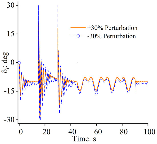
Figure 11.
Control laws.
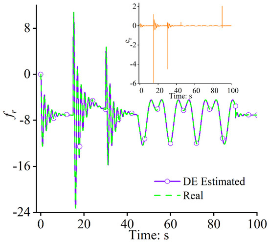
Figure 12.
Uncertainty estimation: +30% and estimation error .
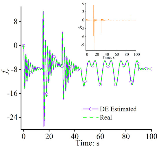
Figure 13.
Uncertainty estimations: −30% and estimation error .
Figure 14, Figure 15 and Figure 16 show that similar yaw movements in the two situations can be achieved during path following. Under the uncertainties induced via the unmodeled dynamics and the parameter perturbation, the yaw angle changes stably without any jumping or fluctuation, which proves that the frame stability of the FWUAV can be guaranteed and that the closed-loop system’s robustness can be significantly enhanced under large model parameter perturbations.
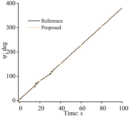
Figure 14.
Yaw angles: +30%.

Figure 15.
Yaw angles: −30%.
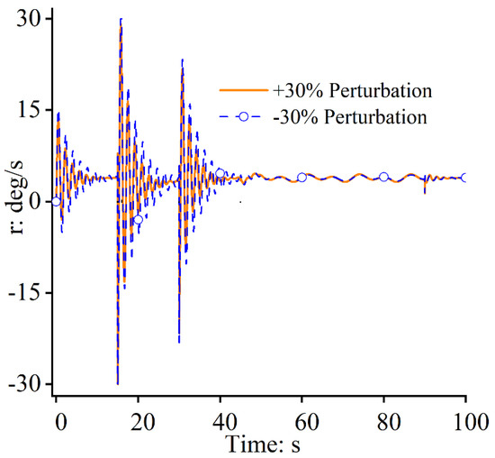
Figure 16.
Yaw rates.
5. Conclusions
In this study, a novel, robust flight control system was designed for FWUAVs following curved paths under uncertainties on the latitude plane. Without using any model information, the desired yaw angle can be derived by using path-following errors, flow angles, and the current yaw angle. The model-free approach for deriving the desired yaw angle is easy to implement in hardware for engineering applications, and it dramatically reduces the burden of flight control computers. For the yaw angle control, firstly, though the yaw movement system is full of nonlinearities, couplings, time variations, and external winds, which would seriously degrade flight performance, the designed disturbance estimator can estimate all the uncertainties existing in the yaw movement model accurately for feedback compensation such that the path-following accuracy can be improved significantly. The path-following errors for the x and y directions are only 0.02 m and 2 m, respectively, compared with 0.12 m and 12 m for the NDI approach. Secondly, due to the existence of the disturbance estimator, the frame parameters of FWUAVs are allowed to perturb within a wide range between −30% and +30%. Through consuming quite a similar amount of input power (the deflection angles of the rudder), almost the same path-following control performance with very small path-following errors can be achieved. The yaw system has strong robustness in dealing with uncertainties, which allows the desired yaw angle of the position system to be tracked precisely. The yaw rate has small fluctuations in situations where external wind fields are encountered. However, the yaw rate can return to a stable value within a short time period.
Author Contributions
Conceptualization, M.T. and W.Q.; Methodology, W.Q.; Validation, W.Q.; Formal analysis, W.Q.; Investigation, Q.W.; Resources, W.S.; Writing—original draft, W.Q.; Writing—review & editing, M.T.; Supervision, H.Y. All authors have read and agreed to the published version of the manuscript.
Funding
This research received no external funding.
Institutional Review Board Statement
Not applicable.
Informed Consent Statement
Not applicable.
Data Availability Statement
The supporting information is shared and available online by visiting https://github.com/maggie48dy/english-nal (accessed on 22 October 2023).
Conflicts of Interest
The authors declare no conflict of interest.
References
- Nelson, R.C. Flight Stability and Automatic Control; The McGraw-Hill Companies Press: New York, USA, 1989. [Google Scholar]
- Ambrosino, G.; Ariola, M.; Ciniglio, U.; Corraro, F.; De Lellis, E.; Pironti, A. Path generation and tracking in 3-D for UAVs. IEEE Trans. Control Syst. Technol. 2009, 17, 980–988. [Google Scholar] [CrossRef]
- Woo, J.W.; An, J.Y.; Cho, M.G.; Kim, C.J. Integration of path planning, trajectory generation and trajectory tracking control for aircraft mission autonomy. Aerosp. Sci. Technol. 2021, 118, 107014. [Google Scholar] [CrossRef]
- Tan, G.Y.; Luo, H.B.; Liao, F.; Wang, X.H.; Ji, H.B. Cooperative Strategy for Aircraft Defense Line-of-Sight Guidance in Three-Dimensional Space. In Proceedings of the 2022 41st Chinese Control Conference (CCC), Hefei, China, 25–27 July 2022; pp. 3398–3403. [Google Scholar]
- Gu, J.C.; Ding, G.R.; Xu, Y.T.; Wang, H.C.; Wu, Q.H. Proactive optimization of transmission power and 3D trajectory in UAV-assisted relay systems with mobile ground users. Chin. J. Aeronaut. 2021, 34, 129–144. [Google Scholar] [CrossRef]
- Rymer, N.; Moore, A.J.; Young, S.; Glaab, L.; Smalling, K.; Consiglio, M. Demonstration of Two Extended Visual Line of Sight Methods for Urban UAV Operations. In Proceedings of the AIAA AVIATION 2020 Forum, Virtual, 15–19 June 2020; p. 2889. [Google Scholar]
- Li, S.W.; Gu, Y.X.; Subedi, B.; He, C.Y.; Wan, Y.; Miyaji, A.; Higashino, A. Beyond Visual Line of Sight UAV Control for Remote Monitoring using Directional Antennas. In Proceedings of the 2019 IEEE Globecom Workshops, Waikoloa, HI, USA, 9–13 December 2019; pp. 1–6. [Google Scholar]
- Nelson, D.R.; Blake Barber, D.; McLain, T.W.; Beard, R.W. Vector Field Path Following for Miniature Air Vehicles. IEEE Trans. Robot. 2007, 23, 519–529. [Google Scholar] [CrossRef]
- Wilhelm, J.; Clem, G.; Casbeer, D.; Gerlach, A. Circumnavigation and obstacle avoidance guidance for UAVs using Gradient Vector Fields. In Proceedings of the AIAA Sci tech 2019 Forum, San Diego, CA, USA, 7–11 January 2019; pp. 1–15. [Google Scholar]
- Wilhelm, J.P.; Clem, G. Vector Field UAV Guidance for Path Following and Obstacle Avoidance with Minimal Deviation. J. Guid. Control Dyn. 2019, 42, 1848–1856. [Google Scholar] [CrossRef]
- Chang, K.; Ma, D.L.; Han, X.B.; Liu, N.; Zhang, B.B. Lyapunov vector-based formation tracking control for unmanned aerial vehicles with obstacle/collision avoidance. Trans. Inst. Meas. Control 2020, 42, 1–8. [Google Scholar] [CrossRef]
- Luo, Y.L.; Huang, X.Y.; Wu, C.F.; Leng, S.P. Enhanced Artificial Potential Field-based Moving Obstacle Avoidance for UAV in Three-Dimensional Environment. In Proceedings of the 2020 IEEE 16th International Conference on Control & Automation (ICCA), Singapore, 9–11 October 2020; pp. 177–182. [Google Scholar]
- Zheng, X.; Galland, S.; Tu, X.; Yang, Q.; Lombard, A.; Gaud, N. Obstacle avoidance model for UAVs with joint target based on multi-strategies and follow-up vector field. In Proceedings of the 11th International Conference on Ambient Systems, Networks and Technologies (ANT), Warsaw, Poland, 6–9 April 2020; pp. 257–264. [Google Scholar]
- Wang, X.; Wang, H.; Lun, Y.B. Shortest Path Planning of UAV for Target Tracking and Obstacle Avoidance in 3D Environment. In Proceedings of the 39th Chinese Control Conference, Shenyang, China, 27–29 July 2020; pp. 3385–3390. [Google Scholar]
- Park, S.; Deyst, J.; How, J.P. Performance and Lyapunov stability and of a nonlinear path following guidance method. J. Guid. Control Dyn. 2007, 30, 1718–1728. [Google Scholar] [CrossRef]
- Rucco, A.; Aguiar, A.P.; Pereira, F.L.; de Sousa, J.B. A Predictive Path-Following Approach for Fixed-Wing Unmanned Aerial Vehicles in Presence of Wind Disturbances. In Proceedings of the Robot 2015: Second Iberian Robotics Conference, Lisbon, Portugal, 2 December 2015; pp. 623–634. [Google Scholar]
- Yamasaki, T.; Balakrishnan, S.N.; Takano, H. Separate-Channel Integrated Guidance and Autopilot for Automatic Path-Following. J. Guid. Control Dyn. 2013, 36, 25–34. [Google Scholar] [CrossRef]
- Rysdyk, R. Unmanned Aerial Vehicle Path Following for Target Observation in Wind. J. Guid. Control Dyn. 2006, 29, 1092–1100. [Google Scholar] [CrossRef]
- Chen, Q.; Wang, X.G.; Yang, J.; Wang, Z.Y. Trajectory-following guidance based on a virtual target and an angle constraint. Aerosp. Sci. Technol. 2019, 87, 448–458. [Google Scholar] [CrossRef]
- Cai, Z.H.; Wang, L.H.; Zhao, J.; Wu, K.; Wang, Y.X. Virtual target guidance-based distributed model 4 predictive control for formation control of multiple 5 UAVs. Chin. J. Aeronaut. 2020, 33, 1037–1056. [Google Scholar] [CrossRef]
- Chen, H.; Wang, X.K.; Shen, L.C.; Cong, Y.R. Formation flight of fixed-wing UAV swarms: A 4 group-based hierarchical approach. Chin. J. Aeronaut. 2021, 34, 504–515. [Google Scholar] [CrossRef]
- Mao, Y.H.; Chen, Q.Y.; Hou, Z.X.; Zheng, G. An improved nonlinear guidance law for unmanned aerial vehicles path following. In Proceedings of the 2015 34th Chinese Control Conference (CCC), Hangzhou, China, 28–30 July 2015; pp. 5271–5276. [Google Scholar]
- Park, S.; Deyst, J.; How, J. A New Nonlinear Guidance Logic for Trajectory Tracking. In Proceedings of the AIAA Guidance, Navigation, and Control Conference and Exhibit, Providence, RI, USA, 16–19 August 2004; pp. 1–16. [Google Scholar]
- Zhou, W.H.; Li, J.; Liu, Z.H.; Shen, L.C. Improving multi-target cooperative tracking guidance for UAV swarms using multi-agent reinforcement learning. Chin. J. Aeronaut. 2022, 35, 100–112. [Google Scholar] [CrossRef]
- Ueba, M.; Takaku, Y.; Takahashi, K.; Kamata, T. Design and Tests of Guidance and Control Systems for Autonomous Flight of a Low-Speed Model Airplane for Application to a Small-Scale Unmanned Supersonic Airplane. Trans. Jpn. Soc. Aeronaut. Space Sci. Aerosp. Technol. Jpn. 2019, 17, 220–226. [Google Scholar] [CrossRef]
- Modali, S.; Ghosh, S. Terminal-Angle-Constrained Guidance based on Sliding Mode Control for UAV Soft Landing on Ground Vehicles. Electr. Eng. Syst. Sci. 2020, 2009, 14748. [Google Scholar]
- Yin, H.; Li, D.G.; Wang, Y.; Li, X.P. Adaptive Dynamic Occupancy Guidance for Air Combat of UAV. Unmanned Syst. 2023, 11, 1–18. [Google Scholar] [CrossRef]
- Tan, Y.Y.; Tang, W.X. Guidance Strategy for UAV Tracking Target Based on Reference Point Guidance Method. J. Northwest. Polytech. Univ. 2020, 38, 176–182. [Google Scholar] [CrossRef]
- Cui, Z.Y.; Wang, Y. Nonlinear Adaptive Line-of-Sight Path Following Control of Unmanned Aerial Vehicles considering Sideslip Amendment and System Constraints. Math. Probl. Eng. 2020, 2020, 1–11. [Google Scholar] [CrossRef]
- Wang, Y.Z.; Wang, D.W.; Zhu, S.Q. Cooperative moving path following for multiple fixed-wing unmanned aerial vehicles with speed constraints. Automatica 2019, 100, 82–89. [Google Scholar] [CrossRef]
- Ma, C.; Yang, J.; Chen, J.Y.; Zhou, C. Path following identification of unmanned aerial vehicles for navigation spoofing and its application. ISA Trans. 2021, 108, 393–405. [Google Scholar] [CrossRef]
- Sedlmair, N.; Theis, J.; Thielecke, F. Design and Experimental Validation of UAV Control Laws—3D Spline-Path-Following and Easy-Handling Remote Control. In Proceedings of the 5th CEAS Conf. Guid., Navigation, Control, Milano, Italy, 3–5 April 2019; pp. 1–20. [Google Scholar]
- Kaminer, I.; Pascoa, A.; Xargay, E.; Hovakimyan, N.; Cao, C.Y.; Dobrokhodov, V. Path following for unmanned aerial vehicles using L1 adaptive augmentation of commercial autopilots. J. Guid. Control Dyn. 2010, 33, 550–564. [Google Scholar] [CrossRef]
- Liu, C.J.; McAree, O.; Chen, W.H. Path-following control for small fixed-wing unmanned aerial vehicles under wind disturbances. Int. J. Robust. Nonlinear Control 2013, 23, 1682–1698. [Google Scholar] [CrossRef]
- Beard, R.W.; Ferrin, J.; Humpherys, J. Fixed wing UAV path following in wind with input constraints. IEEE Trans. Control Syst. Technol. 2014, 22, 2103–2117. [Google Scholar] [CrossRef]
- Gavilan, F.; Vazquez, R.; Camacho, E.F. An iterative model predictive control algorithm for UAV guidance. IEEE Trans. Aerosp. Electron. Syst. 2015, 51, 2406–2419. [Google Scholar] [CrossRef]
- Yang, J.; Liu, C.J.; Coombes, M.; Yan, Y.D.; Chen, W.H. Optimal path following for small fixed-wing UAVs under wind disturbances. IEEE Trans. Control Syst. Technol. 2020, 29, 996–1008. [Google Scholar] [CrossRef]
- Jackson, S.; Tisdale, J.; Kamgarpour, M.; Basso, B.; Karl Hedrick, J. Tracking controllers for small UAVs with wind disturbances: Theory and flight results. In Proceedings of the 2008 47th IEEE Conference on Decision and Control, Cancun, Mexico, 9–11 December 2008; pp. 564–569. [Google Scholar]
- Kothari, M.; Postlethwaite, I.; Gu, D.W. A suboptimal path planning algorithm using rapidly-exploring random trees. Int. J. Aerosp. Innov. 2010, 2, 93–104. [Google Scholar]
- Brezoescu, A.; Espinoza, T.; Castillo, P.; Lozano, R. Adaptive trajectory following for a fixed-wing UAV in presence of crosswind. J. Intell. Robot. Syst. 2013, 69, 257–271. [Google Scholar] [CrossRef][Green Version]
- Wang, Y.; Cai, H.M.; Zhang, J.M.; Li, X.B. Disturbance attenuation predictive optimal control for quad-rotor transporting unknown varying payload. IEEE Access 2020, 8, 44671–44686. [Google Scholar] [CrossRef]
- Wang, Y.; Zheng, Y.M. Path following of Nano quad-rotors using a novel disturbance observer-enhanced dynamic inversion approach. Aeronaut. J. 2019, 123, 1122–1134. [Google Scholar] [CrossRef]
- Abro, G.E.M.; Zulkifli, S.A.B.M.; Asirvadam, V.S. Dual-loop single dimension fuzzy-based sliding mode control design for robust tracking of an underactuated quadrotor craft. Asian J. Control 2023, 25, 144–169. [Google Scholar] [CrossRef]
- Zhao, S.L.; Wang, X.K.; Zhang, D.B.; Shen, L.C. Curved Path Following Control for Fixed-wing Unmanned Aerial Vehicles with Control Constraint. J. Intell. Robot. Syst. 2017, 89, 107–119. [Google Scholar] [CrossRef]
- Abro, G.E.M.; Zulkifli, S.A.B.M.; Ali, Z.A.; Asirvadam, V.S.; Chowdhry, B.S. Fuzzy Based Backstepping Control Design for Stabilizing an Underactuated Quadrotor Craft under Unmodelled Dynamic Factors. Electronics 2022, 11, 999. [Google Scholar] [CrossRef]
- Chen, H.; Wang, X.; Shen, L.; Yu, Y. Coordinated path following control of fixed-wing unmanned aerial vehicles in wind. ISA Trans. 2022, 122, 260–270. [Google Scholar] [CrossRef] [PubMed]
- Sujit, P.B.; Saripalli, S.; Sousa, J.B. Unmanned aerial vehicle path following: A survey and analysis of algorithms for fixed-wing unmanned aerial vehicles. IEEE Control Syst. Mag. 2014, 34, 42–59. [Google Scholar]
- Mustafa Abro, G.E.; Ali, Z.A.; Zulkifli, S.A.; Asirvadam, V.S. Performance evaluation of different control methods for an underactuated quadrotor unmanned aerial vehicle (QUAV) with position estimator and disturbance observer. Math. Probl. Eng. 2021, 2021, 1–22. [Google Scholar] [CrossRef]
- Beard, R.W.; Mclain, T.W. Small Unmanned Airplane: Theory and Practice; Princeton University Press: Princeton, NJ, USA, 2012. [Google Scholar]
- Zhou, L.; Lin, J.; Sun, J.Z.; Fu, H.M.; Wan, Q. Predictive Functional Control for Linear Motor Speed System Based on Repetitive Sliding Mode Observer. In Proceedings of the 2021 40th Chinese Control Conference (CCC), Shanghai, China, 26–28 July 2021; pp. 2633–2638. [Google Scholar]
- Xiang, Y.; Liu, Z.L.; Wang, L.M. Genetic-algorithm-optimization-based predictive functional control for chemical industry processes against partial actuator faults. IEEE Access 2020, 8, 214586–214595. [Google Scholar] [CrossRef]
- Zhou, Y.; Ho, H.W.; Chu, Q.P. Extended incremental nonlinear dynamic inversion for optical flow control of micro air vehicles. Aerosp. Sci. Technol. 2021, 116, 106889. [Google Scholar] [CrossRef]
- Fan, Z.H.; Liu, L. The high angle of attack aerodynamic modeling and nonlinear dynamic inversion flight control law design. In Proceedings of the 2012 IEEE 10th International Conference on Industrial Informatics, Beijing, China, 25–27 July 2012; pp. 901–905. [Google Scholar]
- Jayaraman, B.; Ghosh, A.K. Cascaded and Non-Cascaded Incremental Nonlinear Dynamic Inversion Flight Control Applied to a Light Aircraft. In Proceedings of the 2021 Australian & New Zealand Control Conference (ANZCC), Gold Coast, Australia, 25–26 November 2021; pp. 189–194. [Google Scholar]
Disclaimer/Publisher’s Note: The statements, opinions and data contained in all publications are solely those of the individual author(s) and contributor(s) and not of MDPI and/or the editor(s). MDPI and/or the editor(s) disclaim responsibility for any injury to people or property resulting from any ideas, methods, instructions or products referred to in the content. |
© 2023 by the authors. Licensee MDPI, Basel, Switzerland. This article is an open access article distributed under the terms and conditions of the Creative Commons Attribution (CC BY) license (https://creativecommons.org/licenses/by/4.0/).