


Advancements in Roundness Measurement Parts for Industrial Automation Using Internet of Things Architecture-Based Computer Vision and Image Processing Techniques

 ,
, 
 ,
,  ,
,  and
and
Abstract
:1. Introduction
2. Previous Studies in Auto-Vision of Inspection System
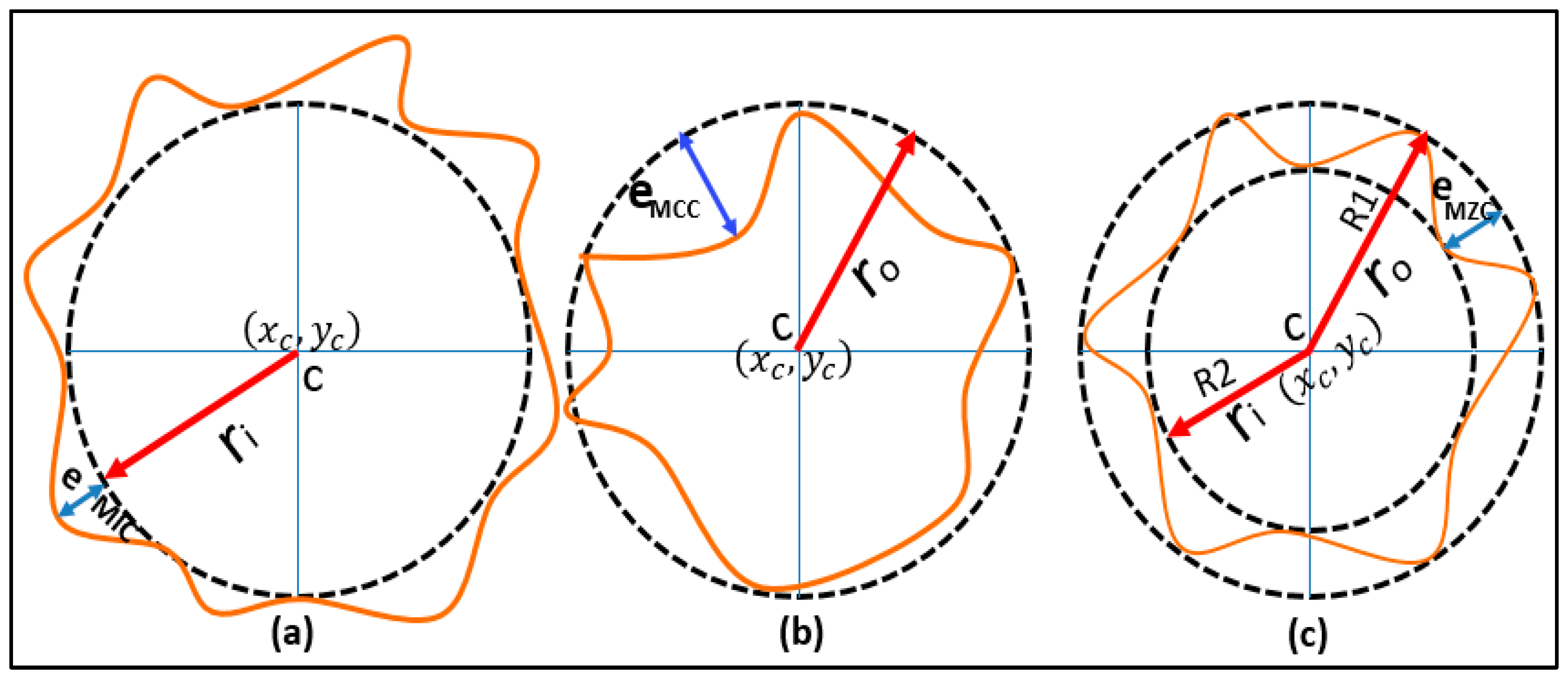
2.1. The Minimum Zone Circles
3. Materials and Methodology
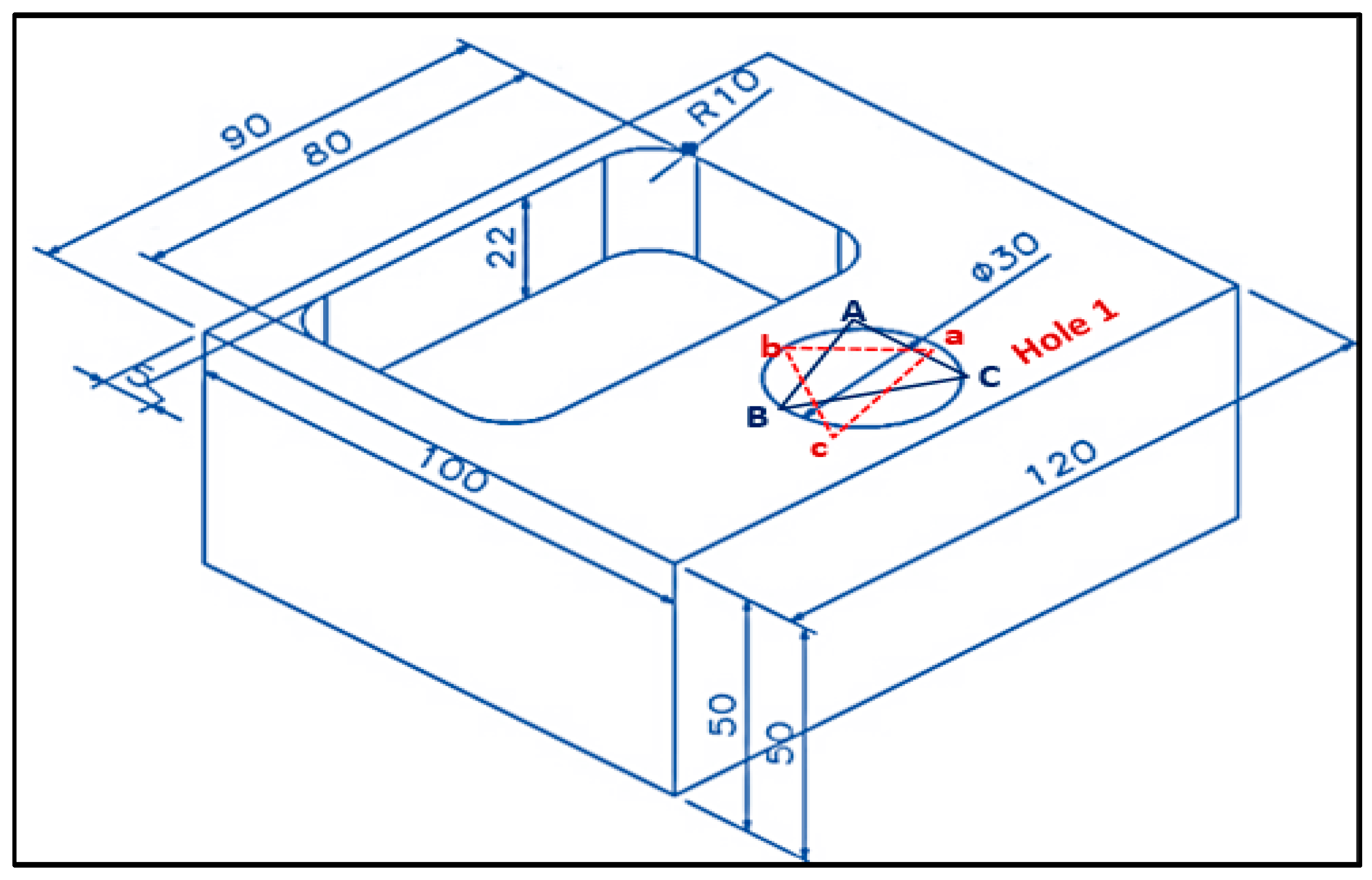
3.1. Materials
3.2. The Experimental Setup and Procedure
Case Study
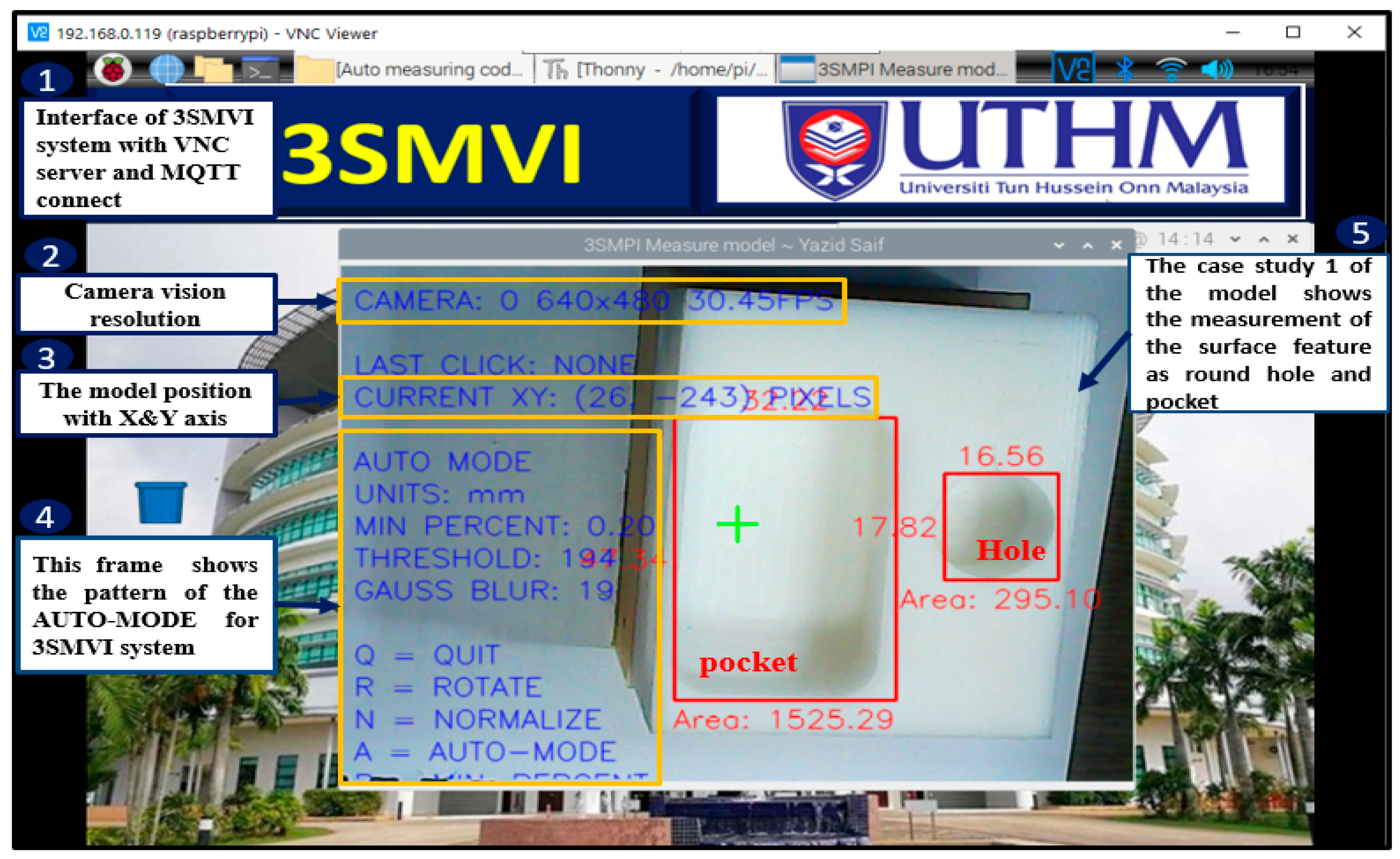
4. The Development of 3SMVI Software and Integration
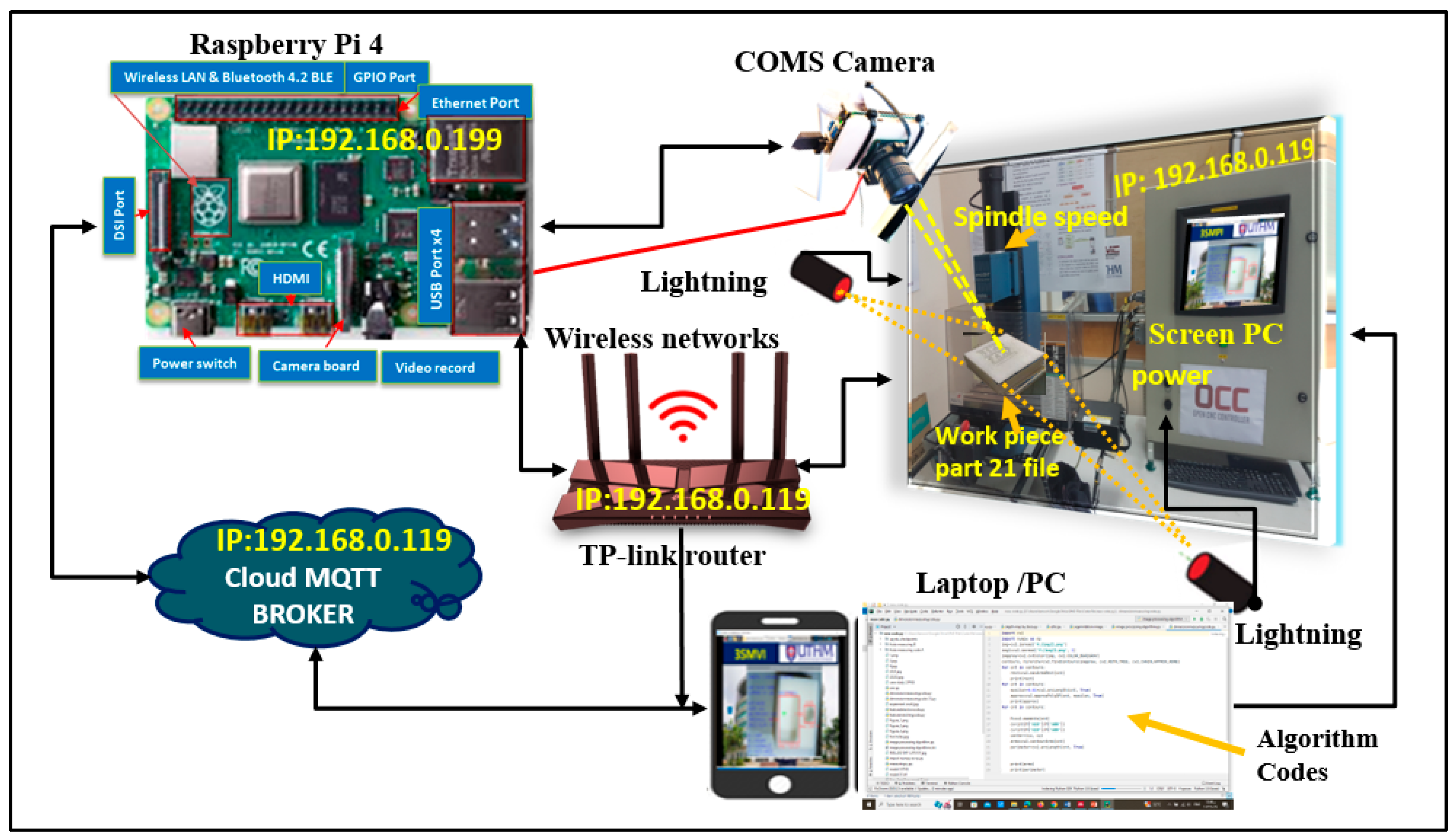
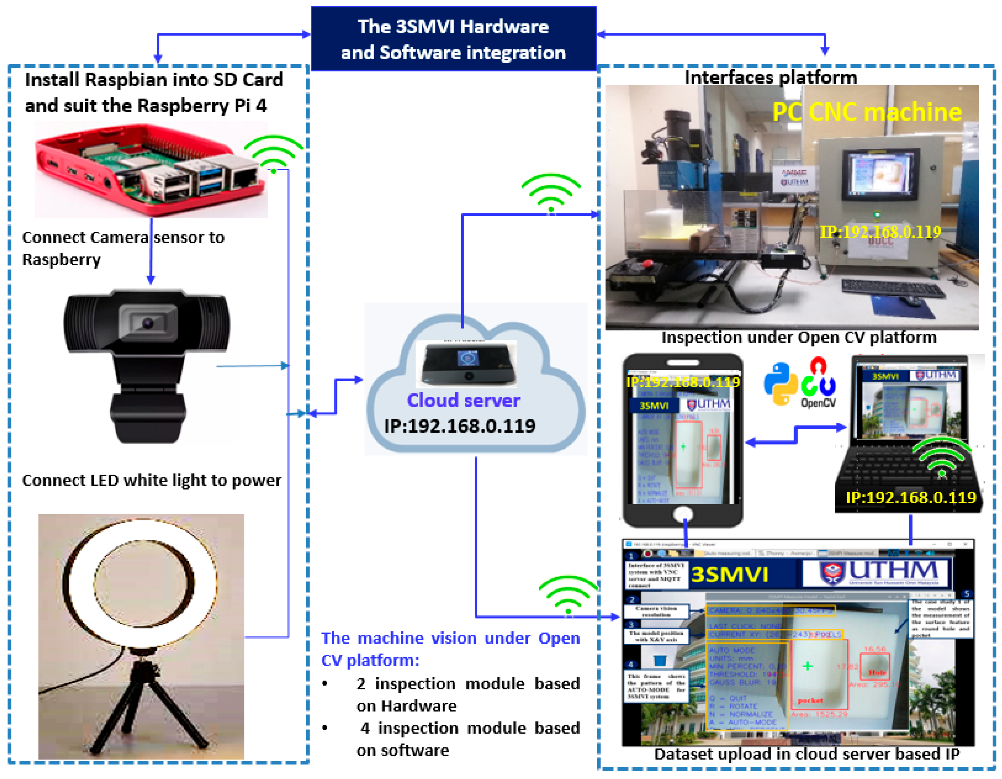
4.1. The 3SMVI Hardware and Software Integration
4.2. Software Utilization and Algorithms
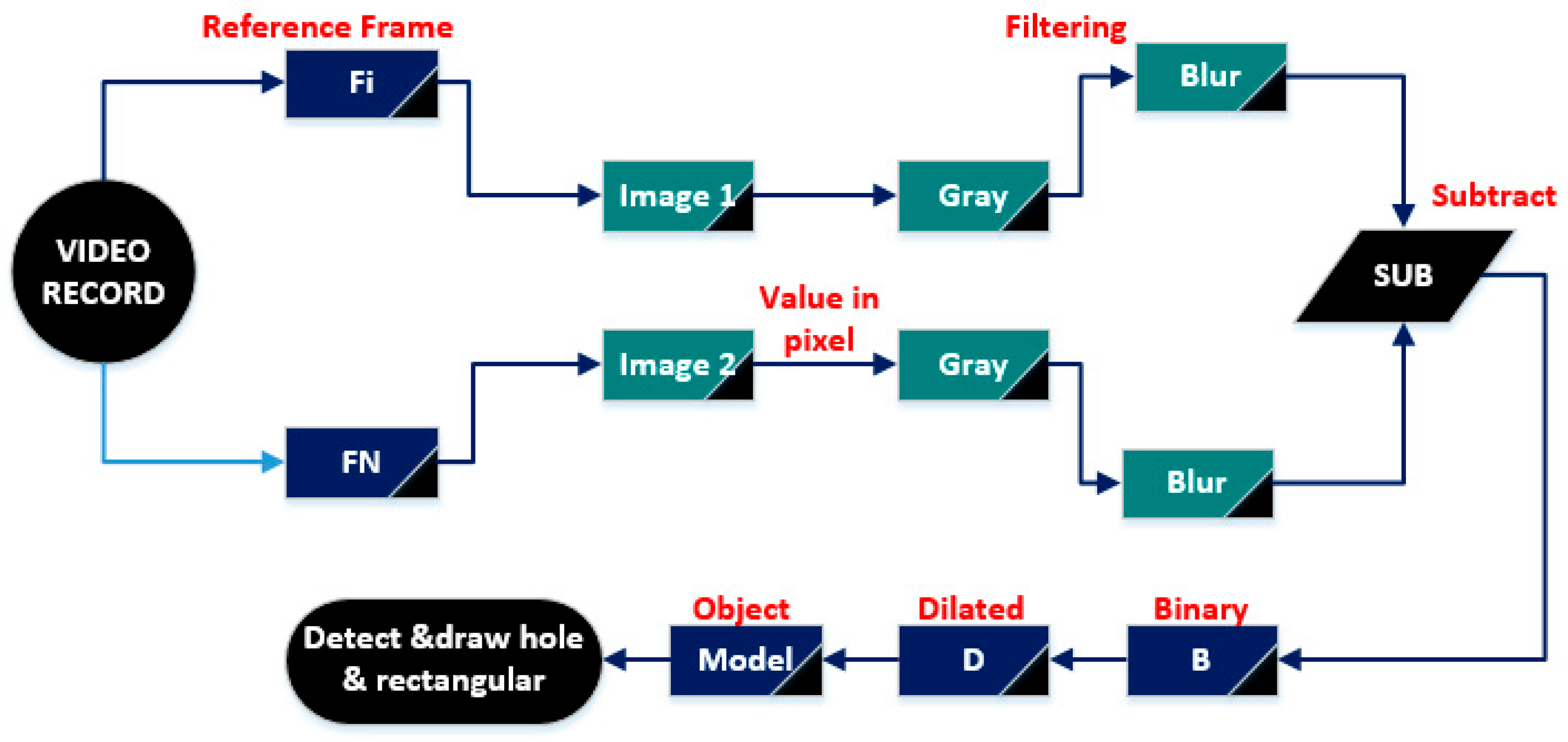
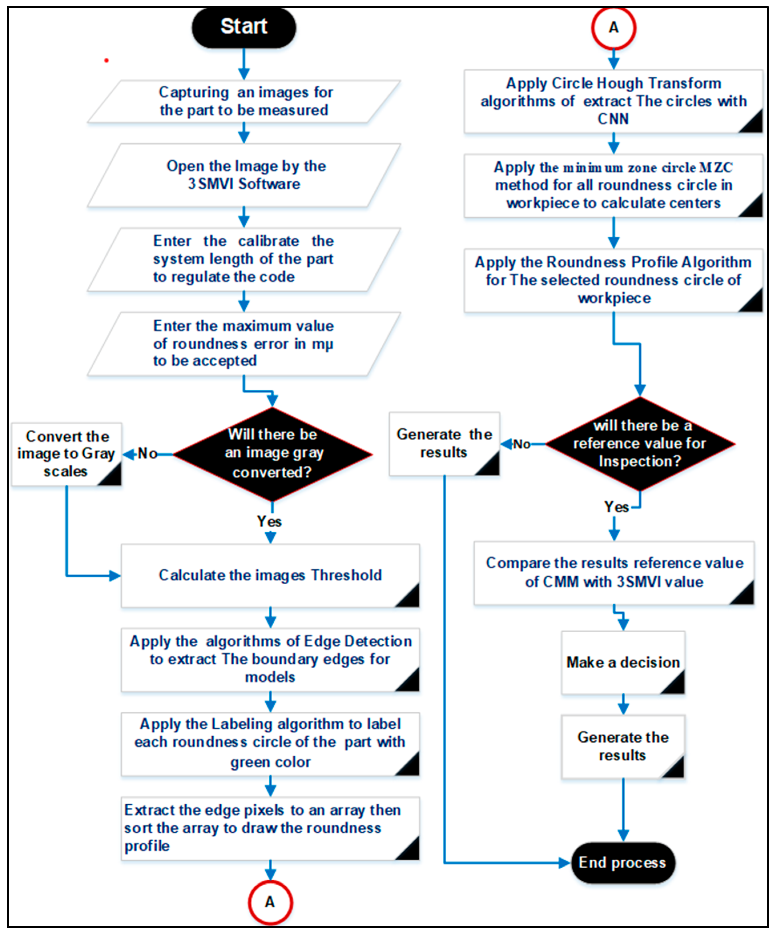
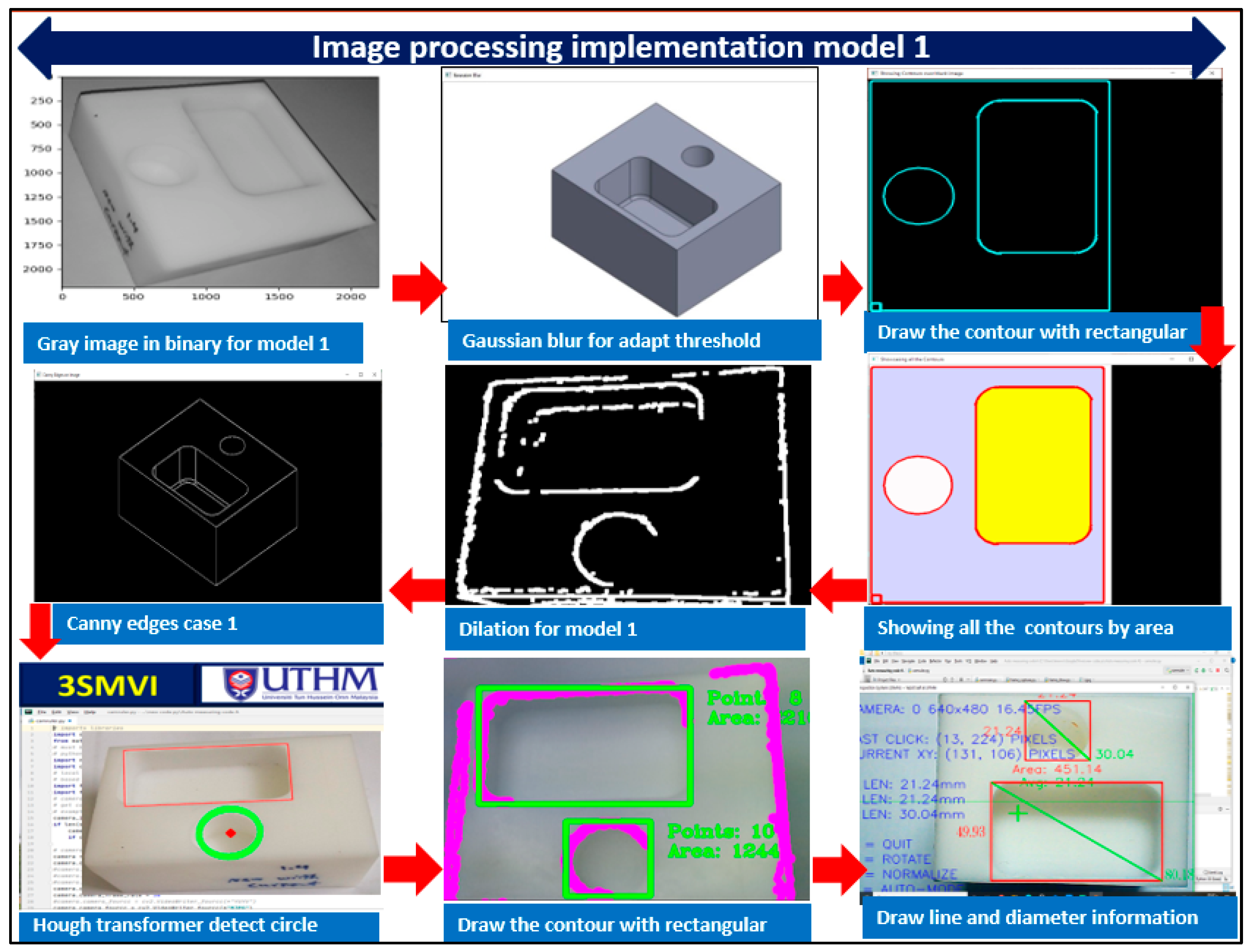
4.3. Image Analysis and Segmentation
4.4. An Algorithm for Detecting Edges
Objects or Models Detection
4.5. Data Acquisition
4.6. The Algorithm for Edge Labelling
- The edge-pixel image is encoded using the run-length algorithm;
- After scanning the runs, each run is given a preliminary label. The label equivalent is then entered into a local equivalent table;
- The classes that are resolved have equivalence;
- Finally, based on the resolved equivalence classes, the runs are given labels.
4.7. The Error Algorithm for Roundness Holes
- The labeled image is scanned from left to right and top to bottom. During this process, the coordinates of the edge pixels of a selected part (color) are extracted and stored in an array known as Edge Pixels;
- The minimum zone method is then applied to the pixels in the Edge Pixels array to determine the center and radius of the minimum zone circle;
- The center of the minimum zone circle is calculated, and the distances between this center and all pixels in the Edge Pixels array are computed. The minimum and maximum distances are identified as .
5. System Calibration
- The user provides the 3SMVI platform with the actual diameter (in millimeters) of the object being measured. If the object is comprised of multiple circular parts, the outer part’s size (maximum diameter) should be utilized.
- The software searches for the two edge pixels on the outer contour with the minimum and maximum x coordinates to determine the maximum diameter of the captured image in the x direction (Dmaxx) using the formulawhere are the maximum and minimum x coordinates of the edge pixels of the outer contour, respectively.
- The calibration factor in the x direction is calculated as follows:
- In the same manner, the calibration process also involves determining the calibration factor in the y direction ) by identifying the two pixels with the minimum and maximum y coordinates, which can be obtained by using the formula
- After calculating , all coordinates of the edge pixels are multiplied by these calibration factors.
- The primary roundness error is then calculated using the least squares circle technique on the edge pixels.
- Furthermore, using a formula derived from Excel, the fixed error in pixels is determined based on the user-provided value of the smoothing factor .
- The fixed error is then calibrated and expressed in millimeters () using the following equation:
- The final roundness error is calculated as follows:
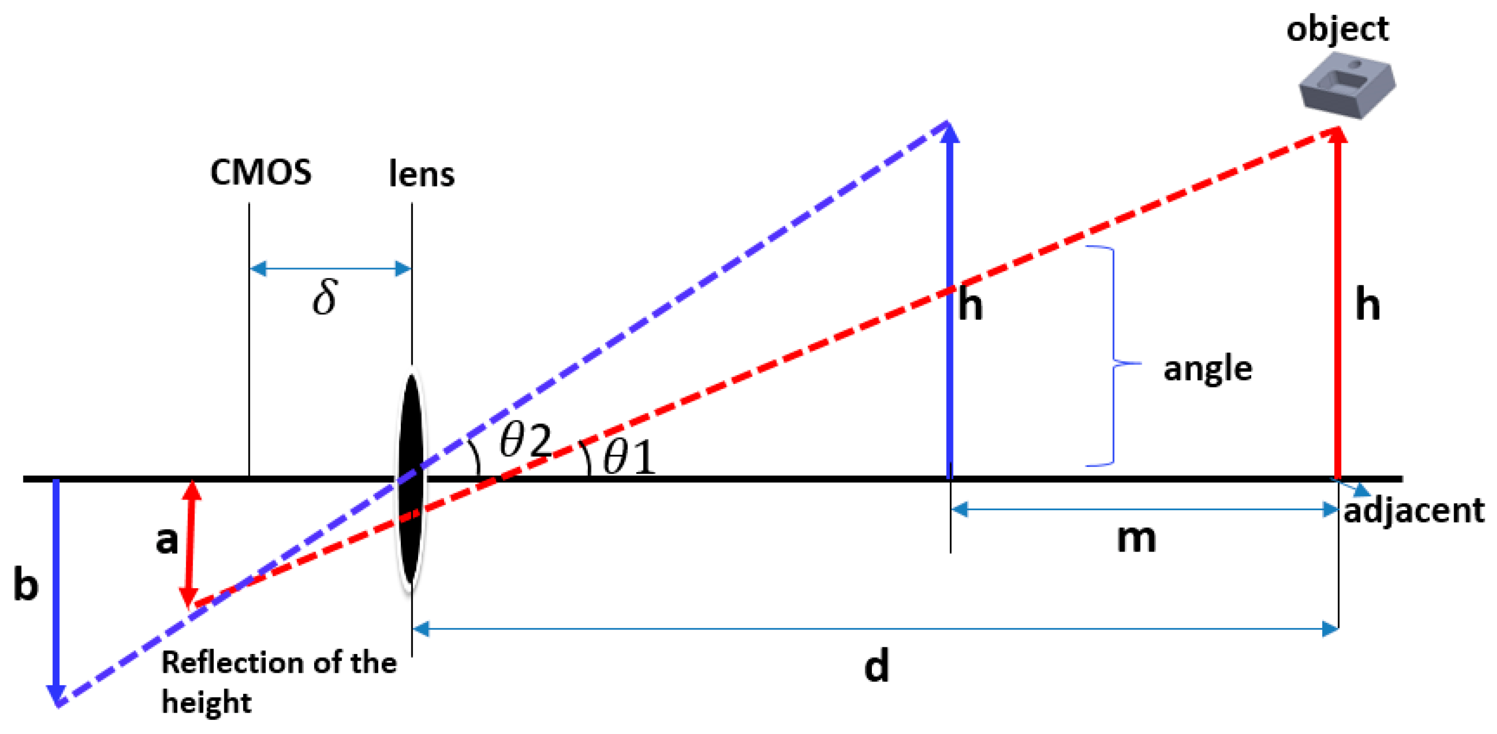
Camera-to-Workpiece Distance Estimation
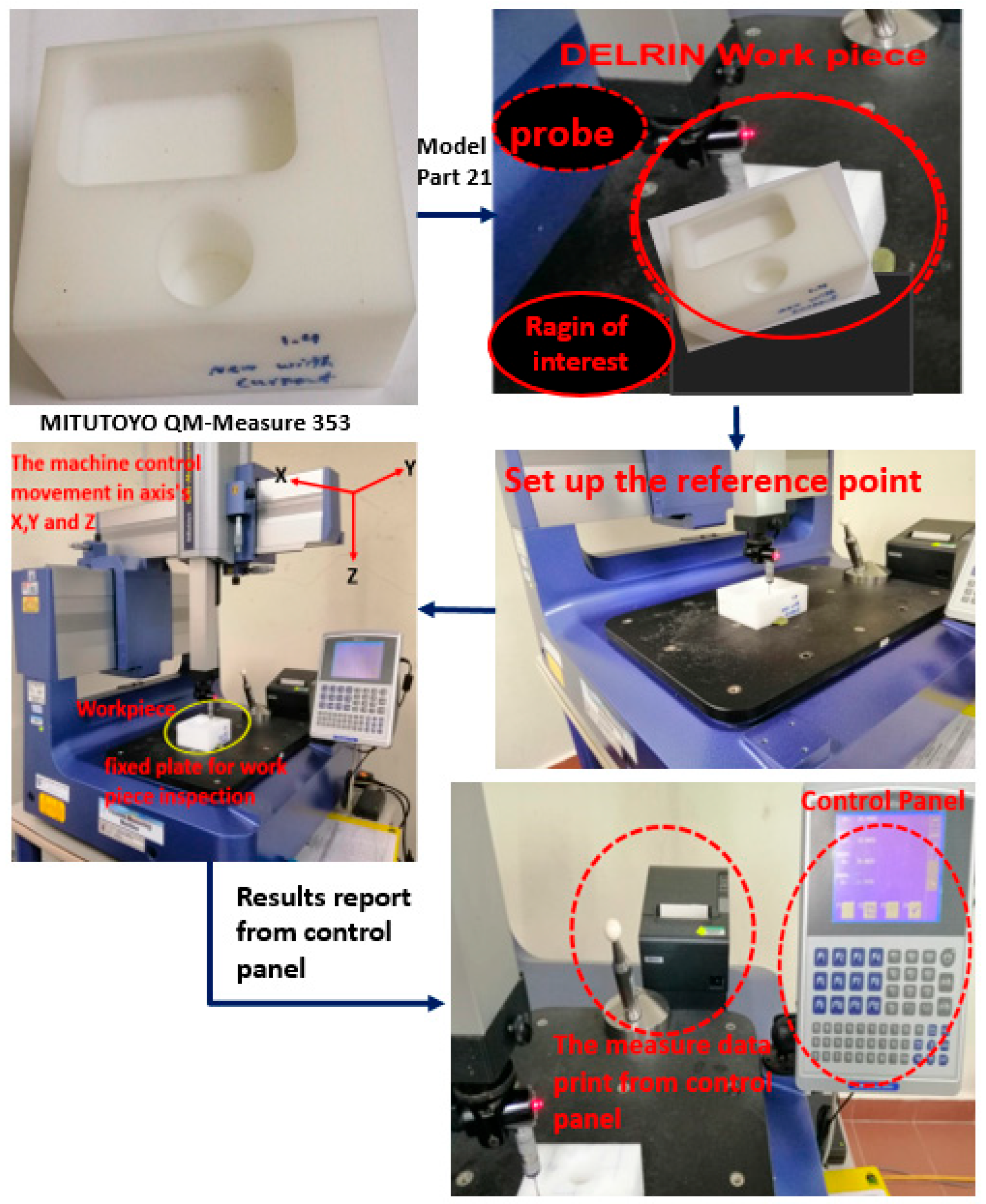
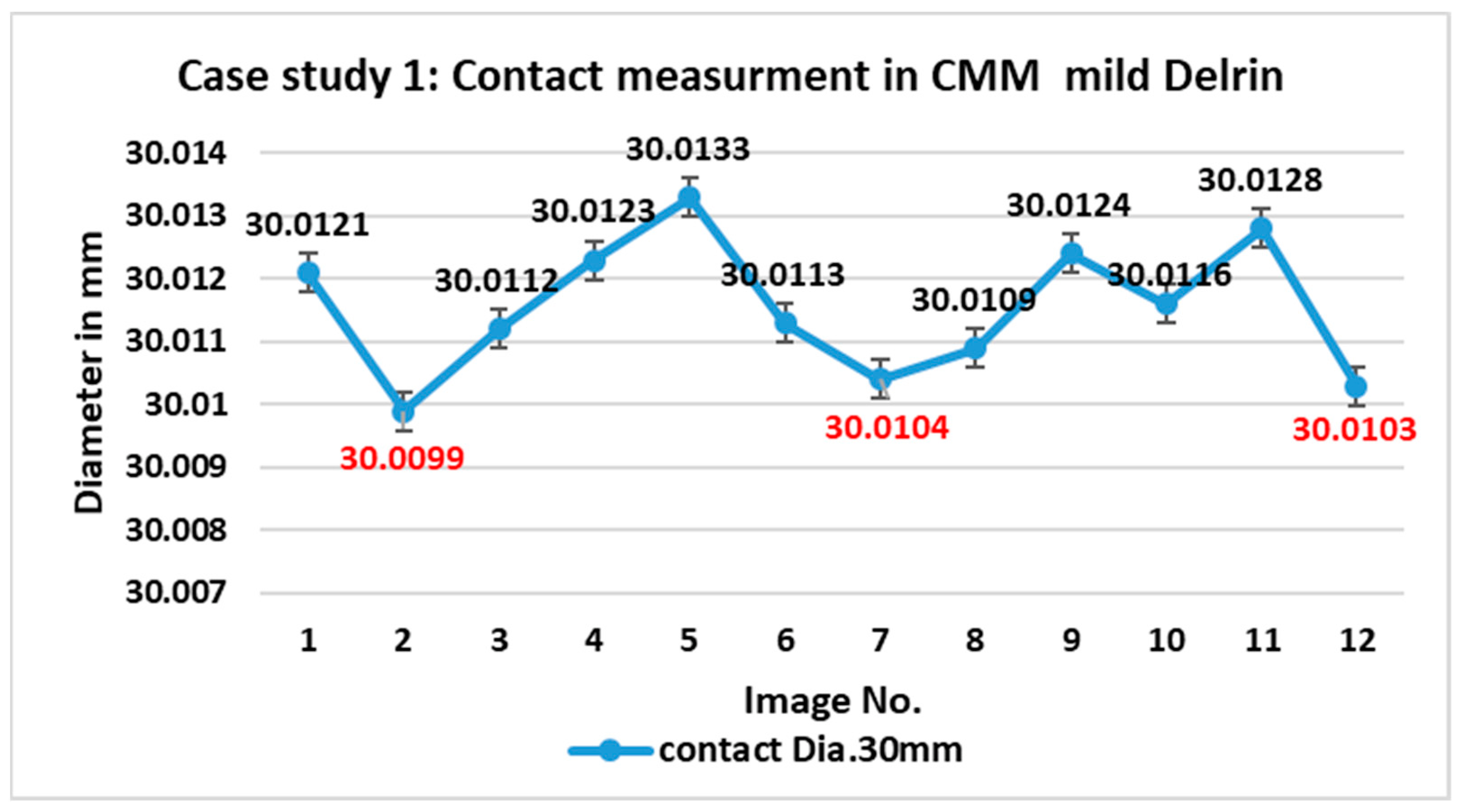
6. CMM Inspection of Contact Measurement
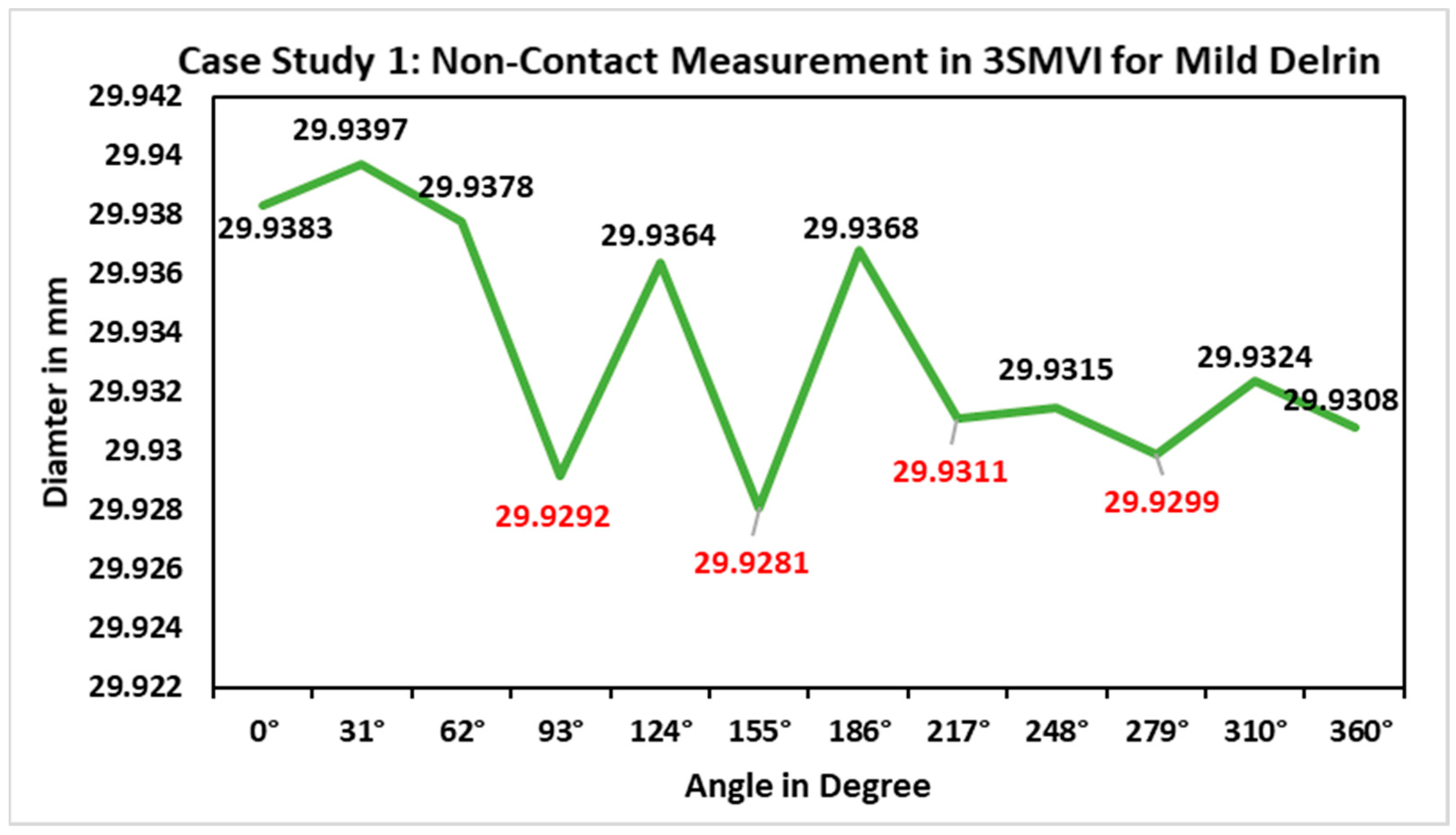
7. Result and Discussion
8. Conclusions and Future Research
Supplementary Materials
Author Contributions
Funding
Institutional Review Board Statement
Informed Consent Statement
Data Availability Statement
Conflicts of Interest
Abbreviations
| ASME | American Society of Mechanical Engineers |
| ACO | Colony Optimization |
| CNC | Computer Numerical Control |
| CMM | Coordinate measuring machine |
| C | Center of this circle |
| CMOS | Complementary metal–oxide–semiconductor |
| EO | Engineering Ontology |
| eMZC | Error-based Minimum Zone radial circles |
| CLIM | Closed-loop inspection manufacturing |
| CAIP | Computer-aided Inspection Planning |
| FTP | File Transfer Protocol |
| GA | General Assembly Simulation |
| GD&T | Geometric Dimensioning and Tolerance |
| I 4.0 | The Fourth Industrial Revolution |
| IoT | Internet of Things |
| WSET | Wire spark erosion machining |
| ISO | International Standard Organization |
| LED | Light-emitting Diodes |
| MQTT | Message Queuing Telemetry Transport |
| MZC | Minimum Zone for Radial Circles |
| MTD | Metrology for the Digitalization |
| Open CV | Open Computer Vision |
| OLP | Offline Programming System |
| OOR | Out-of-the-Round |
| QM | Quality MITUTOYO Measure |
| RGB | Three channels of color: Red, Green, and Blue |
| Ri | Radius inner |
| RU | Upper radius |
| RL | Lower radius |
| STEP-NC | The Standard for the Exchange of Product Model Data for Numerical Control |
| VNC | Visual network center |
| 3SMVI | Smart System based on interpreted STEP-NC for Machine Vision Inspection |
| 3D | Three-dimension model |
References
- Stojadinovic, S.M.; Majstorovic, V.D.; Durakbasa, N.M. Toward a cyber-physical manufacturing metrology model for industry 4.0. Artif. Intell. Eng. Des. Anal. Manuf. 2020, 35, 20–36. [Google Scholar] [CrossRef]
- Ahmad, M.I.; Yusof, Y.; Daud, E.; Latiff, K.; Kadir, A.Z.A.; Saif, Y. Machine monitoring system: A decade in review. Int. J. Adv. Manuf. Technol. 2020, 108, 3645–3659. [Google Scholar] [CrossRef]
- Ashima, R.; Haleem, A.; Bahl, S.; Javaid, M.; Mahla, S.K.; Singh, S. Automation and manufacturing of smart materials in additive manufacturing technologies using Internet of Things towards the adoption of industry 4.0. Mater. Today Proc. 2021, 45, 5081–5088. [Google Scholar] [CrossRef]
- Nate, K.; Tentzeris, M.M. A novel 3-D printed loop antenna using flexible NinjaFlex material for wearable and IoT applications. In Proceedings of the 2015 IEEE 24th Electrical Performance of Electronic Packaging and Systems (EPEPS), San Jose, CA, USA, 25–28 October 2015; pp. 171–174. [Google Scholar] [CrossRef]
- Qin, W.; Chen, S.; Peng, M. Recent advances in Industrial Internet: Insights and challenges. Digit. Commun. Netw. 2020, 6, 1–13. [Google Scholar] [CrossRef]
- Benbarrad, T.; Salhaoui, M.; Kenitar, S.B.; Arioua, M. Intelligent Machine Vision Model for Defective Product Inspection Based on Machine Learning. J. Sens. Actuator Netw. 2021, 10, 7. [Google Scholar] [CrossRef]
- Pan, Y.; White, J.; Schmidt, D.C.; Elhabashy, A.; Sturm, L.; Camelio, J.; Williams, C. Taxonomies for Reasoning About Cyber-physical Attacks in IoT-based Manufacturing Systems. Int. J. Interact. Multimedia Artif. Intell. 2017, 4, 45. [Google Scholar] [CrossRef]
- Wen, X.; Xia, Q.; Zhao, Y. An effective genetic algorithm for circularity error unified evaluation. Int. J. Mach. Tools Manuf. 2006, 46, 1770–1777. [Google Scholar] [CrossRef]
- Renzi, C.; Ceruti, A.; Leali, F. Integrated geometrical and dimensional tolerances stack-up analysis for the design of mechanical assemblies: An application on marine engineering. Comput.-Aided. Des. Appl. 2018, 15, 631–642. [Google Scholar] [CrossRef]
- Guu, S.M.; Tsai, D.M. Measurement of roundness: A nonlinear approach. Proc. Natl. Sci. Counc. Repub. China Part A Phys. Sci. Eng. 1999, 23, 348–352. [Google Scholar]
- Mohamed, A.; Esa, A.H.; Ayub, M.A. Roundness measurement of cylindrical part by machine vision. In Proceedings of the International Conference on Electrical, Control and Computer Engineering 2011 (InECCE), Kuantan, Malaysia, 21–22 June 2011; pp. 486–490. [Google Scholar] [CrossRef]
- Ayub, M.A.; Mohamed, A.B.; Esa, A.H. In-line Inspection of Roundness Using Machine Vision. Procedia Technol. 2014, 15, 807–816. [Google Scholar] [CrossRef]
- Gadelmawla, E.; Khalifa, W.; Elewa, I. Measurement and Inspection of Roundness Using Computer Vision. MEJ Mansoura Eng. J. 2008, 33, 20–32. [Google Scholar] [CrossRef]
- Ali, S.H.R.; Mohamd, O.M. Dimensional and Geometrical Form Accuracy of Circular Pockets Manufactured for Aluminum, Copper and Steel Materials on CNC Milling Machine Using CMM. Int. J. Eng. Res. Afr. 2015, 17, 64–73. [Google Scholar] [CrossRef]
- Gapinski, B.; Kołodziej, A. Measurement of diameter and roundness deviation for circle with incomplete contour. In Proceedings of the 11th International Symposium on Measurement and Quality Control 2013, Cracow-Kielce, Poland, 11–13 September 2013; pp. 142–145. [Google Scholar]
- Janusiewicz, A.; Adamczak, S.; Makieła, W.; Stpień, K. Determining the theoretical method error during an on-machine roundness measurement. Meas. J. Int. Meas. Confed. 2011, 44, 1761–1767. [Google Scholar] [CrossRef]
- Lei, X.; Song, H.; Xue, Y.; Li, J.; Zhou, J.; Duan, M. Method for cylindricity error evaluation using Geometry Optimization Searching Algorithm. Meas. J. Int. Meas. Confed. 2011, 44, 1556–1563. [Google Scholar] [CrossRef]
- Mears, L.; Roth, J.T.; Djurdjanovic, D.; Yang, X.; Kurfess, T. Quality and Inspection of Machining Operations: CMM Integration to the Machine Tool. J. Manuf. Sci. Eng. 2009, 131, 051006. [Google Scholar] [CrossRef]
- Stojadinovic, S.M.; Majstorovic, V.D.; Durakbasa, N.M.; Sibalija, T.V. Towards an intelligent approach for CMM inspection planning of prismatic parts. Meas. J. Int. Meas. Confed. 2016, 92, 326–339. [Google Scholar] [CrossRef]
- Gadelmawla, E.S. Computer Aided Measurement software for roundness evaluation from the coordinate measurement data. In Proceedings of the Ninth Cairo University International Conference on Mechanical Design and Production (MDP-9), Cairo, Egypt, 8–10 January 2008; pp. 270–285. [Google Scholar]
- Hong, R.; Xiang, C.; Liu, H.; Glowacz, A.; Pan, W. Visualizing the Knowledge Structure and Research Evolution of Infrared Detection Technology Studies. Information 2019, 10, 227. [Google Scholar] [CrossRef]
- Xu, P.; Guan, C.; Zhang, H.; Li, G.; Zhao, D.; Ross, R.J.; Shen, Y. Application of Nondestructive Testing Technologies in Preserving Historic Trees and Ancient Timber Structures in China. Forests 2021, 12, 318. [Google Scholar] [CrossRef]
- Yang, J.; Li, S.; Wang, Z.; Dong, H.; Wang, J.; Tang, S. Using deep learning to detect defects in manufacturing: A comprehensive survey and current challenges. Materials 2020, 13, 5755. [Google Scholar] [CrossRef]
- de Araujo, P.R.M.; Lins, R.G. Computer vision system for workpiece referencing in three-axis machining centers. Int. J. Adv. Manuf. Technol. 2020, 106, 2007–2020. [Google Scholar] [CrossRef]
- de Araujo, P.R.M.; Lins, R.G. Cloud-based approach for automatic CNC workpiece origin localization based on image analysis. Robot. Comput. Manuf. 2021, 68, 102090. [Google Scholar] [CrossRef]
- Kumar, B.M.; Ratnam, M.M. Machine vision method for non-contact measurement of surface roughness of a rotating workpiece. Sens. Rev. 2015, 35, 10–19. [Google Scholar] [CrossRef]
- Jones, J.M.; Foster, W.; Twomey, C.R.; Burdge, J.; Ahmed, O.M.; Pereira, T.D.; A Wojick, J.; Corder, G.; Plotkin, J.B.; Abdus-Saboor, I. A machine-vision approach for automated pain measurement at millisecond timescales. eLife 2020, 9, 1–22. [Google Scholar] [CrossRef] [PubMed]
- McCarthy, C.L.; Hancock, N.H.; Raine, S.R. Applied machine vision of plants: A review with implications for field deployment in automated farming operations. Intell. Serv. Robot. 2010, 3, 209–217. [Google Scholar] [CrossRef]
- Di Leo, G.; Liguori, C.; Pietrosanto, A.; Sommella, P. A vision system for the online quality monitoring of industrial manufacturing. Opt. Lasers Eng. 2016, 89, 162–168. [Google Scholar] [CrossRef]
- Fernández-Robles, L.; Azzopardi, G.; Alegre, E.; Petkov, N. Machine-vision-based identification of broken inserts in edge profile milling heads. Robot. Comput. Manuf. 2017, 44, 276–283. [Google Scholar] [CrossRef]
- Saif, Y.; Yusof, Y.; Latif, K.; Kadir, A.Z.A.; Ahmed, M.L. Systematic review of STEP-NC-based inspection. Int. J. Adv. Manuf. Technol. 2020, 108, 3619–3644. [Google Scholar] [CrossRef]
- Lin, E.-Y.; Tu, C.-T.; Lien, J.-J.J. Nut Geometry Inspection Using Improved Hough Line and Circle Methods. Sensors 2023, 23, 3961. [Google Scholar] [CrossRef]
- Meadows, J.D. Measurement of Geometric Tolerances in Manufacturing; Marcell Dekker, Inc.: New York, NY, USA, 1998; Volume 1998. [Google Scholar]
- García-Martínez, E.; García-González, N.; Manjabacas, M.C.; Miguel, V. Validation of a Manual Methodology for Measuring Roundness and Cylindricity Tolerances. Appl. Sci. 2023, 13, 9702. [Google Scholar] [CrossRef]
- Zhao, Z.; Xi, J.; Zhao, X.; Zhang, G.; Shang, M. Evaluation of the Calculated Sizes Based on the Neural Network Regression. Math. Probl. Eng. 2018, 2018, 4078456. [Google Scholar] [CrossRef]
- Cioboata, D.; Dontu, O.; Besnea, D.; Ciobanu, R.; Soare, A. Mecatronic equipment for bearing ring surface inspection. Rom. Rev. Precis. Mech. Opt. Mechatron. 2015, 2015, 262–266. [Google Scholar]
- Du, C.L.; Luo, C.X.; Han, Z.T.; Zhu, Y.S. Applying particle swarm optimization algorithm to roundness error evaluation based on minimum zone circle. Meas. J. Int. Meas. Confed. 2014, 52, 12–21. [Google Scholar] [CrossRef]
- Jbira, I.; Tahan, A.; Mahjoub, M.A.; Louhichi, B. Evaluation of the Algorithmic Error of New Specification Tools for an ISO 14405-1:2016 Size. In International Design Engineering Technical Conferences and Computers and Information in Engineering Conference, Quebec City, QC, Canada, 26–29 August 2018; American Society of Mechanical Engineers: New York, NY, USA, 2018. [Google Scholar] [CrossRef]
- Gosavi, A.; Cudney, E.A. Form Errors in Precision Metrology: A Survey of Measurement Techniques. Qual. Eng. 2012, 24, 369–380. [Google Scholar] [CrossRef]
- Kshaurad, K.; Kiran, M.; Shanmuganatan, S. Minimum zone tolerance algorithm to detect roundness error for machined rods using vision system. Mater. Today Proc. 2021, 46, 5997–6003. [Google Scholar] [CrossRef]
- Sui, W.; Zhang, D. Four Methods for Roundness Evaluation. Phys. Procedia 2012, 24, 2159–2164. [Google Scholar] [CrossRef]
- Rhinithaa, P.T.; Selvakumar, P.; Sudhakaran, N.; Anirudh, V.; Lawrence, K.D.; Mathew, J. Comparative study of roundness evaluation algorithms for coordinate measurement and form data. Precis. Eng. 2018, 51, 458–467. [Google Scholar] [CrossRef]
- Nurunnabi, A.; Sadahiro, Y.; Lindenbergh, R. Robust cylinder fitting in three-dimensional point cloud data. Int. Arch. Photogramm. Remote Sens. Spat. Inf. Sci.-ISPRS Arch. 2017, 42, 63–70. [Google Scholar] [CrossRef]
- Nurunnabi, A.; Sadahiro, Y.; Laefer, D.F. Robust statistical approaches for circle fitting in laser scanning three-dimensional point cloud data. Pattern Recognit. 2018, 81, 417–431. [Google Scholar] [CrossRef]
- Guo, J.; Yang, J. An iterative procedure for robust circle fitting. Commun. Stat.-Simul. Comput. 2019, 48, 1872–1879. [Google Scholar] [CrossRef]
- Liu, Y.; Zhu, L.S.; Xiong, Q.J. Development of Quality Detecting System for Micro Holes by ECM Based on Machine Vision Technology. Appl. Mech. Mater. 2013, 397–400, 1482–1485. [Google Scholar] [CrossRef]
- Chaubey, S.K.; Gupta, K. An experimental study on out-of-roundness and material erosion rate during wire spark erosion turning of titanium cylindrical bars. J. Mater. Res. Technol. 2023, 24, 7539–7551. [Google Scholar] [CrossRef]
- Srinivasu, D.S.; Venkaiah, N. Minimum zone evaluation of roundness using hybrid global search approach. Int. J. Adv. Manuf. Technol. 2017, 92, 2743–2754. [Google Scholar] [CrossRef]
- Liu, Q.M.; Li, X. Machine Vision Detection on Circle with Non-Uniform Points. Appl. Mech. Mater. 2014, 687–691, 819–822. [Google Scholar] [CrossRef]
- Saif, Y.; Yusof, Y.; Latif, K.; Kadir, A.Z.A.; Ahmed, M.B.L.; Adam, A.; Hatem, N.; Memon, D.A. Roundness Holes’ Measurement for milled workpiece using machine vision inspection system based on IoT structure: A case study. Meas. J. Int. Meas. Confed. 2022, 195, 111072. [Google Scholar] [CrossRef]
- Sun, T.-H. Applying particle swarm optimization algorithm to roundness measurement. Expert Syst. Appl. 2009, 36, 3428–3438. [Google Scholar] [CrossRef]
- Wang, T.; Chen, Y.; Qiao, M.; Snoussi, H. A fast and robust convolutional neural network-based defect detection model in product quality control. Int. J. Adv. Manuf. Technol. 2018, 94, 3465–3471. [Google Scholar] [CrossRef]
- Liao, Z.; Abdelhafeez, A.; Li, H.; Yang, Y.; Diaz, O.G.; Axinte, D. State-of-the-art of surface integrity in machining of metal matrix composites. Int. J. Mach. Tools Manuf. 2019, 143, 63–91. [Google Scholar] [CrossRef]
- AKim, D.-H.; Kim, T.J.Y.; Wang, X.; Kim, M.; Quan, Y.-J.; Oh, J.W.; Min, S.-H.; Kim, H.; Bhandari, B.; Yang, I.; et al. Smart Machining Process Using Machine Learning: A Review and Perspective on Machining Industry. Int. J. Precis. Eng. Manuf.-Green Technol. 2018, 5, 555–568. [Google Scholar] [CrossRef]
- Bulnes, F.G.; Usamentiaga, R.; Garcia, D.F.; Molleda, J. An efficient method for defect detection during the manufacturing of web materials. J. Intell. Manuf. 2016, 27, 431–445. [Google Scholar] [CrossRef]
- Song, K.; Yan, Y. A noise robust method based on completed local binary patterns for hot-rolled steel strip surface defects. Appl. Surf. Sci. 2013, 285, 858–864. [Google Scholar] [CrossRef]
- Zhang, Y.; Shen, H.; Bo, X.; Li, A.; Zhan, Y.; Gu, H. Amultiscale evaluation of the surface integrity in boring trepanning association deep hole drilling. Int. J. Mach. Tools Manuf. 2017, 123, 48–56. [Google Scholar] [CrossRef]
- Rao, X.; Zhang, F.; Lu, Y.; Luo, X.; Chen, F. Surface and subsurface damage of reaction-bonded silicon carbide induced by electrical discharge diamond grinding. Int. J. Mach. Tools Manuf. 2020, 154, 103564. [Google Scholar] [CrossRef]
- Huang, S.-H.; Pan, Y.-C. Automated visual inspection in the semiconductor industry: A survey. Comput. Ind. 2015, 66, 1–10. [Google Scholar] [CrossRef]
- Ravimal, D.; Kim, H.; Koh, D.; Hong, J.H.; Lee, S.-K. Image-Based Inspection Technique of a Machined Metal Surface for an Unmanned Lapping Process. Int. J. Precis. Eng. Manuf. Technol. 2020, 7, 547–557. [Google Scholar] [CrossRef]
- Ren, Z.; Fang, F.; Yan, N.; Wu, Y. State of the Art in Defect Detection Based on Machine Vision. Int. J. Precis. Eng. Manuf.-Green Technol. 2021, 9, 661–691. [Google Scholar] [CrossRef]
- Penumuru, D.P.; Muthuswamy, S.; Karumbu, P. Identification and classification of materials using machine vision and machine learning in the context of industry 4.0. J. Intell. Manuf. 2020, 31, 1229–1241. [Google Scholar] [CrossRef]
- Ali, M.A.H.; Lun, A.K. A cascading fuzzy logic with image processing algorithm–based defect detection for automatic visual inspection of industrial cylindrical object’s surface. Int. J. Adv. Manuf. Technol. 2019, 102, 81–94. [Google Scholar] [CrossRef]
- Badmos, O.; Kopp, A.; Bernthaler, T.; Schneider, G. Image-based defect detection in lithium-ion battery electrode using convolutional neural networks. J. Intell. Manuf. 2020, 31, 885–897. [Google Scholar] [CrossRef]
- Elias, M.Z.; Malamas, N.; Petrakis Euripides, G.M. A survey on industrial vision systems, applications and tools. Image Vis. Comput. 2003, 2, 171–188. [Google Scholar] [CrossRef]
- Saif, Y.; Yusof, Y.; Latif, K.; Kadir, A.Z.A.; Ahmad, M.B.I.; Adam, A.; Hatem, N. Development of a smart system based on STEP-NC for machine vision inspection with IoT environmental. Int. J. Adv. Manuf. Technol. 2021, 118, 4055–4072. [Google Scholar] [CrossRef]


| Machine Characteristics | Parameter | Specification |
|---|---|---|
| Machine Part | Workpiece | Delrin |
| Size | 120 × 100 × 50 mm | |
| Machining | Feed rate | 0.1 mm |
| Spindle speed | 2500 rpm | |
| Depth of cut | 22 mm | |
| One Circle diameter | 30 mm | |
| Cutting speed | 250 m/s | |
| Cutting tool | Material type | High-speed steel |
| Diameter | 0.6 mm | |
| Number of flutes | 2 | |
| Tool type | New tool | |
| Number of axes | Three axes, X, Y, and Z | |
| CMM measurement | Machine type | MITUTOYO QM-353 |
| Resolution | 0.0005 mm (0.00002 in.) | |
| High accuracy | Accuracy of min 0.0017 mm | |
| Versatility | Wide range of probe systems are available | |
| Software | ||
| Open CV | Open Vision Library2011, windows 10 | |
| Python | 3.8.3 | |
| Pycharm editor | IDE used in computer programming for Python | |
| CAD design | CATIA v5, R21 2020 | |
| Operating System | The Raspbian Debian Buster | |
| MQTT protocol | Messaging protocol designed for low-bandwidth |
| Image No. | Angle in Degree | Mild Delrin Dia. 30 mm |
|---|---|---|
| 1 | 0° | 29.9383 |
| 2 | 31° | 29.9397 |
| 3 | 62° | 29.9378 |
| 4 | 93° | 29.9292 |
| 5 | 124° | 29.9364 |
| 6 | 155° | 29.9281 |
| 7 | 186° | 29.9368 |
| 8 | 217° | 29.9311 |
| 9 | 248° | 29.9315 |
| 10 | 279° | 29.9299 |
| 11 | 310° | 29.9324 |
| 12 | 360° | 29.9308 |
| 2.9 µm |
| No. of Point | Points | Mild Delrin Dia. 30 mm |
|---|---|---|
| 3 | A,B,C | 30.0121 |
| 3 | A,C,B | 30.0099 |
| 3 | B,A,C | 30.0112 |
| 3 | B,C,A | 30.0123 |
| 3 | C,A,B | 30.0133 |
| 3 | C,B,A | 30.0113 |
| 3 | a,b,c | 30.0104 |
| 3 | a,c,b | 30.0109 |
| 3 | b,a,c | 30.0124 |
| 3 | b,c,a | 30.0116 |
| 3 | c,a,b | 30.0128 |
| 3 | c,b,a | 30.0103 |
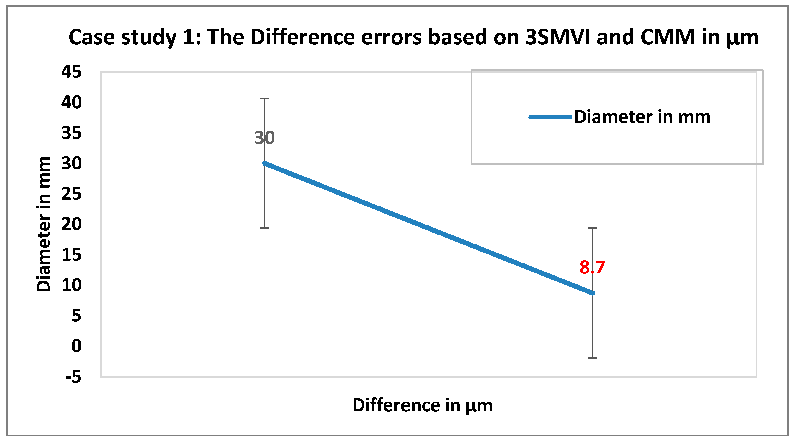
| Diameter in mm | Hole Circle Error from 3SMVI System in µm | Hole Circle Error from CMM in µm | Difference in µm |
|---|---|---|---|
| 30 | 11.6 µm | 2.9 µm | 8.7 |
Disclaimer/Publisher’s Note: The statements, opinions and data contained in all publications are solely those of the individual author(s) and contributor(s) and not of MDPI and/or the editor(s). MDPI and/or the editor(s) disclaim responsibility for any injury to people or property resulting from any ideas, methods, instructions or products referred to in the content. |
© 2023 by the authors. Licensee MDPI, Basel, Switzerland. This article is an open access article distributed under the terms and conditions of the Creative Commons Attribution (CC BY) license (https://creativecommons.org/licenses/by/4.0/).
Share and Cite
Saif, Y.; Rus, A.Z.M.; Yusof, Y.; Ahmed, M.L.; Al-Alimi, S.; Didane, D.H.; Adam, A.; Gu, Y.H.; Al-masni, M.A.; Abdulrab, H.Q.A. Advancements in Roundness Measurement Parts for Industrial Automation Using Internet of Things Architecture-Based Computer Vision and Image Processing Techniques. Appl. Sci. 2023, 13, 11419. https://doi.org/10.3390/app132011419
Saif Y, Rus AZM, Yusof Y, Ahmed ML, Al-Alimi S, Didane DH, Adam A, Gu YH, Al-masni MA, Abdulrab HQA. Advancements in Roundness Measurement Parts for Industrial Automation Using Internet of Things Architecture-Based Computer Vision and Image Processing Techniques. Applied Sciences. 2023; 13(20):11419. https://doi.org/10.3390/app132011419
Chicago/Turabian StyleSaif, Yazid, Anika Zafiah M. Rus, Yusri Yusof, Maznah Lliyas Ahmed, Sami Al-Alimi, Djamal Hissein Didane, Anbia Adam, Yeong Hyeon Gu, Mohammed A. Al-masni, and Hakim Qaid Abdullah Abdulrab. 2023. "Advancements in Roundness Measurement Parts for Industrial Automation Using Internet of Things Architecture-Based Computer Vision and Image Processing Techniques" Applied Sciences 13, no. 20: 11419. https://doi.org/10.3390/app132011419
APA StyleSaif, Y., Rus, A. Z. M., Yusof, Y., Ahmed, M. L., Al-Alimi, S., Didane, D. H., Adam, A., Gu, Y. H., Al-masni, M. A., & Abdulrab, H. Q. A. (2023). Advancements in Roundness Measurement Parts for Industrial Automation Using Internet of Things Architecture-Based Computer Vision and Image Processing Techniques. Applied Sciences, 13(20), 11419. https://doi.org/10.3390/app132011419