
Options on Tooth Profile Modification by Hob Adjustment


Abstract
:Featured Application
Abstract
1. Introduction
2. Methodology
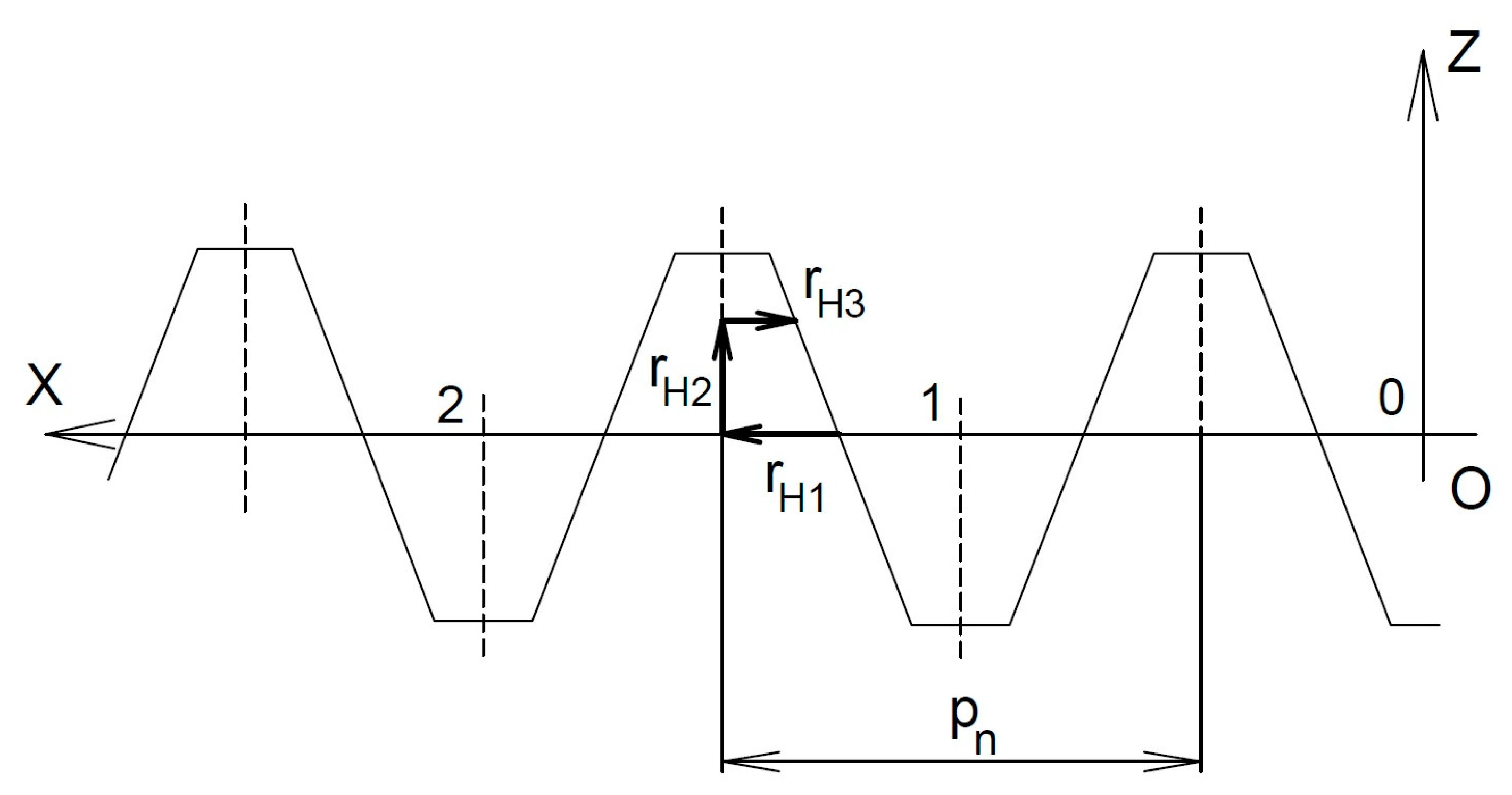
2.1. Position Vector of the Hob Profile
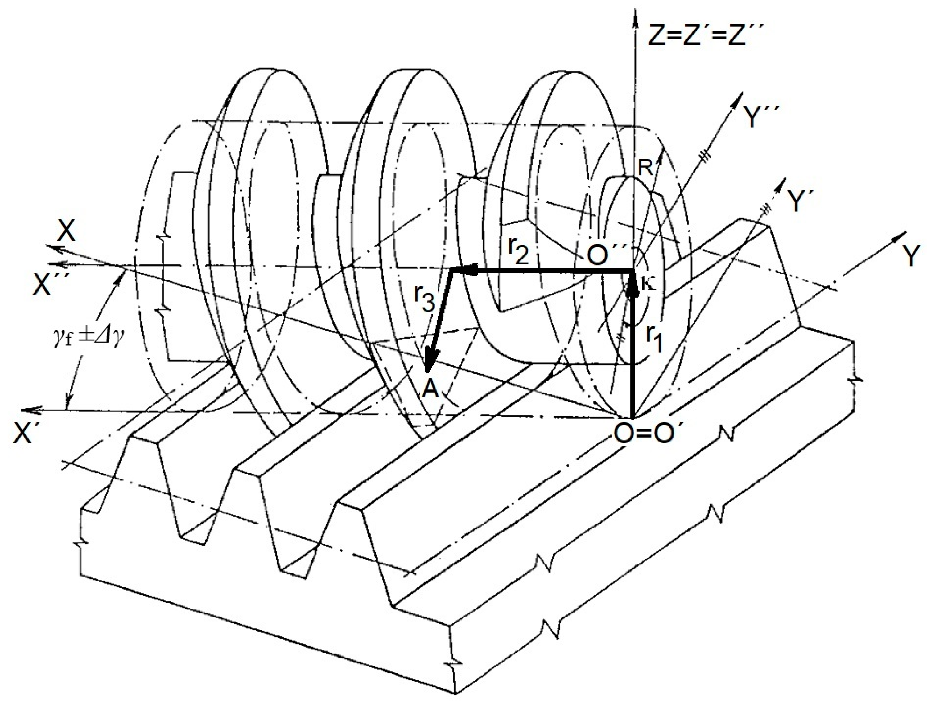
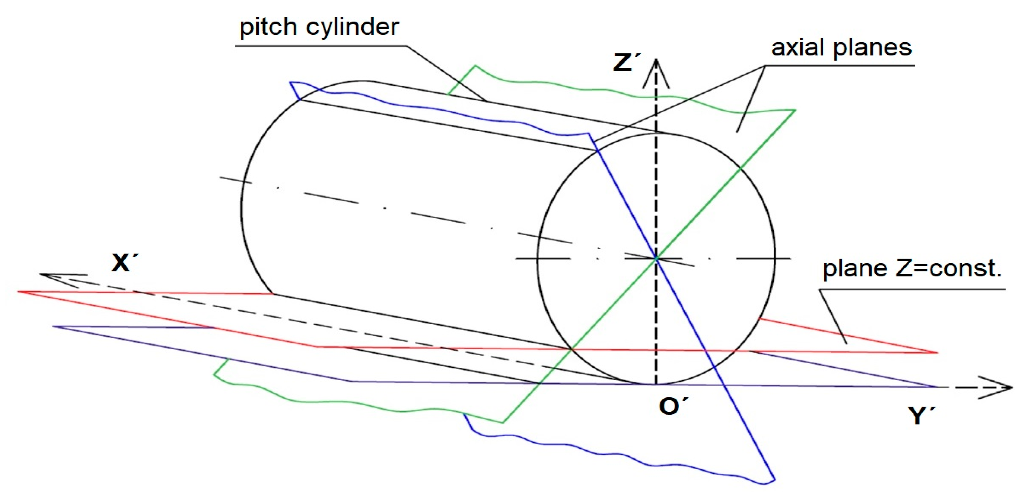
2.2. Position Vector of the Basic Rack Profile
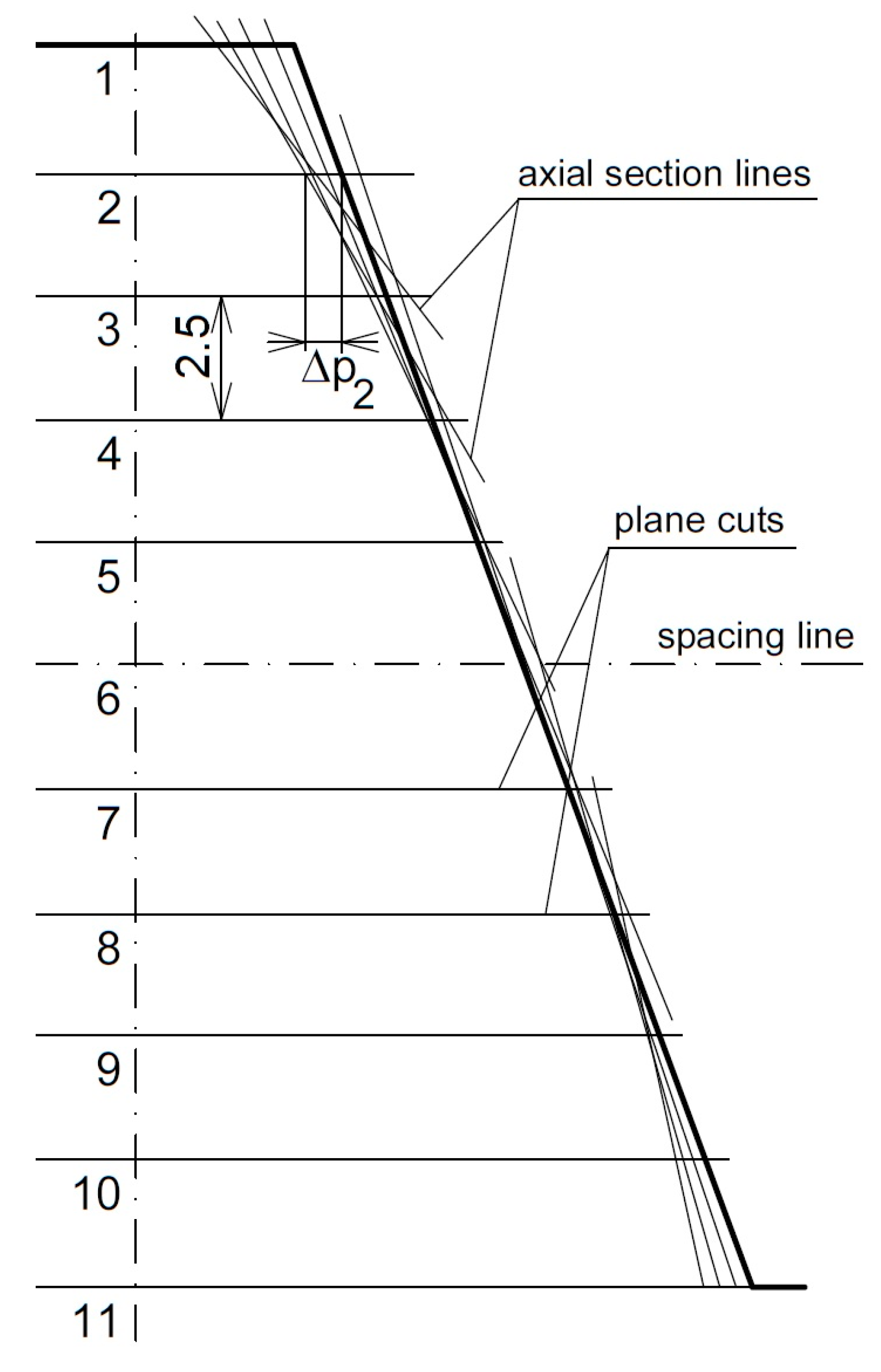
2.3. Method for Determination of the Deviations in the Profiles of the Basic Rack and the Hob
2.4. Method for Determination of the Profile Deviations in the Workpiece Tooth
3. Discussion
4. Conclusions
Author Contributions
Funding
Institutional Review Board Statement
Informed Consent Statement
Data Availability Statement
Conflicts of Interest
Nomenclature
| A (t, n, b) | Coordinate system of the rolling mill profile |
| AH (nH, bH) | Coordinate system of the base ridge profile |
| AK (n, b) | Coordinate system of the tooth profile in the manufactured wheel |
| O (x, y, z) | Fixed coordinate system |
| O′(x′, y′, z′) | Coordinate system turned into it |
| O″(x″, y″, z″) | Coordinate system of the hob |
| Ok (x, y) | Coordinate systems |
| O′k (x′, y′) | Coordinate systems |
| i, j, k, t, n, b | Unit vectors |
| r1, r2, r3 | Components of the position vector |
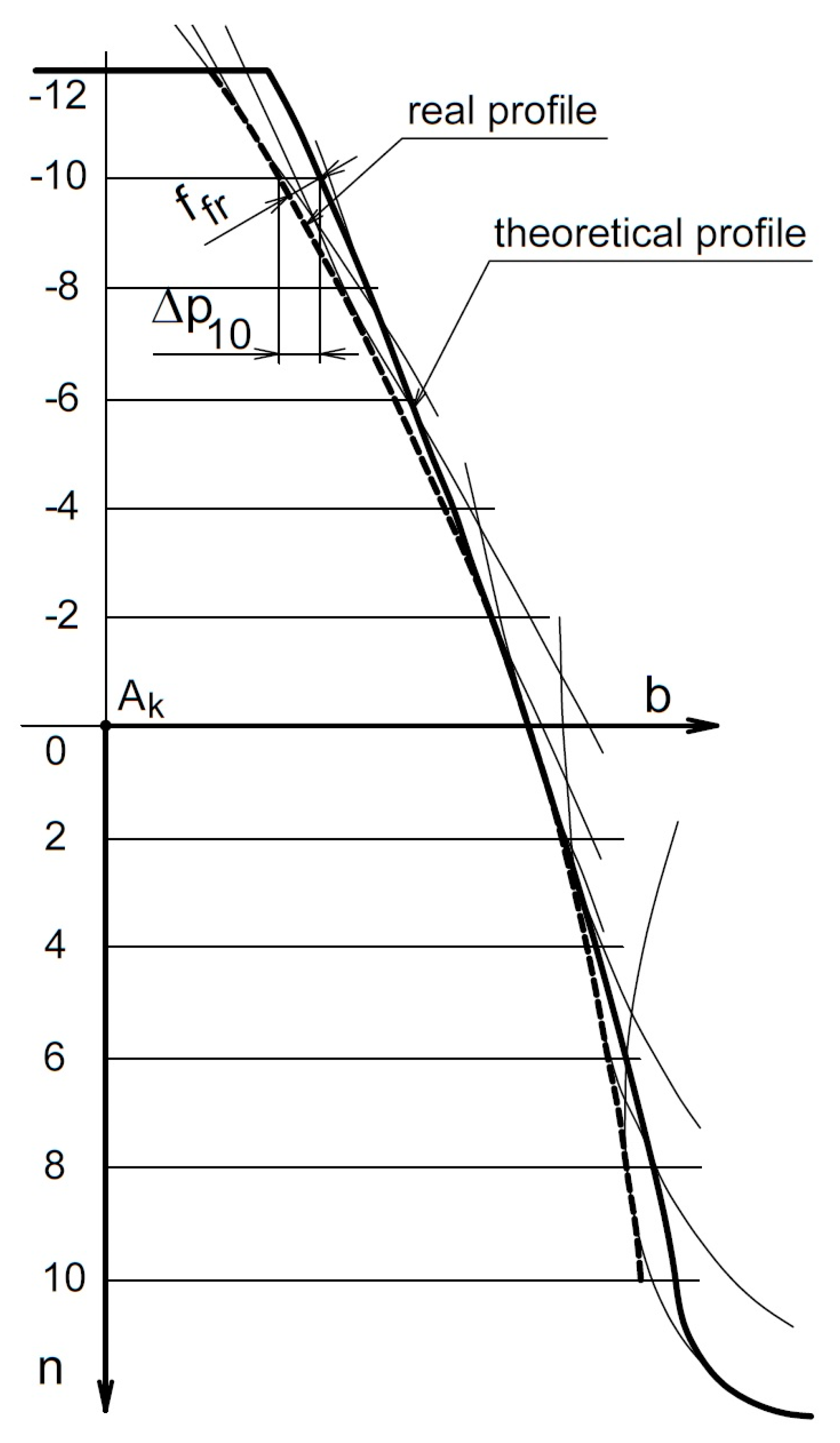
| bteo | Coordinate of the theoretical tooth profile in the manufactured wheel (mm) |
| bsk | Coordinate of the actual tooth profile in the manufactured wheel (mm) |
| hn, hm, hb | Coordinate of the profile point in the basic ridge, or of the rolling mill in the coordinate system AH, AK (mm) |
| x, y, z | Coordinates of the point in the screw plane of the hob |
| rt | Position vector |
| rH | Final vector |
| rs | Final position vector of the basic rack |
| r | Final position vector |
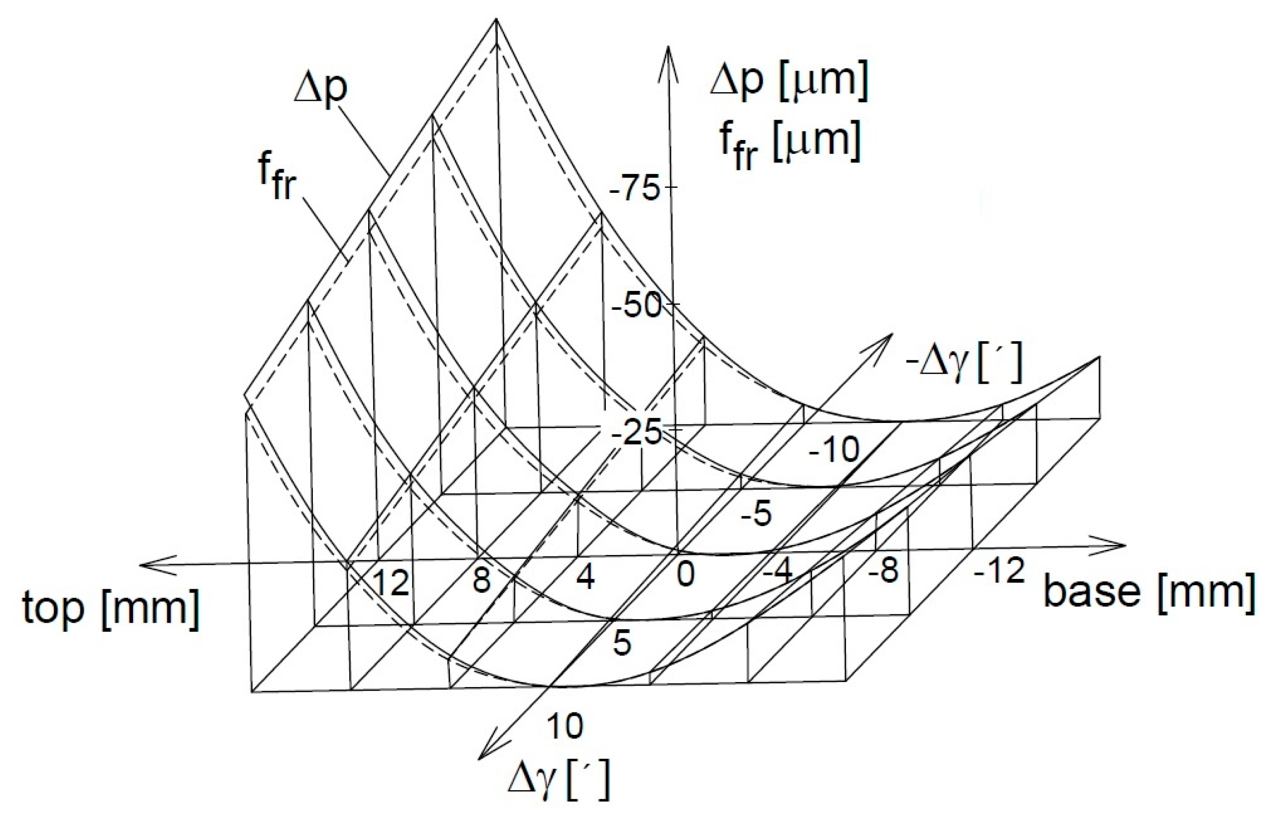
| Δpi | Deviation in the profile of the rolling cutter from the profile of the basic ridge in section i (μm) |
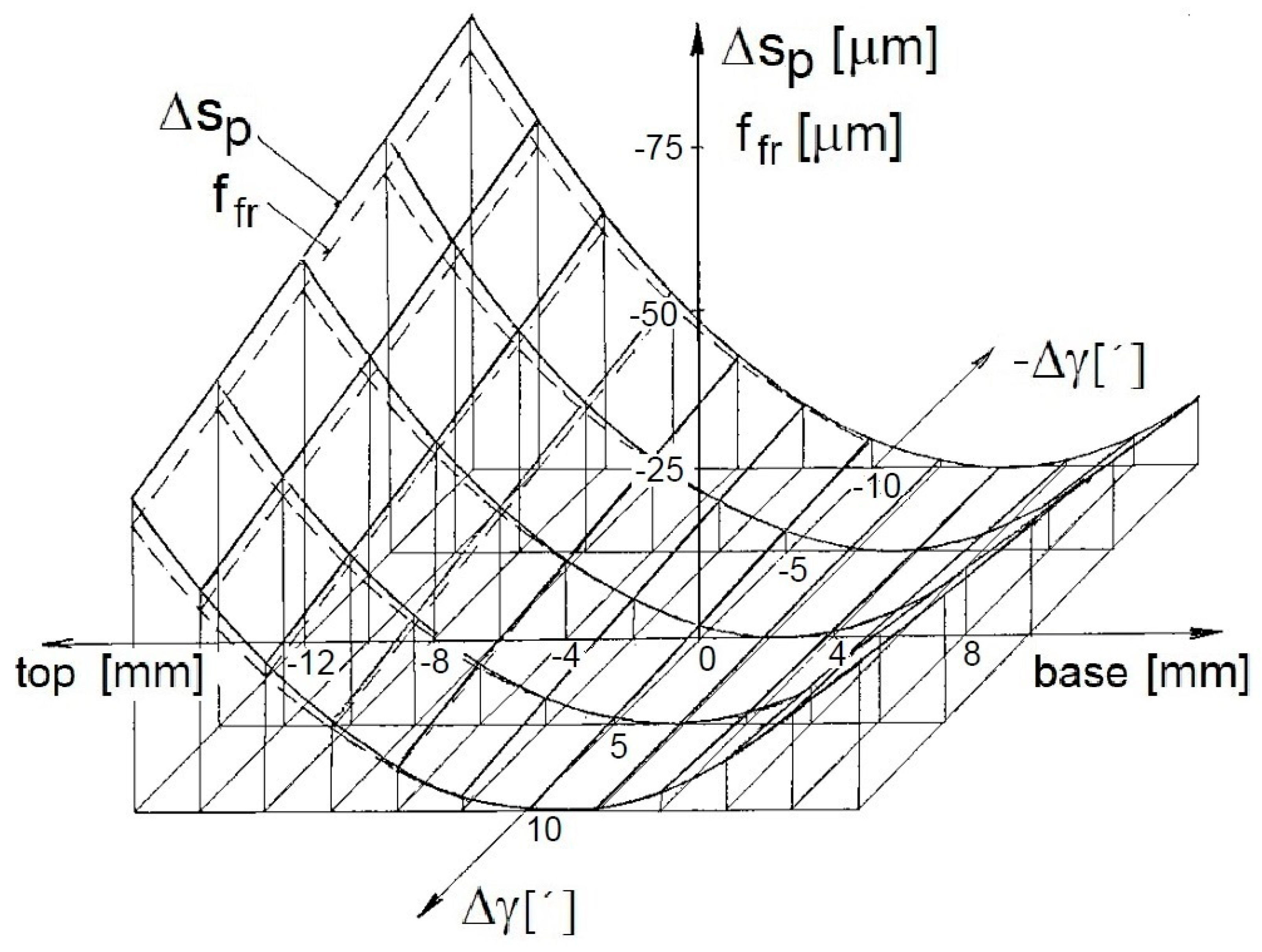
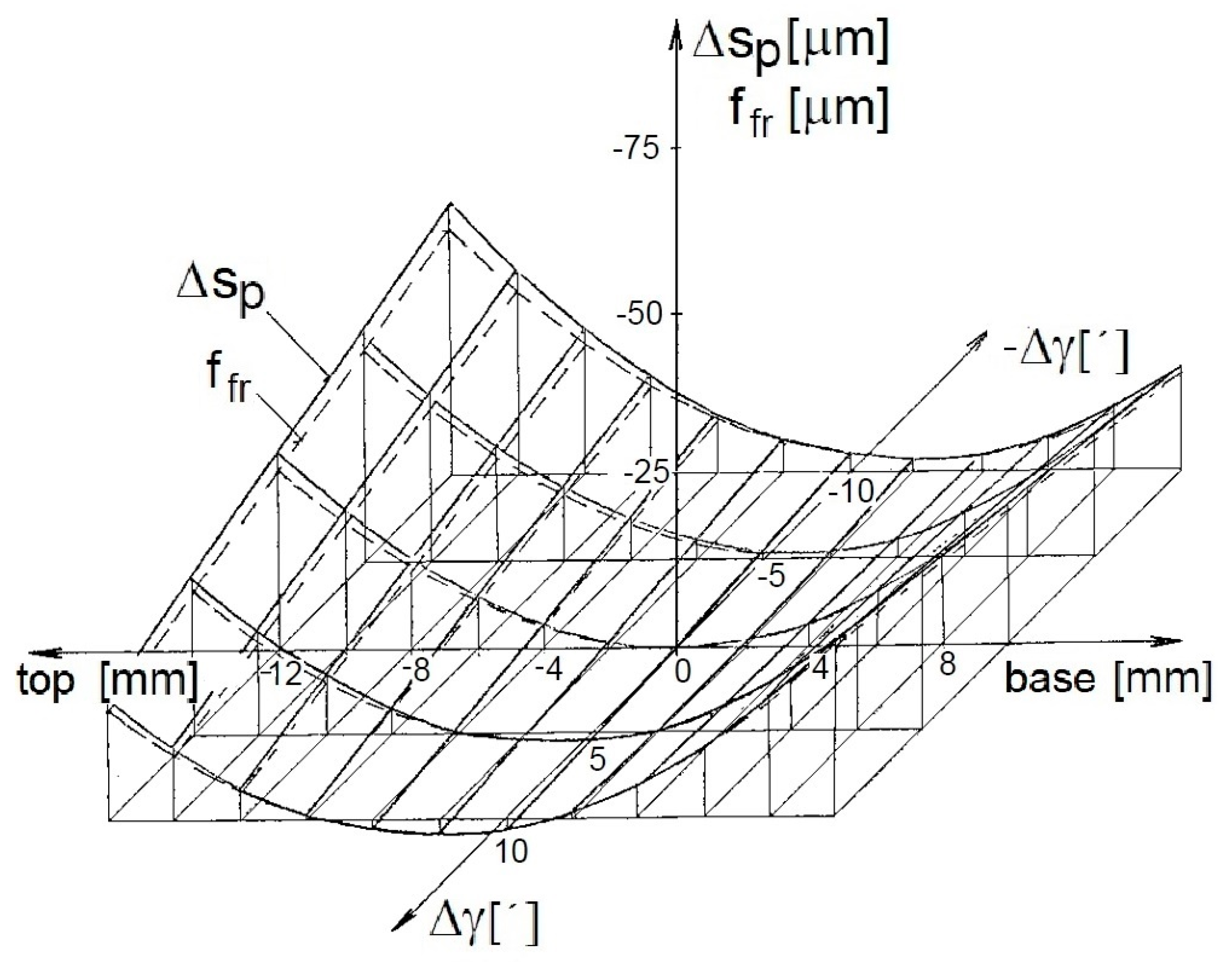
| Δsp | Deviation in the actual profile of the manufactured tooth (μm) |
| γf | Angle of the gradient of the hob (deg) |
| Δγ | Inaccuracy in the setting of the rolling mill (′), |
| λ | Base ridge roll angle (deg) |
| κ | Angle of rotation of the axial cut of the rolling cutter (rad) |
References
- Bouzakis, K.D.; Antoniadis, A. Optimizing of tangential tool shift in gear hobbing. CIRP Ann. 1995, 44, 75–78. [Google Scholar] [CrossRef]
- Jia, K.; Guo, J.; Zheng, S.; Hong, J. A general mathematical model for two-parameter generating machining of involute cylindrical gears. Appl. Math. Model. 2019, 75, 37–51. [Google Scholar] [CrossRef]
- Spitas, V.; Costopoulos, T.; Spitas, C. Fast modeling of conjugate gear tooth profiles using discrete presentation by involute segments. Mech. Mach. Theory 2007, 42, 751–762. [Google Scholar] [CrossRef]
- Vasilis, D.; Nectarios, V.; Aristomenis, A. Advanced computer aided design simulation of gear hobbing by means of three-dimensional kinematics modeling. J. Manuf. Sci. Eng. 2007, 129, 911–918. [Google Scholar] [CrossRef]
- Gupta, K.; Laubscher, R.F.; Davim, J.P.; Jain, N.K. Recent developments in sustainable manufacturing of gears: A review. J. Clean. Prod. 2016, 112, 3320–3330. [Google Scholar] [CrossRef]
- Sałaciński, T.; Przesmycki, A.; Chmielewski, T. Technological aspects in manufacturing of non-circular gears. Appl. Sci. 2020, 10, 3420. [Google Scholar] [CrossRef]
- Maščeník, J.; Pavlenko, S. Determining the exact value of the shape deviations of the experimental measurements. Appl. Mech. Mater. 2014, 624, 339–343. [Google Scholar] [CrossRef]
- Tilavaldiev, B. Methods of manufacturing gears. Int. J. Adv. Sci. Res. 2022, 2, 127–130. [Google Scholar] [CrossRef]
- Lin, C.Y.; Tsay, C.B.; Fong, Z.H. Mathematical model of spiral bevel and hypoid gears manufactured by the modified roll method. Mech. Mach. Theory 1997, 32, 121–136. [Google Scholar] [CrossRef]
- Pavlenko, S.; Maščenik, J.; Krenický, T. Worm Gears: General Information, Calculations, Dynamics and Reliability; RAM-Verlag: Lüdenscheid, Germany, 2018; p. 167. [Google Scholar]
- Das, H.; Li, X.; Li, L.; Schuessler, B.J.; Overman, N.; Darsell, J.T.; Upadhyay, P.; Soulami, A.; Herling, D.R.; Joshi, V.V.; et al. An innovative and alternative approach toward gear fabrication. J. Manuf. Process. 2023, 102, 319–329. [Google Scholar] [CrossRef]
- Bouzakis, K.D.; Lili, E.; Michailidis, N.; Friderikos, O. Manufacturing of cylindrical gears by generating cutting processes: A critical synthesis of analysis methods. CIRP Ann. 2008, 57, 676–696. [Google Scholar] [CrossRef]
- Čep, R.; Janásek, A.; Čepová, L.; Petrů, J.; Hlavatý, I.; Car, Z.; Hatala, M. Experimental testing of exchangeable cutting inserts cutting ability. Teh. Vjesn. 2013, 20, 21–26. [Google Scholar]
- Fan, Q. Enhanced algorithms of contact simulation for hypoid gear drives produced by face-milling and face-hobbing processes. J. Mech. Des. 2007, 129, 31–37. [Google Scholar] [CrossRef]
- Shih, Y.P.; Fong, Z.H.; Lin, G.C. Mathematical model for a universal face hobbing hypoid gear generator. J. Mech. Des. 2007, 129, 38–47. [Google Scholar] [CrossRef]
- Ivanov, V.; Mital, D.; Karpus, V.; Dehtiarov, I.; Zajac, J.; Pavlenko, I.; Hatala, M. Numerical simulation of the system “fixture–workpiece” for lever machining. Int. J. Adv. Manuf. Technol. 2017, 91, 79–90. [Google Scholar] [CrossRef]
- Boral, P.; Stoić, A.; Kljajin, M. Machining of spur gears using a special milling cutter. Teh. Vjesn. 2018, 25, 798–802. [Google Scholar]
- Durante, S.; Comoglio, M.; Rabezzana, F. High Performance Gears Hobbing; Springer: Vienna, Austria, 1999; pp. 207–214. [Google Scholar]
- Habibi, M.; Chen, Z.C.; Fang, Z. Tool wear improvement in face-hobbing of bevel gears by re-designing the cutting blades. IFAC-PapersOnLine 2015, 48, 1888–1893. [Google Scholar] [CrossRef]
- Jurko, J.; Miškiv-Pavlík, M.; Husár, J.; Michalik, P. Turned Surface Monitoring Using a Confocal Sensor and the Tool Wear Process Optimization. Processes 2022, 10, 2599. [Google Scholar] [CrossRef]
- Vimercati, M. Mathematical model for tooth surfaces representation of face-hobbed hypoid gears and its application to contact analysis and stress calculation. Mech. Mach. Theory 2007, 42, 668–690. [Google Scholar] [CrossRef]
- Habibi, M.; Chen, Z.C. A new approach to blade design with constant rake and relief angles for face-hobbing of bevel gears. J. Manuf. Sci. Eng. 2016, 138, 031005. [Google Scholar] [CrossRef]
- Golebski, R.; Boral, P. Study of Machining of Gears with Regular and Modified Outline Using CNC Machine Tools. Materials 2021, 14, 2913. [Google Scholar] [CrossRef] [PubMed]
- Fan, Q. Ease-off and application in tooth contact analysis for face-milled and face-hobbed spiral bevel and hypoid gears. In Theory and Practice of Gearing and Transmissions; Springer: Berlin/Heidelberg, Germany, 2016; pp. 321–339. [Google Scholar]
- Puzyr, R.; Haikova, T.; Majerník, J.; Karkova, M.; Kmec, J. Experimental study of the process of radial rotation profiling of wheel rims resulting in formation and technological flattening of the corrugations. Manuf. Technol. 2018, 18, 106–111. [Google Scholar] [CrossRef]
- Xiang, S.; Li, H.; Deng, M.; Yang, J. Geometric error analysis and compensation for multi-axis spiral bevel gears milling machine. Mech. Mach. Theory 2018, 121, 59–74. [Google Scholar] [CrossRef]
- Ruzbarsky, J.; Mital, G. Diagnostics of selected surface characteristics with laser profilometry. MM Sci. J. 2018, 1, 2140–2214. [Google Scholar] [CrossRef]
- Simon, V.V. Optimal machine-tool settings for the manufacture of face-hobbed spiral bevel gears. J. Mech. Des. 2014, 136, 081004. [Google Scholar] [CrossRef]
- Simon, V.V. Manufacture of optimized face-hobbed spiral bevel gears on computer numerical control hypoid generator. J. Manuf. Sci. Eng. 2014, 136, 031008. [Google Scholar] [CrossRef]
- Gaspar, S.; Pasko, J. Mathematical formulation of the kinematic equations for the control of the robot system with application for the machining conical surfaces. MM Sci. J. 2018, 1, 2158–2161. [Google Scholar] [CrossRef]
- Claudin, C.; Rech, J. Development of a new rapid characterization method of hob’s wear resistance in gear manufacturing—Application to the evaluation of various cutting edge preparations in high speed dry gear hobbing. J. Mater. Process. Technol. 2009, 209, 5152–5160. [Google Scholar] [CrossRef]


Disclaimer/Publisher’s Note: The statements, opinions and data contained in all publications are solely those of the individual author(s) and contributor(s) and not of MDPI and/or the editor(s). MDPI and/or the editor(s) disclaim responsibility for any injury to people or property resulting from any ideas, methods, instructions or products referred to in the content. |
© 2023 by the authors. Licensee MDPI, Basel, Switzerland. This article is an open access article distributed under the terms and conditions of the Creative Commons Attribution (CC BY) license (https://creativecommons.org/licenses/by/4.0/).
Share and Cite
Mascenik, J.; Coranic, T.; Krenicky, T. Options on Tooth Profile Modification by Hob Adjustment. Appl. Sci. 2023, 13, 10646. https://doi.org/10.3390/app131910646
Mascenik J, Coranic T, Krenicky T. Options on Tooth Profile Modification by Hob Adjustment. Applied Sciences. 2023; 13(19):10646. https://doi.org/10.3390/app131910646
Chicago/Turabian StyleMascenik, Jozef, Tomas Coranic, and Tibor Krenicky. 2023. "Options on Tooth Profile Modification by Hob Adjustment" Applied Sciences 13, no. 19: 10646. https://doi.org/10.3390/app131910646
APA StyleMascenik, J., Coranic, T., & Krenicky, T. (2023). Options on Tooth Profile Modification by Hob Adjustment. Applied Sciences, 13(19), 10646. https://doi.org/10.3390/app131910646