Article

Applying the Artificial Neural Network and Response Surface Methodology to Optimize the Drilling Process of Plywood

Faculty of Furniture Design and Wood Engineering, Transilvania University of Brasov, Bd-ul Eroilor nr. 29, 500036 Brasov, Romania
*
Author to whom correspondence should be addressed.
Appl. Sci. 2023, 13(20), 11343; https://doi.org/10.3390/app132011343
Submission received: 23 September 2023 / Revised: 10 October 2023 / Accepted: 13 October 2023 / Published: 16 October 2023

Abstract

:
Plywood is a wood-based composite with many applications in construction, shipbuilding, and furniture production. One of the basic plywood processing and mandatory operations is drilling. Up to now, considerable and very diverse thematic research has been recently carried out on drilling, but little of that deals with modeling of the drilling process of plywood. Therefore, in this work, the artificial neural network modeling technique and response surface methodology were applied to model and optimize the drilling process of plywood. Two artificial neural network models were developed to predict the thrust force and the drilling torque based on drill tip angle, tooth bite, and drill type. The developed ANN models were used to complete the value of responses in the experimental design, which was requested by the response surface methodology. The trust force during the drilling of plywood is significantly influenced by the drill type (helical or flat). The most significant factor that affects the drilling torque during the drilling of plywood is the tooth bite. A helical drill assures a lower minimum thrust force and drilling torque than a flat drill. The proposed method could be used as an optimization tool during the design phase of the furniture manufacturing process.

1. Introduction

Plywood is an engineered product made from wood and it is a part of the large family of wood-based composites, a family that also includes other materials widely used in various economic sectors: particleboards (chipboards), Medium Density Fiberboards (MDFs), Oriented Strand Boards (OSBs), and others. Plywood is a wood-based composite with many uses. Its applications include construction, shipbuilding, furniture production, etc. In 2020, the world’s total plywood production was over 118 billion cubic meters, 1.97% more than in 2019 and 15.1% more than 10 years before [1].
Along with circular blade cutting, drilling is one of the basic plywood processing operations. Unlike these two, milling and sanding are much less used when processing plywood.
Plywood drilling is carried out on the same general principles, with the same tools and machines, and with roughly the same cutting parameters as drilling solid wood or other wood-based materials (chipboard, MDF, OSB etc.). Over time, the drilling of wood composites has been the focus of various research work to study and optimize the process. Various factors such as feed rate, diameter of drill, spindle speed, tip angle, type of drill etc. affects the efficiency of drilling operation that is often quantified through tool durability, cost, and quality of holes. An extensive review regarding the drilling of wood and wood-based materials is presented in the study performed by Gorski [2]. However, regarding the drilling of plywood, there is limited information in the literature.
Podziewski and Górski [3] showed that the feed rate has a significant linear influence on the axial force and on the cutting torque during the drilling of plywood. Moreover, the same scholars, in other work [4], obtained that the effect of spindle speed on the drill advance force is negligible and the relation between feed per revolution and feeding force is proportional.
Rogoziński et al. [5] reveal that plywood produces a smaller amount of fine dust than drilling in high-density fiberboard.
Podziewski and Górski [4] studied how different machining conditions affect the drilling of wood-based materials such as plywood, MDF, and particleboard. They analyzed the effect of the cutting speed and the feed speed on the feed force. The results revealed that the effect of the cutting speed on the feed force is almost negligible in comparison to the other factors such as feed speed and the type of material.
Podziewski et al. [6] studied the machinability of plywood and other types wood-based materials by drilling. The aim of the experiments was to evaluate the quality of the edges of the holes, the cutting force, and torque. The obtained data were used to establish a quality index and cutting force index defined by referencing them to one selected material (MDF). The results revealed that the quality index was not correlated to the cutting force index due to the fact that it is influenced by the internal structure of the type of material used.
Agarwal and Mishra [7] used wooden fibers and epoxy resin to manufacture laminated plywood and medium density fiberboard. The purpose of the study was to examine the effect of drilling parameters on the manufactured materials. Four types of drill bits, with a point angle of 30°, 60°, 90°, and 120°, different cutting speeds and feed rates were used for drilling in order to examine the effect of the delamination factor. The obtained results shows that the delamination factor increases with the increase in the point angle of the drill bit, and also with the increase in the feed speed.
Sydor et al. [8] analyzed the accuracy of holes drilled in the side surface of plywood. The results showed the adhesive layer negatively influences the accuracy of the position and the angle of the holes. In addition to, the study recommends not to use a drill diameter smaller than 3.8 mm. In addition, in order to maintain the hole accuracy, a feed per revolution lower than 0.15 mm/rev. in the second phase of drilling is highly recommended to maintain hole accuracy.
Modeling of the wood drilling process represents a new management principle that leads to high-quality wooden products [9]. Various approaches could be used to model the drilling process of wood and wood-based materials. The most applied method to model and optimize the drilling process is Response Surface Methodology (RSM). In addition, the artificial neural network (ANN) modeling technique was, also, applied to predict the various outputs of the drilling process. Nowadays, ANN models are included in various decision support systems that are developed for the forest industry [10].
Davim et al. [11] studied how to control the delamination factor in the drilling of MDF by testing two types of MDF panels with different coating layers, using cemented carbide drills. They analyzed the main interaction effects of the drilling parameters on the delamination factor. Feed rate and cutting speed were used as independent variables and delamination was measured at the entry and exit of the holes. The authors used response surface methodology to design and model the experiments. ANOVA, also, was used to check the validity of the models.
The article published by Prakash and Palanikumar [12] explores the prediction of surface roughness during the drilling of MDF using response surface methodologies with TiN-coated carbide step drill bits. The experiments, guided by Taguchi’s design technique, involve spindle speed, feed rate, and drill diameter as factors. The study establishes a second-order model through response surface methodology, revealing that the feed rate is the most influential parameter on surface roughness, followed by the cutting speed. The developed model shows a promising predictive accuracy, validated through additional experiments.
The study published by Wang et al. [13] examines delamination’s impact on drilling quality in MDF, specifically focusing on variable feed pressure in multi-spindle drilling machines. Second-order polynomial models are established using response surface methodology to analyze the relationship between delamination and machining parameters. The analysis of variance (ANOVA) validates these models, revealing that delamination increases with decreased drill hardness and increased feed pressure at the MDF entry and exit. At low drill hardness and high feed pressure, the delamination factor remains relatively insensitive to variations in these factors.
The paper of Valarmathi et al. [14] explores how to achieve good surface quality in drilling particleboard by changing the input parameters. It measures the surface roughness (Ra) and finds that it is lowest with a high cutting speed, low feed speed, and small point angle. It uses ANOVA to show that feed speed has the most effect on Ra, followed by point angle and cutting speed. It also uses RSM and adaptive neuro-fuzzy inference system (ANFIS) to make mathematical models to predict Ra and compares their accuracy. The R2 coefficient values of 98.5% (RSM) and 99.9% (ANFIS) indicates that the models are useful to predict the surface roughness of particleboards.
Ayyildiz et al. [15] used a parallel robot to drill MDF and examined the effect of cutting parameters on surface roughness. They used the Taguchi technique and ANOVA to find the best drilling parameters and fit a quadratic regression model. They report that the surface roughness is optimal when the point angle is 118°, the cutting speed is 47.1 m/min, and the feed rate is 0.01 mm/rev.
Bedelean et al. [16] studied how to optimize the drilling process of wood particleboards by adjusting selected factors. They used ANN models and RSM to predict and analyze the effects of drill tip angle, tooth bite, and drill type on delamination factor, thrust force, and drilling torque. The authors found that a helical drill assures a lower delamination factor, a lower thrust force, and a lower drilling torque than a flat drill. The designed ANN models were reliable.
Zbieć [17] developed a neural network to monitor tool wear in MDF milling based on machined surface temperature, cutting force, thrust force, and power consumption. The article of Jegorowa et al. [18] proposes an automatic system to detect the drill bit condition by measuring various signals during machining. It uses k-NN (k-nearest neighbor algorithm) classifier in MATLAB to classify the drill bit as Green (tool can still be used), Red (tool change is necessary), or Yellow (intermediate, warning state). It reports a 76% accuracy of classification.
Based on the information presented above, one could observe that there is a lack of studies regarding the application of ANN and RSM in modeling of the drilling process of plywood. Therefore, the objective of this research is to apply the ANN modeling technique and RSM to model and optimize the drilling process of plywood. The analyzed factors (independent variables) that are considered in this work are drill tip angle, tooth bite, and drill type (flat or helical). The responses (dependent variables) are the thrust force and drilling torque—two dynamic parameters that affect both quality and the energy consumption during drilling of wood and wood-based materials.

2. Materials and Methods

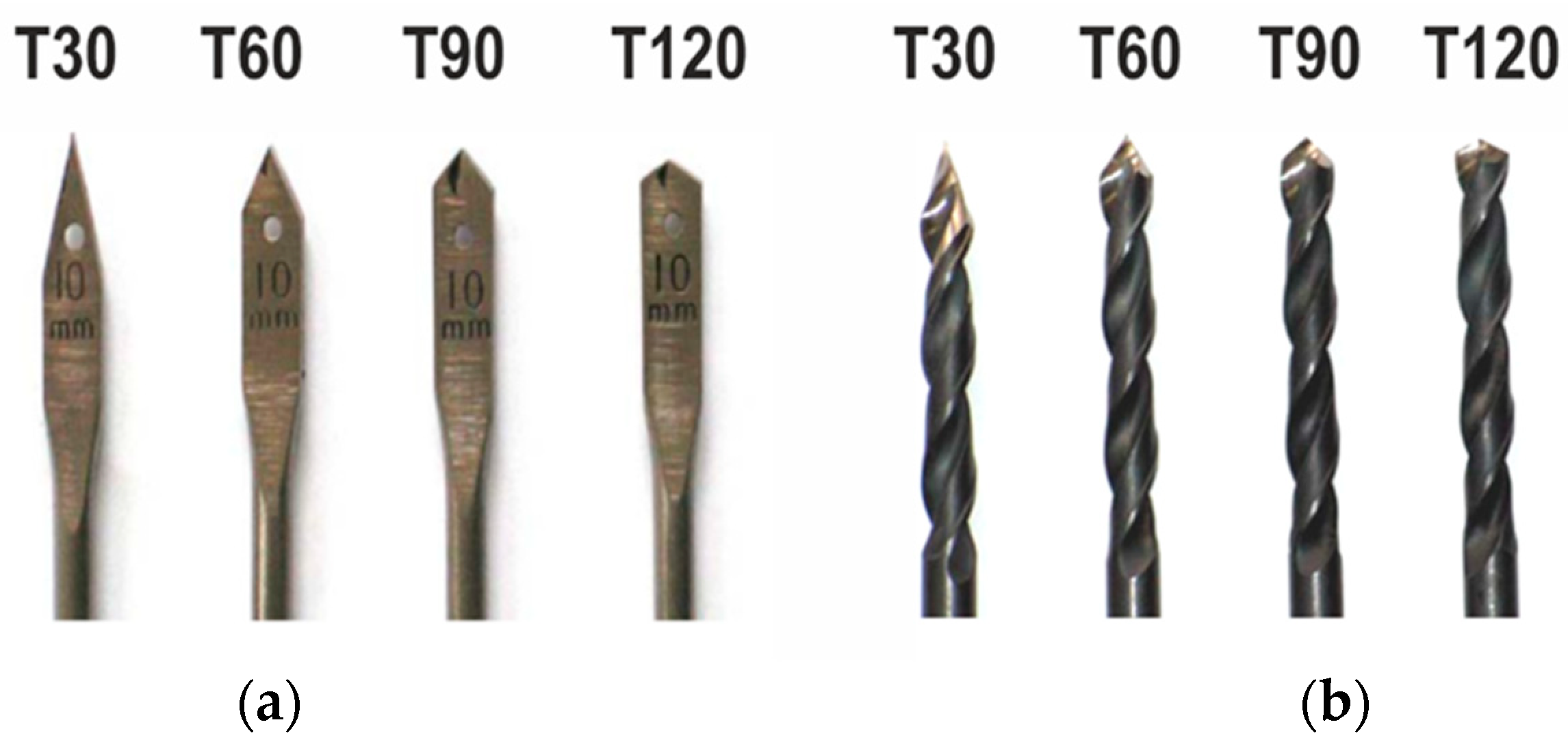
2.1. Experimental Part

The experiments carried out to determine the drilling torque and thrust force used the methodology presented by Ispas and Răcăşan [19]. Two sets of drills were used: four flat drills and four helical drills (Figure 1). All eight drills had a drilling diameter of 10 mm. The drills were sharpened with four values of tip angle (2κr = 30°, 60°, 90°, 120°) and with the same clearance angle α = 20°.
Eighty samples of beech plywood (Figure 2), with a thickness of 18 mm, were used for processing. The rotation speed of the drills was n = 3000 rpm. Four feed speeds were used, vf = 0.6, 1.8, 3.0 and 4.2 m/min. Forty samples were processed with the flat drills, and the other forty with the helical ones. Each group of forty samples was divided into four groups of ten samples, each such group being processed with one of the four feed speeds.
Drilling was performed on an ISEL GFV/GFY CNC machining center. The measured parameters were the thrust force and the active power consumed by the spindle motor during drilling. The thrust force was measured with a device consisting of three HBM force transducers, type S2 (nominal force: 500 N). The measurement of the active power consumed by the spindle motor was performed by a Camille Bauer Sineax P530/Q531 transducer for active and reactive power. The equipment connection scheme is shown in Figure 3.
For data recording, a DAQ Board Keithley Model KUSB-3108 was used with the help of the Keithley KUSB QuickDataAcq software v.1.5.5.0. Data recording was carried out with a frequency of 100 values/s simultaneously on all four channels: three for force sensors and one for the active power.
The processing of the experimental data was carried out with the help of Microsoft Excel under Windows 10. To begin with, a filtering of the data was performed with a fourth-order Butterworth digital filter, in order to remove the parasitic components of the signal.
To determine the thrust force FT, the data from the three force sensors were summed 3 by 3.
To determine the drilling torque TD, the data from the measurement of the active power consumed by the spindle motor were transformed using Formulas (1) and (2).
P D = P T P 0
where:
PD is the power consumed only for the actual drilling, in W;
PT is the total active power consumed by the spindle motor during drilling (and measured), in W;
P0 is the power consumed during idle running, in W.
As known, in rotational motion the mechanical power PD:
PD = TDn
where:
TD is the torque, in Nm;
n is the rotational speed, in rad/s.
Therefore, the torque is: T D = P D n   N m if PD is given in [W] and n in [rad/s].
However, if the rotational speed n is given in [rpm], we must transform the equation according to the new measurement units.
So:
1 r o t m i n = 1 r o t 60 s = 2 π r a d 60 s = 2 π 60 · r a d s 1 9.55 r a d s
Therefore, if PD is given in [W] and n in [rpm]:
T D = 9.55 P D n     N m
where:
n is the rotation speed of the drill, in rpm.
For further processing and analysis, the maximum values of both thrust force FT and drilling torque TD were taken into account.

2.2. Data Modeling

2.2.1. Modeling with Artificial Neural Network

The obtained data set was randomly divided in two subsets. One subset was used to train and test the neural networks that were designed to predict the thrust force (Y1) and drilling torque (Y2) based on drill tip angle (X1), tooth bite (X2), and drill type (X3). The sample size for this subset was 107 in the case of flat drill and 112 in the case of helical drill. The other subsets were used to validate the developed models. In the case of flat drill, the sample size was equal to 15 and in the case of helical drill, the sample size was equal to 17. The main descriptive statistics of both subsets are presented in Table 1. One could observe that both subsets are roughly the same from the point of view of analyzed statistical indicators.
The ANN models were developed by involving the Neural Ware Predict Software (Predict), NeuralWare Inc., Carnegie, 239, PA, USA [20]. This software integrates all the facilities needed to apply neural modeling techniques, namely, data analysis, variable transformation, and reveal the network architecture. Predict is built based on cascade correlation learning algorithm. This algorithm starts with a minimum architecture of the multi-layer perceptron (MLP), which is one of the most popular architectures, and new hidden units are added step by step till the optimum configuration of MLP is achieved. The main structure of MLP architecture is depicted in Figure 4.
The MLP architecture is formed by a number of layers, namely, the input layer, the hidden layer, and the output layer. The input layer receives the input signals and transmits the signals to the hidden layer to be processed. The output layer shows the results of the network. An MLP architecture may contain one or more hidden layers in function to the complexity of the problem that is going to be addressed through ANN modeling technique. Each layer contains various number of neurons or processing elements, which are not connected in the same layer.
The process of developing ANN models begins with training the neural network with a known input and output data set. During the training process, the values of weights and biases are adjusted till the best performance is obtained. The value of weights and biases are saved and could be used to predict outputs with new input values, if the designed neural networks performed well during the testing phase [21].
According to Özşahin [22], the job of one neuron is to receive signals (xi) from the neurons that are located in the previous layer together with its corresponding weight factor (wij), to sum the weighted signals (netj) and the bias of the layer ( θ j ) and to communicate the output (yj) to the next layer. A mathematical (transfer) function (f (.)) is applied to compute the output value (Equations (3) and (4)).
n e t j = i = 1 n x i w i j θ j
y j = f ( n e t j )
The number of neurons in the input layers is equal to the number of inputs of the network.
The number of processing elements or neurons in the hidden layer is typically found by applying the trial–error approach or various optimization algorithms. The number of neurons in the output layers is equal to the number of desired outputs.
Y j = W 0 + j = 1 n x i w i j
Since most of the default settings of Predict are useful in solving useful problems, these settings, also, were applied in this work [20]. The models were designed to have a hyperbolic–tangent transfer function in the hidden layer and a sigmoid transfer function in the output layer. The adaptive gradient learning rule and a learning rate equal to 0.01 was used in this study. The adaptive gradient learning is based on back-propagation technique designed to train the MLP network. This technique employs an objective function to figure out how closely the outputs of the network match the target outputs in the training set of data. The result of objective function is improved by adjusting the weights of each individual processing element (neuron).
The performance of ANN models developed to predict the thrust force and drilling torque was measured using the most applied indicators in literature [20,21,22], namely, coefficient of correlation (R), coefficient of determination (R2), root mean square error (RMSE), and the mean absolute percentage error (MAPE). The corresponding equations are:
R = i = 1 n ( p i p ¯ ) ( a i a ¯ ) i = 1 n ( p i p ¯ ) 2     i = 1 n ( a i a ¯ ) 2
R 2 = 1 i = 1 n ( a i p i ) 2 i = 1 n ( a i p ¯ i ) 2
RMSE = 1 n i = 1 n ( a i p i ) 2
MAPE = 1 n ( i = 1 n [ a i p i a i ] ) × 100
where: a i is the experimental value, p i is the predicted value of ANN model, a ¯ is the mean of experimental values; p ¯ is the mean of predicted values, n is the total number of values.
Coefficient of correlation and coefficient of determination measure the strength of the relationship between experimental and predicted values. When the value of R or R2 is close to one, there could be concluded that there is a strong relationship between experimental and predicted values. On the other hand, a value of R or R2 close to zero indicates that between the experimental and predicted values is a lower relationship. In addition, the value of R2 explains what percentage of variation in the dependent variable could be explained by the analyzed independent variables.
The root mean square error measures the average difference between the experimental and predicted values by the developed models. A value of RMSE close to zero tells us that the predicted values are similar with those that were obtained during the experiments.
The mean absolute percentage error, which represents most performance indicator of ANN models, describes how well the developed models predict the desired outputs. According to Lewis (1982) cited by Özşahin and Singer [21], a value of MAPE lower than 10% indicates that the developed models have a high precision. On the other hand, when the MAPE is higher than 50%, the models are inaccurate. When the MAPE is between 10 and 20%, the models have a good accuracy. A reasonable model is obtained when the MAPE is greater than 20% and lower than 50%.

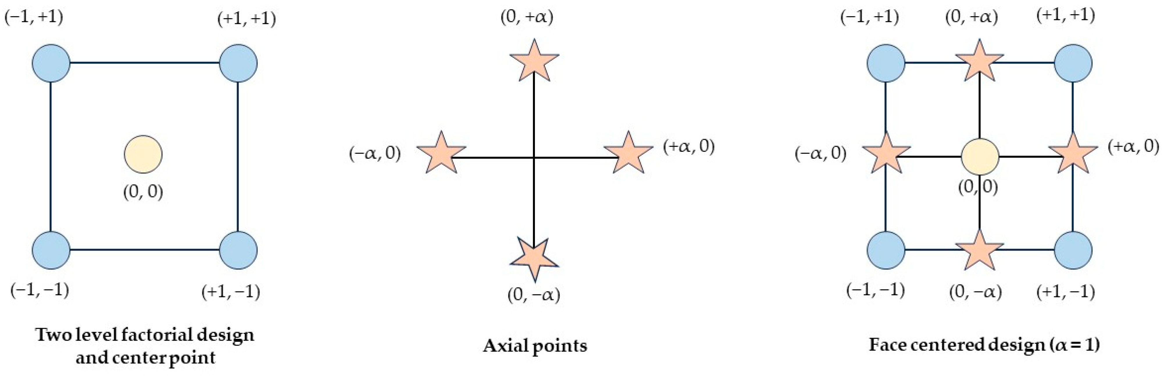
2.2.2. Modeling with Response Surface Methodology

The first step to applying the Response Surface Methodology is to generate a central composite design. In this design, various combinations among the values of factors are generated. The corresponding response of these combinations could be revealed by means of experiments or simulations. Once the experimental design is completed, the next step consists of figuring out the regression equation that best describes the relationship between inputs and output. Usually, the ANOVA is applied to reveal which factors and coefficients are significant from a statistical point of view. The equation in coded form could be used to analyze the influence of factors (inputs) on the analyzed response (output). The equation in real form could be used to make predictions for various scenarios. Last but not least is the step that consists of using the regression equation to reveal the optimum combination of factors that corresponds to the desired output. These steps were performed by means of the Design Expert software (Version 9, Stat-Ease Inc., Minneapolis, MN, US). The experimental design generated by the software is a two-level face centered design (FCCD), which is pictured in Figure 5. The FCCD generates four combinations for the flat drill (#1, #16, #23, and #24) and four combinations for helical drill (#6, #8, #13, and #25) among the low (−1) and high (+1) levels of analyzed factors, namely, drill tip angle (X1) and tooth bite (X2) (Table 2 and Table 3). The two-level factorial points are needed to estimate the linear effect of factors on the analyzed responses. On the other hand, to reveal whether there is a non-linear effect of factors, the FCD design requires taking into account the axial points (α). In Table 4, the axial points are combinations #3, #10, #17, and #18 for the flat drill and combination #4, #14, #19, and #22 in the case of the helical drill. This design also includes combinations among the center level (0) of analyzed factors, which are used during the analysis to estimate the experimental error. These combinations are #2, #11, #15, #20, and #21 in the case of the flat drill and combinations #5, #7, #9, #12, and #26 for the helical drill (Table 3). Summing up, 26 combinations were analyzed. The corresponding value of analyzed responses (thrust force and drilling torque) were revealed by means of designed ANN models.
Once the values of analyzed responses were figured out, a quadratic model could be obtained. The general form is presented in Equation (10) [23]:
Y = β 0 + i = 1 k β i X i + i = 1 k β i i X i 2 + i = 1 k   j = 1 k β i j X i X j + ε
where Y is the dependent variable or the response (thrust force or drilling torque), X i and X j are the analyzed factors, namely, drill tip angle (X1) and tooth bite (X2), β 0 is the constant, β i , β i i , and β i j are the coefficients of the equation, ε is the error term, and k represents the number of analyzed factors.
The coefficient of mathematical models were developed through regression analysis. In order to figure out if the model parameters of each factor are significant, the analysis of variance (ANOVA) was involved. ANOVA was performed at a 1% and 5% level of significance. The coefficient of determination (R2) was used to establish the model accuracy.
For the optimization study, a various combinations of analyzed factors are analyzed to fulfill the optimization criteria, namely, to minimize or maximize the investigated response or responses. In this study, the optimization criteria was to minimize both the thrust force and drilling torque. To determine the best combination among factors, the Design Expert software uses the desirability function approach, which is one of the most widely used methods in the industry for the optimization of multiple response processes. The method finds operating conditions that provide the most desirable response values. According to literature [24,25], for each response Yi(X), the desirability function di(Yi) assigns numbers between 0 and 1 to the possible values of Yi. When the di(Yi) is close to zero (0) there is an undesirable value of Yi. On the other hand, when the di(Yi) is close or equal to one (1), there is a desirable value of analyzed dependent variable (response). All individual desirabilities are combined by means of geometric mean that describes the overall desirability, D (Equation (11)):
D = d 1 Y 1   ×   d 2 Y 2   ×   . . .   ×   d n Y n 1 / n
where n represents the number of responses being optimized.

3. Results and Discussion

3.1. ANN Modeling

In Table 4, various architectures of designed ANN models that are able to predict the thrust force and drilling torque during drilling of plywood can be observed. Based on the coefficient of correlation (R), the following findings were revealed. The most important input that affects the performance of a designed ANN model to predict the thrust force (Y1) is the drill type (X1), followed by the tooth bite (X2) and drill tip angle (X1). In the case of the model developed to predict the drilling torque (Y2), the tooth bite has a greater influence than the other two analyzed variables, namely, drill tip angle (X1) and drill type (X3). The drill type has a more important role in the performance of model than the drill tip angle (X1). However, the best performance of both designed ANN models is obtained for the case when all three input variables were considered in the model. The coefficient of correlation was equal to 0.98 for both ANN models.
The performance indicators of ANN developed models are presented in Table 5. As can be observed, the developed models have a good accuracy, namely, a high R or R2, and a low RMSE or MAPE. This affirmation is also supported by Figure 6 and Figure 7.
The architecture of designed ANN models is different in the hidden layer both in the case of thrust force and drilling torque when it is compared with the architecture developed to predict the same outputs. However, in the case of prelaminated wood particle panels [16], the number of neurons in the hidden layer was equal to four in the case of the ANN model developed to predict the thrust force and nine for the model designed to predict the drilling torque. Since the same inputs and outputs were analyzed, the difference in the number of neurons could be attributed to the analyzed material in this work, namely, plywood, which has a different structure than prelaminated wood particle panels. Thus, it could be stated that the type of material influences the architecture and performance of artificial neural networks. Consequently, in a further study, the type of material should be included as one of the input of neural networks among other factors.
To summarize, both developed ANN models have a high coefficient of determination (R2 ≈ 0.97). Consequently, the designed models explain at least 97% of experimental data used during the modeling process. By comparing the value of coefficient of determination with the results from other studies, one could observed that the value is close to the value obtained by Tiryaki et al. [26] to predict power consumption during wood planning, Özşahin and Singer [21] to predict noise emissions during wood machining, Tiryaki et al. [27] to predict surface roughness and power consumption during the abrasive machining of wood, and Bedelean et al. [16] to predict the thrust force and drilling torque during the drilling of prelaminated wood particle panels.

3.2. Response Surface Methodology

3.2.1. Thrust Force

The Design Expert software suggests that the relation between the analyzed factors (drill tip angle, tooth bite, and drill type) and thrust force could be best described by Equation (12), which is in coded form. The model is significant at 1% (Table 6). Therefore, one could observe that the trust force during the drilling of plywood is significantly influenced by the drill type (X3). In addition, the drill tip angle (X1) and tooth bite (X2) influence the thrust force (Y1). The tooth bite has a bigger influence than the drill tip angle (X2 > X1) in the case of thrust force during the drilling of plywood. This result is the same as that obtained in our previous work wherein the drilling of prelaminated wood-particle boards was analyzed and optimized [16]. In addition, this result is correlated with the data reported in the literature for the plywood and prelaminated particle board panels, namely, it is stated that the feed rate affects the thrust force [3,28]. Consequently, a low feed rate leads to a low thrust force, and a high feed rate implies a high thrust force. The tooth bite has a non-linear effect on the thrust force. This finding tells us that the optimum value of the tooth bite stands inside the analyzed range (0.1–0.7 mm). Moreover, the statistical analysis reveals the fact that there is an interaction effect of analyzed factors on thrust force (X2X3 > X1X2 > X1X3). The most significant interaction is between the tooth bite (X2) and drill type (X3). This result is the same with that obtained in the case of prelaminated wood-particle boards [16]. The influence of the drill tip angle (X1) and tooth bite (X2) on thrust force (Y1) is plotted in Figure 8. Equations (13) and (14) could be used to predict the thrust force (Y1) based on the drill tip angle (X1) and tooth bite (X2) during drilling of plywood. Equation (13) is for the flat drill and Equation (14) is for the helix drill.
Y ^ 1 c o d e d = 192.55 + 18.51 X 1 + 56.27 X 2 120.64 X 3 + 11.39 X 1 X 2 + 9.16 X 1 X 3 46.85 X 2 X 3 + 13.44 X 1 2 21.31 X 2 2 2.34 X 1 X 2 X 3 24.53 X 1 2 X 3 + 27.95 X 2 2 X 3
Y ^ 1 f l a t = 208.52 3.01 X 1 + 705.33 X 2 + 1.016 X 1 X 2 + 0.018 X 1 2 547.35 X 2 2
Y ^ 1 h e l i x   = 14.34 + 1.16 X 1 77.87 X 2 + 0.67 X 1 X 2 0.0055 X 1 2 + 73.75 X 2 2
The ANOVA results are significant at 5% (α = 0.05) and are presented in Table 6.
When the p-value was less than 0.05, the analyzed factors were significant at 95% confidence level. Therefore, it could be concluded that the next model terms are significant: X1, X2, X3, X2X3, X 2 2 , X 1 2 X 3 , X 2 2 X 3 .

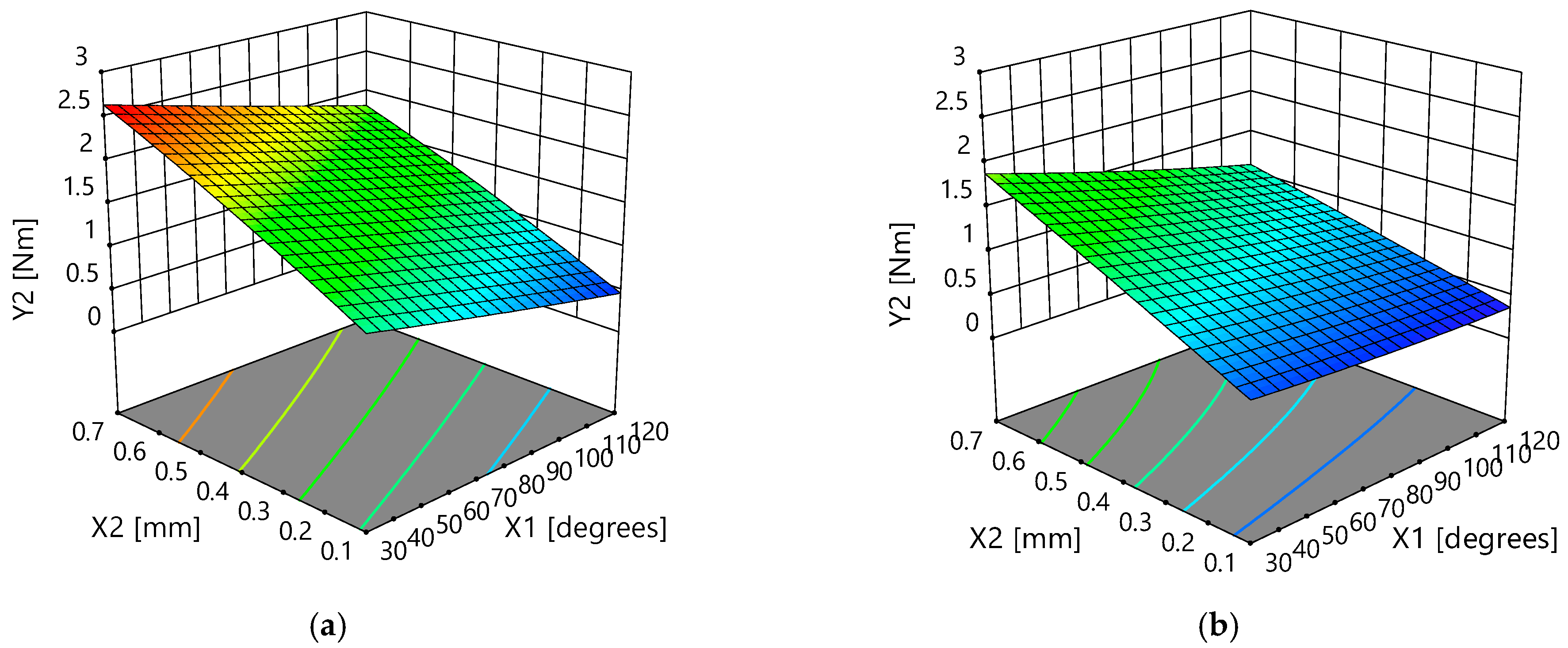
3.2.2. Drilling Torque

The relation between the analyzed factors, drill bit angle (X1), tooth bite (X2) and drill type (X3), and drilling torque (Y2) is described by a quadratic regression equation, which was also revealed by the Design Expert software. The coded form of the suggested mathematical model, which is significant at 1% (Table 7), is presented in Equation (15). This regression equation (in coded form) tells us that the most significant factor (from the analyzed ones) that affects the drilling torque during the drilling of plywood is the tooth bite (X2). The next ones are the drill tip angle (X1) and drill type (X3) with almost the same influence (since both factors have a coefficient close to 0.30). The obtained results are almost identical with those obtained in the case of drilling prelaminated wood particleboard panels [16]. There is a significant interaction between the analyzed factors (X1X2, X1X3, X2X3, X1X2X3) on the drilling torque (Y2). The most important interaction is between tooth bite (X2) and drill type (X3). The influence of drill tip angle (X1) and tooth bite (X2) on the drilling torque (Y2) is presented in Figure 9. Equations (16) (in the case of a flat drill) and 17 (in case of a helical drill) could be used to predict the drilling torque during the drilling of plywood (Y2) based on the drill tip angle (X1) and tooth bite (X2). The ANOVA results at 5% significance level are presented in Table 7.
Y ^ 2 c o d e d = 1.26 0.31 X 1 + 0.62 X 2 0.30 X 3 0.092 X 1 X 2 + 0.067 X 1 X 3 0.094 X 2 X 3 + 0.020 X 1 2 0.032 X 2 2 0.062 X 1 X 2 X 3 + 0.0077 X 1 2 X 3 + 0.017 X 2 2 X 3
Y ^ 2 f l a t = 1.11 0.008 X 1 + 2.97 X 2 0.022 X 1 X 2 + 6.058 e 006 X 1 2 0.54 X 2 2
Y ^ 2 h e l i x   = 0.37 0.0028 X 1 + 2.73 X 2 0.0113 X 1 X 2 + 1.373 e 005 X 1 2 0.164 X 2 2
The optimum combinations of independent variables during the drilling of plywood in order to achieve both a lower thrust force and a lower drilling torque are presented in Table 8. In the case of the helical tool, the drill tip angle (X1) should be equal to 30° and the tooth bite (X2) equal to 0.1. The relative error, which was calculated using Equation (18), between predicted and experimental values is around 25% in the case of thrust force (Y1) and around 5% in the case of drilling torque (Y2). Regarding the flat tool, the minimum thrust force (Y1) and drilling torque (Y2) is obtained when the drill tip angle (X1) is equal to 118° and the tooth bite (X2) is adjusted at the minimum analyzed level (0.1 mm). The relative error of regression equations that were obtained in the case of the flat drill is lower (between 2.14% and 2.65%) than the error obtained for the helical drill (Table 8). Since the desirability coefficient has a high value in the case of the helical drill, it is obviously that this kind of drill performs better in terms of energy consumption during drilling of plywood, than a flat tool. The obtained results are correlated with our previous study regarding the drilling of prelaminated wood particle boards [16].
E R = Y       Y ^ Y   ×   100
where ER is the relative error (%), Y is the experimental value, and Y ^ is the predicted value.

4. Conclusions

In this study, it was shown that the artificial neural network modeling technique could be successfully applied to predict the trust force and drilling torque during the drilling of plywood. The inputs of ANN models were drill tip angle, tooth bite, and drill type. To reveal the optimum combination of factors during the drilling of plywood, the response surface methodology was also applied in this study, together with a face centered composited design, which was completed by using the designed ANN models. Based on the applied methodology, it was revealed that the most important factor that affects the thrust force during the drilling of plywood is drill type. On the other hand, the drilling torque is most influenced by the tooth bite. A helical drill assures a lower thrust force and drilling torque than a flat drill during drilling of plywood. To increase the performance and applicability of designed ANN models, other factors should be taken into account such as the diameter of the drill bit, tool wear, properties of material, rotation speed, and direction of drilling (perpendicular or parallel to veneer layers). Moreover, a probabilistic modeling approach could represent a tool that could improve the predictability of ANN models. In addition, these kinds of models could be integrated with sensor–fusion technique to assure the transition towards the fourth phase of Industrial Revolution (Industry 4.0 concept) that is based on interconnectivity, machine learning, automation, and real-time data processing.

Author Contributions

Conceptualization, B.B. and M.I.; methodology, B.B., M.I. and S.R.; software, B.B. and S.R.; validation, B.B.; resources, S.R.; writing—original draft preparation, B.B. and M.I.; writing—review and editing, M.I. and B.B.; visualization, S.R. All authors have read and agreed to the published version of the manuscript.

Funding

This research received no external funding.

Institutional Review Board Statement

Not applicable.

Informed Consent Statement

Not applicable.

Data Availability Statement

Not Applicable.

Conflicts of Interest

The authors declare no conflict of interest.

References

  1. Food and Agriculture Organization Corporate Statistical Database (FAOSTAT). Available online: https://www.fao.org/faostat/en/#home (accessed on 30 August 2023).
  2. Górski, J. The Review of New Scientific Developments in Drilling in Wood-Based Panels with Particular Emphasis on the Latest Research Trends in Drill Condition Monitoring. Forests 2022, 13, 242. [Google Scholar] [CrossRef]
  3. Podziewski, P.; Górski, J. Effect of the feed rate on the cutting forces during drilling in a standard hardwood plywood. Ann. WULS–SGGW. For. Wood Technol. 2012, 79, 170–172. [Google Scholar]
  4. Podziewski, P.; Górski, J. Relationship between machining conditions and feed force during drilling in some wood-based materials. Ann. Wars. Univ. Life Sci.-SGGW For. Wood Technol. 2011, 75, 216–219. [Google Scholar]
  5. Rogoziński, T.; Wilkowski, J.; Górski, J.; Czarniak, P.; Podziewski, P.; Szymanowski, K. Dust creation in CNC drilling of wood composites. BioResources 2015, 10, 3657–3665. [Google Scholar] [CrossRef]
  6. Podziewski, P.; Szymanowski, K.; Górski, J.; Czarniak, P. Relative machinability of wood-based boards in the case of drilling–Experimental study. BioResources 2018, 13, 1761–1772. [Google Scholar] [CrossRef]
  7. Agarwal, G.; Mishra, A. Fatigue Behavior of Wooden Fiber Reinforced Epoxy Composites. AIP Conf. Proceeding 2021, 2317, 020024. [Google Scholar] [CrossRef]
  8. Sydor, M.; Rogoziński, T.; Stuper-Szablewska, K.; Starczewski, K. The accuracy of holes drilled in the side surface of plywood. BioResources 2020, 15, 117–129. [Google Scholar] [CrossRef]
  9. Hosseini, S.M.; Peer, A. Wood Products Manufacturing Optimization: A Survey. IEEE Access 2022, 10, 121653–121683. [Google Scholar] [CrossRef]
  10. Lapshin, V.P.; Turkin, I.A.; Omelechko, V.U. Automation the Processes of Wood Processing by Drilling, Due to the Development a Mathematical Apparatus for Accounting the Interrelated Feed Drive and Drive of Cutting. In Advances in Automation III; RusAutoCon 2021. Lecture Notes in Electrical Engineering 2021; Radionov, A.A., Gasiyarov, V.R., Eds.; Springer: Cham, Switzerland, 2021; Volume 857, pp. 14–24. [Google Scholar] [CrossRef]
  11. Davim, J.P.; Gaitonde, V.N.; Karnik, S.R. An investigative study of delamination in drilling of medium density fibreboard (MDF) using response surface models. Int. J. Adv. Manuf. Technol. 2008, 37, 49–57. [Google Scholar] [CrossRef]
  12. Prakash, S.; Palanikumar, K. Modeling for prediction of surface roughness in drilling MDF panels using response surface methodology. J. Compos. Mater. 2011, 45, 1639–1646. [Google Scholar] [CrossRef]
  13. Wang, K.; Wang, C.; Gao, M. Investigation on Delamination Factor in Drilling Medium Density Fiberboards with Variable Feed Pressure using Multi-Spindle Drill. Adv. Mater. Res. 2013, 690–693, 2529–2534. [Google Scholar] [CrossRef]
  14. Valarmathi, T.N.; Palanikumar, K.; Sekar, S.; Latha, B. Investigation of the effect of process parameters on surface roughness in drilling of particleboard composite panels using adaptive neuro fuzzy inference system. Mater. Manuf. Process. 2020, 35, 469–477. [Google Scholar] [CrossRef]
  15. Ayyildiz, E.A.; Ayyildiz, M.; Kara, F. Optimization of Surface Roughness in Drilling Medium-Density Fiberboard with a Parallel Robot. Adv. Mater. Sci. Eng. 2021, 2021, 1–8. [Google Scholar] [CrossRef]
  16. Bedelean, B.; Ispas, M.; Răcășan, S.; Baba, M.N. Optimization of Wood Particleboard Drilling Operating Parameters by Means of the Artificial Neural Network Modeling Technique and Response Surface Methodology. Forests 2022, 13, 1045. [Google Scholar] [CrossRef]
  17. Zbieć, M. Application of neural network in simple tool wear monitoring and identification system in MDF milling. Drv. Ind. 2011, 62, 43–54. [Google Scholar] [CrossRef]
  18. Jegorowa, A.; Górski, J.; Kurek, J.; Kruk, M. Use of nearest neighbors (k-NN) algorithm in tool condition identification in the case of drilling in melamine faced particleboard. Maderas. Cienc. Tecnol. 2020, 22, 18–196. [Google Scholar] [CrossRef]
  19. Ispas, M.; Răcăşan, S. The influence of the tool point angle and feed rate on the dynamic parameters at drilling coated particleboard. Pro Ligno 2015, 11, 457–463. [Google Scholar]
  20. NeuralWare. NeuralWorks Predict. In User Guide 2009; Carnagie: New York, NY, USA, 2009. [Google Scholar]
  21. Özşahin, S.; Singer, H. Prediction of noise emission in the machining of wood materials by means of an artificial neural network. N. Z. J. For. Sci. 2022, 52, 1–10. [Google Scholar] [CrossRef]
  22. Ozsahin, S. Optimization of process parameters in oriented strand board manufacturing with artificial neural network analysis. Eur. J. Wood Prod. 2013, 71, 769–777. [Google Scholar] [CrossRef]
  23. Hazir, E.; Koc, K.H.; Baray, S.A.; Esnaf, S. Improvement of adhesion strength for wood-based material coating process using design of experiment methodology. Eur. J. Wood Prod. 2020, 78, 301–312. [Google Scholar] [CrossRef]
  24. Ebadi, S.E.; Ashaari, Z.; Jawaid, M. Optimization and empirical modelling of physical properties of hydrothermally treated oil palm wood in different buffered media using response surface methodology. BioResources 2021, 16, 2385–2405. [Google Scholar] [CrossRef]
  25. NIST/SEMATECH. e-Handbook of Statistical Methods. Available online: http://www.itl.nist.gov/div898/handbook/ (accessed on 28 August 2023).
  26. Tiryaki, S.; Malkoçoğlu, A.; Özşahin, Ş. Artificial neural network modeling to predict optimum power consumption in wood machining. Drewno 2016, 59, 109–125. [Google Scholar] [CrossRef]
  27. Tiryaki, S.; Özşahin, Ş.; Aydin, A. Employing artificial neural networks for minimizing surface roughness and power consumption in abrasive machining of wood. Eur. J. Wood Prod. 2017, 75, 347–358. [Google Scholar] [CrossRef]
  28. Valarmathi, T.N.; Palanikumar, K.; Latha, B. Measurement and analysis of thrust force in drilling of particle board (PB) composite panels. Measurement 2013, 46, 1220–1230. [Google Scholar] [CrossRef]
Figure 1. The drill bits used in the experiments: (a) flat drills; (b) helical drills.
Applsci 13 11343 g001
Figure 2. The plywood samples used during drilling experiments.
Applsci 13 11343 g002
Figure 3. Connection diagram of the equipment for measuring the dynamic parameters of the drill.
Applsci 13 11343 g003
Figure 4. The multi-layer perceptron architecture.
Applsci 13 11343 g004
Figure 5. The structure of a face centered composite design.
Applsci 13 11343 g005
Figure 6. The graphical comparison between the experimental and predicted values of thrust force: linechart (a) and scatter plot (b).
Applsci 13 11343 g006
Figure 7. The graphical comparison between the experimental and predicted values of drilling torque: line chart (a) and scatter plot (b).
Applsci 13 11343 g007
Figure 8. The influence of the drill tip angle and tooth bite on the thrust force: flat drill (a) and helical drill (b).
Applsci 13 11343 g008
Figure 9. The influence of the drill tip angle and tooth bite on the thrust force: (a) flat drill (a,b) helical drill.
Applsci 13 11343 g009
Table 1. Descriptive statistics of training and validation data sets.
VariablesTraining Data Set (nFlat = 107, nHelix = 112)Validation Data Set (nFlat = 15, nHelix = 17)
MSDMinMaxMSDMinMax
FlatHelixFlatHelixFlatHelixFlatHelixFlatHelixFlatHelixFlatHelixFlatHelix
Drill tip angle (X1)7576.8233.4633.26303012012078.0077.6433.6435.273030120120
Tooth bite (X2)0.400.400.220.220.10.10.70.70.420.400.220.210.100.100.70.70
Thrust force (Y1)309.7969.92138.4223.42166.1616.05505.49116.36318.0474.5692.1232.88180.5531.44454.68170.67
Drilling torque (Y2)1.550.950.630.430.470.282.911.971.590.940.720.440.500.292.761.76
M—mean; SD—standard deviation; Min—minimum value; Max—maximum value; n—data set size.
Table 2. The name of factors and their analyzed levels.
Numeric FactorLevel
−α *−10+1+α *
Drill tip angle (X1), °303075120120
Tooth bite (X2), mm0.10.10.40.70.7
Categoric factorLevel 1Level 2
Drill type (X3)Flat (−1)Helical (+1)
* axial points.
Table 3. The experimental plan that was used for the optimization study.
Combination #Factors (Inputs)Responses (Outputs)
Drill Tip Angle (X1), °Tooth Bite (X2), mmDrill Type (X3)Thrust Force (Y1), NDrilling Torque (Y2), Nm
130 (−1)0.1 (−1)Flat (−1)173.871.14
275 (0)0.4 (0)Flat (−1)313.981.55
3120 (+α)0.4 (0)Flat (−1)333.091.17
4120 (+α)0.4 (0)Helical (1)91.910.73
575 (0)0.4 (0)Helical (1)71.080.96
6120 (1)0.7 (1)Helical (1)114.541.11
775 (0)0.4 (0)Helical (1)71.080.96
8120 (1)0.1 (−1)Helical (1)72.290.37
975 (0)0.4 (0)Helical (1)71.080.96
1075 (0)0.7 (+α)Flat (−1)329.952.29
1175 (0)0.4 (0)Flat (−1)313.981.55
1275 (0)0.4 (0)Helical (1)71.080.96
1330 (−1)0.7 (1)Helical (1)42.461.89
1475 (0)0.1 (-α)Helical (1)76.530.42
1575 (0)0.4 (0)Flat (−1)313.981.55
1630 (−1)0.7 (1)Flat (−1)387.752.58
1775 (0)0.1 (-α)Flat (−1)193.950.77
1830 (-α)0.4 (0)Flat (−1)365.282.01
1975 (0)0.7 (+α)Helical (1)84.721.46
2075 (0)0.4 (0)Flat (−1)313.981.55
2175 (0)0.4 (0)Flat (−1)313.981.55
2230 (-α)0.4 (0)Helical (1)33.881.24
23120 (1)0.1 (−1)Flat (−1)190.580.51
24120 (1)0.7 (1)Flat (−1)459.361.82
2530 (−1)0.1 (−1)Helical (1)36.400.53
2675 (0)0.4 (0)Helical (1)71.080.96
Table 4. Results obtained during the influence of independent variable on the performance of ANN models.
Independent VariableNumber of Neurons
in the Hidden Layer
Testing Performance Indicator, R
ANN Model for Thrust ForceANN Model for Drilling TorqueANN Model for Thrust ForceANN Model for Drilling Torque
Drill tip angle (X1) 130.0740.389
Tooth bite (X2)030.3770.768
Drill type (X3)000.8660.436
Drill tip angle (X1) × Tooth bite (X2)420.3720.839
Drill tip angle (X1) × Drill type (X3)260.8720.627
Tooth bite (X2) × Drill type (X3)270.9770.890
Drill tip angle (X1) × Tooth bite (X2) × Drill type (X3)1440.9860.988
Table 5. The performance indicators of ANN models designed to predict the thrust force and drilling torque.
Performance IndicatorANN Model for Thrust ForceANN Model for Drilling Torque
R0.9860.988
R20.9720.976
RMSE16.590.10
MAPE6.807.39
Table 6. Results obtained during ANOVA analysis of the model selected to predict the trust force.
SourceSum of SquaresdfMean SquareF-Valuep-Value
Prob > F
Observation
Model447,346.211140,667.8398.51<0.0001Significant
Drill tip angle (X1)4110.9714110.979.960.0070Significant
Tooth bite (X2)37,989.69137,989.6992.02<0.0001Significant
Drill type (X3)168,825.111168,825.11408.95<0.0001Significant
X1X21037.2911037.292.510.135Not Significant
X1X31005.8411005.842.440.140Not Significant
X2X326,335.85126,335.8563.79<0.0001Significant
X12997.941997.942.420.142Not Significant
X222508.9012508.906.080.02Significant
X1X2X343.78143.780.110.749Not Significant
X12X33324.2913324.298.050.0132Significant
X22X34315.1114315.1110.450.006Significant
R20.98
Table 7. Results obtained during ANOVA analysis of the model selected to predict the drilling torque.
SourceSum of SquaresdfMean SquareF-Valuep-Value
Prob > F
Observation
Model8.15110.74613.64<0.0001Significant
Drill tip angle (X1)1.1311.13935.99<0.0001Significant
Tooth bite (X2)4.5914.593803.62<0.0001Significant
Drill type (X3)1.0411.04862.460<0.0001Significant
X1X20.06710.06755.79<0.0001Significant
X1X30.05410.05444.52<0.0001Significant
X2X30.1110.1188.57<0.0001Significant
X120.002210.00221.840.196Not Significant
X220.005510.00554.600.05Not Significant
X1X2X30.03010.03125.330.0002Significant
X12X30.0003310.00030.280.60Not Significant
X22X30.0015710.00151.310.27Not Significant
R20.99
Table 8. Optimization criteria and optimal solutions obtained in the case of plywood samples drilling.
Independent VariablesGoal SettingsMinimum ValueMaximum ValueLevel of Factor Importance
Drill tip angle (X1)In range301203
Tooth bite (X2)0.10.73
Drill type (X3)FlatHelical3
Dependent variables
Thrust force (Y1)Minimize38.88459.363
Drilling torque (Y2)0.362.583
Optimal solutions
X1X2X3Trust Force (N)Drilling Torque (Nm)D
Y 1 ^ Y1ER1 Y 2 ^ Y2ER2
300.1Helical39.4231.4425%0.5350.564.46%0.955
1180.1Flat191.80196 a2.14%0.4770.49 a2.65%0.773
a—drill tip angle was considered equal to 120°.
Disclaimer/Publisher’s Note: The statements, opinions and data contained in all publications are solely those of the individual author(s) and contributor(s) and not of MDPI and/or the editor(s). MDPI and/or the editor(s) disclaim responsibility for any injury to people or property resulting from any ideas, methods, instructions or products referred to in the content.

