2. Materials and Methods
The theoretical studies were carried out using the methods of mathematical modeling and theoretical mechanics, as well as methods for compiling computer programs and analyzing the results of calculations on a PC and graphical dependencies.
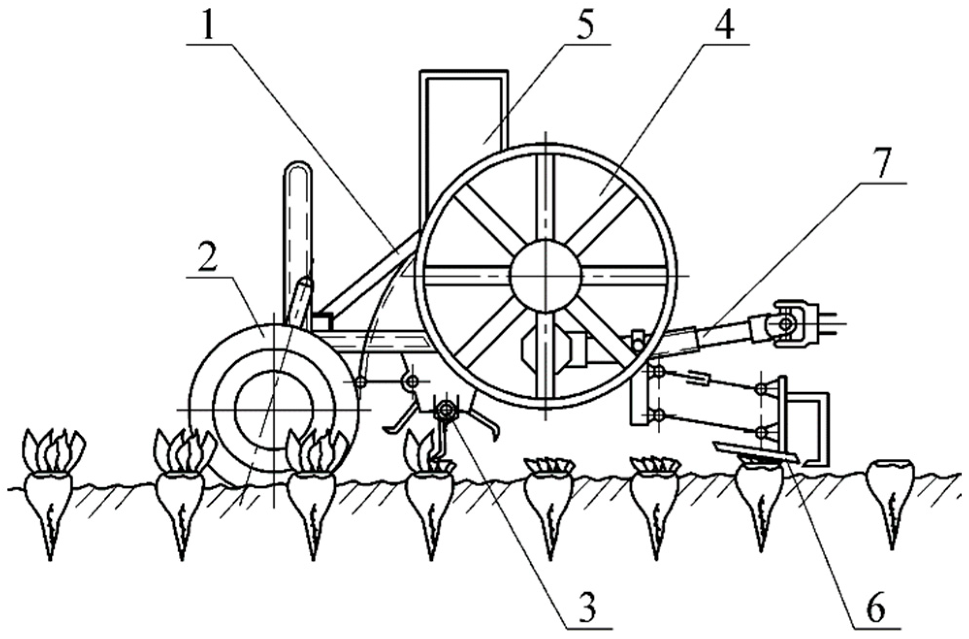
We have developed a new haulm harvester, equipped with a loading mechanism for loading the haulm after its copyless cut with a cutting apparatus to be loaded into a vehicle in addition to the haulm harvester. The main structural element of this loading mechanism is a blade thrower, with the possibility of using blades of various geometric shapes [
24]. The design and technological scheme of the haulm harvester with an improved loading mechanism are shown in
Figure 1.
As shown in the equivalent scheme, the haulm harvester performs a copyless cut of the sugar beet tops without extracting the root crop from the soil, using a rotary haulm harvesting apparatus 3. After that, the haulm, cut across the entire working width, is transported to the end part of the haulm harvester and fed to the loading mechanism, namely, to the blade thrower 4. The blades of the thrower 4 disperse portions of the haulm, located on them, and direct them to the unloading pipe 5, through which the haulm is fed into the body of the vehicle, moving beside the haulm harvester. An important element of the technological process of haulm loading is that the blades during rotation create air pressure, which also contributes to the more efficient movement of the haulm into the vehicle. In other words, the thrower additionally works as a fan.
In order to substantiate the rational parameters of the haulm loading mechanism, it is necessary to build a mathematical model of this process from the moment it hits the thrower blade and the process of particle acceleration by the blades, then its movement along the cylindrical and rectilinear parts of the casing (the unloading pipe), and, finally, the process of haulm flight into the body of the transport funds after departure from the unloading pipe [
25].
Let us first construct a calculated mathematical model for the movement of a haulm particle along the thrower blade from the moment it hits the blade until the moment it leaves the blade. It should be immediately noted that such a model has already been built without taking into account the airflow force created by the blades during the rotation of the thrower and significantly affecting the relative speed of haulm particle movement along the throwing blade [
26]. Therefore, in this article, we will build a refined mathematical model of haulm particle movement along the throwing blade, namely, taking into account the influence of the airflow on the process of haulm particle movement along the throwing blade.
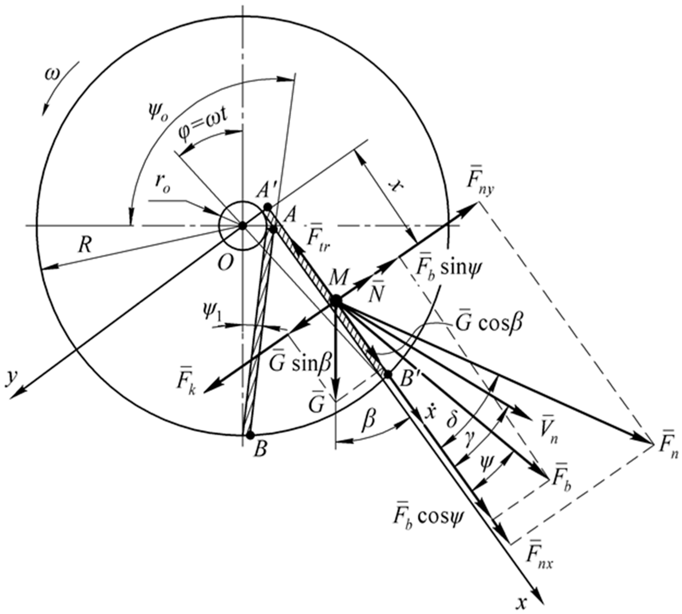
To do this, we first construct an equivalent scheme (
Figure 2). First, consider the cross section of the mechanism for loading beet tops, which in the thrower installation area has a cylindrical casing of radius
R in which a blade thrower is installed on the drive shaft of radius
r0. This thrower has four blades that are rigidly fixed on the drive shaft, and they are located at some angle to the radial direction. When the thrower rotates, each of the blades in turn approaches the loading window area and captures a certain haulm portion that has entered this area. Being on the blade, a portion of the haulm begins forward movement along the blade, simultaneously performing transfer rotation along with the blade. When the blade reaches the area of the unloading window, the dispersed haulm portion is thrown upwards in the direction of the loading nozzle. Further, the movement of the haulm portion, captured by the blade, is carried out in a closed space, which is limited by two adjacent throwing blades and the casing of the thrower. Since the process of the haulm movement along all four blades occurs in the same way, to simplify the equivalent scheme, we will show only this one blade on it. Point
O denotes the rotation center of the considered thrower, and we will limit blade length to segment
AB. The thrower’s rotation direction in the equivalent scheme is shown by an arrow.
First, consider the movement of haulm particle
M along the thrower blade. We choose as the blade’s initial position the time moment when its outer end is located at the lowest point of the possible motion trajectory (point
B). For a certain period of time
t the blade, together with the haulm, moving along it, turn by a certain angle
φ, where
and
is the angular velocity of rotation of the thrower. In this case point
B will move into point
. We will show, on an equivalent scheme, the necessary angular parameters of the considered mechanical system. Let
be the angle between the throwing blade and radius, which is drawn through the rotation axis (point
O) and haulm particle (point
M), moving along the blade surface at an arbitrary time moment
t. We will regard two extreme values of angle
. Staring position
corresponds to the value of angle
when point
M coincides with point
A (or point
). The final position
is the value of angle
in a position when point
M coincides with point
B (or point
in an arbitrary position of the blade). Obviously, during the rotation, the blade angles
and
remain constant. They depend only on the location of the blade relative to the radial direction in the plane of the thrower. Thus, the following inequality
holds for angle
. We will denote
β—the angle between the blade surface and some vertical line at arbitrary time
t. All the angles
,
,
and
β are shown in the equivalent scheme (
Figure 2). As evident from the equivalent scheme, a relationship takes place:
,
,
and
β. To describe the relative motion of a haulm particle along throwing blade
AB, we introduce a flat Cartesian coordinate system
. The axis
is directed along the blade, and the axis
is perpendicular to the plane of this blade, and the axis
passes through the rotation center of thrower (point
O). The origin of the coordinate system
is located at the place where the blade is attached to the drive shaft (point
A). Let us define the necessary geometric relationships between the parameters of the thrower. As can be seen from the equivalent scheme (
Figure 2), we have the following relationships:
and
where
is the current radius of the position of point
M relative to the disk center (point
O) at an arbitrary moment in time
t.
In order to draw up a differential equation for the movement of the considered beet tops particle M along the blade surface, it is necessary to indicate in an equivalent scheme all forces acting on the beet tops particle during its translational movement and to determine their values.
First of all, we distinguish the force of weight of haulm particle
M, which is equal to:
where
is the mass (weight) of haulm particle;
is the gravity acceleration.
The main role in the movement of haulm particles along the thrower blade is played by centrifugal inertia force
, which is equal to:
where
—normal acceleration of particle
M of beet tops in its transfer motion (rotation of the blade around point
O).
Based on the fact that the transfer motion of haulm particle
M is rotational, it is also affected by the Coriolis inertia force
, which is determined from the following expression:
where
—relative speed of beet tops particle movement along thrower blade;
—the Coriolis acceleration.
Also, the friction force
acts upon particle
M during its movement, the value of which will be equal to:
where
—normal reaction of thrower blade surface;
—friction coefficient.
And finally, beet top particle
M is affected by the airflow force
, the component of which
is directed along the axis
and is determined from the expression:
where
—the velocity vector of the airflow, arising from the rotation of the thrower blades;
—the angle between speed vector
and surface of blade;
—a coefficient, which depends on the physical and mechanical beet tops properties.
The force of the action of the airflow along the axis
on particle
M of the haulm will be equal to:
We will find the magnitude of the force of the airflow:
or
After transformations, we obtain:
As shown in the equivalent scheme (
Figure 2), the directions of vector
and the airflow velocity vector
do not match (
). They coincide in direction only at
, that is, at the moment when particle
M of the haulm hits the blade.
When
, we obtain:
That is, .
According to [
7] for air coefficient
k is equal to:
where
is the constant, depending on the shape of the particle and the midsection;
is the midsection;
is the air density.
Taking into Account (14), we obtain:
and
We will assume that the haulm particle hits the thrower blade with an initial speed . The speed of the airflow in the steady mode of rotation of the thrower can be considered constant; that is, , angle between the velocity vector and the plane of the blade will also change insignificantly and fluctuate around a certain value of its average.
Therefore, in the first approximation, we can assume that the component of the airflow velocity .
When analyzing Expression (15), it can be argued that at the moment the particle enters the thrower blade and at the initial stage of the particle movement along the blade, while its relative velocity is rather small, the difference will be quite large (at t = 0: , since ), and therefore force will be maximum or close to the maximum. Therefore, at the moment, when the haulm particle arrives at the blade, the influence of the airflow on the acceleration of the particle along the blade will be most efficient. As the particle moves along the blade and accelerates, the relative velocity x will increase; therefore, difference will decrease, which means that, according to (15), force will also decrease; that is, the influence of the airflow will weaken.
It is quite possible that the difference in some point in time may become negative, and the pressure force of the airflow will turn into a force of resistance to the movement of the particle. However, such an option is possible only at the end of the particle movement along the blade, and, in our opinion, this will not have a significant effect on the velocity of the particle movement.
All the considered forces are shown in the equivalent scheme (
Figure 2). To compile a differential equation for the relative motion of a haulm particle along the thrower blade, we use the basic law of the dynamics of a material point in the following form:
where
is the relative acceleration of particle
M as it moves along axis
;
is the sum of the projections of all forces acting upon particle
M at an arbitrary moment of time
t.
To obtain the right side of Equation (17), we project all the forces acting on the haulm particle onto axis , that is, onto the direction of the relative motion of the said particle.
In this case, the sum of the projections of all forces upon axis
Ax will be equal to:
Let us determine the friction force
of particle
M of the haulm as it moves along the surface of the blade. For this, we determine the normal reaction
of the blade surface under the condition that the sum of the projections of all forces on axis
is equal to zero:
From the last equality we find:
Then, the searched friction force will be equal to:
3. Results and Discussion
Substituting Expression (21) into (18) and the obtained result into Equation (17), we obtain a differential equation for the relative motion of the haulm particle
M along the thrower blade of the following form:
We will express value
through coordinate
using Expression (1), from which we will obtain:
Substituting (2) and (23), as well as relation
into Equation (22), we will have:
We represent Equation (24) in the following form:
Let us transform the right side of Equation (25) to the following form:
or:
We regroup the terms on the right side of Equation (27) as follows:
For abbreviations and convenience of integrating Equation (28), we introduce the following notation:
Taking into account Notation (29), Equation (28) is reduced to the following form:
Equation (30) is a second-order linear differential equation with constant coefficients with the right-hand side [
6]. Let us first find the general solution of the homogeneous equation:
We compose the characteristic equation:
We find the roots of quadratic Equation (32):
and
Then the general solution of Equation (31) has the form:
where
and
are arbitrary constants.
We find a partial solution of the differential Equation (30) in the form of its right side:
where
,
, and
are constant coefficients to be determined.
Substituting Expression (36) and its first and second derivatives into Equation (30), and equating the coefficients of the corresponding functions in the left and right parts of the resulting equation, we obtain a system of linear algebraic equations for the unknowns
,
, and
:
Solving the system of Equation (37), we will have:
Thus, the general solution of Equation (30) has the following form:
where
,
, and
are determined by Formulas (39), (40), and (38), respectively.
The arbitrary constants and are determined from the following initial conditions: at .
Using these initial conditions, we find:
and
So, with the general solution of Equation (30), which satisfies the specified initial conditions, will have the form:
Expression (43) is the law of relative motion of the haulm particle
M along the thrower blade at an arbitrary moment of time
.
For further simulation of the process of movement of the haulm particle M along the cylindrical and rectilinear parts of the casing of the loading mechanism, after it leaves the thrower blade, it is necessary to calculate the relative speed of the particle leaving the thrower blade.
If the length of the blade is given, namely, , then from dependence (43) it is possible to calculate the time for the leaves of the haulm particle to leave the blade at . Such a calculation can be done by means of a PC. By substituting the obtained value of time into Expression (44), one can find the relative value of the haulm particle M leaving the end of the thrower blade.
Let us consider an important partial case when the blades of the thrower are arranged radially. In this case
,
and
. From Expressions (29), we obtain:
The differential Equation (30) for the movement of a haulm particle along the blade in this case is greatly simplified and has the following form:
The general solution of Equation (46), which satisfies the above initial conditions, can be obtained from the general solution (43); however, the coefficients
,
and
, taking into account (45), will already be determined from the following expressions, obtained on the basis of (38)–(40):
So the general solution of the differential Equation (46), when substituting Expressions (47)–(49) into (43), will be written in the following form:
Differentiating Expression (50) with respect to time
, we obtain an expression for the determination of the relative velocity of a haulm particle for the particular case under consideration:
For further simulation of the movement of the haulm particle
M along the cylindrical and rectilinear parts of the casing of the loading mechanism, we need to determine the absolute speed of the haulm particle leaving the end of the thrower blade. Since the forward velocity of the haulm particle
M is directed tangentially to the disk at the point of leaving the blade and is equal in magnitude to
, where
is the radius of the disk, but the angle between the relative and forward velocity vectors is
, then according to the cosine theorem we determine the value of the absolute
of the movement of particle
M of its descent from the disk, which will be equal to:
So, a mathematical model of the movement of a particle of cut sugar beet haulm along the blade of the thrower of the loading mechanism has been built, taking into account the influence of the airflow created by the rotation of the thrower upon the movement of the haulm. As a result, the law of motion of a particle along the blade and the law of change in the relative velocity of its motion as functions of time, as well as the design, kinematic, and dynamic parameters of the thrower blades.
For numerical simulation of the obtained mathematical models on a PC, we have compiled a program for numerical calculations in the MathLAB 9.5 program.
Based on the results of the numerical calculations performed on a PC, graphs of dependences of the absolute speed of the descent of the haulm particle M from the end of the blade upon the length of the blade and upon the angular velocity of rotation of the thrower blades were built. There are also obtained graphical dependences of the relative speed x of the particle movement along the blade on the speed of the airflow at different angular speeds of rotation of the thrower.
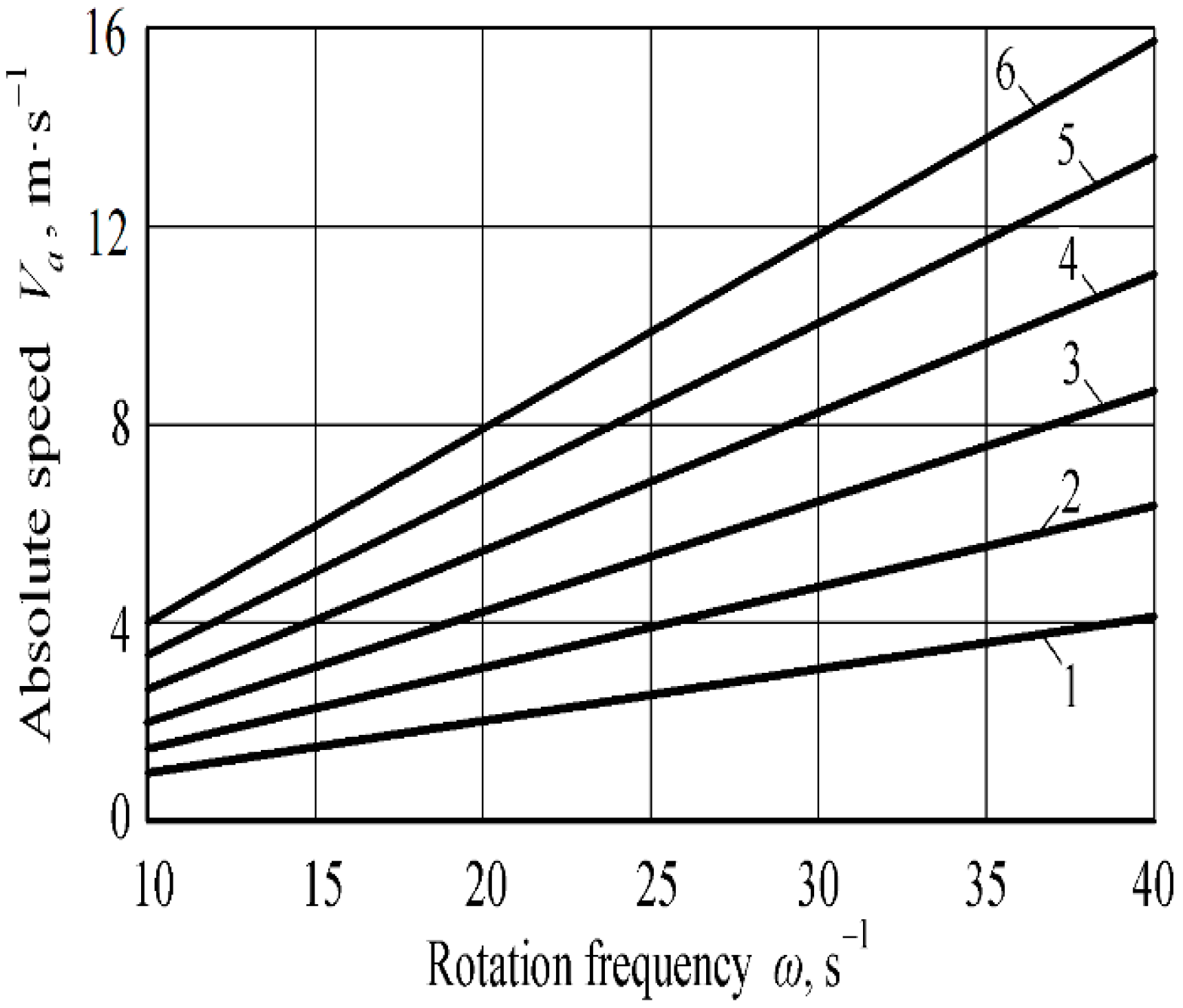
Figure 3 shows the dependence of the absolute speed
of descent of the haulm particle
from the end of the blade, obtained as a result of numerical simulation of the developed mathematical model on a PC, upon the angular velocity
of rotation of the thrower and the length
of the blade.
Analysis of dependencies, presented in
Figure 3, allows one to conclude that an increase in the angular velocity
of rotation of the thrower and the length
of its blade leads to an increase in the absolute speed
of descent of the haulm particle
from the end of the blade. The information shown in
Figure 3 may be used to select the speed of rotation and the length of the blade of the thrower, at which the required absolute speed of the descent of the haulm particle from the end of the blade is achieved with further modeling of its movement along the casing of the loading mechanism of the haulm harvester.
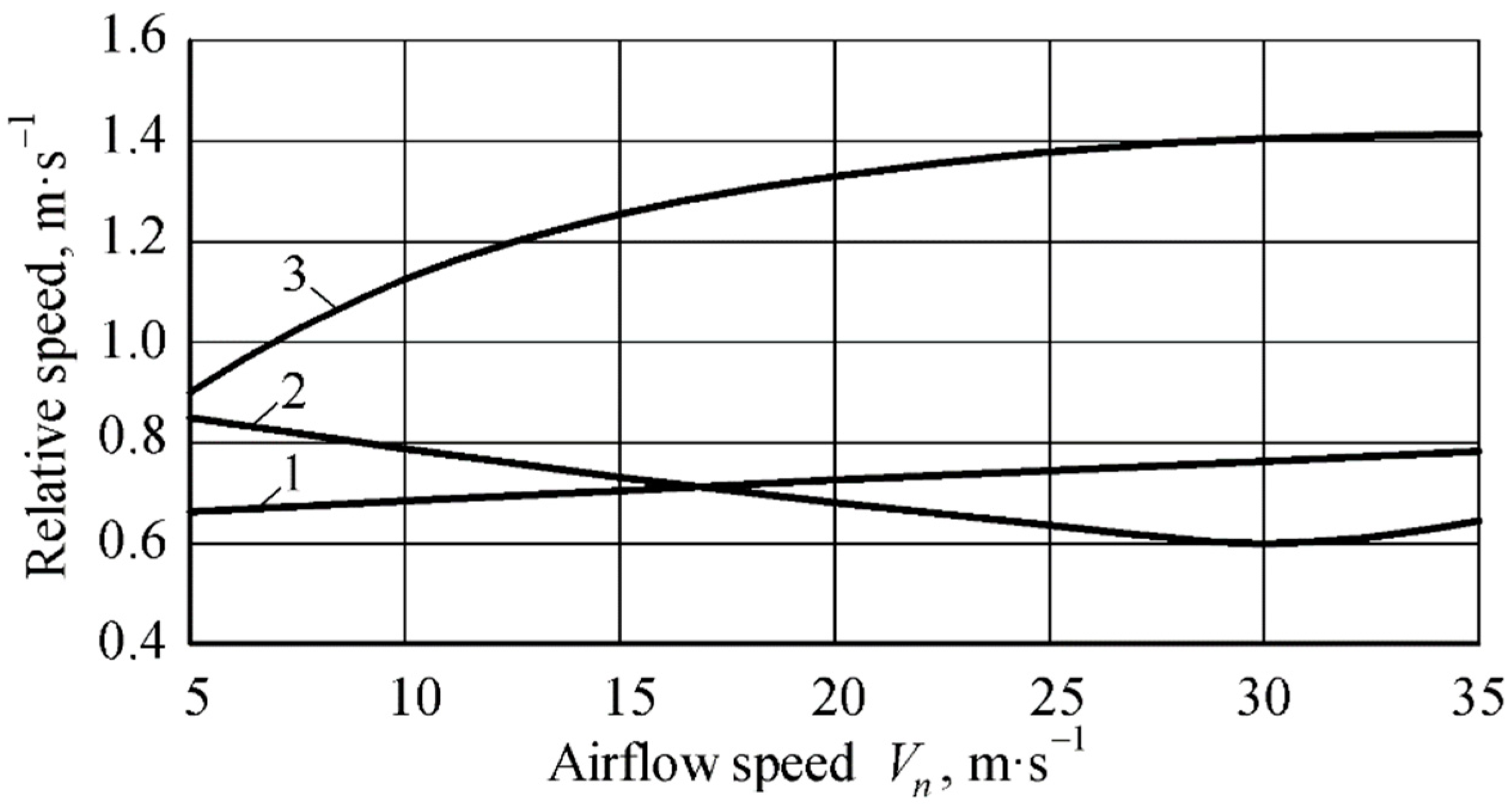
The dependence of the relative velocity of particle
as it moves along the blade upon the velocity of the airflow
at different angular velocity
of rotation of the thrower is shown in
Figure 4.
Analyzing the obtained dependences (Curve 1,
Figure 4), one can say that at a low angular velocity
of rotation of the thrower, an increase in the airflow velocity
from 5 to 35 m·s
−1 leads to a smooth linear increase in the relative velocity of particle
as it moves along the blade from 0.67 up to 0.78 m·s
−1. For a higher angular velocity
of rotation of the thrower (Curve 3), there is a more intense increase in the relative velocity of the haulm particle at an airflow velocity
within a range from 5 to 25 m·s
−1 and approaches a linear law at an airflow velocity of more than 25 m·s
−1.
In addition, the relative velocity varies from 0.9 to 1.4 m·s−1. At an angular velocity of = 15 s−1 (Curve 2), there is a decrease in the relative velocity of particle when moving along the blade at an airflow speed of up to 30 m·s−1, which indicates that the airflow prevents the movement of the haulm particles, and only at an airflow over 30 m·s−1 a gradual increase in the relative velocity of the particle is observed.
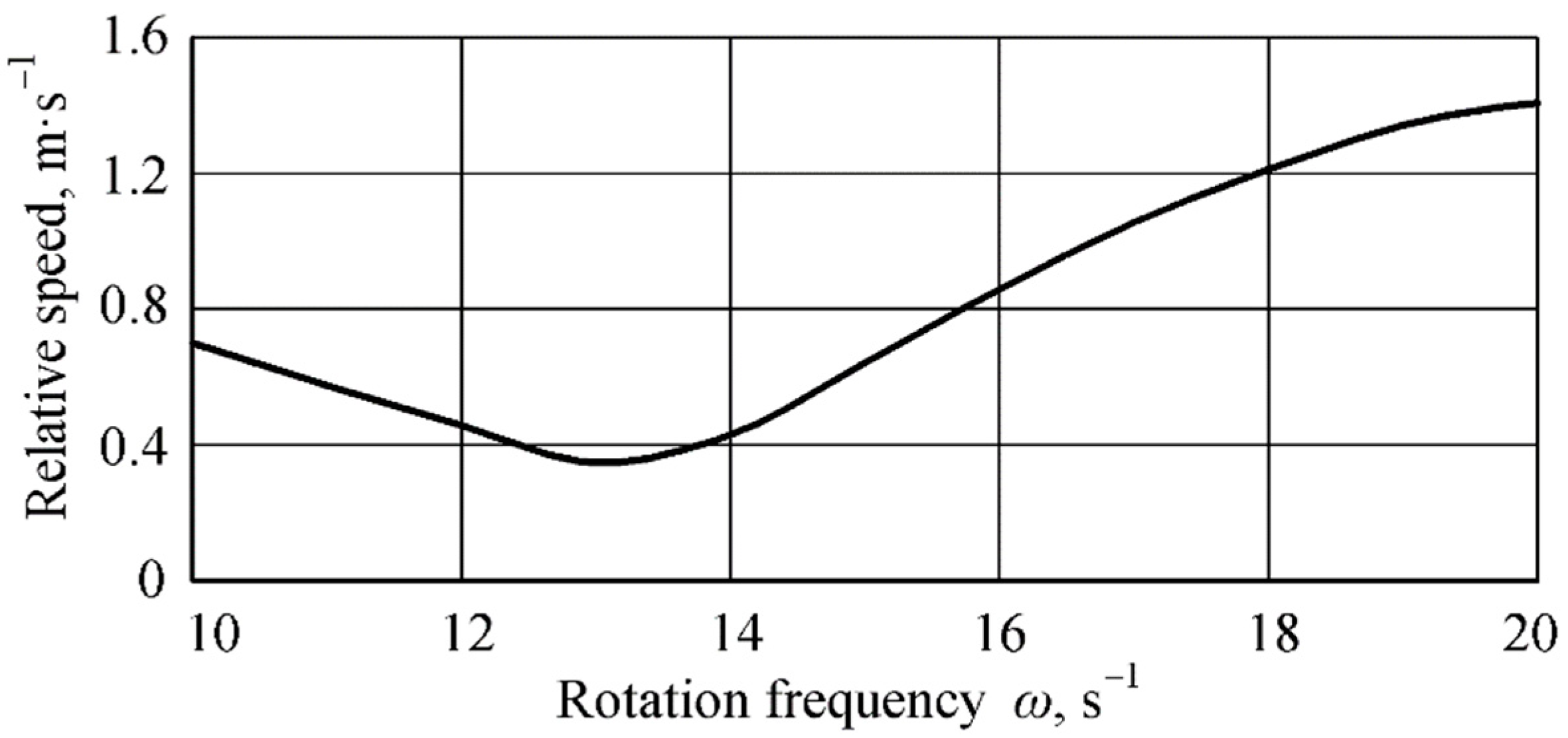
The following shows the dependence (
Figure 5) of the relative velocity
of haulm particle
on the angular velocity
of rotation of the thrower.
The dependence in
Figure 5 shows that in the case of using a thrower with a small blade length (up to 0.15 m) and, despite the high speed
of the airflow, there is a drop in the relative, and as a result, the absolute
speed of haulm particle
when it leaves the blade of the haulm thrower at an angular velocity
, is equal to 10…13 s
−1. Accordingly, for the final selection of the structural and kinematic parameters of the thrower, it is necessary to analyze the output parameters using the developed mathematical model to obtain the highest efficiency and the required absolute speed of the descent of the haulm particle from the blade. This is to ensure its further movement along the surface of the casing of the loading mechanism of the haulm harvester, taking into account the influence of the airflow.
The studies of other authors [
11] previously considered the movement of particles of a technological material along the surfaces of the working parts of agricultural machines and implements. The nature of the change in the kinematic characteristics of the particle under consideration coincides with our results. But, when using the mathematical model that we have developed for the movement of a particle of the tops along the blade of the thrower, more accurate results are obtained since the influence of the air flow and aerodynamic characteristics of the particle are taken into account. This makes it possible to obtain more accurate kinematic characteristics of a particle of tops when considering its further movement inside the casing of the unloading mechanism.
There are also many works [
18,
19,
20] in which elements of the theory of particle movement in the air and liquid flow are considered. Some results of these studies, especially on the straight line sections, confirm the basic laws of changes in the speed of the top particles that we have obtained. But, due to the fact that we have studied a more complex case of acceleration of a particle of the tops on a bladed thrower in the passing air flow and its further vertical movement, we have analyzed the issues of relative and absolute movement in more detail.


 ,
, 