Article

Effect of Damage on the Corrosion Performance of Thermal Spray Aluminium (TSA) Coating in Synthetic Seawater

by
Shiladitya Paul
1,2
1
Materials and Structural Integrity Technology Group, TWI, Cambridge CB21 6AL, UK
2
Materials Innovation Centre, School of Engineering, University of Leicester, Leicester LE1 7RH, UK
Appl. Sci. 2023, 13(2), 1109; https://doi.org/10.3390/app13021109
Submission received: 11 November 2022 / Revised: 5 January 2023 / Accepted: 12 January 2023 / Published: 13 January 2023
(This article belongs to the Special Issue Spray Applications)

Abstract

:
A widely used coating system for corrosion mitigation of offshore steel structures is thermally sprayed aluminium (TSA). Even though these coatings have been used for decades, it is not always clear how they perform in service over long periods, particularly if damaged during installation or in service. To understand the corrosion behaviour of damaged TSA coatings in seawater and their tolerance to levels of damage, TSA coatings (1050 Al) were prepared on carbon steel substrates using wire arc spray and tested in synthetic seawater. Prior to testing, various levels of holidays or damage (~5%, 10%, 15% and 18%) reaching the steel substrate were drilled on the front surface of the coated specimens. Open circuit potential was measured and linear polarization resistance technique was used to calculate the corrosion rate. The work showed that the TSA coatings polarised steel to potentials below −800 mV (Ag/AgCl) at 25 °C, even in the presence of damage or holiday (up to ~18%). The SEM/EDX and XRD data confirmed the presence of brucite and aragonite in the damage region. The presence of damage impacted the short-term corrosion rate at the start, but did not significantly affect the overall corrosion performance of the TSA coatings in 420 days of testing.

1. Introduction

Clean energy sources, such as offshore wind, are key to decarbonise energy production [1]. The material of choice for construction of offshore structures is carbon steel due to its low cost, high strength, machinability and weldability. However, this material is prone to corrosion and associated degradation in offshore environments, hence the need to employ corrosion mitigation methods [2,3]. These corrosion mitigation methods include coatings and/or cathodic protection. Thermally sprayed aluminium (TSA) is a widely used metallic coating system that acts as a barrier when sufficiently thick and offers cathodic protection to immersed offshore steel structures [4].
Several long-term coastal studies beginning in the 1940s, and offshore oil and gas exploration sector experience since the mid-1980s, indicate that TSA provides excellent long-term mitigation of splash and tidal zone corrosion [5,6,7]. As a result, at least one operator has reduced the splash zone corrosion allowance offshore by 3 mm on a number of its projects since 1999 [8]. Outside the oil and gas sector, several offshore wind turbine operators currently specify a coating that includes a first layer of thermally sprayed Zn-15Al (85%Zn-15%Al) for the topside, which is well above the splash zone in the marine atmosphere. Although commercially pure aluminium is a coating considered by the oil and gas sector, one long-term study incorporating tidal, splash and submerged test panels reports that Zn-15Al behaves equally well [7,9].
To date, long-term assessment of TSA coating performance has been in the form of visual examination, reporting evidence of corrosion products (such as rust formation in steel, aluminium oxide/hydroxide on TSA), blistering and dis-bondment, but there are limited data indicating that submerged TSA coatings freely corrode at 2–3 µm per annum in the North Sea [10]. There is also evidence that, when applied correctly, sealants can significantly extend the life of TSA coatings, but the occasional reported failure of sealed coatings implies that further optimisation of this aspect is required [11,12].
The vast majority of TSA coatings are deposited by twin wire arc spraying or wire flame spraying, and their relative merits in terms of coating quality (primarily defined as porosity, oxide content and adhesive strength), process deposition rate and deposit efficiency are well-documented and can be related to coating behaviour [13,14].
It has been predicted that an optimised 200 µm thick TSA coating could provide a service life exceeding 30 years in a splash zone [6]. The work suggested optimizing some key factors such as coating composition, surface preparation, coating application, service application, choice and application of sealer, galvanic exposure condition and environmental impacts. This was based on service experience of TSA applied to Hutton risers and other performance experiences discussed previously. The choice of coating alloy for splash zone or continuously submerged service was noted to be either Al (99.5%) or Al-5Mg. The use of Al-Zn alloys, such as Zn-15Al and Zn-30Al, is likely to increase the cathodic polarizability while decreasing coating lifetime due to the higher dissolution rate of Zn-alloys in seawater [15]. To achieve a good performance coating system, stringent control of surface preparation and application are required [16]. SINTEF reported corrosion rates of 2–3 µm/y after 11 months of exposure in natural seawater in Norway for both 99.5% Al and Al-5Mg. One might argue that this equates to a service life >60 years for a 200 µm TSA coating [6]. In humid industrial or marine atmospheres, corrosion rates of up to 15 µm/y have been reported for thermally sprayed Zn coatings. Hence, in very corrosive environments an unsealed 150 µm thick Zn coating may corrode away in 10 years [17,18].
There are other reports that offer performance data of TSA in different applications. Wolfson [19] reported the successful performance of an arc sprayed TSA coating in a saline-mud environment typical of the deep Gulf of Mexico. The report was based on 4 and 12-month exposure tests conducted in natural Gulf of Mexico seawater (15 °C) and mud (7.7 °C), and included TSA coating performance data in terms of its ability to provide adequate cathodic protection for various amounts of exposed steel. The author concluded the life expectancy of aluminium-silicone sealed TSA coatings of 0.01 inch (254 µm) nominal thickness with up to 5% coating holiday area to be typically greater than 25 years in such saline and mud environments.
Avery [20] conducted a performance review on the application of a TSA coating (99.5% aluminium) on production risers in a subsea environment. The internal temperature of the riser was reported to be about 80–90 °C with a surrounding seawater temperature of about 4–10 °C. The author reported that a 200 µm TSA coating sealed with aluminium-silicone is capable of providing corrosion protection in seawater in excess of 20 years.
Although TSA has been used in the offshore sector for decades, it is not always evident how it performs over the long periods required today by the offshore wind sector, particularly in the presence of damage that might occur during installation or in service. Literature data suggest that the focus thus far has been on the performance evaluation of TSA coatings under seawater immersion service. However, published work on TSA with damage has been limited to exploring the effect of single, small-scale damage on the corrosion performance [21]. The damage has been restricted in these studies largely to ~5% of coating area. Damage in service is not limited to 5% and the nature of damage during transport, installation or service is not restricted to a single holiday. Detailed experimental study on the effect of multiple damage/holiday or large-scale damage, such as 18–20% exposed area, has not been carried out. Furthermore, the vast majority of published information on coatings with damage only refer to short-term tests [22]. Thus, long-term performance data on damaged TSA would benefit the offshore energy community. As previously mentioned, the limited studies with damage in TSA restricted the damage to 5%. In limited cases where a larger damage area was used [23], detailed systematic study was not carried out to fully explore the corrosion or protection mechanism.
Detailed study on the corrosion mechanism of thermal spray coatings, including the use of organic sealants, have been reported [24]. Some work on the corrosion mechanism in the cathodic region of exposed steel provided useful information for situations with one ‘damage’ area of 5% [25]. The corrosion products on the TSA and the defect area vary and can provide valuable information on the corrosion mechanism [26]. Laboratory and field trials have provided useful information on the products of the corrosion process [27,28,29,30,31,32]. However, as indicated earlier these reports only provide information on coatings that fully cover the steel, or in the case of intentional ‘damage’, only provide data with one single area of exposed steel.
Even the modelling work on TSA with damage has focused on simple ‘single’ damage area [33]. The lack of detailed work on the effect of damage was also highlighted in the review on TSA by Syrek-Gerstenkorn et al. [4]. Thus, understanding the mechanisms that govern long-term performance of TSA, especially when damaged, is important. The corrosion mechanism leading to loss coating is a key aspect. However, deposits formed on exposed steel may also play a significant role and impact the corrosion rate. These deposits formed on the damage areas need to be evaluated in terms of phases, microstructure and pore architecture to appreciate their impact on the corrosion process.
The work presented in this paper addresses some of the knowledge gaps presented above. The aim of this work is to study the corrosion behaviour of damaged thermally sprayed aluminium (TSA) coatings in synthetic seawater and understand the impact of increasing levels of damage on performance. The words ‘damage’ or ‘holiday’ have been used in this paper to mean areas where the TSA has been removed to expose steel substrate.

2. Materials and Methods

2.1. Materials

The substrate used in this work was 6 mm thick C-Mn steel plate conforming to BS EN10025-2 grade S355J2+N(2004). This was cut into ~43 mm × 40 mm coupons for electrochemical monitoring during exposure. The coating material used for this work was 2.3 mm diameter commercially ‘pure’ aluminium (99.5% Al) wire conforming to aluminium grade 1050/1350. These grades are acceptable according to NORSOK M501 [34] and ISO 14919 [35]. The nominal compositions of the substrate and wire consumable are given in Table 1.

2.2. Specimen Preparation and Coating Production

The edges of the substrates were rounded off prior to further preparation. Prior to coating, the substrates were degreased and then prepared by blasting (at 80 psi) with NK36 alumina abrasive blasting grit to give the desired rough surface. The steel substrates were prepared to Sa3 in accordance with ISO 8501-1 (Blast-cleaning to visually clean steel, [36]).
Coatings were produced using a Metallisation ARC140 (Metallisation Limited, Dudley, UK) twin wire arc spraying (TWAS) system. The spray gun was mounted on a programmable 6-axis thermal spray robot.
Coatings produced by TWAS were applied in accordance with the equipment manufacturer’s recommended spray parameters (i.e., current, arc voltage, stand-off distance) to attain a nominal coating thickness of 0.3 mm. A summary of the spraying parameters used is provided in Table 2.

2.3. Corrosion Testing

2.3.1. Sample Preparation

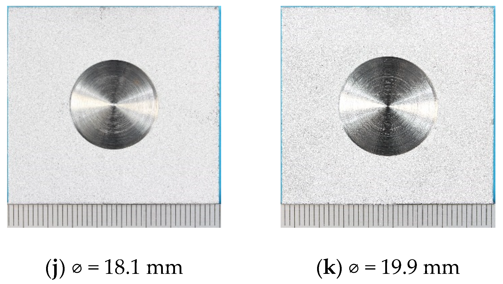
The TSA-coated specimens were air blasted to clean the surface. Holidays (damage) amounting to ~5%, 10%, 15% and 18% of the coating surface area were drilled into the coated surface of the specimens to expose the underlying steel substrate (Figure 1).
Lacquer was applied to the back and sides of the specimens to define the test area and to stop unwanted galvanic corrosion of the TSA coating with the surfaces not TSA-coated. A summary of the specimens used for testing is presented in Table 3.

2.3.2. Electrochemical Monitoring

A Gill ACM potentiostat (ACM Instruments, Manchester, UK) was used to monitor the potential of the specimens at open circuit potential (OCP). Linear polarisation resistance (LPR) technique was used to measure the polarisation resistance and calculate the corrosion rate. The corrosion rate was calculated from LPR data by using the Stern and Geary [37] approach (later modified by Stern in 1958, [38]).
Electrical connections for electrochemical monitoring were made on the side of the specimens. A Pt/Ti counter electrode was placed in front of the specimens. In all cases, Ag/AgCl (saturated KCl) reference electrodes were used; the potential values reported in this paper are with respect to this reference unless otherwise stated.
Once the specimens were placed in a reactor tank, the reactor was filled with ASTM D1141 synthetic seawater without the heavy metals [39]. The seawater tank was heated to 25 °C and electrochemical monitoring was carried out. To ensure uniform temperature inside the tank, the seawater was circulated slowly using a pump.

2.4. Characterisation

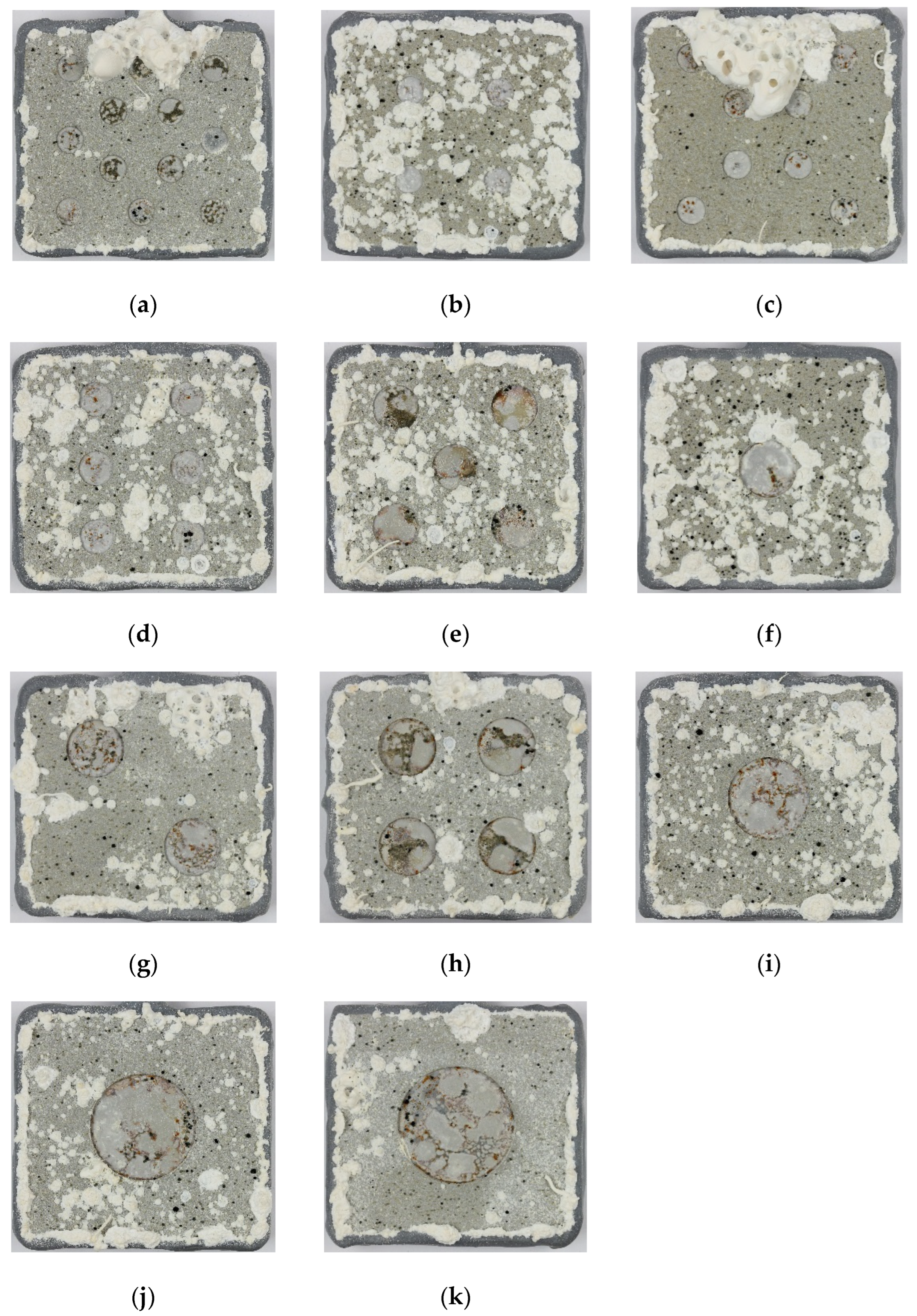
The specimens were photographed after testing (Figure 2). In some cases, the specimens were sectioned and cold-mounted for microstructural analysis using a light microscope, and SEM with EDX. For SEM examination, the specimens were sputter coated with Au. To find the phases present, X-ray diffraction (XRD) studies were carried out on some specimens, especially those with copious deposits. Detailed study of the deposits in the holiday (damage) was also carried out in selected cases.

3. Results

3.1. Open Circuit Potential (OCP)

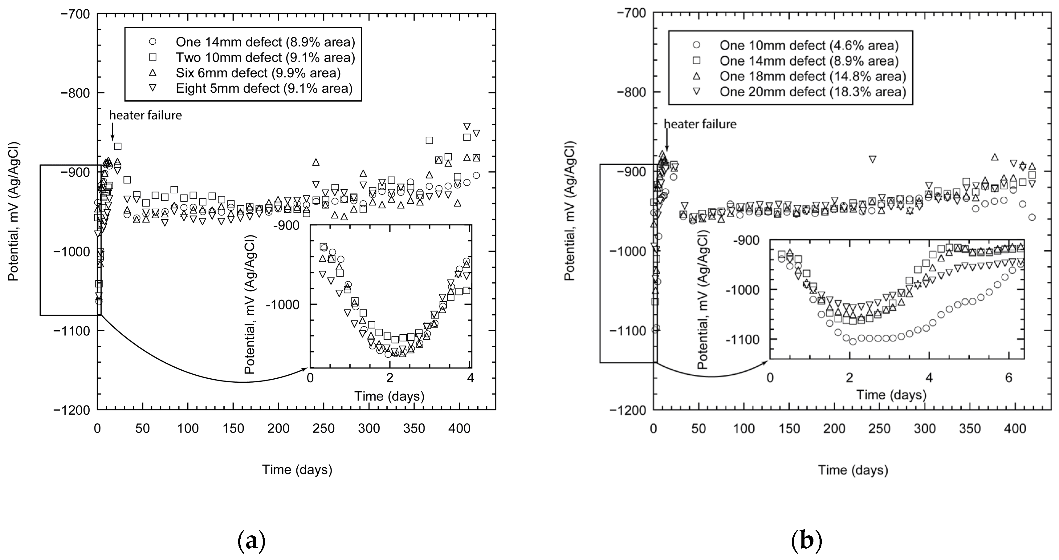
The TSA coating polarised the specimens below the potential of carbon steel. In the case of specimens with one holiday (the total damaged area varied), the potentials (or OCP) reached values close to −900 mV not too long after immersion (within a few hours), Figure 3a. The inset shows the variation in the potential as a function of damage area. It would appear that the specimen with the least area of damage (4.6%) shows the most negative potential. These data, however, represent the initial transients; soon the potentials approach more stable values between −940 to −960 mV. The specimen with the smallest damage area remained more active (with a more negative potential) than the rest in the initial stages, but as time progressed its activity declined further and the potentials became very similar.
When similar experiments were carried out on specimens with different damage numbers (with approximately the same total damage area), the results were similar (Figure 3b). The specimens were polarised to values more negative than the protective potential of steel (−800 mV). The potential (OCP) of the specimens initially became more negative within the first few hours of testing. The inset shows that the values are close to −1060 mV within 2 days of exposure (Figure 3b). These values become less negative with time and reach more stable values between −940 to −960 mV. The potential reached values of approximately −920 mV after 420 days of exposure.

3.2. Corrosion Rate

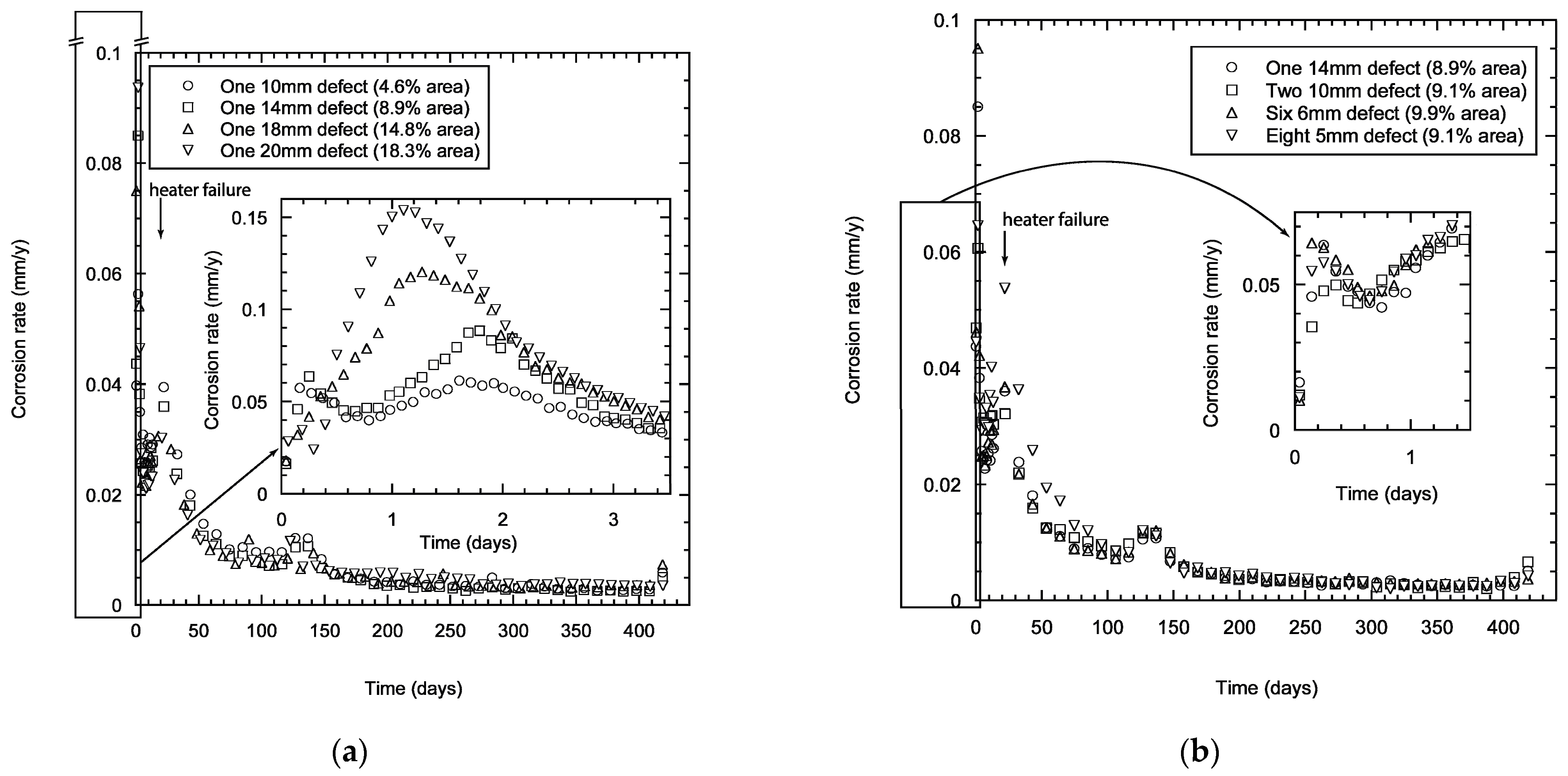
The corrosion rates for TSA specimens with one damage (damage area 4.6–18.3%) showed scatter in the early stages of immersion with values in the range of 0.05–0.15 mm/year in the initial stages (Figure 4a). However, the scatter lessened with time of exposure and the corrosion rate decreased reaching values <0.02 mm/year after a month. The scatter in the data was reduced significantly after a few months of exposure and the specimens reached calculated corrosion rates <0.005 mm/year after testing for 250 days. The corrosion rate values obtained in the first few days clearly indicate that the damage area has some effect, primarily due to the dependence of the corrosion kinetics on the relative areas of anode and cathode. Unsurprisingly, the specimen with larger damage area (18.3%) shows a higher corrosion rate of aluminium compared to the specimen with smaller damage area (4.6%).
The calculated corrosion rate for specimens with different number and size of damage (with same estimated total area ~9–10%) showed similar trends (Figure 4b). The disparity in the calculated corrosion rate was not as substantial as with the specimens with different damage areas. However, the calculated corrosion rates were not too different and the values reduce to <0.01 mm/y within 3 months of testing. The corrosion processes stabilised with time and this was reflected in decreased corrosion rates. The values reached ~0.005 mm/year after 250 days of testing (Figure 4b). The initial reduction in the corrosion rate at the start was expected to be due to the presence of a passive air-formed oxide film. This film subsequently dissolves in Cl- solution, thus increasing the corrosion rate. A further reduction in corrosion rate occurred when aluminium oxide/hydroxide forms on the TSA coating and calcareous deposits predominantly form on the damage area.
The change in the trend observed at a couple of time points was due to failure in the heater. However, the laboratory where the test was carried out was at 21 °C. The change in the corrosion rate to values below 0.01 mm/y after a few months and below 0.005 mm/y after a year of exposure shows that the thermally sprayed coating was being consumed at a very low rate after the initial period, and the reduction of the corrosion rate was probably due to the formation of protective aluminium oxide/hydroxide and associated calcareous deposits (predominantly in the damage area).

3.3. Microstructure and Phases

3.3.1. Microstructure

All the TSA-coated steel specimens were tested at OCP in synthetic seawater (ASTM D1141). The specimens had holidays/damage exposing steel to ~5, 10, 15 and 18% of the geometric surface area. After testing, the holiday/damage region in all specimens were covered with a grey/white deposit. The surface of the TSA coating also had a deposit, but of a slightly different colour (Figure 2).
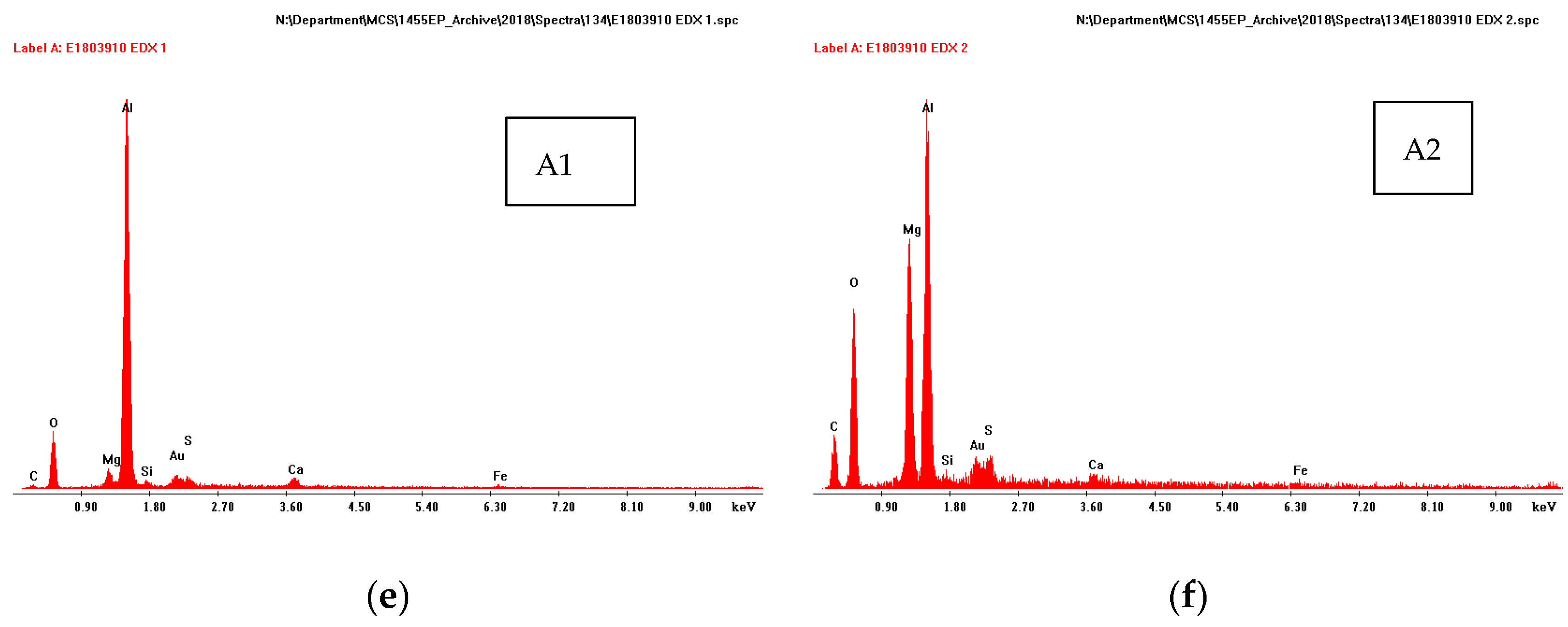
The cross-sections of specimens showed a deposit on steel covering the entire holiday. An example of the specimen with one damage (18.3% area) is shown in Figure 5a. The deposit on the steel surface had a two-layer structure, comprising a thin Mg-containing layer adjacent to steel and a thicker Ca-containing layer above. It is evident from EDX analysis that the deposit formed adjacent to the substrate contained Mg and O, while the layer further away from the substrate had Ca, O and C. No Mg was found in this outer layer away from the substrate (Figure 5b,c).
A thin deposit (~10 µm) was also seen on top of the thermal spray layer (Figure 5d). This was seen in all specimens (irrespective of the damage size or area). The deposit on top of the thermal spray Al layer had multiple layers. The layer closest to Al had Al and O, the layer above to it had Mg and O in addition to Al (Figure 5e,f).
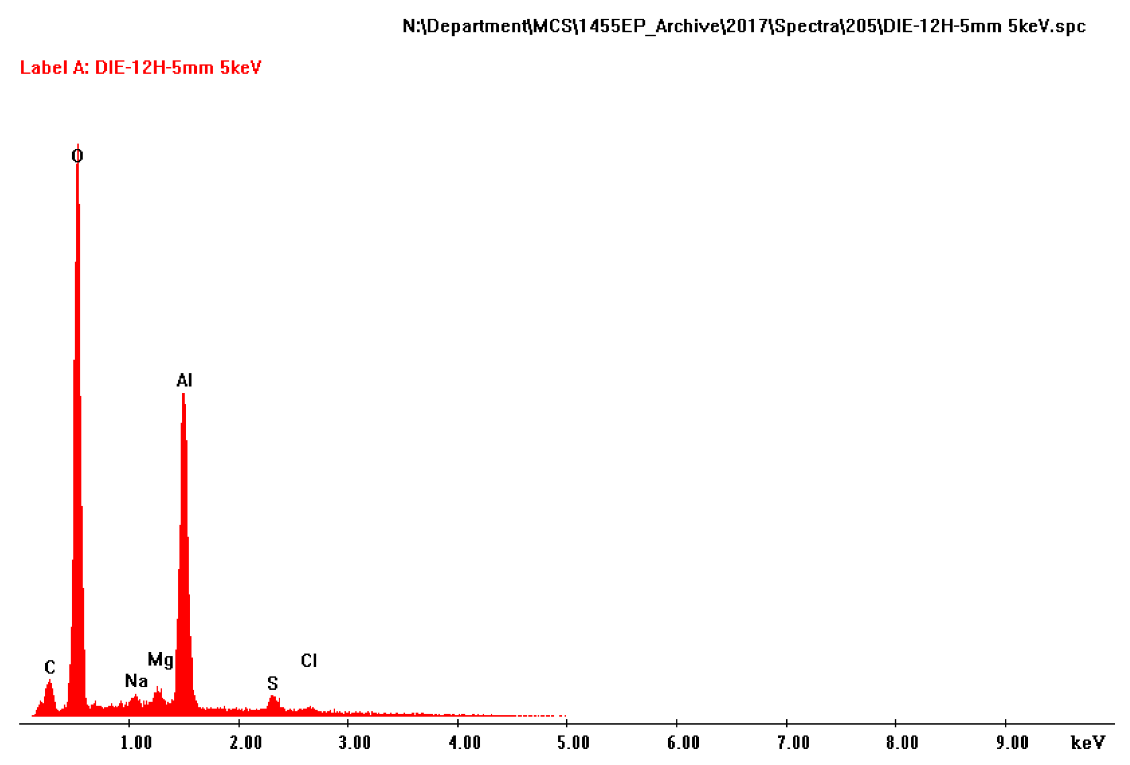
The amount of deposit on the TSA surface varied, but no correlation was found between the area, size or the number of damage and the amount of deposit on TSA. The white deposit on the surface of TSA was predominantly composed of Al and O (Figure 6). Some trace elements were also noted in the EDX pattern, but these are consistent with the constituents of synthetic seawater or the mounting compounds.

3.3.2. Crystallographic Phases

X-ray diffraction (XRD) was used to identify the crystalline phases present in the deposits formed in the holiday region and on the surface of the TSA coatings.
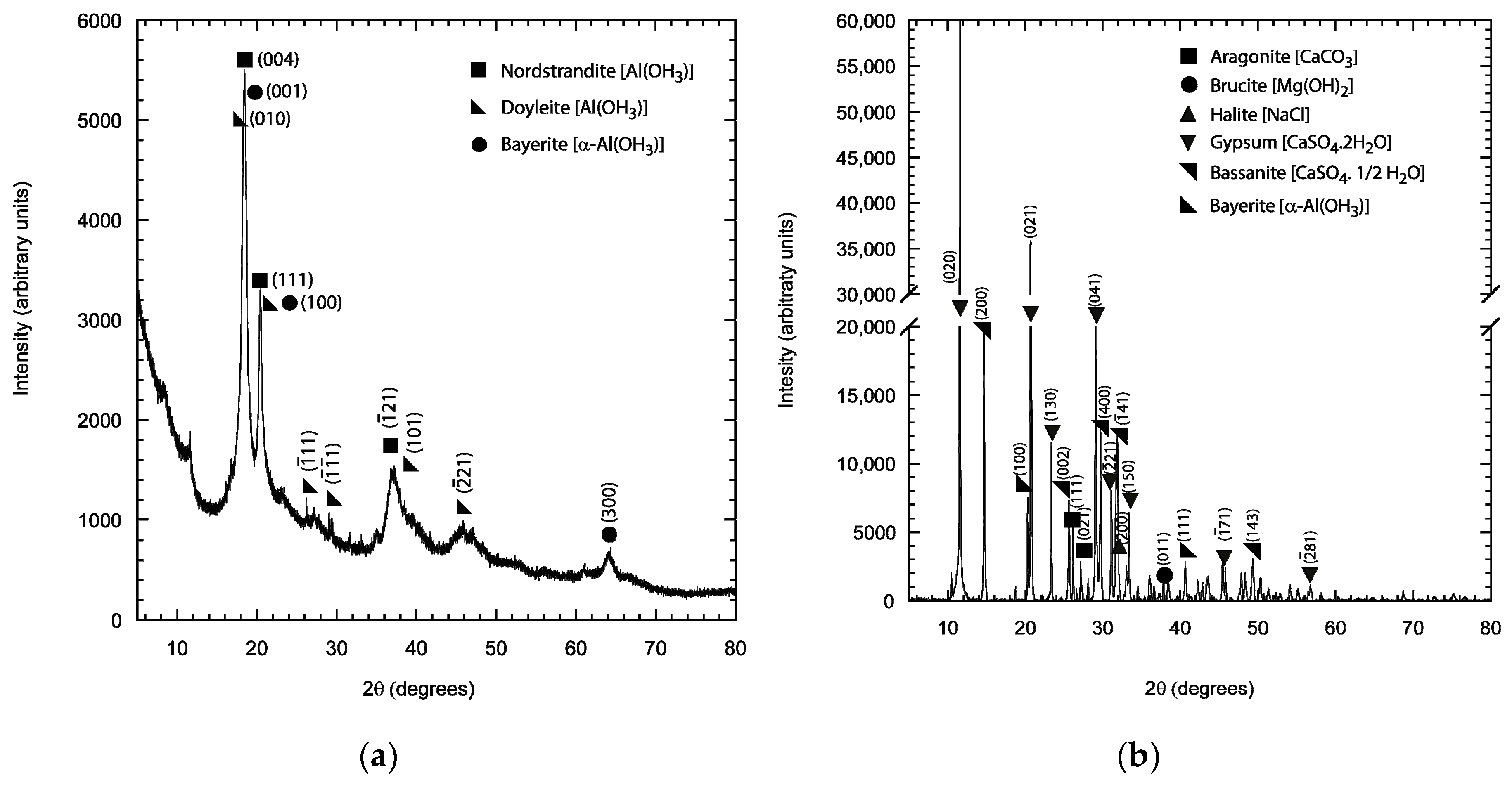
All the hydrated oxides/hydroxides of Al have the formula Al(OH)3, but they vary in the crystallographic polymorphs or polytypes, i.e., Bayerite, Doyelite and Norstrandite, which can be generally named as Gibbsite. Bayerite is monoclinic, whereas Doyleite and Nordstrandite are triclinic.
From the EDX analysis it was apparent that the two elements that comprised the majority of the deposit were Mg and Ca. The composition of the deposit did not change significantly with the area of damage. To understand the corrosion mechanism on exposed steel and TSA, XRD was carried out on the deposit formed on the TSA surface and the deposit found in the damage/holiday region on top of steel.
The deposit collected from the TSA surface was predominantly Gibbsitic, with some indication of the presence of amorphous hydrated oxides of aluminium. The crystalline peaks correspond to Norstrandite, Doyelite and Bayerite (Figure 7a).
The deposit collected from the holiday/damage region showed Aragonite and Brucite phases present, as expected (Figure 7b). Some peaks of Gypsum were also found along with that of Bayerite, Bassanite and Halite (Figure 7b).

4. Discussion

4.1. Corrosion Performance

The equilibrium potential assumed by the metal (or the coating system) in the absence of any current flowing through the circuit is called the open circuit potential (OCP) or the rest potential. When the potential of a material in solution is forced away from OCP by using a potentiostat, it is referred to as polarising the material. The response of the material, current, is measured as it is polarised. This gives the potential versus current curve, which approximates to a straight line near the OCP. The slope of this line is called the polarisation resistance (Rp). Polarisation resistance is inversely proportional to the corrosion current and hence the corrosion rate.
It is generally recommended to allow sufficient time for the OCP to stabilise before beginning the electrochemical test. A stable OCP is an indication that the system being studied has reached a ‘steady state’. However, in many cases the corrosion reaction rates are such that it may take many hours/days before the so called ‘steady state’ is reached. This might explain the fluctuations in the potentials of some of the samples tested. The potentials attained by the samples (with different damage areas) after a few months are similar. In the absence of a thermally sprayed layer, the open circuit potential would assume the value of the carbon steel substrate. Thus, the presence of TSA polarises the entire specimen to potentials well below the so called protective potential of approximately −800 mV, and while doing so the TSA gets preferentially consumed.
Although polarisation resistance gives an indication of possible corrosion performance, the corrosion rate is related to other parameters (like the Tafel slopes) which are dependent on the material and the environment. As the nature of the surface governs the polarisation resistance, these values can change depending on the surface properties. For TSA coatings with damage, the corrosion rate values of TSA are also governed by the area of steel exposed. However, in the corrosion rate data this difference was only noticed in the first week of testing, indicating a reduction in the area of steel exposed with time. This ‘reduction’ is related to the deposition of calcareous matter on the steel surface. Further, the surface of TSA had some corrosion products which also increased the polarisation resistance or decreased corrosion rate.
The reduction in the corrosion rate with time of exposure, even when damaged, is an added benefit for the use of TSA in offshore service. The initial corrosion rate might be a bit higher when holidays are present, where the exposed steel is acting as a cathode and causing accelerated corrosion of the anodic TSA. However, the deposition of calcareous matter reduces the effective area of exposed steel. The nature of the calcareous matter, when present, governs the intensity of galvanic interaction between the TSA and the steel. The ionic path between the steel and the TSA is at least partially blocked by the calcareous matter. The conductivity of the calcareous matter-electrolyte combination somewhat determines the galvanic interaction. Thus, the calcareous matter plays a vital role is protecting the TSA-coated steel when damaged prior to service.

4.2. Design Life of Steel Structures Coated with TSA

The corrosion rate of unprotected C-Mn steel in seawater is reported to be ~0.1 to 0.5 mm/y [40]. Although this value depends on various factors such as temperature, salinity, agitation, wet and dry conditions etc., it nonetheless gives a good guide. The presence of a thermally sprayed anodic material, such as a TSA coating, will protect the steel while the coating is being preferentially consumed. Little or no measurable corrosion of the C-Mn steel plate is likely to occur in the absence of holiday or damage. Even when a holiday is present, the TSA coating is likely to protect the steel provided the holiday is in electrical and electrolytic contact with the TSA. Even when no apparent holiday is present, the thermal spray process produces a coating with porosity. This porosity, if surface connected, causes precipitation of calcareous material on the surface of exposed steel. The calcareous deposits plug the pores close to the steel surface causing a sealing effect. Similar sealing effect is also expected due to the generation of Al corrosion products on the pore walls. The test data presented in this paper showed that the TSA coatings provided sufficient protection to mitigate corrosion of the C-Mn steel substrate during immersion in artificial seawater, with the thermal spray layer acting both as a barrier and sacrificial coating.
Electrochemical measurements during immersion showed that the calculated corrosion rate of TSA was initially high at ~0.1 mm/y, in all the coated samples, but decreased significantly after 300 days to ~0.005 mm/y, as shown in Figure 4. The initial high corrosion rate was likely to correspond to exposure of the active as-sprayed coating and the steady reduction of the corrosion rate due to the formation of corrosion products and associated calcareous deposits. This change in corrosion rate corresponded to a steady increase in potential of the coated samples from approximately −1100 mV to −900 mV, which corresponds to the coatings becoming less active. Nevertheless, potentials were maintained below 800 mV (Ag/AgCl) for all cases for the entire duration of the tests, which is generally considered to be the threshold for the cathodic protection of C-Mn steel in seawater immersion.
Estimates of the loss of coating thickness are difficult to obtain from physical thickness measurements due to the build-up of corrosion product and calcareous deposit which fill the pores present in the thermal spray coatings and the relatively small losses of material during the test periods. However, from electrochemical measurements during alternate immersion, corrosion rates <0.005 mm/y were calculated after 300 days of exposure. For the sake of simplicity, if we assume that the TSA consumption occurs at a rate of 0.005 mm/y over the nominal coating thickness of 0.3 mm, one would estimate coating service life to be ~60 years. However, one must note that although the corrosion rates are calculated and presented in units such as mm/y, is not constant over the material’s lifetime. In the case of TSA in service, the corrosion rate is likely to change further as the calcareous deposits form or if mechanical damage of the coating occurs. Realistically, if a safety factor of two is assumed, a coating life exceeding 30 years can be expected using unsealed Al with holidays.
The values of estimated coating life in the previous paragraphs are based on constant immersion in quiescent laboratory conditions and thus are not entirely representative of real life immersed zones. The seawater velocity has a bearing on the corrosion rate. However, they give a good indication of corrosion performance in seawater immersion conditions. In other areas of an offshore structure, such as the splash zone or the tidal zone, the environmental conditions are different. In such environments, the seawater splash or alternate immersion combined with temperature fluctuations, UV radiation, biofouling, etc. provide different service conditions to the ones presented in this paper. Hence, the coating consumption rate in real service conditions will be somewhat different. Nonetheless, the coating corrosion life values presented in this paper for immersion service give some indication of the performance and could be considered a rough estimate.

4.3. Limitations and Further Development

The work presented in this paper focused on the corrosion performance of arc-sprayed aluminium with predefined circular damaged areas. The damaged areas had coatings completely removed to expose the underlying steel substrate. The geometry of the damaged area was circular in nature. Although the size and the number of such ‘damaged areas’ varied, the geometry still remained circular. It was also assumed that the production of such damaged areas did not result in any changes to the kinetics or nature of the oxide formed on the TSA surface. However, it must be noted that the concentration of electronic defects have a bearing on the nature of Al2O3 produced [41,42]. It might also influence the way in which aluminium deteriorates [43]. Nonetheless, as the ‘damages’ were substantial compared to the defects that might have been generated during the sample production phase, it is fair to assume that the impact of electronic defects would be significantly less and the nature of the response would be dominated by mechanical ‘damages’ [43].
The electrochemical monitoring presented in the paper is not novel. Electrochemical techniques such as OCP, LPR and Tafel analysis are regularly carried out to ascertain the corrosion behaviour on a regular basis. The intension of the work was not to develop new methods of assessment or coating production, but to provide detailed experimental data on arc-sprayed TSA. Such detailed work on the performance of damaged coatings in seawater has not been previously reported in open literature. However, further development of electrochemical monitoring methods would be beneficial for better understanding of the anodic and cathodic reactions. Some progress has been made to understand the cathodic reaction by using zero resistance ammeter (ZRA) between the steel and the TSA [25]. EIS also allows better understanding the corrosion mechanism once a suitable electrical equivalent model has been identified [44]. Modelling work is also considered beneficial in theoretically looking at the possible mechanisms [33]. It also allows one to carry out ‘simulated’ experiments without the expense and time constraints. These developments are likely to improve our ability to better understand the mechanisms that govern the performance of TSA in service.

5. Conclusions

The following conclusions can be drawn from the work presented in this paper:
  • TSA has the ability to polarise coated steel to potentials more negative than −800 mV vs. Ag/AgCl (saturated KCl) at 25 °C. This behaviour was observed even when a damage or holiday (up to ~18%) was present.
  • The calculated corrosion rates were found to be below 0.01 mm/year after 3 months of immersion testing even when a holiday (up to ~18%) was present in TSA-coated steel specimens. The extrapolated long-term TSA coating corrosion rate was found to be <0.005 mm/year.
  • Deposits were found in the damage region of TSA-coated steel. The deposits comprised a layer of brucite [(Mg(OH)2] close to the steel substrate and a layer of aragonite (CaCO3) away from the substrate. This layer of deposits formed on the cathodically polarised steel surface reduced the exposed steel (effective cathode) area to some extent. This possibly resulted in lowering the corrosion rate of TSA.
  • Natural seawater contain salts of Mg and Ca. These dissolved salts are responsible for the formation of calcareous deposits on cathodically polarised surfaces. Therefore, the presence of these salts are important in the electrolyte when simulating seawater in the laboratory. Although 3.5 wt% NaCl solution has the same chloride equivalent as seawater, it should not be used in the laboratory as a substitute for natural or synthetic seawater to evaluate marine corrosion performance of TSA coatings.

Funding

This research was funded by TWI’s Industrial Members via the Core Research Programme (CRP). The Author would also like to thank MDPI for full APC waiver.

Institutional Review Board Statement

Not applicable.

Informed Consent Statement

Not applicable.

Data Availability Statement

Not applicable.

Acknowledgments

The author would like to thank Mike Bennett, Catherine Leahy, Sheila Stevens, Ashley Spencer and Sally Day for their technical assistance.

Conflicts of Interest

The author declares no conflict of interest. The funder had no role in the design of the study; in the collection, analyses, or interpretation of data; in the writing of the manuscript; or in the decision to publish the results.

References

  1. Sherman, P.; Chen, X.; McElroy, M. Offshore wind: An opportunity for cost-competitive decarbonization of China’s energy economy. Sci. Adv. 2020, 6, eaax9571. [Google Scholar] [CrossRef] [PubMed] [Green Version]
  2. Refait, P.; Grolleau, A.-M.; Jeannin, M.; Rémazeilles, C.; Sabot, R. Corrosion of Carbon Steel in Marine Environments: Role of the Corrosion Product Layer. Corros. Mater. Degrad. 2020, 1, 198–218. [Google Scholar] [CrossRef]
  3. Alcántara, J.; de la Fuente, D.; Chico, B.; Simancas, J.; Díaz, I.; Morcillo, M. Marine Atmospheric Corrosion of Carbon Steel: A Review. Materials 2017, 10, 406. [Google Scholar] [CrossRef] [PubMed] [Green Version]
  4. Syrek-Gerstenkorn, B.; Paul, S.; Davenport, A.J. Sacrificial Thermally Sprayed Aluminium Coatings for Marine Environments: A Review. Coatings 2020, 10, 267. [Google Scholar] [CrossRef] [Green Version]
  5. Bland, J. Corrosion Tests of Flame Sprayed Coated Steel: 19-Year Report; American Welding Society (AWS): Miami, FL, USA, 1974. [Google Scholar]
  6. Fischer, K.P.; Thomason, W.H.; Rosbrook, T.; Murali, J. Performance history of thermally sprayed coatings in offshore service. Mater Perform. 1995, 34, 27–35. [Google Scholar]
  7. Kuroda, S.; Kawakita, J.; Takemoto, M. An 18-year exposure test of thermal-sprayed Zn, Al, Zn-Al coatings in marine environment. Corrosion 2006, 62, 635–647. [Google Scholar] [CrossRef]
  8. Tiong, D.K.K.; Pit, H. Experiences on “Thermal Spray Aluminium (TSA)” Coating on Offshore Structures; NACE Corrosion: New Orleans, LA, USA, 2004; p. 04022. [Google Scholar]
  9. Guyonvarch, A.; Gras, J.M. Corrosion en ambiances naturelles: Comportement des métallisations et peintures utilisées comme protection des aciers non allies. Mater. Tech. 1990, 78, 33–40. (In French) [Google Scholar] [CrossRef]
  10. Gartland, P.O.; Eggen, T.G. Thermal sprayed aluminium coatings in seawater with and without cathodic protection. In Marine Corrosion of Stainless Steels: Chlorination and Microbial Effects; European Federation of Corrosion: London, UK, 1993; WP 10 Publication; p. 195. [Google Scholar]
  11. Knudsen, O.; Rogne, T.; Rossland, T. Rapid Degradation of Painted TSA; NACE Corrosion: New Orleans, LA, USA, 2004; p. 04023. [Google Scholar]
  12. Thomason, W.H.; Olsen, S.; Haugen, T.; Fischer, K. Deterioration of Thermal Sprayed Aluminium Coatings on Hot Risers Due to Thermal Cycling; NACE Corrosion: New Orleans, LA, USA, 2004; p. 04021. [Google Scholar]
  13. Shrestha, S.; Sturgeon, A. Characteristics and Electrochemical Behaviour of Thermal Sprayed Aluminium (TSA) Coatings Prepared by Various Wire Thermal Spray Processes; EUROCORR: Lisbon, Portugal, 2005. [Google Scholar]
  14. Harvey, M.D.F.; Shrestha, S.; Sturgeon, A.J. Coatings for Offshore Applications by High Velocity Wire Flame Spraying; NACE Corrosion: Houston, TX, USA, 2005; p. 05011. [Google Scholar]
  15. Kweon, Y.G.; Coddet, C. Blistering mechanisms of thermally sprayed zinc and zinc-based coatings in seawater. Corrosion 1992, 48, 660–665. [Google Scholar] [CrossRef]
  16. ANSI/AWS C2.18-93R; Guide for the Protection of Steel with Thermal Sprayed Coatings of Aluminium and Zinc and Their Alloys and Composites. ANSI: Washington, DC, USA, 1993.
  17. Knudsen, O.O. Coating System for Long Lifetime—Thermally Sprayed Duplex Systems; SINTEF Report No. A14189: Trondheim, Norway, 2010; ISBN 978-82-14-04760-8. [Google Scholar]
  18. ISO2063-1; Thermal Spraying—Zinc, Aluminium and Their Alloys—Part 1: Design Considerations and Quality Requirements for Corrosion Protection Systems. ISO: Geneva, Switzerland, 2019.
  19. Wolfson, S.L. Corrosion control of subsea piping systems using thermal sprayed aluminium coatings. Mater Perform. 1996, 35, 29–37. [Google Scholar]
  20. Avery, R. Review of the Long Term Performance of Thermal Sprayed Aluminium in a Subsea Environment; Document Ref. ROS 103, Rev 0; Rosbrook Associates Ltd.: Edinburgh, UK, 1999. [Google Scholar]
  21. Paul, S. Corrosion Performance of Damaged Thermally Sprayed Aluminium in Synthetic Seawater at Different Temperatures. Therm. Spray Bull. 2015, 8, 139–146. [Google Scholar]
  22. Paul, S. Behaviour of Damaged Thermally Sprayed Aluminium (TSA) in Aerated and Deaerated Seawater; NACE Corrosion: Nashville, TN, USA, 2019; p. 12766. [Google Scholar]
  23. Paul, S. Cathodic Protection of Offshore Structures by Extreme Damage Tolerant Sacrificial Coatings; NACE Corrosion: Phoenix, AZ, USA, 2018; p. 10938. [Google Scholar]
  24. López-Ortega, A.; Bayón, R.; Arana, J. Evaluation of protective coatings for offshore applications. Corrosion and tribocorrosion behavior in synthetic seawater. Surf. Coat. Technol. 2018, 349, 1083–1097. [Google Scholar] [CrossRef]
  25. Grinon-Echaniz, R.; Refait, P.; Jeannin, M.; Sabot, R.; Paul, S.; Thornton, R. Study of cathodic reactions in defects of thermal spray aluminium coatings on steel in artificial seawater. Corros. Sci. 2021, 187, 109514. [Google Scholar] [CrossRef]
  26. Syrek-Gerstenkorn, B.; Paul, S.; Davenport, A.J. Use of thermally sprayed aluminium (TSA) coatings to protect offshore structures in submerged and splash zones. Surf. Coat. Technol. 2019, 374, 124–133. [Google Scholar] [CrossRef]
  27. Echaniz, R.G.; Paul, S.; Thornton, R. Effect of seawater constituents on the performance of thermal spray aluminum in marine environments. Mater. Corros. 2019, 70, 996–1004. [Google Scholar] [CrossRef] [Green Version]
  28. Grinon-Echaniz, R.; Paul, S.; Thornton, R.; Refait, P.; Jeannin, M.; Rodriguez, A. Prediction of Thermal Spray Coatings Performance in Marine Environments by Combination of Laboratory and Field Tests. Coatings 2021, 11, 320. [Google Scholar] [CrossRef]
  29. Ce, N.; Paul, S. Thermally Sprayed Aluminum Coatings for the Protection of Subsea Risers and Pipelines Carrying Hot Fluids. Coatings 2016, 6, 58. [Google Scholar] [CrossRef] [Green Version]
  30. Paul, S.; Shrestha, S.; Lee, C.-M.; Harvey, M.D.F. Thermally sprayed aluminum (TSA) coatings for extended design life of 22% Cr duplex stainless steel in marine environments. J. Therm. Spray Technol. 2013, 22, 328–336. [Google Scholar] [CrossRef]
  31. Paul, S.; Harvey, M.D.F. Determination of the Corrosion Rate of Thermally Spayed Aluminum (TSA) in Simulated Marine Service; Paper no. 14650; NACE Corrosion: Houston, TX, USA, 2020. [Google Scholar]
  32. Ce, N.; Paul, S. The Effect of Temperature and Local pH on Calcareous Deposit Formation in Damaged Thermal Spray Aluminum (TSA) Coatings and Its Implication on Corrosion Mitigation of Offshore Steel Structures. Coatings 2017, 7, 52. [Google Scholar] [CrossRef] [Green Version]
  33. Castro-Vargas, A.; Gill, S.; Paul, S. Effect of Corrosion Products and Deposits on the Damage Tolerance of TSA-Coated Steel in Artificial Seawater. Surfaces 2022, 5, 113–126. [Google Scholar] [CrossRef]
  34. NORSOK M501; Surface Preparation and Protective Coating. Standards Norway: Lysaker, Norway, 2012.
  35. ISO14919; Thermal Spraying—Wires, Rods and Cords for Flame and Arc Spraying-Classification—Technical Supply Conditions. ISO: Geneva, Switzerland, 2005.
  36. ISO8501-1; Preparation of Steel Substrates before Application of Paints and Related Products—Visual Assessment of Surface Cleanliness—Part 1: Rust Grades and Preparation Grades of Uncoated Steel Substrates and of Steel Substrates after Overall Removal of Previous Coatings. ISO: Geneva, Switzerland, 2007.
  37. Stern, M.; Geary, A.L. Electrochemical polarization: I. a theoretical analysis of the shape of polarization curves. J. Electrochem Soc. 1957, 104, 56–63. [Google Scholar] [CrossRef]
  38. Stern, M. A method for determining corrosion rates from linear polarization data. Corrosion 1958, 14, 60–64. [Google Scholar] [CrossRef]
  39. ASTM D1141-98; Standard Practice for the Preparation of Substitute Ocean Water. ASTM International: West Conshohocken, PA, USA, 2013.
  40. Smith, M.; Bowley, C.; Williams, L. In situ protection of splash zones-30 years on. Mater. Perform. 2002, 41, 30–33. [Google Scholar]
  41. Kuzovkov, V.N.; Kotomin, E.A.; Popov, A.I. Kinetics of the Electronic Centre Annealing in Al2O3 Crystals. J. Nucl. Mater. 2018, 502, 295–300. [Google Scholar] [CrossRef]
  42. Shablonina, E.; Popov, A.I.; Prieditis, G.; Vasil’chenko, E.; Lushchik, A. Thermal Annealing and Transformation of Dimer F Centers in Neutron-irradiated Al2O3 Single Crystals. J. Nucl. Mater. 2021, 543, 152600. [Google Scholar] [CrossRef]
  43. Chen, H.; Chow, C.L.; Lau, D. Deterioration Mechanisms and Advanced Inspection Technologies of Aluminum Windows. Materials 2022, 15, 354. [Google Scholar] [CrossRef] [PubMed]
  44. Paul, S. Electrochemical Impedance Spectroscopy of Thermally Sprayed Aluminium in Synthetic Seawater. In Proceedings of the IEEE Intelligent Transportation Systems Conference (ITSC) 2016, Shanghai, China, 10–12 May 2016; pp. 939–945. [Google Scholar]
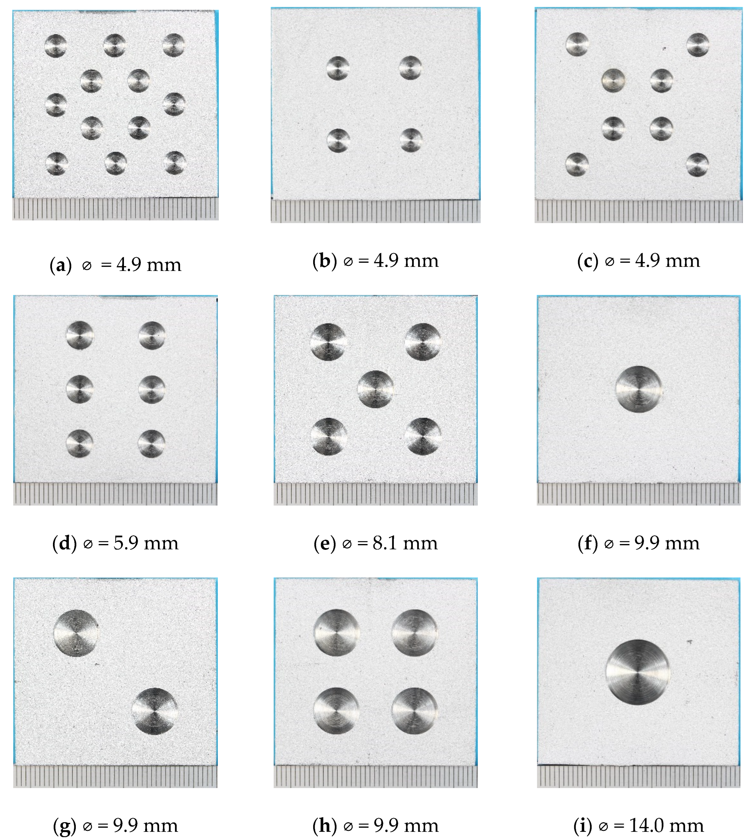
Figure 1. Photographs of specimens before testing showing holiday (damage) size and distribution. The number of holidays/total damage area % was: (a) 12/13.7%, (b) 4/4.6%, (c) 8/9.1%, (d) 6/9.9%, (e) 5/14.6%, (f) 1/4.6%, (g) 2/9.1%, (h) 4/18.3%, (i) 1/8.9%, (j) 1/14.8% and (k) 1/18.3%. Nominal diameter of each damage is also shown. The information is also provided in Table 3.
Applsci 13 01109 g001aApplsci 13 01109 g001b
Figure 2. Photographs of specimens after testing for 420 days in ASTM D1141 seawater. The number of holidays/total damage area % was: (a) 12/13.7%, (b) 4/4.6%, (c) 8/9.1%, (d) 6/9.9%, (e) 5/14.6%, (f) 1/4.6%, (g) 2/9.1%, (h) 4/18.3%, (i) 1/8.9%, (j) 1/14.8% and (k) 1/18.3%. The specimens are 43 mm × 40 mm.
Applsci 13 01109 g002
Figure 3. Measured open circuit potential (OCP) of TSA specimens showing the effect of damage size (a), and distribution (b). The measurements were carried out in synthetic seawater (ASTM D1141) at 25 °C.
Applsci 13 01109 g003
Figure 4. Calculated corrosion rate of TSA specimens showing the effect of damage size (a), and distribution (b). The measurements were carried out in synthetic seawater (ASTM D1141) at 25 °C.
Applsci 13 01109 g004
Figure 5. SEM micrographs of the cross-section of TSA specimen with one holiday (18.3% area) (a), (d); showing EDX patterns of regions 1 (b), 2 (c) and A1 (e) and A2 (f).
Applsci 13 01109 g005aApplsci 13 01109 g005b
Figure 6. EDX analysis of the deposit found on the surface of TSA.
Applsci 13 01109 g006
Figure 7. X-ray diffraction (XRD) pattern of (a) the deposit collected from the surface of the TSA, and (b) from the holiday/damage region. The pattern shown here was collected from the specimen with one holiday/damage (18.3% area).
Applsci 13 01109 g007
Table 1. Composition of substrate and wire consumable.
MaterialElement wt%
CSiMnPAlSVNFe
Carbon steel substrate0.120.391.390.014-0.0190.0650.003Bal.
Al (wire consumable)-0.07<0.01-Bal.--0.010.21
Table 2. Spray parameters used for the production of TWAS coatings.
Wire Diameter (mm)Air Pressure (bar)Stand-off Distance (mm)Incremental Step (mm)Traverse Speed (mm s−1)Current (A)Voltage (V)
2.351251030022030
Table 3. Summary of the specimens used for testing along with the area of damage.
Specimen IDNumber of HolidaysDiameter of Each Holiday (mm)Total Area of Damage (%)
A124.9 ± 0.113.7 ± 0.5
B44.9 ± 0.14.6 ± 0.2
C84.9 ± 0.19.1 ± 0.4
D65.9 ± 0.19.9 ± 0.3
E58.1 ± 0.114.6 ± 0.4
F19.9 ± 0.14.6 ± 0.1
G29.9 ± 0.19.1 ± 0.2
H49.9 ± 0.118.3 ± 0.4
I114.0 ± 0.18.9 ± 0.1
J118.1 ± 0.114.8 ± 0.2
K119.9 ± 0.118.3 ± 0.2
Disclaimer/Publisher’s Note: The statements, opinions and data contained in all publications are solely those of the individual author(s) and contributor(s) and not of MDPI and/or the editor(s). MDPI and/or the editor(s) disclaim responsibility for any injury to people or property resulting from any ideas, methods, instructions or products referred to in the content.