Abstract
A composite current sensor is designed with soft ferrite as the magnetizer in combination with giant magnetostrictive material (GMM) and fiber Bragg grating (FBG). The temperature drift characteristics of the GMM, detecting performances under thermal strain caused by temperature variation in the GMM rod, are investigated by simulating the coupled fields of magnetostriction and thermal expansion with the finite-element multi-physics method to explore the temperature-drift mechanism of the ferrite–GMM current detector. The sensing characteristics of the GMM-FBG current sensor under quasi-static current excitation at various work temperatures are evaluated by simulating thermal stress between the GMM and FBG to analyze the temperature drift mechanism of the Bragg wavelength signal modulated by FBG. Even though temperature elevation suppresses GMM magnetization and thereby reduces the slopes of stress–strain curves, the steering magnetization of magnetic domains in the GMM rod tends to saturation without appreciable thermal inhibition in the high-stress region of large current excitation, while the magnetostrictive strain is still abated by the reduction in magnetic flux density caused by the thermal expansion of GMM rods. The temperature elevation can also produce thermal stress between the GMM and FBG, which will decrease the detection sensitivity and testing range of the GMM-FBG current sensor. The temperature drift characteristics of the GMM-FBG are generalized into a formula by fitting the wavelength shifting as a function of thermal strain, which will significantly facilitate designing the scale calibration for various ambient temperatures. The present researchers provide a theoretical basis and experimental guidance for developing GMM-FBG current sensors with high sensitivity and stability.
1. Introduction
A digital and intelligent substation is the key part of the new generation power network for improving the voltage level of a high voltage power system, for which the photoelectric sensor is now expected (as a highly precise and safe detection technology) to be a prospective candidate for monitoring high voltage and large current. The photoelectric current sensors are mainly classified into optical glass current sensor, photoelectric hybrid current sensor and full fiber current sensor. The optical glass current sensor uses an optical glass bulk material with high Verdet constant as the detection probe, the sensitivity of which is apt to be affected by ambient temperature and mechanical vibration. For a full fiber current sensor, the optical fiber body is cooperatively exploited as the detecting element so that the sensitivity is also simultaneously influenced by ambient temperature, fiber birefringence and incident polarization. Inheriting from the traditional current sensor, the sensor head is completely composed of electronic circuits and a power supply in the photoelectric hybrid current sensor with an optical fiber as the signal transmission channel.
The fiber Bragg grating (FBG) sensor is a passive high-sensitivity device with high electrical insulation, strong resistance to electromagnetic interference, small size and mass, heat and corrosion resistance [1]. Especially, the wavelength modulation of an FBG is utilized for indirectly measuring physical quantities to realize complete electrical isolation in live detection [2]. Giant magnetostrictive material (GMM) represents the sensing and driving functions of conversion between electromagnetic and mechanical energies in high energetic density and coupling coefficients [3,4,5]. Therefore, the combination of FBG and GMM constituting sensors is a preferable scheme for the online detection of strong electromagnetic equipment with a broad prospective applications in power systems.
The GMM-FBG system for sensing electrical current has been extensively considered ever since it was proposed in the end of last century by a fiber-optic M-Z magnetic field sensor with a nickel coating as the magnetic conductive material to achieve successful current measurements [6,7,8]. The GMM-FBG demodulated with a linear edge filter shows a good linearity for detecting a 250–700 A alternative current of 60 Hz frequency [9]. The GMM-FBG sensing system has been applied to high-voltage transmission in simulation tests and achieved consistent results with theoretically predicted values [10]. It was found by means of a spectrum analyzer that the magnetostriction caused by a DC current can be exploited to regulate the central wavelength of an FBG [11,12,13]. A geometrically optimized structure of the GMM-FBG current sensor has acquired the maximum input current of 186 A and a global accuracy of 4.3% in the linear working region without any harmonic output signal [14].
Temperature drift poses a significant challenge in optical fiber current sensors, where precise measurements are vital for applications in high-voltage power systems and plasma current monitoring. The integration of giant magnetostrictive material (GMM) with fiber Bragg grating (FBG) sensing principles offers promise for high-current detection but requires a thorough understanding of temperature drift characteristics to ensure accuracy and reliability. Recent researchers have explored innovative solutions, including a temperature-compensated method using FBG-GMM sensors and simultaneous temperature and Faraday rotation extraction in polarimetric fiber-optic sensors [15,16]. Additionally, performance assessments of fiber-optic current sensors have underscored the importance of addressing mechanical perturbations and optimizing sensor reliability [17]. In particular, Zhang et al. presented a mathematical model of temperature compensation for a GMM-FBG current sensing system, leading to a significant improvement in the accuracy of measuring 60 A current at 40 °C [18]. These studies delve into a comprehensive analysis of temperature drift mechanisms in GMM-FBG current sensors, leveraging finite-element multi-physics simulations to elucidate the interplay of solid mechanics, magnetostatics, and thermal expansion.
In the present study, a new practical structure for the GMM-FBG current sensor is presented and investigated in terms of its temperature drift mechanism. The effects of elevating temperature on GMM-FBG sensing performances are elucidated through finite element multi-physics simulations of mechanical–electromagnetic–thermal correlations. According to the temperature drift characteristics, a general formula for calibrating GMM-FBG current measurements at various temperatures is eventually obtained by fitting the temperature drift curves of thermal strains.
2. FBG Sensing Principle
The peak wavelength of optical reflection (Bragg wavelength) in FBG depends on the grating period of refractive index and core refractive index, which will be directly determined by temperature and strain. Accordingly, temperature and strain are two basic factors that will cause the change in the FBG Bragg-wavelength response and should be considered for FBG sensing measurements of other physical quantities. The strain-caused variation in the Bragg wavelength of FBG sensor for current detection originates from the elasto-optical effect of fiber stretching (grating period change) and core refractive index. When the fiber is subjected to axial (set as z coordinate) stress, the produced lateral stretching or compressing strain results in the variation of the FBG grating period, while the change in the effective refractive index in the fiber core neff can be deduced from the elasto-optical tensor and the strain tensor as follows:
where the subscripts I = 1, 2, 3 and 4, 5, 6 indicate, respectively, the real and imaginary (the electric field attenuation of incident light) parts of the complex refractive index along three directions in the fiber core. There is no shear stress when the fiber is stretched, and the strain-caused change in the refractive index along the fiber axial direction for isotropic material can be predigested as:
where P11 and P12 denote three no-zero elasto-optical coefficients, ν symbolizes Poisson’s ratio of the fiber core, and εz represents the strain along the fiber axis. Accordingly, the effective elasto-optical coefficient Peff can be defined by the following equation:
The strain-caused variation in Bragg wavelength of FBG reflection is finally presented by defining the strain sensitivity in the first and second order Ke′ and Ke″, respectively, as follows:
where λB and ΔλB indicate the Bragg wavelength and its variation, respectively. For the germanium-doped quartz of the core material in a representative optical fiber, Peff = 0.22 and the first-order strain sensitivity Ke′ = 0.78, while the second-order sensitivity Ke″ is so small that it can be ignored in practical applications, by which the Bragg wavelength can be considered as being changed linearly with fiber axial strain. To this end, an FBG Bragg reflection wavelength is determined by an effective refractive index and grating period of a single-mode fiber, as described by Equations (1)–(4). As the FBG is subjected to stress induced by the target, detecting physical quantities along the fiber axial direction at a certain ambient temperature, the effective refractive index and grating period will accordingly change to shift the Bragg wavelength and realize the strain–wavelength modulations.
3. Designed Structure of GMM-FBG Current Sensor
According to GMM magnetostrictive and ferrite magnetization characteristics, the designed GMM-FBG current sensor consists of a ferrite magnetizer and GMM magnetic-strain sensor (rod) on which the FBG strain-wavelength optical modulator is firmly attached in the rod axial direction, while the rare earth giant magnetostrictive material (Tb-Dy-Fe alloy) and soft magnetic ferrite are adopted for the GMM rod and substantial magnetizer, respectively, as shown by the 3D model given in Figure 1. A notched ferrite ring (diameter = 300 mm) with a circular section (diameter = 30 mm) is used as the magnetic conduction loop (magnetizer), in which the two notch ends can be regarded as two magnetic poles and a sunken cylindrical hole with a depth being identical to diameter (4 mm) is designed on the surface of one pole to be inserted and fixed on the bottom by the longitudinal cylindrical GMM rod with a diameter of 4 mm and an effective length (of ferrite) of 15 mm. This sag hole is designed to fix the GMM rod and avoid its axis deviating from the magnetic field direction, which can increase the contact area between ferrite and GMM and thus increase the magnetic flux injected from the ferrite magnetizer into the GMM rod. An air gap of 0.1 mm width is left between the end of the GMM rod and the other opening pole of the magnetic-conducting ferrite as a free space for GMM magnetostrictively stretching. In order to effectively introduce magnetic flux from the ferrite magnetizer into the GMM rod, the counterpart surfaces of the GMM tip and ferrite magnetic pole, respectively, at the two sides of the air gap are designed into convex and concave concentric hemispheres with a radius difference just being identical to the gap width. These design schemes can fix the GMM rod, avoiding its axis deviating from the magnetic field direction and enlarging the contact area between ferrite and GMM, which favors the magnetic flux injection from the ferrite magnetizer into the GMM rod and thus increases the sensing efficiency under electrical current excitation.
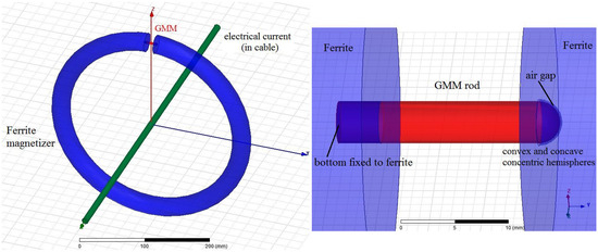
Figure 1.
The overview (left panel) and the local scaled (right panel) schematics of the GMM-ferrite assembly component in the GMM-FBG current sensor model.
4. Multi-Physics Simulation Analyses of GMM-FBG Current Sensor
The temperature drift of the Bragg-wavelength signal modulated by the GMM-FBG current sensor in the process of detecting the current can be attributed to three dominant mechanisms: (1) thermal strain directly bringing about the geometry changes of the ferrite magnetizer, GMM and air gap, which leads to distribution changes in the current-induced magnetic field in the GMM rod; (2) the variation of ambient temperature (device operating temperature) causes thermal strains in the GMM rod, accordingly altering the grating period and Bragg wavelength of FBG fixed to the GMM side surface; (3) the GMM magnetostrictive characteristics and FBG core refractive index are shifted by varying temperatures, while the infinitesimal change in ferrite permeability caused by temperature change can be ignored. Due to the actual condition that the thermal strain caused by the change in operation temperature in ambient range has little effect on the geometric structure of the GMM-FBG current sensor, the first temperature drift mechanism mentioned above can be ignored. Therefore, the finite element multi-physics simulations are carried out for investigating the latter two temperature drift mechanisms in the present study.
4.1. Multi-Physics Simulation Methodology
The magnetostrictive performances of the GMM rod under the multiple physical loads of magnetic field, thermal field and stress field can be simulated by establishing the constitutive model of nonlinear coupling solid mechanics, magnetic field and heat transfer based on thermodynamic theory. A nonlinear-coupling constitutive model that can comprehensively describe GMM physical responses synergistically under mechanical, magnetic and thermal loads is utilized for predicting the magnetostrictive and magnetization curves under strain field at different temperatures [19]. A GMM rod is generally applied by external magnetic field or stress along the axial direction in practical applications, which means the magnetostrictive strain and magnetization generated under a mechanical–magnetic–thermal multi-field are along the axial direction of the GMM rod. Therefore, it is supposed that GMM is a nonlinear isotropic material with the stress/strain, magnetic field and magnetization being correlated to each other by the magnitude of mechanical tensor components and the magnetic vector, and the GMM anisotropic compensation temperature Tr (easy axis conversion temperature) should be used to construct the multi-physics coupling constitutive model [20,21].
The GMM rod of the GMM-FBG current sensor designed in this paper is freely stretching due to the air gap at the top of the hemispherical surface. The magnetic field introduced by ferrite into GMM is mainly along the cylindrical axis of the GMM rod. Therefore, no pre-stress arises in the GMM rod during current detection, and the stress/strain originates from magnetostriction and thermal expansion, in which the temperature effect on the thermal expansion and magnetostriction should be adequately considered. Complying with the definitions of magnetostriction modulus Em = ∂σ/∂λ, relative permeability μr = (1 + ∂M/∂H) and piezomagnetic coefficient dm = ∂λ(σ,H)/∂H (λ, σ, M and H denote the magnetostrictive coefficient, strain, magnetization intensity and magnetic field strength, respectively), the constitutive model used for the GMM rod in multi-physics finite element simulations is simplified to the thermo-magnetostriction constitutive relations as follows:
where the characteristic parameters of material attributes are defined and symbolized with specific values as listed in Table 1. The magnetostrictive response curves of ferrite–GMM assembly for current detection at different temperatures are simulated in a multi-field coupling model of solid mechanics/magneto-statics/thermal expansion with the expressions (5)–(8) for magnetostrictive material characteristics being input into the material attributes of ferrite–GMM as implemented by COMSOL Multiphysics software(COMSOL Inc., Stockholm, Sweden)

Table 1.
Material characteristics of GMM rod and ferrite magnetizer adopted for multi-physics simulations of solid mechanics/magnetostatics/thermal expansion.
Although the temperature drift in the magnetic characteristics of the ferrite material will have no palpable interference on the magnetic flux of the GMM rod, the thermal strain in the ferrite magnetizer should cause a significant change in the air gap at the free terminal of the GMM rod, directly affecting the magnetic flux density in the GMM rod. Therefore, the magnetic characteristics of the ferrite material are considered to be constant for different temperatures only when the thermal expansion model of solid mechanics is resolved for a ferrite magnetizer in multi-physics simulations. The magnetic properties and thermal expansion coefficients of the ferrite material adopted in simulations are listed in the bottom line of Table 1.
As implemented by the multi-physics field–coupling correlation of the COMSOL 4.4 finite-element software package, the thermal strain fields in ferrite–GMM-FBG current sensor are specifically evaluated, which are self-consistently coupling with magnetostatic fields. The free triangular mesh generations with the Delaunay triangulation algorithm are adopted to refine local mesh at the position where the magnetic or strain fields vary greatly. The minimum mesh elements are adjusted with the adaptive method until the obtuse-angle triangulation disappears, and the maximum elements in regions of the ferrite magnetizer/current cable/air computational domain, GMM rod/air gap and FBG are, respectively limited, to 0.1, 0.05 and 0.001 m. The mesh refinement amplitude (growth rate of element amount) and the relaxation degree of the narrow region are set to 30% and 1, respectively, for mesh generations. The high-density mesh operations allow the finite-element solutions to be obtained with a sufficient accuracy. The relative tolerance of the iterative solution and the nonlinear residual are controlled below 10−4 and 0.001, respectively.
4.2. Ferrite–GMM Magnetostrictive Field Analyses
The magnetic field vectors of the ferrite–GMM assemblage and the magnetic induction intensity distribution on the longitudinal and lateral cross-sections of the GMM rod without current excitation and thermal strain (i = 0, T = 273 K) are shown in Figure 2. It is indicated that the residual magnetic moments of the ferrite magnetic material in a proper integrated structure with the GMM material can provide a sufficient magnetic field and effectively aggregate the magnetic flux to introduce a uniform magnetic field of 17 kA/m as an appropriate initial working point for the GMM-FBG current sensor into the GMM rod except for a small local area at the air gap and ferrite junction. In contrast to the dominant part of the GMM rod and the ferrite magnetizer, the magnetic induction intensity changes obviously in the region caved into ferrite at the rod bottom with a high-density magnetic flux being introduced from the cylinder side of the GMM rod through the locations near the surface of the ferrite magnetic pole, as shown in Figure 2a. The high magnetic induction intensity originates from the abrupt change in geometry at the circular intersection between the side of the GMM cylinder and the surface of the ferrite pole, which accounts for the major introduction of magnetic flux into the GMM rod. Despite the high magnetic induction intensity around this circular intersection in the connection of the GMM rod and ferrite magnetizer, the magnetic field vectors are axisymmetrically distributed with the cylinder axis of the GMM rod, as shown in top panel of Figure 2a, will not cause the lateral swing of the GMM rod by the non-axisymmetric strains during current detection, and the strains generated by magnetostriction are negligible relative to the air-gap width, leading to a uniformly distributed magnetic field along the GMM rod axis. It is especially noted that the hemispherical surface at the tip of the GMM rod in contact with the air gap facilitates the magnetic flux aggregation in the GMM rod and avoids flux leakage at the air gap.
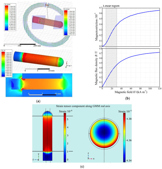
Figure 2.
(a) Magnetic field vector (top panel) in ferrite-GMM assemblage and magnetic induction intensity (bottom panel, contoured on GMM surface and axial longitudinal section) in GMM rod; (b) Magnetostriction (top panel) and magnetic flux density (bottom panel) versus magnetic field on the center of the GMM rod; (c) Longitudinal stretching component of strain tensor field in the GMM rod contoured on the longitude (left) and cross (right) sections.
The changes in magnetic flux and magnetostriction of the GMM rod in the quasi-static process of slowly raising the direct current magnitude are simulated through continuously changing the excitation current magnitude in the ferrite–GMM center by setting the direct current magnitude as a variable with the parameter-scanning function of COMSOL Multiphysics software. Accordingly, the stable linear working region and the measurement range of detecting the current by the GMM-FBG current sensor are obtained as the simulated results of magnetostriction (λ-H) and magnetization (B-H) along the longitudinal axis of the GMM rod at the GMM center, as shown in Figure 3b. When the current (in positive or negative direction) magnitude exceeds ~600 A, the variation curve of the GMM magnetostrictive coefficient with a magnetic field converts from the linear region of 8–35 kA/m to a high-order function trending to saturation, implying that the nonlinear distortions will arise in current detection so as to limit the detecting range of the ferrite–GMM assemblage into 0~±600 A, which still are qualified for current measurements in a high-voltage power system.
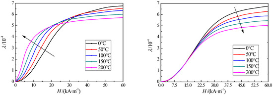
Figure 3.
Magnetostrictive coefficient varying with the magnetic field magnitude at the center of the GMM rod at 0–200 °C temperatures for the simulations with and without consideration of thermal strain in ferrite loop, being shown in the left panel and right panel, respectively.
As illustrated in Figure 2c, for the longitudinal stretching component of the strain tensor field contoured over the center cross-section and the longitudinal section of the GMM rod, the strain along the longitudinal axis (yy component of the strain tensor) is uniformly distributed only with 1% change along the radial direction in the effective part (out of the ferrite magnetizer) of the GMM rod, except for the narrow areas near the bottom surface and the top terminal at the air gap where the magnetostriction is precipitately reduced due to the end-edge effect. The part of the GMM rod exposed in air with an effective length of 15 mm presents at least a constant magnetostriction region of 13 mm, which is sufficient for a uniform strain modulation workspace of FBG in 10 mm length and two exports, leading out fiber tails.
4.3. Temperature Drift Characteristics and Mechanism of Ferrite–GMM
By means of setting the magnitude of the DC current at the magnetizer center as a scanning variable, the quasi-static variation of the strain–magnetic coupled fields in the ferrite–GMM assemblage with an excitation current at different temperatures is simulated to analyze the characteristics and mechanism of temperature-drift magnetostrictions. For the purpose of analyzing the temperature drift of the GMM magnetostrictive response deriving from the thermal strain in the ferrite magnetizer, in addition to modeling the GMM rod with a full coupling of solid mechanics, magnetic field and temperature, the magnetic field in the ferrite magnetizer is simulated comparatively with and without the coupling correlation of thermal expansion, as the results show in Figure 3. Under the thermal–magnetic coupled fields of the GMM rod, the temperature elevation affecting the ferrite magnetization can be seen as the decrements in the saturation magnetization and saturation magnetostrictive coefficient, which conforms to the basic law of restraining a magnetic domain turning to magnetization in a ferromagnet by exacerbating atomic vibrations when the temperature increases, as shown in the right panel of Figure 3, illustrating that the current detection performances of the ferrite–GMM assemblage working in a linearly magnetostrictive region will not shift with temperature variation. Since the GMM magnetization under thermal–magnetic coupled fields is characterized by the nonlinearity and saturation of changing permeability with the increasing magnetization, the introduction of magnetic flux into a GMM rod will also affect its magnetostrictive performance. As a result of thermal expansion in the ferrite magnetizer, the air gap at the tip of the GMM rod decreases in width, and thus, the magnetic flux density of the GMM rod increases, which means a higher magnetic conductivity of ferrite magnetizer, accounting for the shrinkage and low-field drift of the linear working region and the increase in magnetostrictive efficiency (curve slope of magnetostriction characteristics). Therefore, temperature elevation will cause the shift of static working point and the sensitivity increment of the current–strain response, leading to a nonlinear drift of detection signal from the highly sensitive FBG wavelength modulator. In addition, the measuring range of the GMM-FBG current sensor decreases with the increase in temperature, and the scale gauge of the current measurement needs to be readjusted. It is thereby suggested that the temperature drift of the ferrite–GMM-FBG current sensor in the process of current detection mainly comes from the thermal strain of the ferrite magnetizer. Moreover, the change in the FBG center refractive index as a function of temperature (photoelasticity) can also cause temperature drift in the modulation signal of the Bragg wavelength, which will be further discussed and analyzed in the next section.
The magnetostrictive stress–strain curves of the GMM rod at the center position during the change in quasi-static DC current at different temperatures are shown in Figure 4, which indicates the thermal–mechanical coupling attributes of the GMM rod in the ferrite–GMM assemblage. The shift of the GMM stress–stain curve with temperature elevation, which has been modeled by the temperature variation coefficient β of a GMM material property as listed in Table 1, represents the fact that the steering magnetization of magnetic domains inside the GMM rod will be substantially inhibited by increasing the temperature, resulting in a degradation of magnetostrictive performance. In addition, the thermal expansion will alter the magnetic flux distribution in the GMM rod and thus accommodate the magnetization state and magnetostrictive performance, which nevertheless could be manifested only under a high magnetic field excited by a large current.
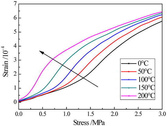
Figure 4.
Magnetostrictive stress-strain curves at the center of the GMM rod at 0~200 °C temperatures.
The deviation of the stress-strain curve with temperature variation indicates that the slope of the stress-strain curve decreases with temperature elevation due to the inhibition on magnetization in the GMM rod, while the temperature inhibition disappears due to the magnetization saturation of the magnetic domain steering in the GMM material, and the thermal-expansion-caused suppression on magnetic flux introduction arises to evidently reduce the magnetostriction of the GMM rod at the high-stress region under large current excitation.
4.4. Temperature Drift Characteristics of GMM-FBG Bragg Wavelength
In the modeled GMM-FBG optical modulator, the FBG is directly contacted with the GMM rod on the side surfaces to construct a GMM-FBG strain-optical modulation component capable of effectively transferring magnetostrictive strain along the axial direction in the GMM rod under current excitation, as shown in Figure 5. The rectangular groove in a dimension of 0.2 mm × 0.2 mm × 13 mm is excavated out on the side surface and along the longitudinal axis of the GMM rod, in which a bare FBG (without an outer protective layer) with a tail fiber is placed and fixed by a filling binder in the interval space. The FBG in a sufficient length of 10 mm is located at the center of the long and narrow groove with two residual spaces of 1.5 mm length at the FBG terminals to accommodate the tail fibers, as shown in Figure 5. Epoxy resin material is used as a binder for fixing and protecting the bare FBG. The FBG is specified by the standard 9/125 μm single-mode fiber: the core diameter and cladding thickness are 9 μm and 125 μm, respectively; the core material is defined by germanium-doped quartz as an elasto-optical coefficient of P11 = 0.121 and P12 = 0.27, Poisson’s ratio of ν = 017, and refractive index of n = 1.469 (1550 nm). For specifying boundary conditions in finite-element simulations, the solid mechanical model of GMM-FBG fixation is constructed by setting the joint constraint (relative fixed constraint) to the contacting interfaces of the FBG cladding layer/solid binder, GMM/binder (five faces of groove), and FBG core/cladding.
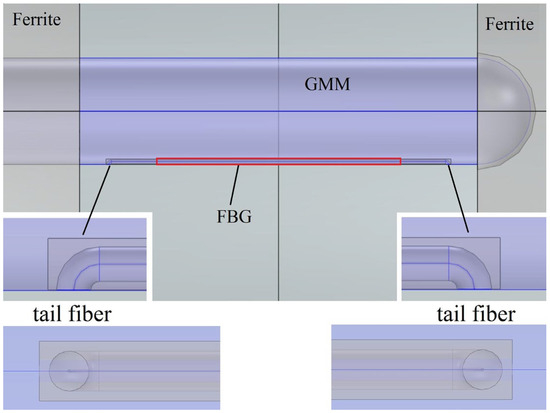
Figure 5.
GMM-FBG coupled configuration of ferrite–GMM-FBG current sensor model.
Due to the difference in the thermal expansion coefficients of FBG and GMM, the refractive index of the FBG core will be changed with the elasto-optical effect when thermal stress arises at the interface between FBG and GMM from temperature variation, while the Bragg wavelength temperature drift deriving from magnetostriction and thermal expansion in the ferrite–GMM assemblage is attributed to the temperature dependence of the current–magnetic–strain sensing response and static working point, which can be directly evaluated by equation (a) according to the simulation results in Section 4.3. Therefore, due to a particular interest of investigating the temperature drift caused by thermal stress in the FBG-GMM optical modulator, the multi-physics simulations of magnetostriction and thermal stress coupled fields in a ferrite–GMM-FBG current sensor are performed without modeling the thermal expansion in a ferrite magnetizer.
According to the elasto-optical effect, the refractive index of the FBG core being altered by thermal stress in the GMM-FBG optical modulator can be calculated from the elasto-optical tensor of the FBG core material with Equation (2) and the results of the thermal stress/strain simulations with material characteristics specified for the GMM-FBG modulator as listed in Table 2. The small thermal expansion coefficients of silica quartz glasses making up FBG imply that no considerable expansion or shrinkage will appear when the temperature changes. In contrast, the thermal expansion coefficient of epoxy resin used for gluing FBG on the GMM side in the groove is significantly higher than that of FBG. As a result, the thermal stress/strain along the longitudinal axis will be produced under the restraint of the GMM rod when the temperature changes. The sensing characteristics of the GMM-FBG current sensor represented by the Bragg wavelength as a function of the excitation current at various temperatures are shown in Figure 6. The Bragg wavelength differential signal sensitive to static current represents a substantial abatement by temperature elevation in both the gradient and amplitude of response curves, leading to the foreseeable reductions of sensitivity and range, which means the GMM-FBG current sensor needs to be calibrated according to the work temperature.
Table 2.
Material characteristics specified for simulating thermal strains in a GMM-FBG optical modulator.
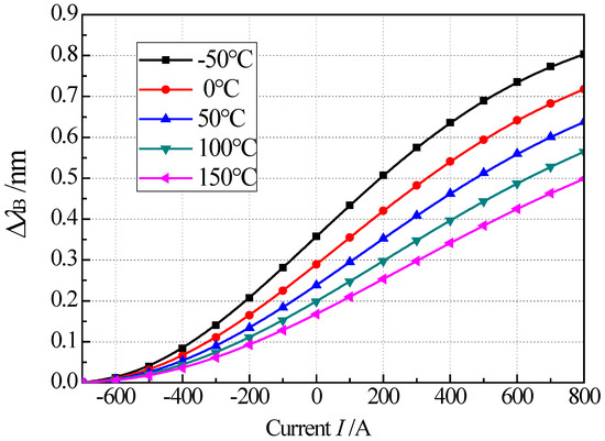
Figure 6.
Temperature-drifted sensing characteristics of the GMM-FBG current sensor, which are represented by the Bragg wavelength differential as a function of excitation current at −50–150 °C temperatures.
The temperature-drifted curves of the current-Bragg wavelength-sensing characteristics obtained by multi-physics finite-element simulations are numerically fitted with Tr = 273 K as the reference temperature to reach a temperature-drift function representing the sensing performances of the GMM-FBG current sensor as follows:
where Kf denotes the FBG optical modulation sensitivity, λB represents the Bragg wavelength under zero excitation, εs symbolizes the saturated magnetostrictive strain of the GMM material, I and T are the detected electrical current in unit A and working temperature in unit K, respectively, and the fitting constants are resolved to a = 7.6 × 10⁻⁴, b = 0.025, c = 17.8, and g = 758. According to the fitted Formula (9), the measuring scale and range of the GMM-FBG current sensor can be calibrated for different working temperatures.
5. Conclusions
By combining GMM magnetostriction and the FBG grating sensing approach, a GMM-FBG current sensor is designed with a soft ferrite as the magnetic conduction material for detecting a large electric current in a high-voltage power system. Conforming to the complete nonlinear constitutive model for the GMM material, the temperature drift characteristics and mechanism of ferrite–GMM current detection assembly are analyzed through finite-element multi-physics simulations of correlating solid mechanics, magnetostatics and thermal expansion. The Bragg wavelength response of the GMM-FBG optical modulator at various temperatures is evaluated by elasto-optics and multi-physics simulations of coupling magnetostriction and thermal strain to elucidate the temperature drift characteristics and mechanism. In addition to the full-coupling model of the GMM rods, the physical field of thermal expansion is also comparatively correlated to the magnetostatic field in the ferrite magnetizer to analyze the thermal strain effect on the magnetic-strain response of the ferrite–GMM assemblage.
It is indicated by the temperature-drifted magnetostrictive stress–strain relations that the slope of the stress–strain curve decreases to inhibit GMM magnetization as the temperature increases, while the GMM rod tends to saturate in magnetization as the temperature inhibition fades away in the high-stress region of large current excitation. In addition, the magnetic flux abatement caused by thermal expansion in the GMM rod accounts for the dominant degradation of magnetostrictive performance. The significant difference in the expansion coefficients of FBG and GMM being cemented to each other on the side surface leads to thermal stress as temperature varying in the GMM-FBG modulator, which reduces the sensitivity and range of this current sensor. Finally, the sensing characteristics of the GMM-FBG current sensor at various temperatures achieved by multi-physics finite-element simulations are numerically fitted to a temperature-drift function, which provides a valuable insight into the scale calibration required for highly accurate current measurements in the elevated temperature environment.
Author Contributions
Conceptualization, investigation, W.-F.S.; methodology, formal analysis, data curation, Y.L.; resources, project administration, funding acquisition, W.Z.; writing—original draft preparation, writing—review and editing, W.-F.S. All authors have read and agreed to the published version of the manuscript.
Funding
This research was funded by the Science and Technology Project of Shenzhen Power Supply Bureau Co., Ltd. (Grant No. 09000020220301030900517) and the National Research Foundation, SP Group, Energy Market Authority of Singapore and Nanyang Technological University under Energy Programme (Grant No. EMA-EP010-SNJL-002). Grand No. KFKT202210 from Key Laboratory of Special Machine and High Voltage Apparatus (Shenyang University of Technology), Ministry of Education.
Institutional Review Board Statement
Not applicable.
Informed Consent Statement
Not applicable.
Data Availability Statement
No additional data are available.
Conflicts of Interest
The authors declare no conflict of interest. The funders had no role in the design of the study; in the collection, analyses, or interpretation of data; in the writing of the manuscript; or in the decision to publish the results.
References
- Sun, F.F.; Zhao, H.; Zhang, K.Y. A novel fiber Bragg grating ac current transformer with temperature-compensation. J. Optoelectron. Laser 2015, 12, 0618. [Google Scholar]
- Tian, F.F.; Cong, J.W.; Yun, B.F.; Cui, Y.P. A fiber Bragg grating current sensor with temperature compensation. Optoelectron. Lett. 2023, 5, 34–351. [Google Scholar] [CrossRef]
- Katabira, K.; Yoshida, Y.; Masuda, A.; Watanabe, A.; Narita, F. Fabrication of Fe–Co magnetostrictive fiber reinforced plastic composites and their sensor performance evaluation. Materials 2018, 11, 406. [Google Scholar] [CrossRef] [PubMed]
- Luo, M.; Li, W.; Wang, J.; Wang, N.; Chen, X.; Song, G. Development of a novel guided wave generation system using a giant magnetostrictive actuator for nondestructive evaluation. Sensors 2018, 18, 779. [Google Scholar] [CrossRef] [PubMed]
- Tong, J.; Jia, Y.N.; Wang, W.; Yang, W.; Wang, S.Y.; Liu, X.L.; Lei, Y.Q. Development of a magnetostrictive FeNi coated surface acoustic wave current sensor. Appl. Sci. 2017, 7, 755. [Google Scholar] [CrossRef]
- Qiu, Z.C.; Sun, R.; Teng, Y.T.; Chen, N.; Hong, L. Design and test of a low frequency Fiber Bragg Grating acceleration sensor with double tilted cantilevers. Opt. Commun. 2022, 507, 127663. [Google Scholar] [CrossRef]
- Díaz-Rubio, A.; García-Miquel, H.; García-Chocano, V.M. In-plane omnidirectional magnetic field sensor based on Giant Magneto Impedance (GMI). J. Magn. Magn. Mater. 2017, 444, 249–255. [Google Scholar] [CrossRef]
- Shi, Y.; Ma, Y.Q.; Wang, Y.K. Magneto-elastic-optical coupling of Terfenol-D based optical fiber magnetic field sensors. Mater. Res. Express 2019, 6, 86106. [Google Scholar] [CrossRef]
- Han, J.H.; Hu, H.F.; Wang, H.; Zhang, B.; Song, X.W.; Ding, Z.Y.; Zhang, X.Z.; Liu, T. Temperature-Compensated Magnetostrictive Current Sensor Based on the Configuration of Dual Fiber Bragg Gratings. J. Light. Technol. 2017, 22, 4910–4915. [Google Scholar] [CrossRef]
- Wang, C.; Huang, Z.; Li, G.; Zhang, S.; Zhao, J.; Zhao, N.; Cai, H.; Zhang, Y. Simultaneous Temperature and Strain Measurements Using Polarization-Maintaining Few-Mode Bragg Gratings. Sensors 2019, 19, 5221. [Google Scholar] [CrossRef]
- Wang, T.S.; Guo, Y.B.; Bai, B.; Hu, G.J.; Li, X.B. Optical add/drop multiplexer with giant magnetostrictive tunable fiber bragg gratings. Acta Photonica Sin. 2003, 32, 1106–1109. [Google Scholar]
- Luo, Y.; Lei, X.; Shi, F.; Peng, B. A novel optical fiber magnetic field sensor based on Mach-Zehnder interferometer integrated with magnetic fluid. Optik 2018, 174, 252–258. [Google Scholar] [CrossRef]
- Kumagai, T.; Ohnuki, W.; Hayashiya, H.; Nishida, K. Interferometric Fiber-Optic Electric Current Sensor for Railway Power Systems. IEEJ Trans. Sens. Micromach. 2013, 133, 42–47. [Google Scholar] [CrossRef]
- Xiong, Y.L.; Zhao, H.; Zhang, J.; Zhao, H.J.; Wang, S.R. Research on optical current sensor based on the fiber Bragg grating. Acta Opt. Sin. 2010, 30, 949–953. [Google Scholar] [CrossRef]
- Robalinho, P.; Melo, M.; Frazao, O.; Ribeiro, A.B.L. Temperature-Monitored Fibre Optic Current Sensor Using Channelled-Spectrum Analysis. IEEE Photonics Technol. Lett. 2022, 34, 1308. [Google Scholar] [CrossRef]
- Zhao, H.; Sun, F.F.; Yang, Y.Q.; Cao, G.Y.; Sun, K. A novel temperature-compensated method for FBG-GMM current sensor. Opt. Commun. 2013, 308, 64–69. [Google Scholar] [CrossRef]
- Gusarov, A.; Leysen, W.; Beaumont, P.; Wuilpart, M.; Batistoni, P. Performance assessment of plasma current measurement at JET using fibre optics current sensor. Fusion Eng. Des. 2021, 165, 112228. [Google Scholar] [CrossRef]
- Zhang, W.C.; Lai, Y.B.; Zhao, H.; Zhang, L.Y.; Shi, Y.B. Structural optimization and temperature characteristic analysis of GMM-FBG fiber current sensor. Electr. Mach. Control 2019, 23, 104–111. [Google Scholar]
- Zheng, X.J.; Sun, L. A nonlinear constitutive model of magneto-thermo-mechanical coupling for giant magnetostrictive materials. J. Appl. Phys. 2006, 100, 063906. [Google Scholar] [CrossRef]
- Kendall, D.; Piercy, A.R. Magnetisation processes and temperature dependence of the magnetomechanical properties of Tb0.27Dy0.73Fe1.9. IEEE Trans. Magn. 1990, 26, 1837–1839. [Google Scholar] [CrossRef]
- Mori, K.; Cullen, J.; Clark, A. Magnetostriction in Tb0.27Dy0.73Fe2: Evidence for a low-temperature transition. IEEE Trans. Magn. 1983, 19, 1967–1968. [Google Scholar] [CrossRef]
- Fang, S.X.; Zeng, L.P.; Chu, Y.C. The development and experiment of rare-earth giant magnetostrictive ultrasonic transducer. Electromach. Mould 2019, 6, 61–65. [Google Scholar]
Disclaimer/Publisher’s Note: The statements, opinions and data contained in all publications are solely those of the individual author(s) and contributor(s) and not of MDPI and/or the editor(s). MDPI and/or the editor(s) disclaim responsibility for any injury to people or property resulting from any ideas, methods, instructions or products referred to in the content. |
© 2023 by the authors. Licensee MDPI, Basel, Switzerland. This article is an open access article distributed under the terms and conditions of the Creative Commons Attribution (CC BY) license (https://creativecommons.org/licenses/by/4.0/).