Article

Analysis of Grating Lobe Effects on GEO DSC Distributed Antennas

Institute of Systems Engineering, Academy of Military Sciences, Beijing 100141, China
*
Author to whom correspondence should be addressed.
These authors contributed equally to this work.
Appl. Sci. 2023, 13(19), 10912; https://doi.org/10.3390/app131910912
Submission received: 28 June 2023 / Revised: 21 September 2023 / Accepted: 22 September 2023 / Published: 1 October 2023
(This article belongs to the Special Issue Antenna: Design Methodology, Optimization, and Technologies)

Abstract

:
Traditional single-antenna systems have inherent limitations in terms of antenna gain, anti-interference capability, and flexibility. To overcome these challenges, satellite-mounted distributed antenna systems disperse multiple antennas at different positions on the satellite to improve the reception quality and signal-to-noise ratio of satellite signals, enhancing the performance of the satellite communication system without additional bandwidth or transmission power. However, the dispersed locations and long distances between antennas on the satellite result in less compact spacing compared to terrestrial distributed antennas, leading to the generation of a significant number of grating lobes. The distributed satellite cluster (DSC) approach revolutionizes the traditional mode of satellite utilization, enabling close collaboration among distributed loads. In this study, we analyzed the impact of grating lobes produced by DSC distributed antennas in geostationary Earth orbit (GEO) and simulated the grating lobe patterns of two 1 m circular aperture satellite antenna arrays in GEO. The simulation results revealed that the relative position change of the satellites affected the width and number of interference fringes in a certain ground area, while change in the carrier phase led to the translation of the interference fringes. To mitigate the grating lobes, we employed a sparse array technique. The simulation results demonstrated that the sparse array effectively suppressed the grating lobes but at the expense of a decrease in the sidelobe level and beamwidth.

1. Introduction

The antenna is the core device of satellite communication payloads, and traditional single antenna transceiver systems face limitations with restricted frequency band resources. Higher antenna performance can only be achieved by increasing the physical aperture, amplifier power limit, or efficiency [1,2]. In this context, distributed antennas provide higher gain, narrower beamwidths, and lower transmittance costs. In recent years, the rapid development of satellite communication systems has led to increasing demands for the frequency, polarization, and reconfigurability of antenna direction maps [3,4]. Distributed antennas have emerged as an important way to enhance the performance of satellite antennas by allowing the addition or removal of nodes according to communication needs to achieve antenna reconfigurability [5]. By utilizing spatial dimension resources, distributed antennas can increase transmission reliability and rates without adding bandwidth or transmission power, meeting the demand for high-speed, efficient, and stable satellite communications. Distributed antennas can be dispersed flexibly on different satellite locations to improve signal coverage and communication quality, obtain higher resolution and anti-interference capability, and have good application prospects in satellite communication, navigation, and antenna arrays [6,7]. Projects such as SpaceX’s Starlink, T-Mobile’s 5G Multiple Input Multiple Output (MIMO) satellite network, and Intelsat’s Enhanced Performance and Interactive Capabilities Next Generation (EpicNG) satellite network have all involved considering equipping with distributed antennas. However, when considering the long distances between satellites, the use of distributed antennas can result in the generation of a significant number of grating lobes after beamforming, leading to a decrease in gain and dispersion of radiated energy. Additionally, due to the involvement of multiple antennas in distributed antenna systems, there are significant difficulties in data processing and combination. Therefore, distributed antenna systems still face technical and practical challenges. To address the issue of long distances between satellites, the concept of DSC has emerged as a promising solution [8,9]. The typical architecture of the DSC encompasses the F6 (Future, Fast, Flexible, Fractionated, Free-Flying) Program, a space-based group, and GRACE [10]. DSC has revolutionized the traditional approach to using satellites. Instead of relying on large, heavy satellites, DSC uses multiple small, lightweight satellites that are placed in close proximity to each other and independently distributed in GEO or LEO orbits. DSC uses multi-star co-orbital control, high-speed networking, and cooperative processing technologies to integrate various resources to perform specific tasks together and achieve high-capacity, high-speed data network transmission and exchange in space [11]. DSC addresses two major issues in satellite communication. Firstly, DSC can overcome the limited capacity of single satellite platforms and low antenna gain by utilizing multiple small satellites that work together to increase network capacity and improve antenna gain. Secondly, the distance between DSC satellites is much smaller than traditional satellite communication satellites, which can reduce synchronization errors and interference. This helps to mitigate the difficulty of antenna synchronization and signal quality degradation caused by the distance between satellites. As a result, DSC brings a new perspective to the design and application of satellite-based distributed antennas.
DSC antennas utilize multi-star coordination to achieve multi-signal collaboration and distributed beamforming, providing high accuracy, performance, and reliability [12]. However, the realization of star-borne distributed antennas will face some difficult problems. On the one hand, the unavoidable existence of phase drift jitter, including tropospheric and ionospheric delays, antenna pointing errors, signal transmission delays of each antenna, antenna and channel thermal ups and downs, random fluctuations in transmittance power and gain, receiver processing and other errors, will lead to the phase instability of the transmitted signals, thus lowering the signal-to-noise ratio of the signal received by the antennas and the antenna gain, which increases the difficulty of the synthesis of satellite-borne distributed antenna cooperative transmission signals [13]. On the other hand, due to the spacing between satellites being much larger than their operating wavelengths, a large number of grating lobes are easily generated during the beamforming process of satellite-mounted distributed antennas. The presence of grating lobes leads to a decrease in gain, dispersion of radiated energy, and misjudgment of target localization and direction measurement. Therefore, it is necessary to suppress grating lobes. The geometrical arrangement and antenna positions of the distributed antenna carried by the satellites are important factors that affect the occurrence of grating lobes. In this paper, we investigate the effect of grating lobes on DSC distributed antennas in GEO, assuming that the phase drift jitter error is not considered after compensating and calibrating the signal time delay and phase of the receiver side. The main contributions of this study are summarized as follows.
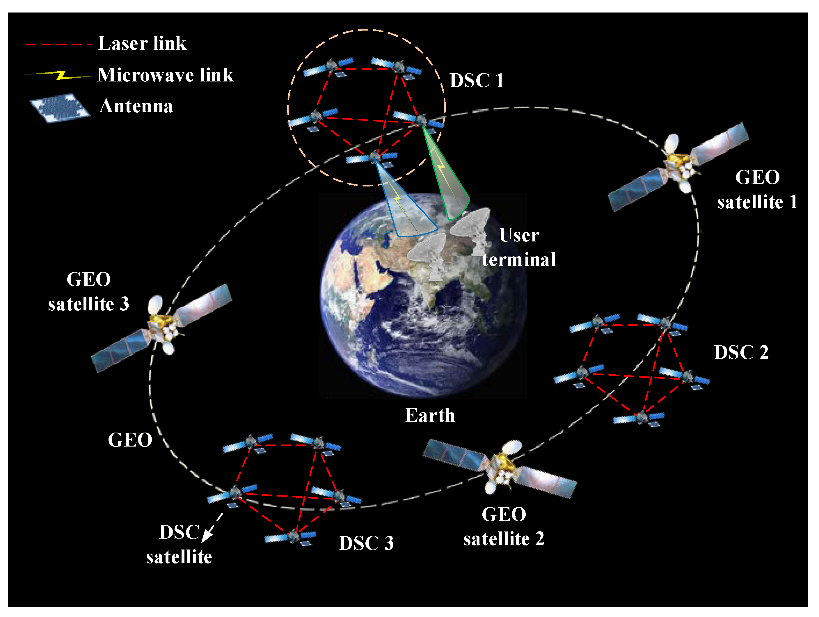
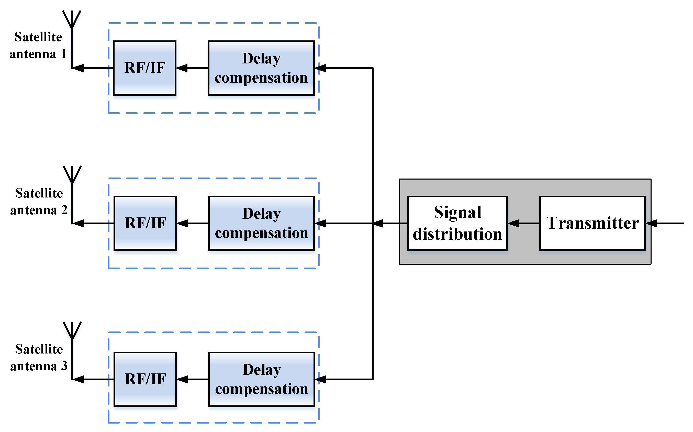
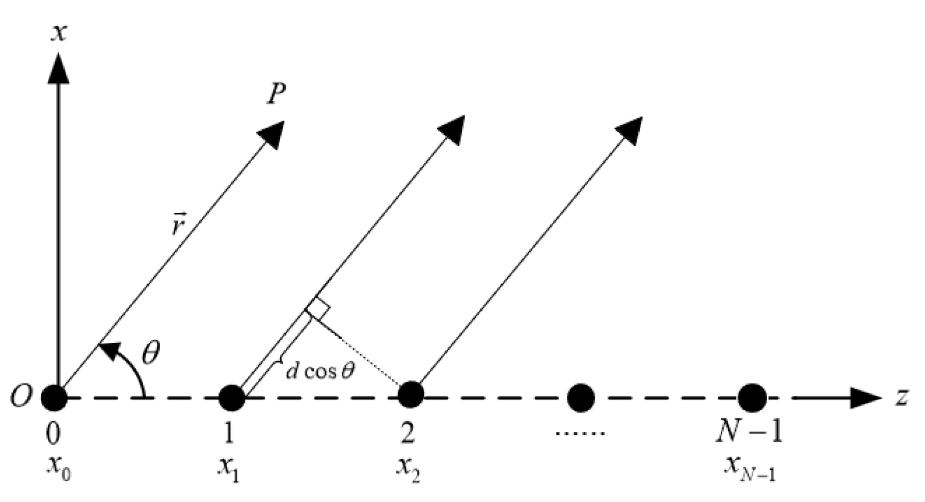
  • We established a distributed antenna cooperative transmission scenario for DSC systems, utilizing multiple DSC satellites equipped with antennas operating in the same frequency band. Moreover, we present the cooperative transmission principles of DSC distributed antennas at both the satellite and ground ends. Furthermore, mathematical expressions for the synthesis of far-field signal strength and the far-field antenna pattern of DSC distributed antennas are provided.
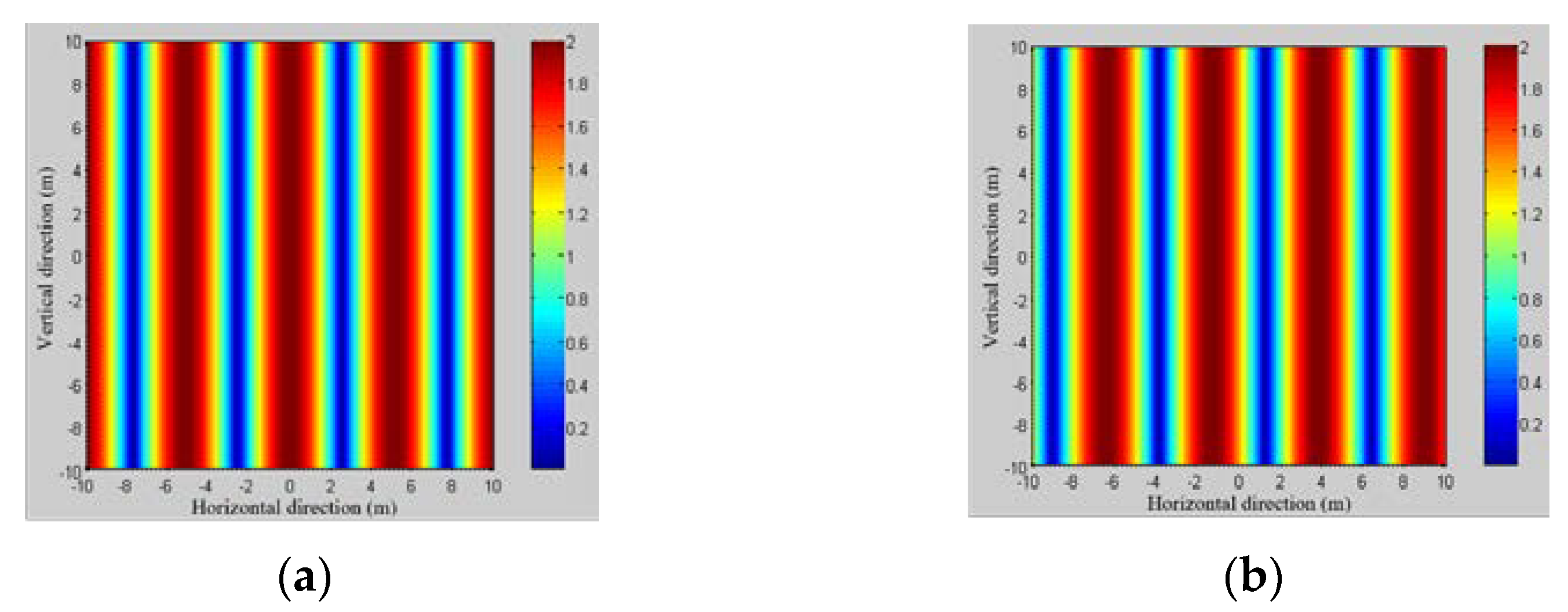
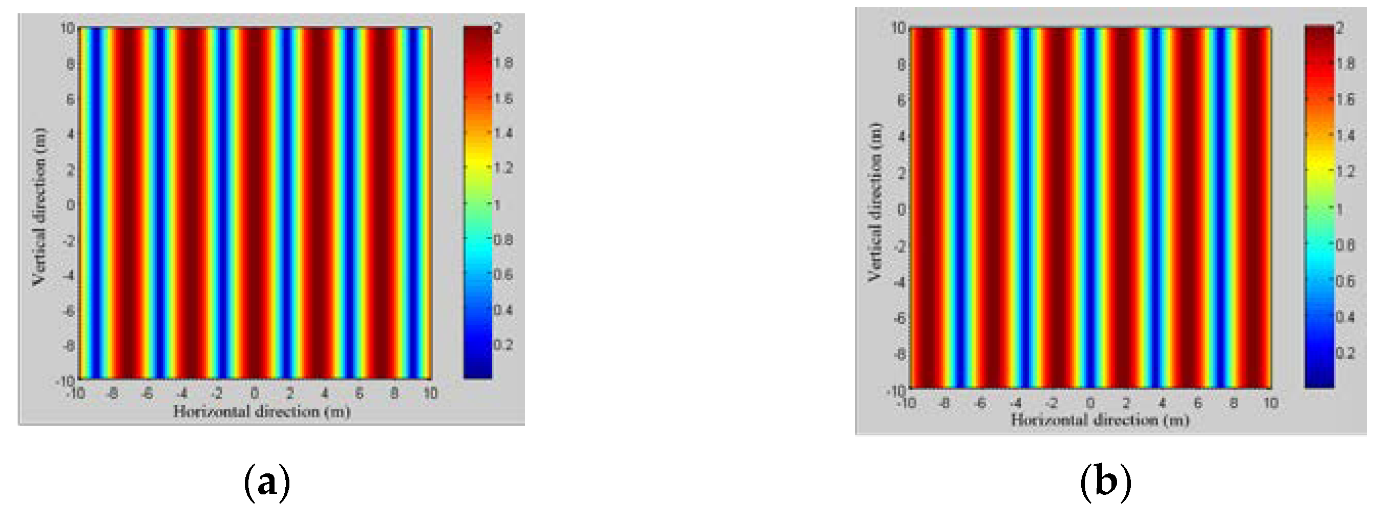
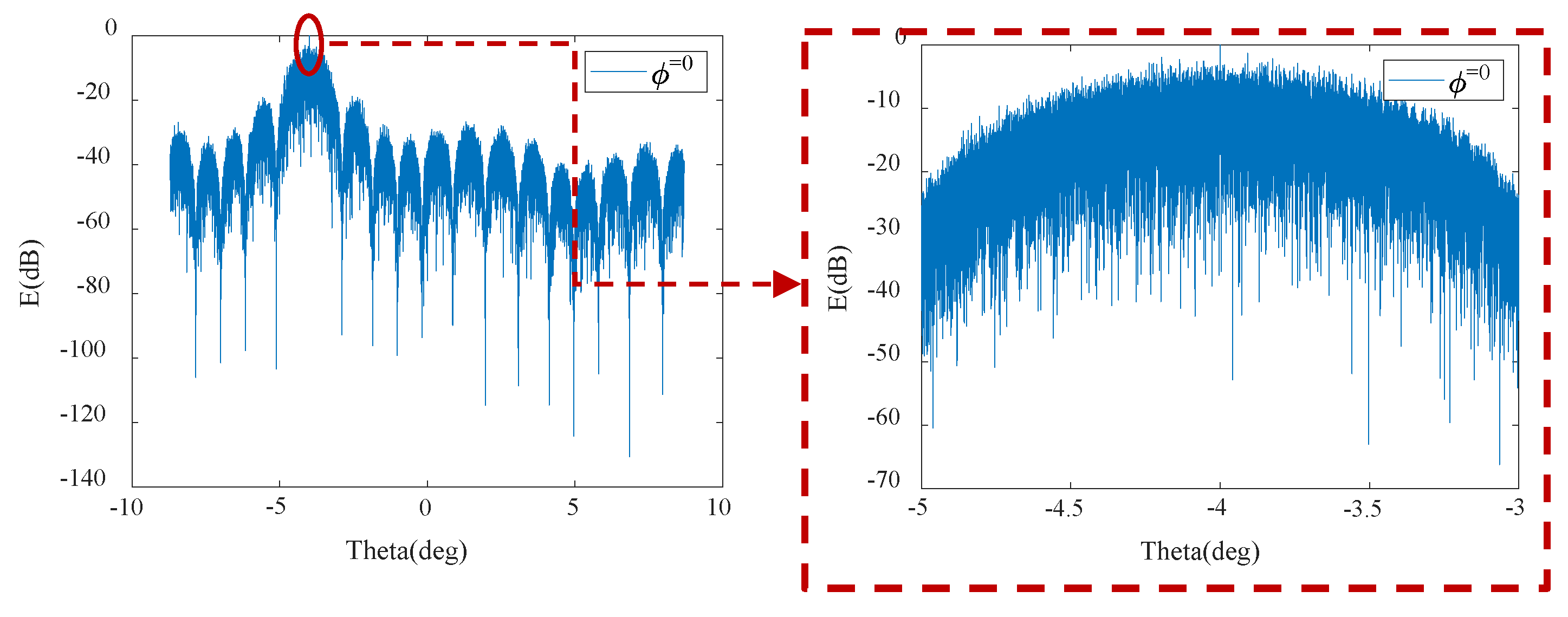
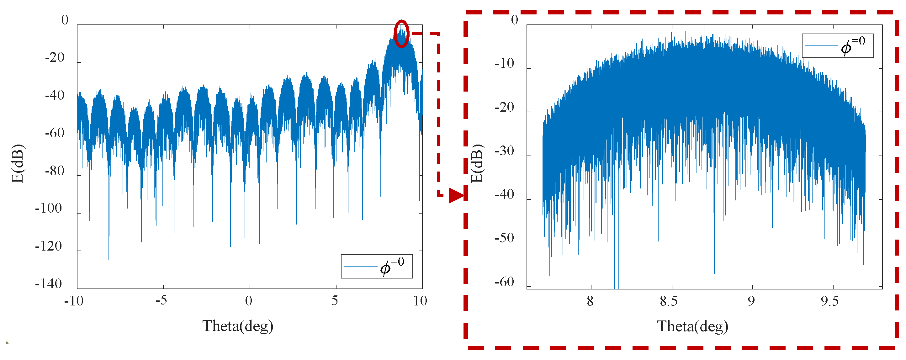
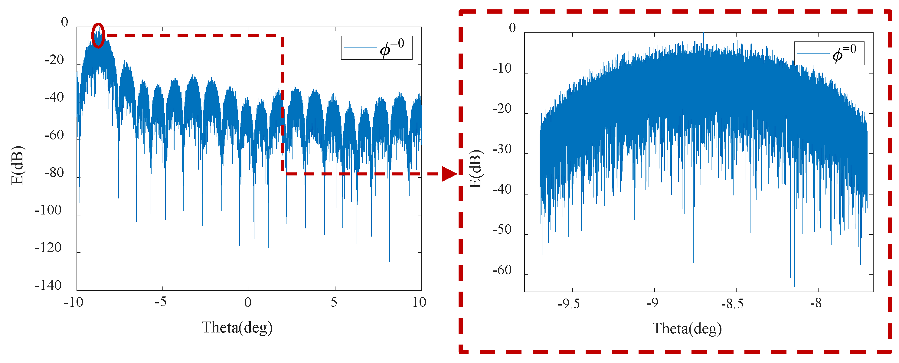
  • Considering the grating lobe effect of DSC distributed antennas during the cooperative transmission process, a simulation analysis was conducted on the far-field pattern of DSC distributed antennas by changing the relative positions and carrier phases of the distributed antennas in the scenario of two DSC satellites. The simulation results indicate that the relative positions of the satellites will affect the interference patterns, and changes in the carrier phase will result in the translation of interference patterns.
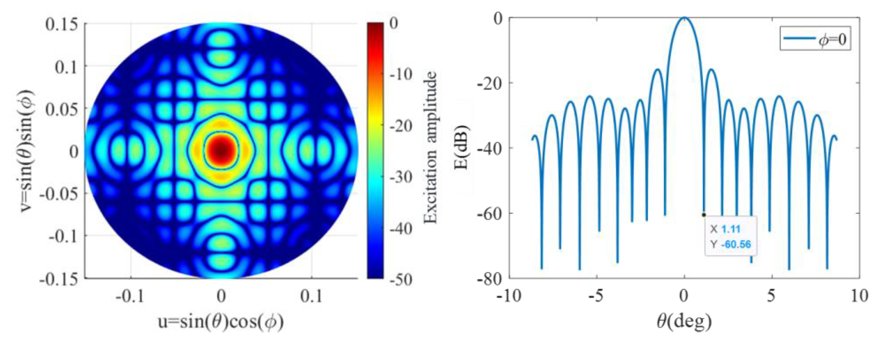
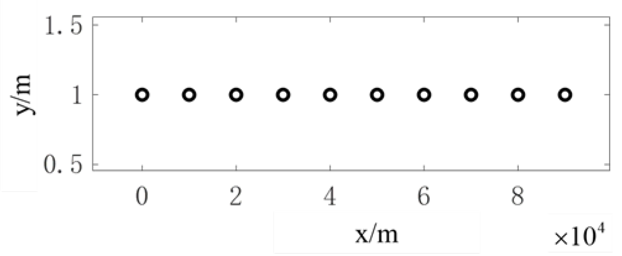
  • In order to effectively avoid the occurrence of grating lobes, we considered each individual DSC satellite as an antenna element, while the satellites themselves formed a super-sparse array with a non-periodic arrangement. The antenna patterns of two different array layouts, namely, uniform and non-periodic arrangements of 10 satellites in clusters, were simulated and analyzed. The simulation results indicate that non-periodic array can mitigate the appearance of grating lobes, but it disperses the energy of the grating lobes into the sidelobe region, resulting in an overall increase in the sidelobe level. To control the overall sidelobe level, further optimization of the layout is required.
The remaining sections of this paper are organized as follows. Section 2 introduces the scene model and array configuration of the DSC distributed antenna. Section 3 analyzes the impact of grating lobes by simulating the grating lobes formed by two DSC distributed antenna arrays and proposes grating lobe suppression strategies. In Section 4, the grating lobes formed by the beamforming of 10 satellites in the distributed satellite clusters are suppressed using a non-periodic arrangement. Finally, Section 5 provides a summary of this paper.

2. DSC Distributed Antenna Cooperative Transmission

2.1. Scenario Modelling

The DSC consists of a set of lightweight satellites in GEO distributed in the same or adjacent orbit, as shown in Figure 1, with each node of the satellites in the DSC sharing a GEO position of less than 1°. To prevent collisions and ensure safe communication, the minimum distance between the DSC satellites was maintained at 15 km or more, and a multi-satellite co-location strategy was employed. The type and aperture of the antennas carried on DSC satellites can vary and may include array antennas or reflective surface antennas. By integrating multiple DSC satellite antennas and ground antennas, a distributed MIMO system can be established, which utilizes spatial diversity and gain multiplexing to enhance the system capacity and antenna gain [7]. Each DSC satellite antenna can transmit and receive data independently, enabling the system to handle multiple data streams simultaneously. The distributed MIMO system can also boost channel capacity and antenna performance by combining the received signals from multiple antennas and facilitating cooperative transmission from DSC distributed antennas. With inter-satellite synchronization techniques, the antenna beams of N DSC satellites can be synthesized in-phase on-satellite and on the ground, resulting in a higher ratio of antenna gain G to the equivalent noise temperature T of the receiving system ( G / T value) and equivalent omnidirectional radiated power ( E I R P ) in the satellite communication link. The DSC distributed antenna uses multiple antennas distributed on different DSC satellites to receive signals from the same source, the received signals are amplified by low noise amplifiers, and then the radio frequency (RF) signals are transformed into intermediate frequency (IF) signals by a down-converter, followed by a series of operations of signal alignment and synthesis, carrier tracking, subcarrier tracking, and symbol synchronization to achieve the synthesis of the signals received by each antenna; thus, the signal-to-noise ratio of the received signal is improved and a reliable and useful signal is obtained [14].
For the uplink of the signal, a block diagram of the received signal synthesis scheme of the DSC distributed antenna system is given in Figure 2. Each satellite antenna that forms part of the DSC distributed antenna system can not only work individually, but can also perform DSC distributed antenna arraying to complete the received signal synthesis. During the DSC distributed antenna arraying, the antennas on each satellite receive signals from the same client, and the RF/IF converter module (RF/IF) in each antenna downconverts the received RF signal to an IF signal. Delay compensation is applied to the IF signal from each antenna and the amount of delay compensation is roughly calculated using the geometry of the DSC satellite in relation to the client. The delay-compensated IF signals are further determined by inter-correlation operations between each other, and this is used to compensate the delay residuals for the IF signals, which are then synthesized. For the downlink of the signal, a block diagram of the transmit signal synthesis scheme for the DSC distributed antenna system is given in Figure 3. The transmitter compensates the IF signal for the delay and the amount of delay compensation is calculated by the geometrical relationship between the satellite and the user side. The delay-compensated IF signal is converted into an RF signal by the RF/IF converter module, which is then radiated by each antenna, resulting in signal synthesis on the same user side.

2.2. Antenna Arraying

Combining multiple DSC satellite antennas together to achieve a DSC distributed antenna array provides a wider bandwidth and enhanced signal strength and channel capacity, which can improve the antenna performance and reliability of transceiver signals. Changing the geometric layout of the DSC distributed antenna, such as the orbital height of the satellite antenna, the relative position of the satellites, and the carrier phase, will have an impact on the performance of the DSC distributed antenna array. Depending on the application requirements, DSC distributed antenna arrays can also be flexibly configured and adapted to suit different communication scenarios and environments. For example, for communication scenarios requiring wide coverage, multiple DSC satellite antennas can be configured to achieve higher signal coverage and better communication quality. For scenarios requiring high-speed mobile communications, multiple DSC satellite antenna sets can be configured as one large virtual antenna to achieve better signal tracking and transmission speed.
The most significant advantage of the DSC distributed antenna array is its ability to achieve an E I R P value N 2 times greater than that of a single antenna. For example, in a binary array, two antennas transmit a sinusoidal signal with the same polarization mode and a carrier frequency of f . The far-field synthesized signal strength E ( t ) can be calculated as the following [15]:
E ( t ) = e 1 cos ( 2 π f t + φ 1 ) + e 2 cos ( 2 π f t + φ 2 )
In Equation (1), e 1 , e 2 are the electric field strengths of the respective signals emitted by the two antennas; φ 1 , φ 2 are the corresponding carrier phases. Assuming e 1 = e 2 = e , only the effect of the phase difference is analyzed.
If φ 1 = φ 2 = 0 , then
E ( t ) = 2 e cos ( 2 π f t + φ )
The two signals are coherently superimposed and the amplitude of the received signal from the target spacecraft becomes twice as large and the power becomes four times as large. If the phase φ 1 = φ 2 + π , then E ( t ) = 0 , at which point the two signals cancel each other out.
For the more general case of having N antennas, the signal strength achieved in the far field can be expressed as the following:
E ( t ) = i = 1 N e i cos ( 2 π f t + φ i )
In Equation (3), e i and φ i represent the signal strength and carrier phase of the transmitted signal from each antenna, respectively.
From the perspective of the antenna pattern, a single antenna pattern can be obtained through the Fourier transform of the antenna’s near-field distribution. Assuming that the normalized distribution function is an ideal circular distribution, the far-field antenna pattern E can be obtained by the following [16]:
E = a exp ( j k ρ 2 2 r ) j ρ J 1 ( k a ρ r )
In Equation (4), a denotes the antenna radius; r represents the target distance; k = 2 π / λ is the wave number; and J 1 refers to the first-order Bessel function.

3. Analysis of Grating Lobes in DSC Distributed Antennas

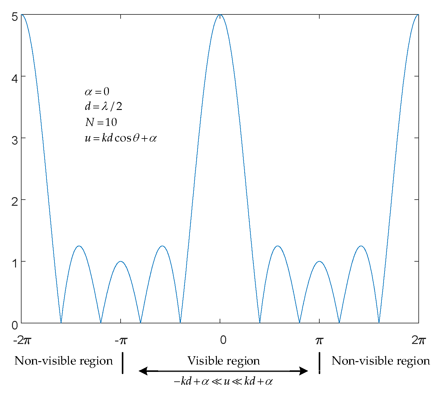
3.1. Grating Lobe Effect

DSC distributed antennas, as a type of ultra-sparse array, generate numerous grating lobes after beamforming. Figure 4 illustrates the element distribution of an N elements linear array, with individual element excitation denoted by w 0 , w 1 , w 2 , , w N 1 . Assume that each element is an isotropic point source and the array factor pattern represents the total field pattern. However, if the elements in the array are not point sources, the total field pattern needs to be obtained using the principle of pattern multiplication, where the array factor is multiplied by the element pattern. The array factor expression for this linear array is as the following [17]:
A f = ( w 0 + w 1 e j ( k x 1 cos θ x ) + w 2 e j ( k x 1 cos θ x ) + + w N 1 e j ( k x N 1 cos θ x ) ) = n = 0 N 1 I n e j k x n cos θ x + α n
where w n = I n e j α n represents complex excitation and k = 2 π / λ . It can be observed that the array factor is dependent on the number of elements N , the spatial distribution of the elements x n , and the excitation of the elements w n (including amplitude and phase). In general, arrays have a large number of elements, and if the element pattern lobes are wide, the radiation characteristics of the array can be approximated by studying the radiation characteristics of the array factor. If the excitation amplitudes of the elements in the array are the same I 0 , there exists a uniform progressive phase difference α 0 between adjacent elements, i.e., w n = I 0 e j n α 0 , n = 0 , 1 , 2 , , N 1 , and they are uniformly spaced with a distance d between adjacent elements, i.e., x n = n d , then the array is a uniform linear array. Taking the position of element 0 as the coordinate origin, the array factor function for this array is given by the following:
A f = n = 0 N 1 I 0 e j n k d cos θ α 0
In Equation (6), the angle θ represents the angle between the radial vector r from reference point O to the far-field point P and the horizontal line Z -axis. If the angle θ is measured with respect to the normal X -axis of r and the horizontal line, then Equation (6) can also be expressed as the following:
A f = n = 0 N 1 I 0 e j n k d sin θ α 0
For Equation (6), let u = k d cos θ α . The array factor function can be written as the following:
A f = n = 0 N 1 I 0 e j n u
The summation is a geometric series, which can be further simplified.
A f = I 0 n = 0 N 1 e j n u = I 0 1 + e j u + e j 2 u + + e j ( N 1 ) u = I 0 1 e j N u 1 e j u = I 0 e j N u 2 e j u 2 sin N u 2 sin u 2
If the coordinate origin of the array is established at the center position, the result of Equation (9) is the following [15]:
A f = I 0 sin N u 2 sin u 2
As u approaches 0 and ± n π , the A f tends to I 0 N , and the value at this point is the maximum. Therefore, the normalized array factor for a uniform linear array is given by
A f n = A f max A f = sin N u 2 N sin u 2
Taking the modulus operation of Equation (11), we obtain the normalized array factor directional pattern function:
A f n = sin N u 2 N sin u 2
From Equation (10), it can be observed that the array factor is a function of u , which is a periodic function with a period of 2 π . The range of u extends throughout the entire real number line. However, in an actual array, the range of θ is limited to the interval 0 , π , corresponding to a variation range of k d α , k d α for u . This range is known as the visible region, while the regions outside this range are considered invisible. Therefore, the phase α can be used to control the initial position of the visible region and hence move the visible region, while the inter-element spacing d controls the size of the visible region.
As shown in Figure 5, the schematic diagram illustrates the visible region of a 5-element uniform linear array. For the expression A f n = sin N u / 2 N sin k u / 2 , due to the limited range of u , the theoretically possible regions do not exist in practice. In engineering applications, it is important to avoid the occurrence of grating lobes within the visible region.
The main lobe of the array factor reaches its maximum value at u = 0 . Since the array factor A f ( u ) is a periodic function with a period of 2 π , the maximum value also occurs periodically, specifically, when u = 2 m π , m = 0 , ± 1 , ± 2 , When m = 0 , u = 0 , it corresponds to the main lobe, while for other values of m , it corresponds to the side lobes [18]. The presence of side lobes leads to a decrease in gain, dispersion of radiated energy, and can result in erroneous target localization and direction finding, making it necessary to suppress them. Based on the concept of the visible region mentioned earlier, the actual range of u is finite. Therefore, by limiting the range of the visible region to 2 π , the occurrence of side lobes can be avoided. For arbitrary beam pointing, the condition for side lobe suppression is the following [15]:
u max = k d cos θ cos θ m max < 2 π
Since θ = 0 ~ π , cos θ cos θ m max = 1 + cos θ m , therefore
d < λ / 1 + cos θ m
This equation can also serve as a condition for the absence of grating lobes in non-uniform linear arrays (such as Taylor arrays, Chebyshev arrays, etc.).

3.2. Two Satellite Antennas

The most significant difference between DSC distributed antennas and traditional satellite-based distributed antennas lies in the distance between satellites. As shown in Figure 6, assume that in the satellite orbit altitude H = 3.6 × 10 4 km, two satellite antenna aperture diameters are 1 m, with an operating frequency of f = 30 GHz, for an analysis in the ground of a 20 × 20 m2 area, the satellite different distance, and a different phase interference situation. When two antennas in a binary array radiate electromagnetic waves in the same direction at the same time, the intensity of the electric field received at different locations in space will be affected by different phases, so interference will occur. As shown in Figure 7 and Figure 8, we simulated the interference of the far-field antenna pattern after the satellite antennas were grouped in the array at distances of 70 km and 100 km between the two satellites, respectively. Through the analysis of the two satellite antenna simulations, we found that the far-field antenna patterns of the two satellite antenna arrays formed obvious interference fringes. At the center of the two antennas’ radiation signal coherent superposition, the electric field strength at this point was twice as strong as the single antenna radiation, and the synthesis power was four times the power of the single antenna signal. On the one hand, when changing the antenna carrier phases φ 1 and φ 2 , the interference fringes will pan, reflecting the impact of the change in antenna phase difference on the power synthesis; therefore, for a certain direction of the field strength size, and where each antenna signal phase alignment is related, adjusting the phase difference between the antennas can change the size of the synthetic power in a certain direction. On the other hand, when changing the relative position of the antennas d increases, the interference fringes become narrower and the number of fringes increases, reflecting the effect of the change in antenna position on the power synthesis.

3.3. Grating Lobe Suppression

As analyzed in the previous section, distributed antennas, as a type of ultra-sparse array, produce a large number of grating lobes after beamforming, which requires careful consideration of their impact. There are two approaches for mitigating grating lobes: one is to suppress them in the spatial domain and the other is to suppress them in the signal domain.

3.3.1. Spatial Grating Lobe Suppression

The suppression of spatial grating lobes is primarily achieved through the design of ultra-sparse and non-uniform antenna array layouts, which break the periodicity of uniform arrays and eliminate the grating lobes [19,20]. The antenna layout can be either a linear or planar array. Various intelligent optimization algorithms are employed to optimize the antenna positions as design variables. Simulation results indicate that when the baseline length of the satellite array remains constant, the variation in the number of satellites significantly affects the sidelobe level of the beam, while the impact of the minimum satellite spacing on the sidelobe level is not significant. Table 1 presents the optimized sidelobe levels for different values of the number of satellites N and minimum satellite spacing d c . It is worth noting that the effectiveness of this method in suppressing grating lobes comes at the cost of increasing the number of satellites.

3.3.2. Signal Domain Grating Lobe Suppression

Considering the signal entering the grating lobe as interference, methods from the radar signal processing field can be applied to suppress the grating lobe in the signal domain. For instance, techniques such as deconvolution [21], cascaded Doppler filtering for beamforming [22], and frequency orthogonal signal deblurring can be employed to eliminate the interference caused by the grating lobe signal. Further analysis and research are required to examine the impact of these methods on communication signals. It is important to note that these methods come at the expense of increased signal processing requirements.

4. Suppression of Grating Lobes Using Sparse Arrays

4.1. Layout of a Single Satellite Antenna Array

For the purpose of achieving a compact and fewer element configuration with the ability to achieve wide-angle scanning for a single DSC satellite antenna in GEO orbit, the layout of the single satellite array adopts an equilateral triangular arrangement as shown in Figure 9. Taking the transmitting antenna as an example, the operating frequency was set to 20 GHz and the triangular side length was set to d x = 2.4 λ . The array pattern of the single satellite, as shown in Figure 10, exhibited no grating lobes within the range of ± 8.7 . The sidelobe level was 15.88 dB, and the main lobe width was 2.22 , enabling improved directivity and extended transmission distance.

4.2. Distributed Antenna Array for DSC

4.2.1. Uniform Array

As shown in Figure 11, we first considered the case of using a uniformly spaced linear array of 10 GEO DSC satellites as an array configuration for the DSC distributed antenna. According to antenna theory, the antenna pattern after arraying is equal to the array factor of the 10-element linear array layout multiplied by the array pattern of the GEO array. We took the minimum spacing of the GEO satellites to be 10 km. From the antenna pattern in Figure 12, it is not difficult to observe that there are many grating lobes present within the main lobe of the GEO array due to the large difference between the beamwidth of the array factor (approximately 1.8 × 10 5 ) and that of a single GEO satellite array ( 2.22 ).

4.2.2. Sparse Array

As shown in Figure 13, in order to suppress the grating lobes, a sparse linear array configuration was adopted with a minimum distance of 10 km and an aperture of 120 km. When the scanning angle was 0 , it could be observed from Figure 14 that the grating lobes were effectively suppressed, but the sidelobe level decreased by 2.09 dB and the beamwidth was 1.4 × 10 5 .
In the following, the array was scanned and the antenna orientation diagrams are shown in Figure 15, Figure 16, Figure 17 and Figure 18 when the scanning angles θ were considered to be ± 4 and ± 8.7 , respectively. The sidelobe levels and beamwidths are presented in Table 2. From the simulation results, it can be observed that in distributed satellite clusters, where antennas are placed on each satellite and the inter-satellite spacing is much larger than the operating wavelength, a single satellite can be regarded as an antenna element, while the satellites collectively form an ultra-sparse array (distributed array). If a uniform layout is adopted, numerous grating lobes will appear. To avoid grating lobes, a non-periodic arrangement can be employed. Non-periodic arrays suppress the occurrence of grating lobes, but disperse their energy into the sidelobe region, leading to an overall increase in sidelobe levels. To control the overall sidelobe level, optimization of the layout approach can be implemented.

5. Conclusions

Satellite-based distributed antenna technology enables flexible configuration and deployment according to practical needs and scenarios, thereby enhancing system flexibility and scalability. It holds significant importance and promising prospects in modern satellite communication systems. In this paper, we analyzed the impact of grating lobes on distributed satellite communication (DSC) distributed antennas. We conducted simulation analyses of the grating lobes in the far-field pattern of the antenna array by altering the relative positions of the satellite antennas and the carrier phase of the satellite terminals in two DSC satellite scenarios. The simulation results indicated that the relative positions of the satellites had an influence on the interference fringes, while changing the carrier phase of the antennas resulted in the translation of the interference fringes. To suppress the formation of grating lobes, we adopted a sparse linear array configuration and compared it with a uniform linear array’s antenna pattern. Simulation results indicated that the non-periodic array can push the occurrence of grating lobes further away, but it disperses the energy of the grating lobes into the sidelobe region, resulting in an overall increase in sidelobe levels. In this study, the sidelobe level of the distributed antennas decreased by 13.79 dB compared to that of a single satellite antenna. Therefore, to control the overall sidelobe level, further optimization of the array configuration is necessary.

Author Contributions

Conceptualization, Y.H. and C.W.; methodology, Y.H.; software, C.W.; validation, Y.H. and C.W.; formal analysis, C.W and C.Q.; investigation, C.W.; resources, C.W.; writing—original draft preparation, C.W.; writing—review and editing, Y.H.; visualization, C.Q.; supervision, Y.H.; project administration, Y.H.; funding acquisition, Y.H. All authors have read and agreed to the published version of the manuscript.

Funding

This research received no external funding.

Data Availability Statement

The dataset is not applicable.

Conflicts of Interest

The authors declare no conflict of interest.

References

  1. He, Y.; Wang, C. Optimization Design for Sparse Planar Array in Satellite Communications. Electronics 2023, 12, 1763. [Google Scholar] [CrossRef]
  2. Merlo, J.M.; Mghabghab, S.R.; Nanzer, J.A. Wireless Picosecond Time Synchronization for Distributed Antenna Arrays. IEEE Trans. Microw. Theory Tech. 2023, 71, 1720–1731. [Google Scholar] [CrossRef]
  3. Awan, W.A.; Naqvi, S.I.; Ali, W.A.E.; Hussain, N.; Iqbal, A.; Tran, H.H.; Alibakhshikenari, M.; Limiti, E. Design and realization of a frequency reconfigurable antenna with wide, dual, and single-band operations for compact sized wireless applications. Electronics 2021, 10, 1321. [Google Scholar] [CrossRef]
  4. Alibakhshikenari, M.; Virdee, B.S.; See, C.H.; Shukla, P.; Moghaddam, S.M.; Zaman, A.U.; Shafqaat, S.; Akinsolu, M.O.; Liu, B.; Yang, J.; et al. Dual-polarized highly folded bowtie antenna with slotted self-grounded structure for sub-6 GHz 5G applications. IEEE Trans. Antennas Propag. 2021, 70, 3028–3033. [Google Scholar] [CrossRef]
  5. Tuzi, D.; Delamotte, T.; Knopp, A. Satellite Swarm-Based Antenna Arrays for 6G Direct-to-Cell Connectivity. IEEE Access 2023, 11, 36907–36928. [Google Scholar] [CrossRef]
  6. Hasnain, S.N.; Stephan, R.; Brachvogel, M.; Michael, M.; Hein, M.A. Performance of distributed antenna sub-arrays for robust satellite navigation in automotive applications. Eur. J. Navig. 2019, 19, 11–18. [Google Scholar]
  7. Li, C.; Zhu, H.; Cai, J.; Hu, J.; Li, G.; Li, G. Capacity analysis of terrestrial antenna array in distributed satellite MIMO communication system. IEEE Trans. Veh. Technol. 2021, 70, 4435–4450. [Google Scholar] [CrossRef]
  8. Zhou, D.; Sheng, M.; Li, B.; Li, J.; Han, Z. Distributionally robust planning for data delivery in distributed satellite cluster network. IEEE Trans. Wirel. Commun. 2019, 18, 3642–3657. [Google Scholar] [CrossRef]
  9. Dolgopolov, A.V.; Smith, P.M.; Stroup, T.; Christensen, C.B.; Starzyk, J.; Jones, T. Analysis of the Commercial Satellite Industry, Key Indicators and Global Trends. In Proceedings of the ASCEND 2020, Las Vegas, NV, USA, 16–18 November 2020; p. 4244. [Google Scholar]
  10. Peng, C.; He, Y.; Zhao, S.; Song, L.; Deng, B. Integration of Data Center Into The Distributed Satellite Cluster Networks: Challenges, Techniques, And Trends. IEEE Netw. 2022, 37, 52–58. [Google Scholar] [CrossRef]
  11. He, Y.; Sheng, B.; Yin, H.; Liu, Y.; Zhang, Y. Distributed Satellite Cluster Laser Networking Algorithm with Double-Layer Markov DRL Architecture. Space Sci. Technol. 2023, 3, 0012. [Google Scholar] [CrossRef]
  12. Mghabghab, S.; Ouassal, H.; Nanzer, J.A. Wireless frequency synchronization for coherent distributed antenna arrays. In Proceedings of the 2019 IEEE International Symposium on Antennas and Propagation and USNC-URSI Radio Science Meeting, Atlanta, GA, USA, 7–12 July 2019; pp. 1575–1576. [Google Scholar]
  13. Jones, D.L. Weak-Signal Phase Calibration Strategies for Large DSN Arrays. In Proceedings of the 2005 IEEE Aerospace Conference, Big Sky, MT, USA, 5–12 March 2005; pp. 1150–1157. [Google Scholar]
  14. Mileant, A.; Hinedi, S. Overview of Arraying Techniques in the Deep Space Network. In The Telecommunications and Data Acquisition Report; NASA: Washington, DC, USA, 1991. [Google Scholar]
  15. Balanis C, A. Antenna Theory: Analysis and Design; John Wiley & Sons: Hoboken, NJ, USA, 2016. [Google Scholar]
  16. Tang, T.; Su, W.; Han, Y.; Li, J. Research on Spatial Power Combining Efficiency of High Power Radar. Radar Sci. Technol. 2013, 11, 325–328. [Google Scholar]
  17. Daly, M.P.; Bernhard, J.T. Directional modulation technique for phased arrays. IEEE Trans. Antennas Propag. 2009, 57, 2633–2640. [Google Scholar] [CrossRef]
  18. Delos, P.; Broughton, B.; Kraft, J. Phased array antenna patterns—Part 2: Grating lobes and beam squint. Analog. Dialogue 2020, 54, 1–4. [Google Scholar]
  19. Zhu, J.; Lei, P.; Wang, J.; Zhang, Y.; Yuan, C. Grating Lobe Suppression and Angle Estimation Based on Virtual Antennas Filling in Sparse Array. IEEE Antennas Wirel. Propag. Lett. 2022, 22, 502–506. [Google Scholar] [CrossRef]
  20. Barott, W.C.; Steffes, P.G. Grating lobe reduction in aperiodic linear arrays of physically large antennas. IEEE Antennas Wirel. Propag. Lett. 2008, 8, 406–408. [Google Scholar] [CrossRef]
  21. Dillon, J. Grating lobe prediction and deconvolution for synthetic aperture sonar. J. Acoust. Soc. Am. 2018, 144 (Suppl. S3), 1685. [Google Scholar] [CrossRef]
  22. Hua, G.; Abeysekera, S.S. Receiver design for range and Doppler sidelobe suppression using MIMO and phased-array radar. IEEE Trans. Signal Process. 2012, 61, 1315–1326. [Google Scholar] [CrossRef]
Figure 1. DSC distributed antenna scenario modelling.
Applsci 13 10912 g001
Figure 2. Block diagram of received signal synthesis scheme for DSC distributed antenna system.
Applsci 13 10912 g002
Figure 3. Block diagram of the DSC distributed antenna system transmit signal synthesis scheme.
Applsci 13 10912 g003
Figure 4. Distribution of the N units linear array element.
Applsci 13 10912 g004
Figure 5. A schematic diagram of the visible region for a 5-element uniform linear array.
Applsci 13 10912 g005
Figure 6. Distribution of the two satellites.
Applsci 13 10912 g006
Figure 7. Interference in the far-field antenna pattern when the two satellites are at a distance of 70 km: (a) φ 1 = 0 , φ 2 = 0 ; (b) φ 1 = 0 , φ 2 = 90 .
Applsci 13 10912 g007
Figure 8. Interference in the far-field antenna pattern when the two satellites are at a distance of 100 km: (a) φ 1 = 0 , φ 2 = 0 ; (b) φ 1 = 0 , φ 2 = 90 .
Applsci 13 10912 g008
Figure 9. Layout of a single DSC satellite antenna array in GEO.
Applsci 13 10912 g009
Figure 10. Antenna pattern of a single DSC satellite antenna array in GEO.
Applsci 13 10912 g010
Figure 11. The arrangement of 10 DSC satellites in a uniform linear array configuration.
Applsci 13 10912 g011
Figure 12. The antenna pattern of a uniform linear array configuration with 10 DSC satellites.
Applsci 13 10912 g012
Figure 13. The arrangement of 10 DSC satellites in a sparse linear array configuration.
Applsci 13 10912 g013
Figure 14. The antenna pattern of a sparse array configuration with 10 DSC satellites.
Applsci 13 10912 g014
Figure 15. The antenna pattern at a scanning angle of 4 .
Applsci 13 10912 g015
Figure 16. The antenna pattern at a scanning angle of 4 .
Applsci 13 10912 g016
Figure 17. The antenna pattern at a scanning angle of 8.7 .
Applsci 13 10912 g017
Figure 18. The antenna pattern at a scanning angle of 8.7 .
Applsci 13 10912 g018
Table 1. Sidelobe levels (dB) of an optimized beam for different values of N and dc in an array.
d c (m) N = 8 N = 16 N = 24
1001.64.546.1
1201.724.356.2
1401.804.60
1601.774.37
Table 2. Sidelobe levels (dB) and beamwidths (∘) corresponding to different scanning angles.
Scanning Angle ( θ ) 0 ± 4 ± 8.7
Sidelobe   Level   ( d B )
Beamwidth   ( )
2.09
1.4 × 10 5
1.59
1.4 × 10 5
1.55
1.4 × 10 5
Disclaimer/Publisher’s Note: The statements, opinions and data contained in all publications are solely those of the individual author(s) and contributor(s) and not of MDPI and/or the editor(s). MDPI and/or the editor(s) disclaim responsibility for any injury to people or property resulting from any ideas, methods, instructions or products referred to in the content.

