Article

The Design of a Video Reflection Removal Method Based on Illumination Compensation and Image Completion Fusion

1
School of Transportation and Vehicle Engineering, Shandong University of Technology, Zibo 255000, China
2
Collaborative Innovation Center of New Energy Automotive, Shandong University of Technology, Zibo 255000, China
*
Author to whom correspondence should be addressed.
Appl. Sci. 2023, 13(19), 10913; https://doi.org/10.3390/app131910913
Submission received: 10 September 2023 / Revised: 23 September 2023 / Accepted: 29 September 2023 / Published: 1 October 2023

Abstract

:
Our objective is to develop a video reflection removal algorithm that is both easy to compute and effective. Unlike previous methods that depend on machine learning, our approach proposes a local image reflection removal technique that combines image completion and lighting compensation. To achieve this, we utilized the MSER image region feature point matching method to reduce image processing time and the spatial area of layer separation regions. In order to improve the adaptability of our method, we implemented a local image reflection removal technique that utilizes image completion and lighting compensation to interpolate layers and update motion field data in real-time. Our approach is both simple and efficient, allowing us to quickly obtain reflection-free video sequences under a variety of lighting conditions. This enabled us to achieve real-time detection effects through video restoration. This experiment has confirmed the efficacy of our method and demonstrated its comparable performance to advanced methods.

1. Introduction

Reflection removal involves separating the layers of an image into the background and reflection layers. There are various methods for removing reflections, including single image reflection removal (SIRR) [1,2,3,4,5,6,7,8,9,10,11,12,13,14,15], multi-image reflection removal [16,17,18,19,20,21], video reflection removal [22,23,24,25], light field camera reflection removal [26,27,28,29], and special function camera (sensor) reflection removal [30,31]. The image removal model is shown in Figure 1.
Recent research has revealed that machine learning networks [9,10] that are designed well can learn the distinguishing features of specific reflection removal methods from a vast amount of training set data. For instance, by using image features for the semantic segmentation of images [6] or extracting core modules for reflection dynamics [5], usually from VGG networks, these networks can better predict the movement of the background and reflection layers and suggest image reflection parts. Typically, prediction is carried out in two stages [7,9,11]. In another study, a solution was proposed to minimize the issue of under/over exposed pixels in captured images. This was achieved by using multiple polarized images taken at different exposure times [16] and introducing the weighted non-negative matrix decomposition of full change regularization. It should be noted, however, that these methods often require a longer sample training time.
In this paper, we provide a method for removing reflection layer areas from videos that does not require training. It uses an image completion strategy and a lighting correction mechanism. This process has two essential components: (1) The recognition of reflection regions, which compares the two video frames before and after the region and lowers the error rate of recognition by using a lighting correction technique; (2) Pixel substitution methods in the reflection removal process in order to cover the intended reflection area and make the reflection removal procedure simpler. The target area recognition step of this method’s detection speed and reflection removal integrity may be guaranteed by coupling these two activities. In contrast to [4,16,26,28], our technique does not need the building of a complicated machine learning network or a substantial amount of sample training, and the process for acquiring pictures is also rather straightforward. Our contributions are summarized as follows:
(1)
We propose a video reflection removal method based on the combination of image complementation and illumination compensation, which has a 5.2% higher reflection region removal accuracy and operation speed than without adding illumination compensation.
(2)
We propose an illumination compensation mechanism based on a combination of luminance adjustment and gamma correction for reflective region extraction by joint MSER region matching.
The rest of this paper is organized as follows: In Section 2, we introduce an illumination compensation mechanism based on a combination of brightness adjustment and gamma correction, as well as a reflection region extraction method based on MSER region matching, with a focus on the reflection region removal method based on image completion and illumination compensation fusion. This paper analyzes the effectiveness of a reflection region removal method based on image completion and lighting compensation fusion. By comparing the image completion-based reflection region removal method with the relative motion-based reflection region removal method, the superiority of our method was found. In Section 3, we obtain the superiority of our method through comparative experiments.

2. Related Works

Single Image Reflection Removal (SIRR). Earlier researchers usually used a priori methods for image reflection removal, such as layer sparsity [2] and smoothing [3]. These methods mainly rely on the a priori asymmetry of the layers (reflection and background layers), and their applicability is limited by special cases. In recent years, machine learning-based reflection removal methods have prevailed. This approach learns the properties of specific reflection removal methods from a large training set of data by well-designed machine learning networks [4]. To facilitate the learning of the learning network, some auxiliary cues are generally used to help train the learning network. For example, using image features to extract the reflection dynamics core module [5], the module is typically extracted from a VGG network to better predict the motion of the background layer and the reflection layer and propose the image reflection part. Some methods use hybrid networks [15] for image deblurring or image enhancement, after which gradient information [1,4,6,7] and edge information [10] are explored; their information can be fused with reflection formation models [8] and Alpha hybrid masks [14], among others, to achieve the linear expression prediction of image reflections, generally choosing to use two stages [7,9,11] for prediction. Although machine learning-based methods achieve good results for radiation removal, they all try to solve the problem from the perspective of a single image.
Multi-image reflection removal. Multi-image reflection removal generally captures multiple images of a scene in a predefined manner, an operation that makes the reflection removal problem easier to handle. Most of the methods studied for multi-image reflection removal are based on motion cues [17,18,19], which exploit the difference in motion between two layers of images of the same target scene captured from different viewpoints. Some of the multi-image reflection removal methods adhered to the sparse non-negative matrix decomposition (NMF) optimization by combining a color illumination reflection model with NMF optimization in a multi-image framework [20]. According to the synthetic data of this method, the real data images of non-dielectric materials that are obtained conform to the proposed reflection model. Some of them also combine image information and multiscale gradient information with human perception-inspired loss functions [21] to accomplish reflection removal from images with machine learning. There are also some studies that use multiple polarized images taken at different exposure times in order to achieve high accuracy reflection removal in high dynamic range scenes [16] and minimize the under/over exposure pixel problem of the captured images by introducing a weighted non-negative matrix decomposition (WNMF) with full variation regularization. These multi-image methods lead to better reflection removal results due to the availability of image information from different viewpoints. However, the acquisition of images takes a long time and is professional, which limits the applicability of non-professional personnel.
Video reflection removal. Motion cues are also often used to handle video reflection removal [15,16,17,18,19,20,21,22]. Information about the relative displacement of the environment (i.e., reflection dynamics) captured in the image sequence and separated from the video frames is used to help image sequences separate reflection layers and reduce reflection artifacts using temporal coherence constraints. Some studies proposed a recursive method for reflection removal based on a prediction-correction model [25], which is able to effectively decompose the reflected image into different layers (reflection and background layers) according to the principle of a real centrifuge. Some studies separated reflections and dirt by averaging images through a priori algorithms [23], and others introduced optical flow into specular reflection removal methods with high-speed cameras and stroboscopes [24], using the optical flow method to compensate for the noise at the specified location of the specular reflection due to inter-frame differences when the high-speed camera moves. Unlike the real experimental video that contains both object and camera motion, our experiments only need to bring two frames of the image sequence in the video frame into the model and use the feature extraction method to extract the same region in both frames, as the reflection removal action range for reflection removal and the video reflection can be removed by the inter-frame difference method for changing reflection images.
Light field camera reflection removal. Although layer separation is irrelevant to conventional camera imaging, studies [26,27,28] demonstrate that light-field imaging can be beneficial to handle reflection removal. One study proposed a cue-no-reflection flash cue [27] to make distinguishing reflections easier for reflection removal and to avoid introducing artifacts in the presence of flash-only images when utilizing reflection-free cues by creating a specialized framework. Some of the studies have used reflection removal methods based on light field LF imaging [26,28], using epipolar plane images, retrieving scene depth maps from low frequency images, dividing the gradient points of the images into background and reflection layers based on the depth values, and reconstructing background images using sparse optimization methods. The drawback of the method proposed in the study above is that a special light field camera is required for reflection removal. By contrast, our proposed method uses a camera for environmental information acquisition without the flash processing of the acquired image, which can simplify the image data acquisition process.
Special function camera/sensor reflection removal. Special format images acquired by special cameras will have better results for the reflection removal of images. A study [30] proposed a learning framework-based reflection removal method for RGB images by directing the reflection suppression of active NIR images through a near-infrared (NIR) camera. There is also a study of reflection removal using data available on DP sensors [29]. This study simplifies the delineation of image gradients belonging to the background layer region by using out-of-focus-parallax cues that appear in the two sub-aperture views. However, most camera APIs currently do not provide access to this useful data, and the cost of this camera is high.

3. Method

This paper proposes a reflection removal method for black box videos based on the combination of image completion and illumination compensation. We use the gradient reconstruction and completion of transmitted images as a solution to the problem of reflection removal. Some of the reflected images in the video may shake due to vehicle bumps, and traditional feature matching region extraction methods cannot fully extract the target region. Based on the MSER feature region extraction method, we decompose the video into video frames and combine all of its frames into an image sequence. This article utilizes the phenomenon that the reflective imaging position and overall shape of the windshield do not change due to the driving of the vehicle and are only related to the direction of sunlight exposure. Different reflected images presented under different lighting conditions is compensated for through the addition of a loss function. Finally, the image is reconstructed using a motion gradient method through image completion to achieve the effect of reflection removal. Our approach comprises two key parts: (1) The extraction of the reflection region, which entails illumination adjustment and MSER region matching of the front and back picture frames; (2) The removal of reflections from images. Image differentiation is used together with the IRLS method and a penalty function for motion map decomposition to produce a background layer sequence. Figure 2 depicts our approach in broad strokes.

3.1. Light Compensation

The recognition process of the reflection areas is usually influenced by the background layer and lighting intensity; the changes in lighting intensity have an especially significant impact on the accuracy of real-time reflection area recognition in black box cameras. In order to identify the reflection area more easily, this paper uses a light compensation algorithm based on the combination of brightness adjustment and gamma correction to make up or reduce the light compensation of the area where the reflection is not obvious due to the light change. The gradient difference of the image is used to determine whether brightness adjustment and light compensation are needed. Figure 3 shows the overall process of the algorithm.

3.1.1. Image Gradient Metric

In order to standardize the gradient metric, we set the acquired image as I ( x , y ) and the pixels of the image as P = { P 1 , P 2 , , P n } . Then, the gradient value of a pixel point P i in the acquired image within a certain exposure time t p is
R ( P i , t p , I ) = I ( P i , t p ) 2
where I = I x i + I y j , the total image gradient value, is
W z = P i P R ( P i )
W p = 1 N log ( η ( R ˜ ( P i ) T ) + 1 ) , R ( P i ) T 0 , R ( P i ) < T
The image gradient is normalized by Equation (3) to accelerate the convergence of the operation and to improve computational efficiency, where R ˜ ( ) is the normalized pixel of the image. In this paper, a Gaussian function is used to simulate the influence of different brightness components on the image. By analyzing the influence factors of brightness with different weights, the brightness estimate B 0 ( x , y ) of the gradient value is obtained. T is the activation threshold, and η is the weight coefficient to adjust the intensity.

3.1.2. An Illumination Compensation Mechanism Based on Luminance Adjustment and Gamma Correction

In order to prevent the low accuracy of reflective region recognition due to illumination, an illumination compensation mechanism based on brightness adjustment and gamma correction is proposed in this paper. In this method, the video obtained by the black box camera is processed in frames. And the video frame image sequence F = { F 1 , F 2 , , F n } is taken as the input image I ( x , y ) . The image I ( x , y ) is converted from RGB space to YUV space by the spatial conversion method, and the Y component B w ( x , y ) in YUV space is extracted. B w ( x , y ) can be obtained when Equation (4) is calculated. k 1 , k 2 , and k 3 are the proportions of R, G, and B channels in the RGB image, respectively.
B w ( x , y ) = k 1 × I R ( x , y ) + k 2 × I G ( x , y ) + k 3 × I B ( x , y )
B ¯ w = e [ 1 l × m x , y log ( φ + B w ( x , y ) ) ]
where l and m are the number of rows and columns of the respective images. φ is the adjustment factor used to avoid pixel singularities in the images. B w ( x , y ) is the image adjustment luminance function of the logarithmic mean luminance, B ¯ w , in order to obtain the global and local features of the image.
The normalized luminance B g ( x , y ) can be expressed with Equations (6) and (7). The original image, I ( x , y ) , can be adjusted for regional luminance to obtain the processed image I ( x , y ) .
B g ( x , y ) = log ( B w ( x , y ) / B ¯ w + 1 ) log ( B w max / B ¯ w + 1 ) × [ k 1 × I R ( x , y ) + k 2 × I G ( x , y ) + k 3 × I B ( x , y ) ]
I R ( x , y ) = B g ( x , y ) × I R ( x , y ) I G ( x , y ) = B g ( x , y ) × I G ( x , y ) I B ( x , y ) = B g ( x , y ) × I B ( x , y )
An accurate light compensation of the reflective region cannot be fully realized by luminance adjustment only. The gamma correction of the image curve is also needed to discriminate the dark and light region parts of the image by means of the nonlinear tone editing of the image to improve the contrast effect of the two parts, thus providing a better detection environment for the reflective region identification operation.
Firstly, the image I ( x , y ) is converted from RGB space to HSV space. The transformed color space H, S, and V channels satisfy Equation (8). Equation (8) is the expression of the multi-scale Gaussian function Q ( x , y ) .
Q ( x , y ) = 1 N × e x 2 + y 2 a 2
The luminance estimate B 0 ( x , y ) of the original image is obtained through convolution calculation as shown in Equation (9).
B 0 ( x , y ) = Q ( x , y ) × I V ( x , y ) = 1 N × I V ( x , y ) × e x 2 + y 2 a 2
In order to obtain the global and local features of the image, this paper uses a Gaussian function to simulate the influence of various luminance components on the image. We use different weights δ i to analyze the influencing factors of luminance and to obtain the luminance estimate of the image B 0 ( x , y ) .
B 0 ( x , y ) = δ i × Q ( x , y ) = i = 1 n δ i × [ 1 N × e x 2 + y 2 a 2 × I V ( x , y ) ]
where a is the scale factor, 1 N is the normalization constant, and δ i is the weight of each luminance component.
The corresponding convolution kernel range is set according to the scale factor a of different sizes. a is proportional to the convolution kernel range. The larger the value of scale factor a , the better the global feature of the detected image brightness value. I V ( x , y ) is the V-component value of the input image in YUV space. After extracting the luminance components, the two-dimensional gamma correction function Equation (11) is constructed according to image luminance distribution.
γ = ( 1 2 ) B W B 0 ( x , y ) B W
The contrast effect of the two parts of the image is improved by the method of nonlinear tone editing. Equation (12) is used to obtain the gamma-corrected image brightness value in HSV space, after which the image brightness B ( x , y ) in RGB space and the image I ( x , y ) are obtained via spatial conversion.
B f ( x , y ) = 255 ( I V ( x , y ) 255 ) γ
B w is the average luminance value of the luminance estimate. B f ( x , y ) is the V-channel value in HSV space, which can be obtained from the image I ( x , y ) , according to the spatial transformation ( H S V R G B ).
I f = b × I ( x , y ) + c × I ( x , y )
Finally, the brightness adjustment of the target region and the gamma-corrected image are obtained by Equation (13), where I ( x , y ) is the gamma-corrected image, and b and c are the weight values of the input image I ( x , y ) and the corrected image I ( x , y ) . The use of light compensation mechanisms can improve the visibility of images captured under low lighting conditions or images with strong lighting differences without changing the clarity of the image. By adjusting the brightness and contrast of the image, the dark areas can be clearer and the details more abundant, with a reduction in the incompleteness of the image after the reflection removal operation and the error recognition rate of obstacles. This method can be applied to real-time image processing or large-scale image dataset processing to provide real-time image information of the vehicle’s operating environment after reflection removal. But adding a lighting compensation mechanism cannot solve all lighting problems through simple brightness adjustment and gamma correction. For more complex lighting scenes, this mechanism may not be able to effectively suppress lighting differences or restore details. Secondly, an excessive increase in brightness or contrast may lead to loss of details or overexposure of the image, thereby reducing image quality. Finally, this mechanism is a global adjustment method and cannot handle different regions individually. Therefore, the applicable scenarios set in this paper are only tested and validated for the feasibility of the method under the conditions of relatively uniform lighting. In response to the issue of inability to adjust the region, this paper adds a reflection region extraction process, which involves local reflection region recognition and extraction through MSER region matching.

3.2. Target Area Extraction

The first link of reflection removal is to extract the reflection region to be removed, because the position of the reflection region only changes with the light position during the vehicle travel; the reflection image on the front windshield of the vehicle generally does not change. But the reflection region cannot be completely identified according to the intensity of light, and the phenomenon is shown in Figure 4. This paper defines the region of interest A = A 1 , A 2 , , A n as a region of interest based on graying the detection area, pre-setting the selection threshold range [ S i , S j ] , and selecting regions with similar grayscale values. The area of this region needs to be larger than the set threshold range. By calculating the edge gradient difference of the target area in each image T i in image sequence T = T 1 , T 2 , , T n , we compare the edge gradient difference D of the target reflection area with the set range threshold D c . If D D c , we reduce the brightness in the region of interest except for the target reflection area and reassign the weight of the image; if D > D c , there is no need for lighting compensation. Then, the MSER algorithm is used to calculate the regional range difference A N i . The regional set spacing is D N j [32], and the extraction of the maximally stable extremal regions is represented by Q _ { i } . The specific procedure is as follows.
Step 1: Video framing. The acquired video is frame separated to obtain image sequence T = T 1 , T 2 , , T n .
Step 2: Region of interest (ROI) extraction. According to the grayscale processing of the detection region G = G 1 , G 2 , , G n , the selection threshold range [ S i , S j ] is preset, and a region of a similar grayscale value is selected. The area of the region needs to be larger than the set threshold range [ S i , S j ] . The region is defined as the region of interest A = A 1 , A 2 , , A n .
Step 3: Illumination compensation. By calculating the edge gradient difference of the target region in each picture T i in the image sequence T = T 1 , T 2 , , T n , the edge gradient difference D of the target reflective region is compared with the set range threshold D c . If its gradient difference D D c , the luminance in the region of interest other than the target reflective region is reduced, whereas the luminance is normalized. The luminance component coefficient is set by the luminance influence factor, and the luminance estimate B 0 ( x , y ) is obtained. The luminance is adjustment based and combined with the gamma correction function I f ( x , y ) to assign weights to the images acquired in YUV space, as well as HSV space, to obtain the processed image D > D c .
Step 4: The MSER algorithm is used to extract the maximum stable extreme value region Q _ { i } . Among them, steps 5–7 are the specific operating steps for MSER.
Step 5: Region range difference A N i calculation. For the two frames acquired in the experiment, the set of MSER regions for the before and after frames are assumed to be A f = A f 1 , A f 2 , , A f n and A s = A s 1 , A s 2 , , A s n , respectively. A i is the set of the differences between the i th MSER region range in the previous frame and the unmatched region in the next frame. The set A i is normalized, and the effect of normalization is denoted by A N i , where A N i = A i min ( A i ) max ( A i ) min ( A i ) .
Step 6: The region set spacing D N j is calculated. Suppose the set of MSER region masses in the front and back images are D f = D f 1 , D f 2 , , D f m and D s = D s 1 , D s 2 , , D s m , respectively, D j is the set of distances between the j th MSER region range in the former image and the unmatched region in the latter image. The set of D j is normalized and the processing result is denoted by D N j , where D N j = D j min ( D j ) max ( D j ) min ( D j ) .
Step 7: Extract the matching region M l . Let M l be the set of the matching values of the l th MSER and extract the MSER corresponding to the smallest M l as the matching region, which is noted as M l = A N i + D N j .
Step 8: Set the initial set of core objects as Ω = ϕ , the number of initial clusters as G = 0 , the initialized dataset as C = { C 1 , C 2 , , C n } , and the classification result as S = ϕ .
Step 9: Traversing dataset C = { C 1 , C 2 , , C n } is used to find the kernel points C i . According to the distance measurement, find the neighborhood dataset N C i corresponding to the kernel point C i . If the number of neighborhood dataset is N C i n u m b e r M i n p t s , add the object C i to the set of kernel points Ω { C i } . If the algorithm cannot find the kernel point after the traversal, i.e., the set of kernel points Ω = ϕ , then the algorithm ends the operation. At this point, it is determined that the threshold M i n p t s and the value of the neighborhood radius are not reasonable. It is generally necessary to expand the value of the neighborhood radius or reduce the threshold M i n p t s .
Step 10: When Ω ϕ , the DBSCAN clustering algorithm continues the operation. A kernel point Ω i is randomly selected in the set of kernel points Ω { C i } . Using density direct and density reachable, all data points belonging to the same classification as Ω i are found, and the related points are removed from the set of kernel points Ω { C i } . The dataset C = { C 1 , C 2 , , C n } is established. Repeat step 10 until the dataset C = { C 1 , C 2 , , C n } is an empty set and then output the classification result S = { S 1 , S 2 , , S n } .

3.3. Reflection Removal

Aiming at the reflection region removal part of the video recorded by the black box camera, this paper proposes a reflection region removal method based on image completion. Firstly, the target video is divided into frames. Secondly, according to the area covered by the reflection image in each frame, the reflection layer image is obtained by customizing the layer difference of adjacent sequences. The reflection region extraction method based on MSER fast feature matching and illumination compensation is used to extract the image containing the reflection region. Finally, the illumination compensation is performed on the image of the video frame image sequence that needs brightness adjustment. The reflection area that needs to be removed is covered by the pixel substitution method to obtain the reflection layer image T L i , and the video frame image sequence image is subtracted one by one to realize the reflection area removal of the video.

3.3.1. Reflective Region Removal Method Based on Image Complementation

In this paper, we need to perform reflection removal on video data, which belongs to the category of dynamic reflection removal. We first need to split the video into frames and convert the video into image sequences by performing optical flow processing on two of the frames in image sequence T = T 1 , T 2 , , T n , while identifying and extracting the reflection regions present in image sequence T = T 1 , T 2 , , T n , according to the reflection region extraction algorithm in Section 3.2. And then we need to update the reflected regions according to the replacement image pixel method. The part of the area blocked by the reflected area, where the vehicle motion and camera parameters (vehicle speed/camera motion speed V c , field of view δ , camera height h , etc.) are, can be preset according to the test requirements.
First, the image objective function is established based on the video frame image sequence T = T 1 , T 2 , , T n as
f ( x ) = t I ( t ) μ × X ( V L ( t ) ) × B ( t ) × X ( V R ( t ) ) × R ( t ) 1
where { V R ( t ) } and { V L ( t ) } are the set of layer movement velocities for the reflection and background layers, respectively. In order to reduce the reflection removal accuracy degradation due to image blurring, prior picture constraints are added on the decomposed image and layer motion fields. The natural image gradient in this paper conforms to the heavy tailed distribution H R 1 + H L 1 , and it is assumed that the detected gradient conforms to the Gaussian distribution. Then, in order to enable the complete separation of the background layer from the reflection layer, we simplify the construction of the image in the presence of the reflection region by assuming that the objects in the background layer do not duplicate the objects in the reflection layer; i.e., the objects corresponding to strong gradients exist in only one of the two layers and cannot exist in both layers. To adopt this assumed way of object gradient existence, the method is defined as
W ( R , L ) = t H R ( t ) 2 + H L ( t ) 2
After that, a sparsity operation is performed on the gradient of the motion field of the two layers, i.e., t H V R ( t ) 1 + H V L ( t ) 1 , so that the gradient is minimized. By taking all the above factors into account, the reflection removal image objective function constructed in this paper is shown in Equation (16).
F ( x ) min = t I ( t ) μ × X ( V L ( t ) ) × B ( t ) × X ( V R ( t ) ) × R ( t ) 1 + λ 1 × W ( R , L ) + λ 2 × ( H R 1 + H L 1 ) + λ 3 × t H V R ( t ) 1 + H V L ( t ) 1
The gradients of the two selected adjacent video frame images are calculated and the gradient dilution is performed. The latter motion image I i + 1 is pixel overlapped (replaced) with the former motion image I i using the pixel replacement method, which makes up for the background layer partially covered by the reflective region to obtain the updated video frame image I i . Then, the updated video frame image I i is subjected to an image subtraction algorithm with image I i to obtain the partially complemented motion image gradient R ˜ i ( t ) . We calculate the average value of its regional gradient and subtract this average gradient value H ¯ i ( t ) from the extracted motion map of the reflected region to obtain the motion gradient map I i after the reflected region is removed. Finally, the alternating gradient descent method solves for R ( t ) and L ( t ) . The solution steps are as follows:
Step 1: Simplify target functionality. When solving the inverse problem for each layer (background layer and reflection layer), the relative displacement between the two frames before and after the image can be ignored, which is the running speed. Therefore, the expression for the objective function of image reflection removal can be simplified as
F ( x ) min = t I ( t ) μ × X ( V L ( t ) ) × B ( t ) × X ( V R ( t ) ) × R ( t ) 1 + λ 1 × W ( R , L ) + λ 2 × ( H R 1 + H L 1 )
Step 2: Design an improved reiterative weighted least squares (IRLS) method. Using IRLS to optimize unconstrained functions in the presence of 1-norm and 2-norm, where R, L, and A are set as the reflection layer component, background layer component, and AlphaMap of the final iteration. By linearizing the objective function data items and smoothing the function expression, a more natural removal effect is achieved to avoid image level mutations.
Step 3: Add the compensation/penalty function U ( x ) = λ c min ( 0 , R ) 2 . λ c is the penalty coefficient. By utilizing compensation/penalty functions, the result of poor image reflection removal caused by other external factors (possible external factors such as vehicle bumps, wind speed, etc.) can be reduced in real-time.
Step 4: Correct the R, L, and A parameters in step 2 and calculate V B ( t ) , V L ( t ) . Using Equation (17) and using the IRLS algorithm for motion mapping quadratic decomposition.
F ( x ) min = I ( t ) μ × X ( V L ( t ) ) × B ( t ) × X ( V R ( t ) ) × R ( t ) 1 + λ 3 × ( H R 1 + H L 1 )
where H R and H L are the gradient values of the reflection layer and the background layer, respectively.
However, by the method for reflective region removal above, a more clearly separated background layer image cannot be obtained for reflective regions with different gradients. The separation results are shown in Figure 5. In order to solve this problem, this paper proposes a reflective region removal method based on improved image complementation and illumination compensation.

3.3.2. A Reflective Region Removal Method Based on the Combination of Improved Image Complementation and Illumination Compensation

This paper includes the illumination compensation mechanism based on the reflection region removal method, which is based on image completion. Firstly, by selecting the video frame image according to the position of the reflection region to form the image sequence T = T 1 , T 2 , , T n , this method adds illumination compensation to the reflection area in the reflection removal method based on image completion, so that the illumination intensity of the reflection region part in the image sequence T = T 1 , T 2 , , T n remains consistent and the reflection removal error is avoided. Secondly, the image sequence T = T 1 , T 2 , , T n is obtained by unifying the light of the reflective region, and the background layer of the reflective region part in image T j is complemented according to the method of image complementation (pixel overlay) to achieve no reflection in this background layer region. The image T j is differenced from image T j to obtain the reflective layer image L j at time t j . Finally, the complete removal of the reflective region in the video is achieved by differencing the product with the image sequence T = T 1 , T 2 , , T n . The specific reflection region removal steps are as follows:
Step 1: Video framing. The black box camera line recording data are framed to obtain the video frame image sequence T = T 1 , T 2 , , T n .
Step 2: Reflection region M l extraction. Firstly, image pre-processing is performed on the detection region G = G 1 , G 2 , , G n for ROI extraction and to improve the extraction accuracy of the reflection region. The brightness of the image T i corresponding to the edge gradient difference D of the reflective region is less than the threshold D c , which is adjusted by the light compensation mechanism set in this paper to increase the edge gradient difference of the reflective region so that the reflective region in the image is better extracted. Finally, according to the principle of invariance of reflective region mapping under the same illumination conditions, the region matching of two frames is performed by an MSER algorithm in order to fit the shape uncertainty of the reflective region. The DBSCAN clustering algorithm is applied to cluster the acquired data points to determine the reflective region M l .
Step 3: The number of images Z required for reflected area removal is calculated, and an image sequence T = T 1 , T 2 , , T n is constructed. The range of horizontal axis coordinates [ x min , x max ] corresponding to the pixels at the edge of the reflected area can be obtained through step 2. The number of image sheets Z required for reflected area removal is calculated according to Equation (19), where Z is an integer. The time t c required for the distance of the reflected region from the edge of the image can be deduced from the camera running speed V c , i.e., according to t c = V c x min as the step length for selecting images in the image sequence T = T 1 , T 2 , , T n to form a brand new image sequence T = T 1 , T 2 , , T n .
Z = x max x min x min
Step 4: The objective function F ( x ) is established. The objective function is constructed by considering the form of gradient existence. We assume that the detected gradient conforms to the Gaussian distribution and that it satisfies the heavy-tailed distribution; we define the gradient influence factors W ( R , L ) , t H V R ( t ) 1 + H V L ( t ) 1 , and H R 1 + H L 1 , as well as the light compensation as shown in Equation (19). B ( t ) and R ( t ) are the corresponding background and reflection layers at moment t, respectively, and μ is the proportion of the area of the image occupied by the moving layer. { V R ( t ) } and { V L ( t ) } are the sets of layer movement velocities for the reflection and background layers, respectively. t H V R ( t ) 1 + H V L ( t ) 1 is a sparsity operation on the gradients of the motion fields of the two layers, which minimizes the gradients. H V R ( t ) and H V L ( t ) are the gradient values of the moving velocity of the reflective layer and the background layer at moment t, respectively. In order to unify the layers, the gradient constraint W ( R , L ) is added.
F ( x ) = t I ( t ) μ × X ( V L ( t ) ) × B ( t ) × X ( V R ( t ) ) × R ( t ) 1 + λ 1 × W ( R , L ) + λ 2 × ( H R 1 + H L 1 ) + λ 3 × t H V R ( t ) 1 + H V L ( t ) 1 + b × B g ( x , y ) + c × B f ( x , y )
Step 5: Pixel replacement and F ( x ) -function decomposition. Firstly, through the image sequence T = T 1 , T 2 , , T n , obtained in step 3, pixel replacement is performed for the duplicate parts in the adjacent frame images, and due to the different perspective and distance, the image points need to be multiplied by the perspective conversion matrix K . The layer velocity component as well as the layer component are fixed, respectively, the IRLS algorithm is applied, and the penalty function U ( x ) is added for motion map decomposition, so as to obtain the background layer image sequence T L = T L 1 , T L 2 , , T L n .
Step 6: Reflection layer image acquisition. The reflection layer image is obtained by the image difference formula, which is calculated as
I R i = I i T L i
Step 7: Reflection removal. The image sequence T = T 1 , T 2 , , T n is multiplied and differenced according to the reflection layer image obtained in step 6—i.e., T ω I R i —so as to obtain the image sequence T = T 1 , T 2 , , T 1 after reflection region removal; finally, the image sequence T = T 1 , T 2 , , T n is synthesized, so as to achieve the effect of video reflection removal.

4. Experiments

This article collects the reflection of the front windshield inside the vehicle during operation in a campus environment through a vehicle’s black box in the actual vehicle test section. The method used in this article is compared with other methods, summarizing the advantages of this method in real-time and evaluating its accuracy, as well as the limited analysis of usage scenarios.

4.1. Experimental Setup

In this paper, we use HAVAL as the test vehicle and record the traveling environment as well as the reflection phenomenon of the front windshield using a SONY RX0 black box camera, where the pose of the black box camera is fixed; its experimental vehicle is shown in Figure 6. We processed this image sequence on a laptop with Intel Core i7-6500U and 1 TB RAM. The image data are processed using machine learning, a Static Video Reflection Removal Method, an image completion-based reflection region removal method, a combination of image completion and lighting compensation-based reflection region removal method, and a relative motion-based reflection region removal method. There are 2318 reflection images collected through experiments in the dataset. Figure 7 is part of the dataset. The size of each image is 2216 × 1244. The accuracy and detection speed of the five methods are compared and analyzed. The image processing process of this paper is completed in MATLAB, and the MATLAB version used is matlab2020a.

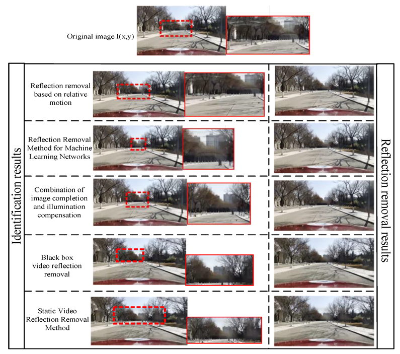
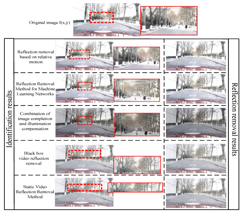
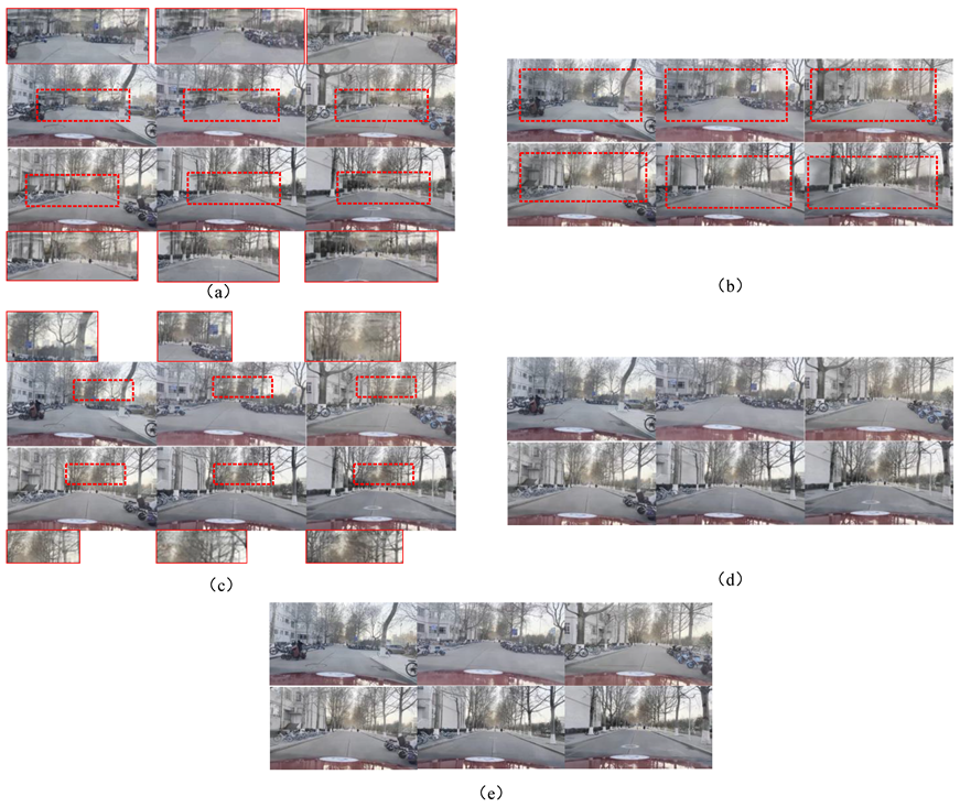
4.2. Comparison with Advanced Technology

To be fair, we only compared the reflection region removal method based on relative motion [22], the reflection region removal method based on machine learning networks [4], and the reflection region removal method proposed in this paper that combines image completion and lighting compensation. Please note that our method is not designed to achieve optimal reaction time but to emphasize the advantages of our simple structure and the adaptability of the method in changing environments.
Discriminant analysis. Our method was used to validate the adaptability of each method in two different environments (light intensity σ 1 = 50 l x , σ 2 = 150 l x ). We collected a real car video frame sequence for our experiment, which resulted in a dataset of 2318 reflection images. Our method, as shown in Table 1, has an average reduction of +1.34% in recognition and decision-making time compared to the other two methods, demonstrating its practical value. However, our method still lags behind machine learning networks in terms of the detection time for reflection regions.
Due to the similarity between the accuracy evaluation criteria of the reflection area removal method and the mechanism of obstacle recognition, this paper evaluates the advantages and disadvantages of reflection removal methods based on the interference of the reflection area on the normal recognition of obstacles during the obstacle recognition process and the traditional normalized product correlation (NCC) evaluation criteria for image matching. The calculation formulas for the accuracy evaluation index of the reflection area recognition are D T = a i a i + c i + d i and R T = a i + c i a i + c i + d i .
The data in Table 2 include the number of video frame images in which each method detects a reflection area in the same video, which can be divided into the number of images that can detect the reflection area and the number of images that cannot detect the reflection area ( c i ). By setting the reflection result threshold Q i , the number of samples that can recognize the reflection area and the number of pixels in the reflection area is greater than the threshold, which is denoted as a i ; the number of samples that have a reflection area and the number of pixels in the reflection area being less than the threshold is denoted as b i ; the number of samples that have a reflection area greater than the threshold, but the detection result has no reflection area is denoted as c i ; and the number of samples that have a reflection area less than the threshold, but the detection result has no reflection area is denoted as d i .
Adaptability comparison. Table 2 shows that we evaluated our algorithm by calculating the normalized cross correlation (NCC) of the ground truth decomposition we recovered. The NCCs of the reflection layer we separated were 0.89236, 0.86982, 0.91563, 0.90642, and 0.88959, while the NCCs of the background layer were 0.86624, 0.87431, 0.90875, 0.90433 and 0.89746, respectively. The RT, DT, and NCC of the reflection region removal method based on image completion and lighting compensation are higher than the other four methods. In this paper, it was observed that differences in lighting intensity in various driving environments can lead to false detections and missed detections. To address this issue, the proposed method automatically adjusts the image brightness and increases a layer gradient difference through lighting compensation. This leads to a reduction in the missed recognition rate and an improvement in the comprehensiveness of reflection region removal. Figure 8, Figure 9, Figure 10 and Figure 11 show the reflection removal effect under different lighting conditions.
From Figure 10 and Table 2, it can be seen that under lighting conditions, machine learning methods may result in incomplete video reflection removal due to training factors and sudden changes in the environment. The method based on relative motion cannot completely eliminate the reflection area under lighting conditions. The reflection removal methods based on black box videos and static videos have significant errors in selecting ROI regions due to lighting factors. This leads to a blurring of the reflection area and an increase in the false detection rate of obstacles. The method proposed in this paper is effective in removing video reflections. By reducing the weight of lighting brightness and angles, the effect of reflection removal is achieved. The results indicate that under lighting conditions, local reflection areas can be completely eliminated. It reduces the false detection rate of obstacles caused by radiation. Table 3 compares the more popular methods in recent years. It can be seen that the method proposed in this paper has the highest adaptability—that is, the best reflection removal effect—whether in the presence or absence of light.
According to Figure 11, it can be seen that the reflection removal effect of each method is relatively better under no light conditions than under light conditions. Due to local reflections, there is a phenomenon of incomplete reflection removal. The reflection removal method based on black box video and still video suppresses the shadow problem that occurs during reflection removal under lighting conditions. The method proposed in this paper can effectively remove local area reflections under weak illumination. Due to the weakening of lighting, the reflection area is not obvious, which has a small impact on vehicle obstacle detection. Experiments have shown that the method proposed in this paper can effectively remove reflections from car mounted videos with and without light, and the effect is good.

5. Conclusions

This paper proposes a reflective region removal method based on the combination of image complementation and illumination compensation, which uses illumination compensation to keep the brightness of the reflective region stable in real-time during the reflective region extraction, and eliminates the process of ellipse region fitting and the SIFT or ASIFT extraction of feature points via fast image region matching, combining the MSER-based fast image region matching method with the illumination compensation mechanism. The combination of the MSER-based fast image region matching method, illumination compensation mechanism, and image complementation-based reflective region removal method reduces the spatial and temporal complexity of the reflective region of the vehicle’s front windshield and improves the speed and accuracy of reflective region extraction. In the reflective region removal process, the following occur: re-extracting video frame image sequences, forming custom image sequences, performing illumination compensation for the reflective region mapping in each image, keeping the illumination intensity of the reflective region of the custom image sequence consistent, restoring the reflective region covered with the background layer by combining the non-reflective region of each image with the same reflective region, and removing the reflective region using image difference. The video image sequence containing the reflected region is finally removed with image difference, and the process clearly illustrates the feasibility of the detection method combining image complementation and illumination compensation. In order to solve the problem of the incomplete extraction of reflective regions caused by real-time luminance changes, this paper uses the combination of luminance adjustment and gamma correction in the process of light compensation to improve the contrast of the deep and shallow parts of the image by setting the gamma function, which improves the problem of the incomplete identification of reflective regions with luminance adjustment only.
The reflective region identification and removal process of the reflective region removal method are based on the combination of image complementation and illumination compensation and are illustrated through real-vehicle tests. The reflective region removal method based on image complementation, the reflective region removal method based on relative motion, and the proposed method are compared in a real vehicle test outdoors, and the test results are compared using DT, RT, and NCC as evaluation indexes. The results show that the method has high accuracy, and the reasons for the high accuracy are analyzed. The reflective area removal method based on image complementation, the reflective area removal method based on reflective area removal, and the reflective area removal speed of the method were compared; the results showed that the method has a faster processing speed, and the reasons for the faster processing speed were analyzed. However, the method is slow in decision making, which may lead to the problem of time delay in the reflected area. A future research direction will focus on the design of a reflection region removal decision system that can reduce time delays under the condition of complete reflection region removal.

Author Contributions

Conceptualization, J.N. and Y.X.; methodology, S.D.; software, Y.X., S.D.; validation, S.D., X.K. and S.S.; investigation, S.D.; resources, Y.X. and S.D.; data curation, Y.X., S.D.; writing—original draft preparation, S.D.; writing—review and editing, Y.X. and S.D.; supervision, Y.X., S.D. and J.N.; project administration, Y.X.; funding acquisition, Y.X. All authors have read and agreed to the published version of the manuscript.

Funding

This work was supported in part by the National Natural Science Foundation of China under Grant 51905320 and 52102465, the Natural Science Foundation of Shandong Province under Grant ZR2022MF230, Experiment technology upgrading project under Grant 2022003, and the Shandong provincial programme of introducing and cultivating talents of discipline to universities: research and innovation team of intelligent connected vehicle technology.

Institutional Review Board Statement

Not applicable.

Informed Consent Statement

Not applicable.

Data Availability Statement

Not applicable.

Conflicts of Interest

The authors declare that the research was conducted in the absence of any commercial or financial relationships that could be construed as potential conflicts of interest.

References

  1. Chen, J. Single Image Reflection Removal with Camera Calibration. Master’s Thesis, Nanyang Technological University, Singapore, 2021; pp. 1–62. [Google Scholar]
  2. Levin, A.; Weiss, Y. User assisted separation of reflections from a single image using a sparsity prior. IEEE Trans. Pattern Anal. Mach. Intell. 2007, 29, 1647–1654. [Google Scholar] [CrossRef] [PubMed]
  3. Li, Y.; Brown, M.S. Single image layer separation using relative smoothness. In Proceedings of the IEEE Conference on Computer Vision and Pattern Recognition, Columbus, OH, USA, 23–28 June 2014; pp. 2752–2759. [Google Scholar]
  4. Zhang, Y.N.; Shen, L.; Li, Q. Content and Gradient Model-driven Deep Network for Single Image Reflection Removal. In Proceedings of the 30th ACM International Conference on Multimedia, Lisbon, Portugal, 10–14 October 2021; pp. 6802–6812. [Google Scholar]
  5. Zheng, Q.; Qiao, X.; Cao, Y.; Guo, S.; Zhang, L.; Lau, R.W. Distilling Reflection Dynamics for Single-Image Reflection Removal. In Proceedings of the IEEE/CVF International Conference on Computer Vision, Venice, Italy, 11–17 October 2021; pp. 1886–1894. [Google Scholar]
  6. Han, B.J.; Sim, J.Y. Single image reflection removal using non-linearly synthesized glass images and semantic context. IEEE Access. 2019, 7, 170796–170806. [Google Scholar] [CrossRef]
  7. Li, T.; Lun, D.P.K. Single-image reflection removal via a two-stage background recovery process. IEEE Signal Process. Lett. 2019, 26, 1237–1241. [Google Scholar] [CrossRef]
  8. Chi, Z.; Wu, X.; Shu, X.; Gu, J. Single image reflection removal using deep encoder-decoder network. arXiv 2018, arXiv:1802.00094. [Google Scholar]
  9. Li, Y.; Liu, M.; Yi, Y.; Li, Q.; Ren, D.; Zuo, W. Two-Stage Single Image Reflection Removal with Reflection-Aware Guidance. arXiv 2020, arXiv:2012.00945. [Google Scholar] [CrossRef]
  10. Chang, Y.C.; Lu, C.N.; Cheng, C.C.; Chiu, W.C. Single image reflection removal with edge guidance, reflection classifier, and recurrent decomposition. In Proceedings of the IEEE/CVF Winter Conference on Applications of Computer Vision, Virtual Conference, 5–9 January 2021; pp. 2033–2042. [Google Scholar]
  11. Fan, Q.; Yang, J.; Hua, G.; Chen, B.; Wipf, D. A Generic Deep Architecture for Single Image Reflection Removal and Image Smoothing. In Proceedings of the IEEE International Conference on Computer Vision (ICCV), Venice, Italy, 22–29 October 2017. [Google Scholar]
  12. Yang, J.; Gong, D.; Liu, L.; Shi, Q. Seeing deeply and bidirectionally: A deep learning approach for single image reflection removal. In Proceedings of the European Conference on Computer Vision, Munich, Germany, 8–14 September 2018; pp. 654–669. [Google Scholar]
  13. Li, C.; Yang, Y.; He, K.; Lin, S.; Hopcroft, J.E. Single image reflection removal through cascaded refinement. In Proceedings of the IEEE/CVF Conference on Computer Vision and Pattern Recognition, Long Beach, CA, USA, 15–20 June 2019; pp. 3565–3574. [Google Scholar]
  14. Wen, Q.; Tan, Y.; Qin, J.; Liu, W.; Han, G.; He, S. Single image reflection removal beyond linearity. In Proceedings of the IEEE/CVF Conference on Computer Vision and Pattern Recognition, Long Beach, CA, USA, 15–20 June 2019; pp. 3771–3779. [Google Scholar]
  15. Ren, W. Low-Light Image Enhancement via a Deep Hybrid Network. IEEE Trans. Image Process. 2019, 28, 4364–4375. [Google Scholar] [CrossRef] [PubMed]
  16. Aizu, T.; Matsuoka, R. Reflection Removal Using Multiple Polarized Images with Different Exposure Times. In Proceedings of the 30th European Signal Processing Conference (EUSIPCO), Belgrade, Serbia, 29 August–2 September 2022; pp. 498–502. [Google Scholar]
  17. Szeliski, R.; Avidan, S.; Anandan, P. Layer extraction from multiple images containing reflections and transparency. In Proceedings of the IEEE Conference on Computer Vision and Pattern Recognition—CVPR 2000, Hilton Head, SC, USA, 15 June 2000; Volume 1, pp. 246–253. [Google Scholar]
  18. Li, Y.; Brown, M.S. Exploiting reflection change for automatic reflection removal. In Proceedings of the IEEE International Conference on Computer Vision (ICCV), Santiago, Chile, 7–13 December 2015; pp. 2432–2439. [Google Scholar]
  19. Sun, C.; Liu, S.; Yang, T.; Zeng, B.; Wang, Z.; Liu, G. Automatic reflection removal using gradient intensity and motion cues. In Proceedings of the 24th ACM International Conference on Multimedia, Amsterdam, The Netherlands, 15–19 October 2016; pp. 466–470. [Google Scholar]
  20. Bonekamp, J. Multi-Image Optimization Based Specular Reflection Removal from Non-Dielectric Surfaces. Master’s Thesis, Delft University of Technology, Delft, The Netherlands, 2021. [Google Scholar]
  21. Wan, R.; Shi, B.; Duan, L.Y.; Tan, A.H. Crrn: Multi-scale guided concurrent reflection removal network. In Proceedings of the IEEE Conference on Computer Vision and Pattern Recognition, Salt Lake City, UT, USA, 19–21 June 2018; pp. 4777–4785. [Google Scholar]
  22. Xue, T.; Rubinstein, M.; Liu, C.; Freeman, W.T. A computational approach for obstruction-free photography. ACM Trans. Graph 2015, 34, 1–11. [Google Scholar]
  23. Cheong, J.Y.; Simon, C.; Kim, C.-S.; Park, I.K. Reflection removal under fast forward camera motion. IEEE Trans. 2017, 26, 6061–6073. [Google Scholar] [CrossRef] [PubMed]
  24. Iwata, S.; Ogata, K.; Sakaino, S.; Tsuji, T. Specular reflection removal with high-speed camera for video imaging. In Proceedings of the IECON 2015—41st Annual Conference of the IEEE Industrial Electronics Society, Yokohama, Japan, 9–12 November 2015; pp. 001735–001740. [Google Scholar]
  25. Alayrac, J.B.; Carreira, J.; Zisserman, A. The visual centrifuge: Model-free layered video representations. In Proceedings of the IEEE/CVF Conference on Computer Vision and Pattern Recognition, Long Beach, CA, USA, 15–20 June 2019; pp. 2457–2466. [Google Scholar]
  26. Li, T.; Lun, D.P.K. A novel reflection removal algorithm using the light field camera. In Proceedings of the IEEE International Symposium on Circuits and Systems (ISCAS), Florence, Italy, 27–30 May 2018; pp. 1–5. [Google Scholar]
  27. Lei, C.; Chen, Q. Robust reflection removal with reflection-free flash-only cues. In Proceedings of the IEEE/CVF Conference on Computer Vision and Pattern Recognition, Nashville, TN, USA, 20–25 June 2021; pp. 14811–14820. [Google Scholar]
  28. Li, T.; Lun, D.P.K.; Chan, Y.H. Robust reflection removal based on light field imaging. IEEE Trans. Image Process. 2018, 28, 1798–1812. [Google Scholar] [CrossRef] [PubMed]
  29. Punnappurath, A.; Brown, M.S. Reflection removal using a dual-pixel sensor. In Proceedings of the IEEE/CVF Conference on Computer Vision and Pattern Recognition, Nashville, TN, USA, 5–9 June 2019; pp. 1556–1565. [Google Scholar]
  30. Hong, Y.; Lyu, Y.; Li, S.; Shi, B. Near-infrared image guided reflection removal. In Proceedings of the IEEE International Conference on Multimedia and Expo (ICME), London, UK, 6–10 July 2020; pp. 1–6. [Google Scholar]
  31. Sheridan, K.; Puranik, T.G.; Mangortey, E.; Pinon, O.J.; Kirby, M.; Mavris, D. An Application of DBSCAN Clustering for Flight Anomaly Detection during the Approach Phase. In Proceedings of the AIAA SciTech Forum, Orlando, FL, USA, 6–10 January 2020; p. 1851. [Google Scholar]
  32. Jiang, G.; Xu, Y.; Gong, X.; Gao, S.; Sang, X.; Zhu, R.; Wang, L.; Wang, Y.J.J.o.R. An Obstacle Detection and Distance Measurement Method for Sloped Roads Based on VIDAR. J. Robot. 2022, 2022, 5264347. [Google Scholar] [CrossRef]
  33. Nandoriya, A.; Elgharib, M.; Kim, C.; Hefeeda, M.; Matusik, W. Video reflection removal through spatio-temporal optimization. In Proceedings of the IEEE International Conference on Computer Vision, Venice, Italy, 22–29 October 2017; pp. 2411–2419. [Google Scholar]
  34. Simon, C.; Kyu Park, I. Reflection removal for in-vehicle black box videos. In Proceedings of the IEEE Conference on Computer Vision and Pattern Recognition, Boston, MA, USA, 7–12 June 2015; pp. 4231–4239. [Google Scholar]
Figure 1. Physical (left) and mathematical (middle) image formation models of the image reflection removal method and the actual experimental presentation scenario (right). Types I and II ignore the refraction effect of thicker glass, while type III exists with thicker glass, which reflects and refracts light from the glass front object to different locations and exhibits different intensities, respectively, leading to the superimposed image phenomenon of the mirror front object in the reflective layer.
Applsci 13 10913 g001
Figure 2. An overview of our method. The blue module is used for video framing operations, selecting images with reflective areas, calculating the number of images used in the image sequence (represented by the green module), and then adding lighting compensation for image completion (represented by the orange module). Reflection removal is achieved through the difference between the image and the reflection layer (represented by the pink module). Finally, image collection and video restoration (represented by the purple module) are carried out.
Applsci 13 10913 g002
Figure 3. A flowchart of the reflective region removal method based on the combination of image complementation and illumination compensation.
Applsci 13 10913 g003
Figure 4. A diagram of the unchanged reflection area.
Applsci 13 10913 g004
Figure 5. The results of an image complementation-based reflective region removal method.
Applsci 13 10913 g005
Figure 6. Experimental equipment.
Applsci 13 10913 g006
Figure 7. Partial dataset.
Applsci 13 10913 g007aApplsci 13 10913 g007b
Figure 8. A comparison of five reflection removal methods under a normal driving environment.
Applsci 13 10913 g008
Figure 9. A comparison of five reflection removal methods under normal lighting conditions.
Applsci 13 10913 g009
Figure 10. The results of five reflection removal methods under light conditions where (a) is the removal result of the reflection region removal method based on relative motion, (b) is the removal result of the black box video reflection removal, (c) is the removal result of the reflection region removal method based on image completion, (d) is the removal result based on the Static Video method, and (e) is the removal result of the reflection region removal method based on the combination of image completion and light compensation.
Applsci 13 10913 g010
Figure 11. The plot of the results of five reflection removal methods in a normal driving environment where (a) is the removal result of the reflection region removal method based on relative motion, (b) is the removal result of the black box video reflection removal, (c) is the removal result of the reflection region removal method based on image completion, (d) is the removal result based on the Static Video method, and (e) is the removal result of the reflection region removal method based on the combination of image completion and light compensation.
Applsci 13 10913 g011
Table 1. A comparison of reflection area recognition and detection time.
MethodDetection Time/sIdentification Time/s
Reflection removal based on relative motion compensation2.4983.246
Reflection Removal Method for Machine Learning Networks2.4522.783
Combination of image completion and illumination2.6322.674
Static Video Reflection Removal Method [33]2.7442.863
Black box video reflection removal [34]2.5312.700
Table 2. A Comparison Table of the Data Results of Five Methods for Removing Reflection Regions.
Judgment BasisBlack Box Video Reflection RemovalStatic Video Reflection Removal MethodCombination of Image Completion and Illumination CompensationReflection Removal Method for Machine Learning NetworksReflection Removal based on Relative Motion
Reflection areaHaveNoneHaveNoneHaveNoneHaveNoneHaveNone
2126192
( c i )
2133185
( c i )
225464
( c i )
2218100
( c i )
2201117
( c i )
Whether the number of pixels exceeds the threshold Q i Yes2036
( a i )
892048
( a i )
782208
( a i )
232173
( a i )
362123
( a i )
49
No90
( b i )
103
( d i )
85
( b i )
107
( d i )
46
( b i )
41
( d i )
54
( b i )
55
( d i )
64
( b i )
82
( d i )
Check the accuracyDT0.9170.9200.9720.9330.914
RT0.9560.9540.9820.9760.965
NCCReflector0.892360.869820.915630.906420.88959
Background layer0.866240.874310.908750.904330.89746
Table 3. A comparison of reflection removal methods with and without illumination (NCC).
SequenceIlluminatedNo Light
Method ReflectorBackground LayerReflectorBackground Layer
Camera calibration removes single image reflections [1]0.898730.901650.887460.89647
Deep single image reflection removal driven by content and a gradient model [4]0.876520.865280.867730.85631
A combination of image completion and illumination0.915630.908750.908970.89745
Static Video Reflection Removal Method [33]0.869820.874310.862320.86968
Black box video reflection removal [34]0.892360.866240.887460.86364
Removing reflections from multiple polarized images with different exposure times [16]0.903650.903690.895410.89796
An edge-guided removal of single image reflections [10]0.896770.906230.889650.88943
The removal of specular reflection from non-dielectric surfaces based on multi-image optimization [20]0.889720.897480.876440.89656
Disclaimer/Publisher’s Note: The statements, opinions and data contained in all publications are solely those of the individual author(s) and contributor(s) and not of MDPI and/or the editor(s). MDPI and/or the editor(s) disclaim responsibility for any injury to people or property resulting from any ideas, methods, instructions or products referred to in the content.

