Abstract
The positional accuracy and orientation accuracy of industrial robots are crucial technical indicators for determining their applicability in industrial scenarios. However, the majority of current calibration methods for industrial robots only consider positional errors, neglecting the significance of orientation accuracy. This paper presents a more accurate error model and parameter calibration method for industrial robots based on six degrees-of-freedom position and orientation to identify the actual structural parameters. Firstly, based on the modified Denavit–Hartenberg parameters, the transformation errors of the tool coordinate system and measurement coordinate frame were introduced to establish a geometric parameter error model with positional and orientation accuracy as the optimization objectives. Secondly, to address the drawback of falling into local optima when identifying geometric parameters simultaneously, a geometric parameter cross-identification method based on the Levenberg–Marquardt algorithm is proposed. Lastly, the linear relationship between the parameters was analyzed, and a scheme for not calibrating some geometric parameters under specific conditions was given. Simulation results demonstrated that, under the premise of existing transformation errors, the proposed geometric parameter error model can accurately identify the actual structural parameters of industrial robots. After calibration, the positional error at the robot’s flange end decreased from 1.9536 mm to 0.0122 mm, and the orientation error decreased from 1.46 × 10⁻² rad to 1.31 × 10⁻⁴ rad. Furthermore, compared to identifying the geometric parameters simultaneously, the proposed cross-identification method has a wider convergence range.
1. Introduction
Industrial robots are multi-mechanical-arm or multi-degree-of-freedom robots designed for industrial applications that can replace humans in performing simple and repetitive tasks in harsh environments [1,2,3]. Over time, the repeatability of industrial robots can be affected by changes in the precision of the joint gear system and the resolution of the encoder. The accuracy of robots can also be influenced by geometric factors such as deviations in link parameters and coordinate frame definitions, as well as non-geometric factors like temperature and deformations. These factors can lead to deviations in the pose of the end effector of industrial robots, which can impact the quality of associated products. On one hand, industrial robots generally have high repeatability, often reaching the level of 0.1 mm, but their absolute positioning accuracy is usually in the millimeter range. On the other hand, the accuracy of industrial robots gradually deteriorates with increasing operating time, and the rate of deterioration determines their lifecycle. As industrial robots find broader applications, meeting the repeatability requirement alone is no longer sufficient, and the low absolute positioning accuracy becomes a bottleneck for further development. Therefore, improving absolute positioning accuracy has become an urgent problem for industrial robot manufacturers.
The calibration of Industrial robots [4,5] typically involves four steps: kinematic modeling, pose measurement, parameter identification, and error compensation. Kinematic modeling serves as the mathematical foundation in the field of industrial robot calibration. In the 1950s, Denavit and Hartenberg proposed the Denavit–Hartenberg model (DH) [6], which expresses the spatial coordinate transformation between adjacent joints by defining four parameters: link length , link offset , link twist , and joint angle . The DH model has clear physical significance, is convenient to use, and satisfies the principle of minimization [7]. However, a wealth of research studies have demonstrated that the DH model fails to meet the continuity requirement when the axes of adjacent joints are parallel or nearly parallel. To address this singularity issue while maintaining the model’s parameter minimization principle, a modified Denavit–Hartenberg model (MDH) [8,9] was proposed by adding a parameter for rotation around the y-axis in parallel or nearly parallel singular joint coordinate frames. In [10], Stone et al. redefined the rules for establishing the link coordinate frame and proposed the S model. In the S model, each link is described by six parameters, including three translation parameters and three rotation parameters, but it does not satisfy the principle of minimization and contains redundant parameters [11]. Zhuang et al. proposed the complete and parametrically continuous model (CPC) based on the idea that a kinematic model for robot calibration needs to satisfy both “completeness” and “parameter continuity” [12]. In [13,14], the kinematic model of industrial robots was described as a product of a series of exponential matrices, known as the product of the exponentials (POE) model, which does not have parameters that mutate in terms of phenomena. To address the issue of model discontinuity commonly encountered in the traditional DH model, Zhang et al. proposed a local product of the exponential model [15]. To reduce the difficulty of kinematic modeling, many researchers have considered using neural networks to depict the relationship between the end effector error and the joint angles of industrial robots [16,17]. Maghami et al. proposed a two-step calibration method for a master-slave collaborative robot system based on artificial neural networks (ANNs), using joint angles and output pose errors as the training data [18]. Ma et al. employed an incremental extreme learning machine (IELM) to predict the positioning error of an industrial robot and improve its positioning accuracy [19]. To improve the tracking accuracy of joint angles, Tan et al. proposed a robot-tracking error prediction and compensation method based on time-convolutional networks (TCN) [20]. In [21], Bo et al. used a genetic particle swarm optimization algorithm to optimize a neural network for predicting the positioning error of an industrial robot, thus improving the positioning accuracy of a KUKA robot.
Among all the mathematical models mentioned above, the MDH model is the most widely used in the field of industrial robot calibration due to its features of parameter completeness, minimization, continuity, and clear physical significance. Guo et al. established a geometric parameter error model for SCARA robots based on the MDH model and identified the corresponding structural parameters [22]. Song et al. derived geometric and deformation errors based on the MDH model, combined them into a complete model, and proposed a step-by-step compensation method [23]. In [24], a kinematic error model for FANUC robots was established based on the MDH model, and the Levenberg-Marquardt algorithm (LM) and differential evolution algorithm (DE) were used to identify and optimize the related parameters. Chen et al. analyzed the joint motion of KUKA robots according to the MDH model and proposed a kinematic calibration method based on an improved beetle swarm optimization algorithm [25]. Selami et al. presented a 3DPP measurement device and kinematic parameter identification method based on the MDH model for the calibration of 6 degrees-of-freedom (DOF) industrial manipulators [26].
However, the majority of the aforementioned industrial robot calibration methods primarily focus on positional errors, neglecting the importance of orientation accuracy. Moreover, when the calibration of the tool coordinate frame and measurement coordinate frame is not sufficiently accurate (i.e., when there is a significant transformation error), the identification results based on the MDH error model often differ greatly from the actual structural parameters of the industrial robot [27]. Additionally, industrial robot parameter identification is susceptible to falling into local optima due to the effects of transformation errors in the tool coordinate frame and measurement coordinate frame and other random noise. To address these issues, this paper presents a more accurate error model and parameter calibration method for industrial robots based on 6-DOF position and orientation to identify the actual structural parameters. The main contributions are as follows: (1) based on the modified Denavit–Hartenberg parameters, the transformation errors of tool coordinate system and measurement coordinate frame were introduced to establish a geometric parameter error model, which uses positional and orientation accuracy as optimization objectives; (2) to overcome the problem of easily falling into local optima when identifying geometric parameters simultaneously, a geometric parameter cross-identification method based on the Levenberg-Marquardt algorithm is proposed; (3) the linear relationships between the parameters of the proposed geometric error model are investigated, and a solution for not calibrating some geometric parameters under specific conditions is provided.
2. Industrial Robot Kinematic Analysis
Industrial robot calibration is the process of identifying the structural parameters of the robot based on its end-effector error. It involves complex theoretical knowledge. In this section, the definitions of coordinate frames involved in the industrial robot calibration process are presented. Additionally, the practical significance of DH parameters and the MDH model are explained. Finally, the forward kinematics equation of industrial robots, the transformation matrix representing the tool coordinate frame relative to the flange coordinate frame, and the transformation matrix representing the base coordinate frame relative to the measurement coordinate frame are provided.
2.1. Definitions of Coordinate Frames
The industrial robot parameter identification system involves the following coordinate frames: measurement coordinate frame (MCF), base coordinate frame (BCF), joint coordinate frame (JCF), flange coordinate frame (FCF), and tool coordinate frame (TCF). The definitions of the above coordinate frames are shown in Figure 1. The BCF is established on the robot’s base. The transformation from the BCF to the MCF is defined as , which needs to be calibrated before performing parameter identification. The TCF is fixed at the robot’s flange, and its origin is at the center of the tool. The transformation from the TCF to the FCF is defined as , which also needs to be calibrated before parameter identification. The transformation from the FCF to the BCF is defined as and is obtained by multiplying the transformation of adjacent joint coordinate frames in the order. The transformation from the TCF to the MCF is defined as , which represents the position of the TCF relative to the MCF. The reference coordinate frame selected in this article is the MCF.
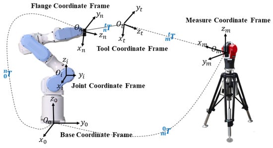
Figure 1.
The definitions of coordinate frames.
2.2. Kinematic Model
The prerequisite for the calibration work of industrial robots is to establish an appropriate kinematic model to describe the relationship between the end pose of the industrial robot and its structural parameters, such as link lengths and joint angles. In 1955, Denavit and Hartenberg proposed a method based on matrix transformations to describe the motion of link mechanisms, as shown in Figure 2. Here, represents the link length, represents the link offset, represents the joint angle, and represents the joint twist.
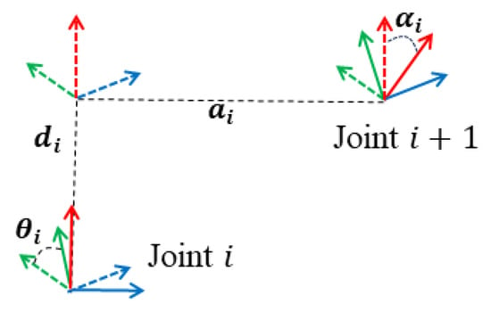
Figure 2.
DH parameters (where, red arrow is z-axis, green arrow is y-axis and blue arrow is x-axis).
However, when the axes of two adjacent joints are parallel or nearly parallel, a small deviation, in the end, the pose of the industrial robot will cause the structural parameters related to the parallel joints to change abruptly (i.e., the theoretical DH model has singularities). Therefore, this paper selected the MDH model proposed in [8] to establish the error model of industrial robots. When the axes of adjacent joints are parallel, an additional rotation angle around the y-axis is added to the theoretical DH model. Then, the transformation matrix between adjacent joint coordinate frames is defined as follows:
where denotes the sine function, and denotes the cosine function.
Based on Equation (1), for an n-DOF industrial robot, its forward kinematic equation can be expressed as follows:
During the installation process, it is typically required that the TCF and the FCF only have a translational relationship. However, due to limitations in manual operations, there may still be certain rotational relationships between the TCF and the FCF. Similarly, there are translation and rotation relationships between the BCF and the MCF. The transformation matrix that includes both rotation and translation is generally represented as follows:
where is the translation transformation, is the yaw angle around the z-axis, is the pitch angle around the y-axis, and is the roll angle around the x-axis.
If is set to and is set to , then the pose of the TCF relative to MCF is as follows:
3. Error Model and Cross-Identification Algorithm
There are several factors that contribute to the errors of industrial robot end effectors, including assembly and installation errors during the robot manufacturing process, wear and tear errors over extended use, deformations due to loads, and more. These factors collectively result in deviations in the pose of the robot end effector. In fact, the above errors can be categorized into three types: geometric errors, non-geometric errors, and random errors. Among these, geometric errors primarily refer to deviations in link parameters caused by inaccurate manufacturing and installation. Non-geometric errors mainly denote elastic deformation deviations due to temperature and loads, while random errors are induced by electromagnetic interference and collisions. Motta et al. have indicated that approximately 95% of errors are caused by geometric parameter deviations [28]. Therefore, this paper focused on compensating for industrial robot end effector errors caused by geometric parameter deviations. This section first establishes an industrial robot geometric parameter error model (TM-MDH) based on modified Denavit–Hartenberg parameters and the transformation errors of the tool coordinate frame and measurement coordinate frame. Secondly, to address the disadvantage of easily falling into local optimization when identifying geometric parameters simultaneously, a geometric parameter cross-identification method (C-LM) based on the Levenberg–Marquardt algorithm is proposed.
3.1. Geometric Parameter Error Model
Differential motion is commonly used to describe the relationship between two small variables corresponding to joint space and the end effectors of industrial robots. Two forms of differential motion are translation transformation and rotation transformation. According to [29], the representation of differential motion is as follows:
where represents differential rotation, represents differential translation, and represents differential transformation matrix.
3.1.1. Differential Transformation Matrix
Let the parameter deviations of joint be . Then, the errors between the actual and nominal transformation matrix of adjacent joints can be approximated as a linear combination of the link parameter deviations:
Since the nominal is equal to 0, the partial derivative of Equation (1) with respect to is as follows:
where
Similarly, taking the derivative of Equation (1) with respect to , we can obtain , as shown in Table 1. Thus, Equation (6) can be rewritten as
where is the differential transformation matrix between adjacent joint coordinate frames.

Table 1.
The values of .
When there are deviations in the link parameters, ignoring the higher-order terms, the pose of the FCF relative to the BCF can be expressed as follows:
Thus, the differential transformation matrix from the TCF to the BCF is as follows:
where .
3.1.2. Differential Transformation Matrices and
The pose of the BCF relative to the MCF can be divided into translation and rotation . Its matrix form is shown in Equation (3). When its calibration is not accurate enough, the error between its actual and nominal value is as follows:
where represents the translation and orientation errors of the BCF relative to the MCF.
Taking the derivative of Equation (3) with respect to , we can obtain the following:
where
Similarly, by taking the derivative of Equation (3) with respect to , we can obtain , as shown in Table 2. Thus, Equation (12) can be rewritten as follows:

Table 2.
The values of .
Therefore, the differential transformation matrix from the BCF to the MCF is as follows:
Similarly, the differential transformation matrix from the TCF to the FCF is similar to and is given by
where represents the translation and orientation errors of the TCF relative to the FCF.
3.1.3. Differential Transformation Matrix
For an n-DOF industrial robot, when there are deviations in the link parameters and transformation errors between the BCF and the MCF, as well as between the TCF and the FCF, the pose of the TCF in the MCF can be expressed as follows:
According to Equations (11), (16) and (17), the differential transformation matrix of the TCF relative to the MCF is as follows:
where , , and , which are the parameters to be identified in the calibration process. and are as follows:
3.1.4. TM-MDH Error Model
In Equation (19), and follow the form of Equation (5). Similarly, also follows the same form, specifically:
where is equal to ,which represents the differential translation of the TCF relative to the MCF. is equal to , which represents the differential rotation of the TCF relative to the MCF.
Set the errors of the link parameters as , , , , and Based on Equation (19), the geometric parameters error model (TM-MDH) can be established as follows:
where . is the column vector composed of the elements of the corresponding matrix at (1, 4), (2, 4), and (3, 4). is the column vector composed of the elements of the corresponding matrix at (1, 2), (1, 3), and (2, 3). and are 3 × n matrices. , , , and are 3 × 6 matrices.
3.2. Cross-Identification Method Based on LM Algorithm
The classical industrial robot parameter identification algorithms include the least square algorithm (LS) [30], the extended Kalman filter (EKF) [31], and the Levenberg-Marquardt algorithm (LM) [32]. Among them, the LM algorithm combines the steepest descent method and the Newton method, and can quickly complete the identification task. It has excellent performance in terms of local convergence and anti-disturbance and is most commonly used.
3.2.1. LM Algorithm
Equation (23) establishes the linear transformation relationship between the pose error of the TCF in the MCF and the geometric parameter error. Obviously, as long as there are enough sets of tool end pose data, an overdetermined linear equation system can be constructed to represent the tool end pose error and geometric parameter error, and then the calibration of robot parameters can be achieved. Assuming that there are sets of tool end poses, according to Formula (23), we have the following:
Equation (25) can be simplified as follows:
Thus, the industrial robot geometric parameter identification problem is transformed into a linear equation system solving the problem. The LM algorithm can solve the above problem, and its iteration steps at the k-th iteration are as follows:
Step 1: Calculate the Jacobian matrix based on the industrial robot structural parameters and the transformation parameters .
Step 2: Calculate the geometric parameter error vector according to the following equation:
where is the damping coefficient, which can be calculated as follows:
Step 3: Update the geometric parameters based on .
3.2.2. C-LM Algorithm
In Equation (23), since the first column of the is zero, the joint angle cannot be identified when the optimization objective is solely the differential translation . Similarly, due to and being zero, and the first three columns of and also being zero, the parameters such as link length , link offset , translation between the BCF and the MCF, and translation between the TCF and the FCF cannot be identified when the optimization objective is solely the differential rotation . Furthermore, when attempting to simultaneously identify all geometric parameters using Equation (25) and the LM algorithm, the results are prone to becoming trapped in local optima.
To address the aforementioned issues, this paper proposes a geometric parameter cross-identification method based on the LM algorithm. The specific steps are as follows:
Step 1: Considering only the differential rotation as the optimization objective, use the LM algorithm to solve the pose part of the linear Equation (25). This step aims to identify the nonlinear parameters related to angles, which include , , , , and .
Step 2: Using the identified angular parameters from the previous step as the initial values, with the position error and differential rotation as the optimization targets, identify all linear and nonlinear parameters, where the linear parameters are , , , and . Note that the position error and the differential translation differ by a rotation matrix .
Step 3: Repeat the above two steps until the iteration termination condition is met.
The proposed C-LM algorithm identifies the nonlinear parameters related to the angles according to the differential rotation , and then uses it as the initial value to identify all the parameters to be sought. This solves the local optimal problem caused by the mutual interference of linear and nonlinear parameters when identifying geometric parameters simultaneously. Therefore, compared to the strategy of simultaneously identifying all parameters, the proposed C-LM algorithm is more likely to escape local minima, has a wider convergence range, and achieves higher identification accuracy. The flowchart of the geometric parameter cross-identification algorithm based on the LM algorithm is shown in Figure 3.
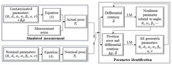
Figure 3.
Flowchart of the C-LM algorithm.
4. Simulation Analysis
To validate the effectiveness and correctness of the proposed TM-MDH error model and C-LM identification algorithm, numerical simulations were conducted using MATLAB R2016A software in this section. First, the source of the industrial robot tool end pose data in the simulation experiment is introduced. Secondly, according to the TM-MDH model proposed in Section 3.1 and the C-LM algorithm proposed in Section 3.2, all geometric parameters are identified, and their linear relationship is analyzed by observing the difference between them and the actual structural parameters of the industrial robot, and then a scheme for not identifying some geometric parameters under specific conditions is given. Lastly, the convergence of the proposed C-LM algorithm is analyzed, and measurement noise is introduced to evaluate the actual compensation effect of the TM-MDH model on pose accuracy.
4.1. Data Generation
In the simulation experiments, the nominal structural parameters are based on the BRTIRUS0707A robot, as shown in Table 3. The schematic diagram of the joint coordinate frames for the robot is shown in Figure 4. The structural parameter deviations for the BRTIRUS0707A robot are given in Table 4. The nominal transformation matrix between the BCF and the MCF, as well as the nominal transformation matrix between the TCF and the FCF, are set to the identity matrix , with deviations shown in Table 5.

Table 3.
Nominal structural parameters of the BRTIRUS0707A robot.
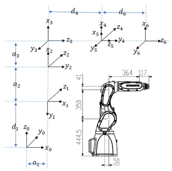
Figure 4.
Schematic diagram of the joint coordinate frames of the BRTIRUS0707A robot.

Table 4.
Preset deviations .

Table 5.
Preset deviations .
The cross-identification process for the geometric parameters of the industrial robot is shown in Figure 3. Since the industrial robot has 6 degrees of freedom, it is necessary to identify 25 structural parameters , 12 transformation parameters , giving a total of 37 geometric parameters. Each set of poses can construct six equations, so at least seven sets of nominal and actual poses of the TCF are required. In fact, the more sets of poses provided, the higher the identification accuracy of the geometric parameter deviation and the compensation accuracy of the end pose. In this paper, 100 sets of poses were randomly selected within the working space of the industrial robot.
4.2. Linear Relationship Analysis
Based on Table 3, Table 4 and Table 5, 100 sets of nominal poses and actual poses of the industrial robot were generated. Here, the actual poses do not include noise and are obtained solely from contaminated geometric parameters and forward kinematic equations. Assuming the C-LM algorithm is iterated 20 times, the cross-identification results of the TM-MDH model are shown in Table 6 and Table 7. It was found that 14 parameter identification results were anomalous. In this paper, the definition of parameter anomaly is as follows: if the relative error between the identified deviation of a parameter and its given theoretical value exceeds 2%, the identification result of that parameter is considered anomalous.

Table 6.
identification results without noise (the values in bold font indicate anomalies).

Table 7.
identification results without noise (the values in bold font indicate anomalies).
Analyzing the anomalous data of and in Table 6 and observing Figure 4, it can be concluded that as long as they satisfy Equation (29), their anomalies will not affect the actual pose of the industrial robot’s end effector. In other words, for the same pose, there exist an infinite number of sets of inverse solutions for and , indicating that the solution exhibits singularity.
Here, and are the identification results of the deviations for parameters and . and are the preset theoretical values for the deviations of parameters and .
Based on the above analysis, the preliminary results showed that there is a linear relationship between and , as their deviations sum up to a constant value equal to the sum of the preset deviations. Similarly, it can be inferred that there are linear relationships between and ; and ; and ; and ; and ; and and . To further validate these judgments, while keeping the other geometric parameters constant, we continuously adjusted the preset deviations of and , and observed the value of , as shown in Figure 5a. Upon observation, it was found that, for different preset deviations and , the value of consistently remained at zero. This demonstrates that there exists a linear relationship between the link offsets and for the BRTIRUS0707A robot. Similarly, Figure 5 can also be used to determine the linear relationships between and ; and ; and ; and ; and ; and and .
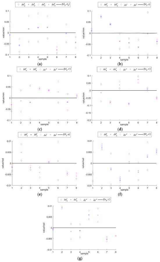
Figure 5.
Linear relationship experiment: (a) ; (b) ; (c) ; (d) ; (e) ; (f) ; (g) .
During the parameter identification process of the industrial robot, it was observed that there exists a linear relationship between and (i.e., can be expressed in terms of ). This indicates the presence of parameter redundancy, suggesting that the introduction of the transformation parameter would affect the identification of the actual structural parameter . To minimize the influence of introduced transformation parameters on the identification of actual structural parameters, in practical applications, if it can be ensured that the calibration of TCP and MCF is relatively accurate, the six transformation parameters can be excluded from identification.
4.3. Algorithm Verification and Compensation Result Analysis
This paper proposes a C-LM algorithm to solve the problem of easily falling into local optima when identifying geometric parameters simultaneously. To verify the sensitivity of the C-LM algorithm to the initial parameter values, convergence analysis was performed using different calibration algorithms on the TM-MDH model with different preset parameters ( and ). A deviation vector was added to the nominal parameters, where and varied from −3.1 rad to 3.1 rad with equal intervals. Under 63*63 sets of initial parameter conditions, different algorithms were used to validate the convergence of these cases.
Table 8 presents a comparison of the convergence indicators of the LM algorithm and the C-LM algorithm under different initial conditions. The criteria include run time and convergence ratio. From Table 8, it can be observed that both the LM algorithm and the C-LM algorithm had cases where the results did not converge, even after reaching the maximum number of iterations. However, the C-LM algorithm exhibited a higher global convergence ratio of 53.16%. The specific convergence conditions of the LM algorithm and C-LM algorithm are shown in Figure 6, which displays three-dimensional color maps of the final orientation error and position error of the cases with different initial values . It can be concluded that when the norm of the bias vector is relatively small, the algorithms tend to converge to the global optimum, as reflected by the large flat blue region in the middle of the three-dimensional color map. Clearly, the proposed C-LM algorithm has a broader global convergence range. That is to say, The C-LM algorithm is insensitive to the initial values of the parameters to be identified.

Table 8.
Comparison of convergence indicators for different algorithms under different initial values.
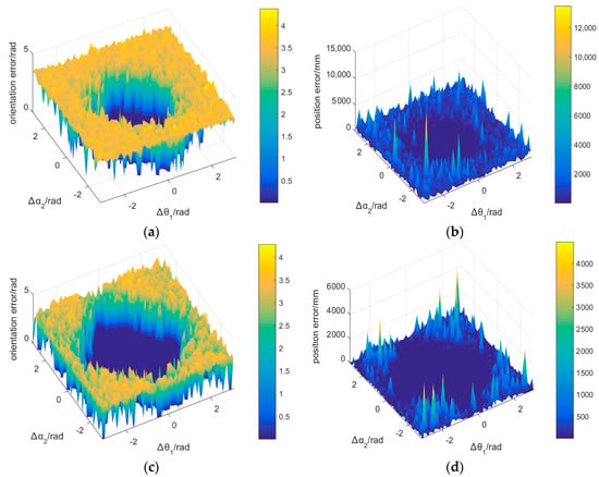
Figure 6.
The global convergence regions of different algorithms under various initial values; (a) Orientation error of LM; (b) Position error of the LM; (c) Orientation error of C-LM; (d) Position error of the C-LM.
Table 9 gives the identification results of the industrial robot’s structural parameters based on the C-LM algorithm, with and without introducing transformation parameters and . In this experiment, the true pose data of the TCP included Gaussian measurement noise with standard deviations of 0.02 mm for position noise and 0.002 rad for orientation noise. The position errors of the FCP relative to the BCF and the deviations along each axis are shown in Figure 7, while the orientation errors and the deviations around each axis are shown in Figure 8. The statistical results (mean, minimum, and maximum) are presented in Table 10 and Table 11.

Table 9.
Identification results of and under different error models with Gaussian noise.
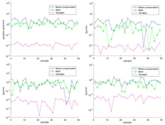
Figure 7.
The position errors and the deviations along each axis.
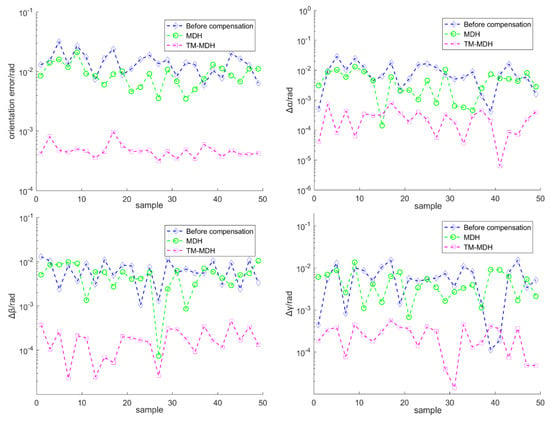
Figure 8.
The orientation errors and the deviations around each axis.

Table 10.
The position accuracy for different error models (mm).

Table 11.
The orientation accuracy for different error models (rad).
According to Table 9, it can be observed that when there were transformation errors, the structural parameters of industrial robots identified according to the traditional MDH model were significantly different from their actual values. In contrast, the proposed TM-MDH model, which is not affected by transformation errors, can effectively identify the actual structural parameters of the industrial robot. Based on Figure 7 and Figure 8, and Table 10 and Table 11, the following conclusions can be drawn: when transformation errors are present, the compensation effect of the TM-MDH model is excellent. After calibration using the C-LM algorithm, the position error of the FCF relative to the BCF decreased from 1.9536 mm to 0.0122 mm, and the orientation error decreased from 1.46 × 10⁻² rad to 1.31 × 10⁻⁴ rad.
5. Conclusions
This paper proposes a TM-MDH error model and a C-LM algorithm for identifying the actual structural parameters of industrial robots. The simulation results indicate that the proposed C-LM algorithm overcomes the drawback of easily falling into local optima when identifying geometric parameters simultaneously and exhibits a wider convergence range. Furthermore, the proposed TM-MDH model accurately describes the relationship between geometric errors and end-effector pose errors. After calibration by the C-LM algorithm, the positional error of the industrial robot’s flange end was reduced by 0.0122 mm from 1.9536 mm, and the orientation error was reduced by 1.31 × 10⁻⁴ rad from 1.46 × 10⁻² rad.
This study is an initial exploration of error models for calibrating industrial robots, considering only geometric parameters such as joint angles. Further research can incorporate motor gear ratios, coupling ratios, and link deformation parameters into the robot error model. It is worth noting that, besides geometric errors, there are other non-geometric errors and random errors. Therefore, establishing an end-effector accuracy compensation model for industrial robots using neural networks is an interesting research direction. Lastly, considering intelligent optimization algorithms such as differential evolution and genetic algorithms for identifying the structural parameters of industrial robots is also meaningful.
Author Contributions
Methodology, D.L. and Y.Q.; Software, D.L. and Y.Q.; Validation, D.L., Y.Q. and F.W.; Formal analysis, D.L., Y.Q. and F.W.; Investigation, D.L. and Y.L.; Resources, D.L. and Y.L.; Data curation, D.L. and Y.Q.; Writing—original draft, D.L., Y.Q., F.W. and Y.L.; Writing—review & editing, D.L.; Visualization, D.L. and Y.Q.; Supervision, Y.Q.; Project administration, D.L., Y.Q. and Y.L.; Funding acquisition, D.L. and Y.Q. All authors have read and agreed to the published version of the manuscript.
Funding
This work is supported by the Scientific and Technological Innovation Foundation of the Shunde Innovation School (Grant No. BK20BE019).
Institutional Review Board Statement
Not applicable.
Informed Consent Statement
Not applicable.
Data Availability Statement
Not applicable.
Acknowledgments
The authors are grateful to the editor and the anonymous referees for their constructive comments and recommendations, which have helped to improve this paper significantly. The authors would also like to express their sincere thanks to Hayati for the useful information regarding the MDH model.
Conflicts of Interest
The authors declare no conflict of interest.
Abbreviations
| DH | Denavit–Hartenberg Model |
| MDH | Modified Denavit–Hartenberg Model |
| CPC | Complete and Parametrically Continuous model |
| POE | Product of Exponentials Model |
| ANNs | Artificial Neural Networks |
| IELM | Incremental Extreme Learning Machine |
| TCN | Time Convolutional Networks |
| LM | Levenberg–Marquardt Algorithm |
| DE | Differential Evolution Algorithm |
| DOF | Degrees-of-Freedom |
| MCF | Measurement Coordinate Frame |
| BCF | Base Coordinate Frame |
| JCF | Joint Coordinate Frame |
| FCF | Flange Coordinate Frame, |
| TCF | Tool Coordinate Frame |
| C-LM | Cross-Identification Method |
| TM-MDH | An Error Model Based on Modified Denavit–Hartenberg Parameters and the Transformation Errors of Tool Coordinate Frame and Measurement Coordinate Frame |
References
- Wang, E.Z.; Lee, C.C.; Li, Y. Assessing the impact of industrial robots on manufacturing energy intensity in 38 countries. Energy Econ. 2022, 105, 105748. [Google Scholar] [CrossRef]
- Buerkle, A.; Eaton, W.; Al-Yacoub, A.; Zimmer, M.; Kinnell, P.; Henshaw, M.; Coombes, M.; Chen, W.-H.; Lohse, N. Towards industrial robots as a service (IRaaS): Flexibility, usability, safety and business models. Robot. Comput.-Integr. Manuf. 2023, 81, 102484. [Google Scholar] [CrossRef]
- Zhang, J.; Lou, Z.; Fan, K.-C. Accuracy improvement of a 3D passive laser tracker for the calibration of industrial robots. Robot. Comput.-Integr. Manuf. 2023, 81, 102487. [Google Scholar] [CrossRef]
- Balanji, H.M.; Turgut, A.E.; Tunc, L.T. A novel vision-based calibration framework for industrial robotic manipulators. Robot. Comput.-Integr. Manuf. 2022, 73, 102248. [Google Scholar] [CrossRef]
- Li, Z.; Li, S.; Wu, H. A New Variable Step-Size Levenberg-Marquardt Algorithm for Industrial Robot Calibration. In Proceedings of the 2022 IEEE International Conference on Networking, Sensing and Control (ICNSC), Shanghai, China, 15–18 December 2022; IEEE: Piscataway, NJ, USA, 2022; pp. 1–6. [Google Scholar]
- Denavit, J.; Hartenberg, R.S. A kinematic notation for lower-pair mechanisms based on matrices. J. Appl. Mech. 1955, 22, 215–221. [Google Scholar] [CrossRef]
- Zhang, T.; Song, Y.; Wu, H.; Wang, Q. A novel method to identify DH parameters of the rigid serial-link robot based on a geometry model. Ind. Robot. Int. J. Robot. Res. Appl. 2020, 48, 157–167. [Google Scholar] [CrossRef]
- Shi, B.; Wang, F.; Tian, Y.; Shi, R.; Zhao, X.; Zhang, D. Kinematic Calibration in Local Assembly Space of a Six-axis Industrial Robot for Precise Assembly. In Proceedings of the IEEE International Conference on Manipulation, Manufacturing and Measurement on the Nanoscale (3M-NANO), Tianjin, China, 8–12 August 2022; IEEE: Piscataway, NJ, USA, 2022; pp. 133–138. [Google Scholar]
- Wan, Z.; Zhou, C.; Lin, Z.; Yan, H.; Tang, W.; Wang, Z.; Wu, J. An Improved Design of the MultiCal On-Site Calibration Device for Industrial Robots. Sensors 2023, 23, 5717. [Google Scholar] [CrossRef] [PubMed]
- Stone, H.W.; Sanderson, A.C. Statistical performance evaluation of the S-model arm signature identification technique. In Proceedings of the 1988 IEEE International Conference on Robotics and Automation, Philadelphia, PA, USA, 24–29 April 1988; IEEE: Piscataway, NJ, USA, 1988; pp. 939–946. [Google Scholar]
- Peng, J.; Ding, Y.; Zhang, G.; Ding, H. An enhanced kinematic model for calibration of robotic machining systems with parallelogram mechanisms. Robot. Comput. Manuf. 2019, 59, 92–103. [Google Scholar] [CrossRef]
- Zhuang, H.; Wang, L.K.; Roth, Z.S. Error-model-based robot calibration using a modified CPC model. Robot. Comput.-Integr. Manuf. 1993, 10, 287–299. [Google Scholar] [CrossRef]
- Luo, R.; Gao, W.; Huang, Q. POE-based parameter calibration for industrial robots considering joint compliance. In Proceedings of the 5th International Conference on Robotics and Automation Sciences (ICRAS), Wuhan, China, 11–13 June 2021; IEEE: Piscataway, NJ, USA, 2021; pp. 15–22. [Google Scholar]
- Luo, R.; Gao, W.; Huang, Q.; Zhang, Y. An improved minimal error model for the robotic kinematic calibration based on the POE formula. Robotica 2022, 40, 1607–1626. [Google Scholar] [CrossRef]
- Zhang, Y.; Cui, J.; Li, Y.; Chu, Z. Modeling and calibration of high-order joint-dependent kinematic errors of serial robot based on local POE. Ind. Robot. Int. J. Robot. Res. Appl. 2023, 50, 753–764. [Google Scholar] [CrossRef]
- Kumhar, H.S.; Kukshal, V. Inverse Kinematic Solution for 6-R Industrial Robot Manipulator Using Convolution Neural Network. In Recent Trends in Product Design and Intelligent Manufacturing Systems: Select Proceedings of IPDIMS 2021; Springer Nature: Singapore, 2022; pp. 923–930. [Google Scholar]
- Landgraf, C.; Ernst, K.; Schleth, G.; Fabritius, M.; Huber, M.F. A hybrid neural network approach for increasing the absolute accuracy of industrial robots. In Proceedings of the IEEE 17th International Conference on Automation Science and Engineering (CASE), Lyon, France, 23–27 August 2021; IEEE: Piscataway, NJ, USA, 2021; pp. 468–474. [Google Scholar]
- Maghami, A.; Imbert, A.; Côté, G.; Monsarrat, B.; Birglen, L.; Khoshdarregi, M. Calibration of Multi-Robot Cooperative Systems Using Deep Neural Networks. J. Intell. Robot. Syst. 2023, 107, 55. [Google Scholar] [CrossRef]
- Ma, S.; Deng, K.; Lu, Y.; Xu, X. Robot error compensation based on incremental extreme learning machines and an improved sparrow search algorithm. Int. J. Adv. Manuf. Technol. 2023, 125, 5431–54433. [Google Scholar] [CrossRef]
- Tan, S.; Yang, J.; Ding, H. A prediction and compensation method of robot tracking error considering pose-dependent load decomposition. Robot. Comput.-Integr. Manuf. 2023, 80, 102476. [Google Scholar] [CrossRef]
- Li, B.; Tian, W.; Zhang, C.; Hua, F.; Cui, G.; Li, Y. Positioning error compensation of an industrial robot using neural networks and experimental study. Chin. J. Aeronaut. 2022, 35, 346–360. [Google Scholar] [CrossRef]
- Guo, Q.; Wang, W.; Ma, C. Dynamic Parameter Identification and Collision Detection of Robot. In Proceedings of the 6th International Conference on Control, Robotics and Cybernetics (CRC), Shanghai, China, 9–11 October 2021; IEEE: Piscataway, NJ, USA, 2021; pp. 68–73. [Google Scholar]
- Song, Y.; Liu, M.; Lian, B.; Qi, Y.; Wang, Y.; Wu, J.; Li, Q. Industrial serial robot calibration considering geometric and deformation errors. Robot. Comput.-Integr. Manuf. 2022, 76, 102328. [Google Scholar] [CrossRef]
- Luo, G.; Zou, L.; Wang, Z.; Lv, C.; Ou, J.; Huang, Y. A novel kinematic parameters calibration method for industrial robot based on Levenberg-Marquardt and Differential Evolution hybrid algorithm. Robot. Comput.-Integr. Manuf. 2021, 71, 102165. [Google Scholar] [CrossRef]
- Chen, X.; Zhan, Q. The kinematic calibration of an industrial robot with an improved beetle swarm optimization algorithm. IEEE Robot. Autom. Lett. 2022, 7, 4694–4701. [Google Scholar] [CrossRef]
- Selami, Y.; Tao, W.; Lv, N.; Zhao, H. Precise Robot Calibration Method-Based 3-D Positioning and Posture Sensor. IEEE Sensors J. 2023, 23, 7741–7749. [Google Scholar] [CrossRef]
- Sun, D.; Qiao, G.; Song, G.; Wen, X.; Song, A. Experimental Study on Accuracy of Kinematic Calibrationfor Serial Industrial Robots Based on CPA Method. Instrum. Tech. Senso 2021, 456, 77–83. [Google Scholar]
- Motta, J.M.S.; Llanos-Quintero, C.H.; Coral Sampaio, R. Inverse kinematics and model calibration optimization of a five-DOF robot for repairing the surface profiles of hydraulic turbine blades. Int. J. Adv. Robot. Syst. 2016, 13, 114. [Google Scholar] [CrossRef]
- Li, Z.; Li, S.; Luo, X. Data-driven industrial robot arm calibration: A machine learning perspective. In Proceedings of the IEEE International Conference on Networking, Sensing and Control (ICNSC), Xiamen, China, 3–5 December 2021; IEEE: Piscataway, NJ, USA, 2021; Volume 1, pp. 1–6. [Google Scholar]
- Zhang, T.; Xu, J.; Zou, Y. A Backpropagation Learning Method for Dynamic Parameter Identification of Industrial Robots. J. Comput. Nonlinear Dyn. 2022, 17, 061006. [Google Scholar] [CrossRef]
- Hedberg, E.; Norén, J.; Norrlöf, M.; Gunnarsson, S. Industrial robot tool position estimation using inertial measurements in a complementary filter and an EKF. IFAC-Pap. 2017, 50, 12748–12752. [Google Scholar] [CrossRef]
- Chen, X.; Zhan, Q. The kinematic calibration of a drilling robot with optimal measurement configurations based on an improved multi-objective PSO algorithm. Int. J. Precis. Eng. Manuf. 2021, 22, 1537–1549. [Google Scholar] [CrossRef]
Disclaimer/Publisher’s Note: The statements, opinions and data contained in all publications are solely those of the individual author(s) and contributor(s) and not of MDPI and/or the editor(s). MDPI and/or the editor(s) disclaim responsibility for any injury to people or property resulting from any ideas, methods, instructions or products referred to in the content. |
© 2023 by the authors. Licensee MDPI, Basel, Switzerland. This article is an open access article distributed under the terms and conditions of the Creative Commons Attribution (CC BY) license (https://creativecommons.org/licenses/by/4.0/).