Article

Multi-Directional Displacement Threshold Energy and Crystal Irradiation Damage Model

1
School of Mechanical and Electrical Engineering, University of Electronic Science and Technology of China, Chengdu 611731, China
2
Center for System Reliability and Safety, University of Electronic Science and Technology of China, Chengdu 611731, China
*
Author to whom correspondence should be addressed.
Appl. Sci. 2023, 13(19), 10701; https://doi.org/10.3390/app131910701
Submission received: 28 August 2023 / Revised: 21 September 2023 / Accepted: 22 September 2023 / Published: 26 September 2023

Abstract

:
Subject to intense high-energy particle irradiation, various effects manifest within a material. Specifically, when high-energy particles collide with lattice atoms in a crystal material, a sequence of interactions is set in motion, initiating irradiation effects. Using GaAs solar cells as an example, this study investigates how potential barriers in different directions of atoms in sphalerite structures affect atomic displacement and establishes a probability model for lattice atomic displacement under proton irradiation. By combining Markov chains, changes in displacement threshold energy with different crystal orientations are described, and a damage model for cascading collision relationships that cause irradiation effects is established. Finally, the new model is compared to classical models, and differences in defects caused by proton impacts at several energies on GaAs crystals are simulated.

1. Introduction

Ideally, the atoms, clusters, or molecules in a crystal should be arranged according to a specific periodic pattern. However, when the crystal interacts with energetic particles, these atoms might be displaced from their usual positions due to bombardment or interference, leading to a disturbance in the crystal’s arrangement and an elevation in its internal energy and entropy. These deviations from periodicity are known as defects in crystalline materials. For instance, the occurrence of antisite defects in GaAs is equivalent to the introduction of additional electrons, resulting in n-type doping. The impurity level can function as a ‘trap’ for capturing carriers, thereby influencing carrier mobility. The presence of gap defects will significantly alter the energy band structure of the GaAs/AlAs superlattice and induce its manifestation of metallicity [1]. Despite their relatively small number compared to non-defect atoms, these defects can significantly impact the mechanical, thermal, electrical, and optical properties of the material. Ionizing radiation, too, can induce significant changes in the physical properties of crystal and glass, which may result from atomic rearrangements powered by non-radiative electron-hole recombination or any form of radiation or particle bombardment capable of exciting electrons into the conduction band [2].
Under irradiation conditions, one common type of point defect that occurs in crystals is known as a Frenkel vacancy-interstitial pair: in this type, lattice atoms leave their original positions due to irradiation-induced vacancies and subsequently occupy interstitial sites within other normal lattice atoms.
In 1955, Kinchin et al. conducted a study on the number of point defects generated by primary knock-on atoms (PKAs) with varying energies in different media and proposed the K-P formula [3]. Subsequent investigations led researchers to introduce displacement per atom (DPA) as a measure for quantifying radiation damage severity in materials. DPA not only facilitates the assessment of irradiation injury severity but also enables the calculation of equivalent effects caused by different energy levels and types of radiation, thereby facilitating the simulation of irradiation damage from various incident ion types [4,5,6]. The K-P formula [7] was later modified in the 1970s using data from BCA-based simulation software known as the NRT model. The latest development in DPA calculation came from the Nuclear Energy Agency (NEA) under the Organization for Economic Co-operation and Development (OECD) in 2015, which proposed Arc-DPA [8]—an approach that corrects for compound processes within damage cascades based on molecular dynamics simulation data.
In 1974, Robinson et al. developed the binary collision program MARLOWE to simulate crystal damage caused by ion irradiation [9]. This program utilizes a binary collision approximation to simulate the scattering process of ions within materials and then tracks their trajectories within the crystal structure to model ion-induced damage [10]. Biersack et al. conducted systematic studies on electron energy loss and the ion–atom interaction potential of energetic ions in materials, leading to the development of Transport of Energetic Ions in Materials (TRIM) [11], an approximate program primarily utilized for investigating ion behavior and irradiation-induced damage in amorphous materials [12]. Posselt et al. further modified TRIM into CRTRIM [13] specifically tailored for crystal-line materials, enabling investigations into ion behavior within such structures [14]. Moreover, numerous research groups have also developed binary collision programs with distinct characteristics over the past decades, including CASWIN [15], while a Monte Carlo program has been presented for simulating ion beam analysis data as well [16]. To enhance studies on breakdown damage effects related to electric field, magnetic field, and pulsed heating effects, Wang et al. designed a dual-mode cavity system [17]. Kaczmarek provided a comprehensive summary of the significant effects observed in the optical absorption spectra of various oxide materials under 20 MeV proton irradiation and drew both general and detailed conclusions regarding known defect types, fluency dependencies, and sensitivity to protons [2].
In 2013, the International Atomic Energy Agency (IAEA) launched a four-year program known as the Primary Radiation Damage Cross Sections, aimed at investigating the calculation of initial defect damage caused by neutron irradiation. This program aims to calculate the cross-sections for initial defect generation and gas product generation during neutron irradiation. The project encompasses various aspects such as neutron-matter interaction cross-section, initial damage calculation, radiation damage effect characterization, and gas generation in the fission process. Currently, a benchmark scale database has been established for researchers’ reference [18].
Wang et al. [19] discovered in 2022 that the presence of a significant quantity of pre-existing lattice defects in carbon fiber reinforced carbon matrix composites can significantly influence the unexpectedly high level of lattice disorder across the entire ionic range. These findings reveal that PCIB graphite, which possesses fewer pre-existing crystal lattice defects, exhibits a more predictable response to accumulated irradiation damage.
Karavaev et al. [20] conducted a classical molecular dynamics simulation to investigate the response of δ-phase Pu-Ga alloy under self-radiation. He employed the thermodynamic integration method to calculate the Helmholtz free energy of these microstructures and drew conclusions regarding their relative thermodynamic stability under ambient conditions. Additionally, equilibrium parameters were estimated for the presence of spatiotemporal bit clusters within the lattice and at the edge of misalignment.
In this study, starting from the binary collision model and based on the existing well-established atomic collision dissociation model, an atomic dissociation model is proposed that takes into account the influence of bond energy. Section 2 describes the energy transfer mechanism of particles in binary collisions and explains the reasons for differences in displacement threshold energy of atoms in different directions. Section 3 compares existing models for atomic collision displacement, elucidates the fundamental principles behind various methods to determine the number of displaced atoms, and summarizes previous methodological innovations. A probability model for atomic displacement is introduced, taking into account the crystal structure. GaAs is utilized in a case study to compute the total displaced atom count under varying-energy particle impacts using the Monte Carlo expansion technique. Additionally, a comparison is conducted between this statistical method, which considers direction-dependent displacement threshold energies within crystal structures, and other conventional approaches.

2. Displacement Threshold

The phenomenon of atomic displacement occurs when a lattice atom in its normal position is struck and acquires energy exceeding a certain threshold, causing it to depart from its initial lattice site. Such an atom is referred to as an off-site atom. However, not all atoms can undergo delocalization upon receiving any amount of energy; only when the energy imparted to the impacted atom equals or exceeds a specific minimum value can it become delocalized. This minimum energy required for atomic displacement is defined as the threshold energy for atomic displacement.
When radiation particles collide with solid materials and lattice atoms, a series of collision processes ensue, which can be categorized into two distinct stages. The primary process involves direct interaction between incident particles and lattice atoms in the solid, resulting in the transfer of energy to the struck atoms. These directly impacted atoms, recoiled from their original positions, are referred to as primary knock-on atoms (PKA). Primary knock-on atoms with sufficient energy to exit their lattice positions are known as primary off-site atoms. The secondary process is that when the incident particle decelerates inside the solid, multiple primary collision atoms with different energies can be generated. Because these primary collision atoms have considerable kinetic energy, they impact other lattice atoms and delocalize them to form secondary collision atoms.
A PKA refers to an atom that is directly ejected from a material due to energy transfer during interaction with radiation. If the energy is high enough, more than one atom can be ejected (although these are not considered PKAs but, rather, damage cascades). The generation of PKAs depends on various factors including ray type, ray energy, and other considerations. Different types of rays such as neutrons, ions, and electrons exhibit distinct behaviors in materials, requiring separate treatment methods for their interactions. When an atom leaves its lattice position it must overcome a barrier much larger than its binding energy, known as Ed (Displacement Energy).
If the energy transferred to the atom exceeds the displacement threshold energy, it can potentially become a primary knock-on atom (PKA) [21]. In this case, the atom is displaced from its initial position and loses an amount of binding energy (Eb) due to overcoming crystal lattice forces, resulting in a kinetic energy of Et-Eb. When the displacement distance of the atom caused by the PKA is greater than one lattice constant, it can induce further displacement damage (in cases with high PKA energy) or create a vacancy defect (in cases with low PKA energy). Conversely, if the displacement atom does not possess sufficient energy, it may be knocked out of its original position but subsequently pulled back by neighboring atoms due to insufficient escape velocity. The excess gained energy then contributes to lattice vibrations known as phonons without generating a PKA.
After the generation of a primary knock-on atom (PKA), the process of radiation damage in materials involves the interaction between PKAs and material crystals, which remains consistent across different types of radiation. This observation underscores the universality of studying post-PKA generation damage processes wherein various types of radiation can be employed for investigating radiation-induced damage. The extremely short duration of PKA generation, typically ranging from a few femtoseconds to dozens of femtoseconds, renders it impractical for conducting experimental research using current techniques. Hence, computer modeling methods are widely employed. As PKAs are essentially partially ionized particles, their interactions with materials can be simulated using the Monte Carlo software (MCNP, Geant4, SPECTER, CASINO) or molecular dynamics techniques. The displacement threshold energy for a given material is not fixed and generally depends on both the direction of atomic displacement and lattice vibrations. Molecular dynamics simulations or first-principles modeling combined with computer simulations enable the determination of displacement threshold energies for different crystal structures and displacement directions. Zobelli et al., employed molecular dynamics simulations to obtain carbon-atom displacement threshold energies in carbon nanotubes under various displacement directions which is shown in Figure 1 [22].
The threshold energy varies significantly with changes in the displacement direction, ranging from a minimum of 20 eV to a maximum exceeding 100 eV. A higher threshold energy indicates greater difficulty in displacing an atom from that particular direction. In polycrystalline structures, where the crystal orientation distribution is random for each microcrystal, the average displacement threshold energy serves as the boundary.

3. Crystal Defect Types and Formation

In an ideally complete crystal, the atoms are arranged in a strictly ordered manner on regular and periodic lattice points in space. However, during the actual growth process, crystal defects can arise due to changes in temperature, pressure, and medium composition concentration. Additionally, some defects may be generated as a result of thermal motion or particle stress after crystal formation. These defects have the ability to migrate within the lattice and even disappear while new defects can also emerge. They represent irregularities or imperfections in the arrangement of particles within the crystal structure and are commonly referred to as lattice defects. It is evident that within localized regions of the crystal structure, particle arrangement deviates from the periodicity of repeated space lattices and appears disordered. When incident particles interact with solid materials, they strike lattice atoms, causing them to move from their initial positions continuously until they occupy interstitial or vacancy positions, forming various types of defect states [23]. Based on the distribution range of disordered arrangements, defect types can be categorized into body defects, surface defects, line defects, and point defects [24].
When the temperature deviates from zero, atoms invariably exhibit thermal vibrations and acquire energy from this motion. Despite the substantial barrier that must be overcome for an atom to depart from its lattice position, defects can still arise due to the tunneling effect. Consequently, in a perfect crystal (devoid of impurities), a dynamic equilibrium is achieved between defect generation and recombination as the temperature exceeds 0 K. This thermally driven balance can be estimated using statistical methods to determine defect concentrations. The energy acquired by atoms through lattice vibrations follows the Boltzmann distribution.
N E = A exp E k T
Here, E denotes the kinetic energy associated with thermal motion, NE represents the count of atoms possessing energy E at a given temperature, k is the Boltzmann constant (k ≈ 1.38 × 10⁻²³ J/K), T signifies the absolute temperature, and A stands for a constant. The determination of defect population in an equilibrium perfect crystal can be inferred from the Boltzmann distribution, employing vacancy as an illustrative example.
N v = N exp Q v k T
In this formula, N represents the total number of atoms in the crystal lattice while Nv denotes the number of vacancies present. Qv signifies the formation energy associated with vacancy creation, which is a material-specific property typically ranging from 0.3 eV to 3 eV.
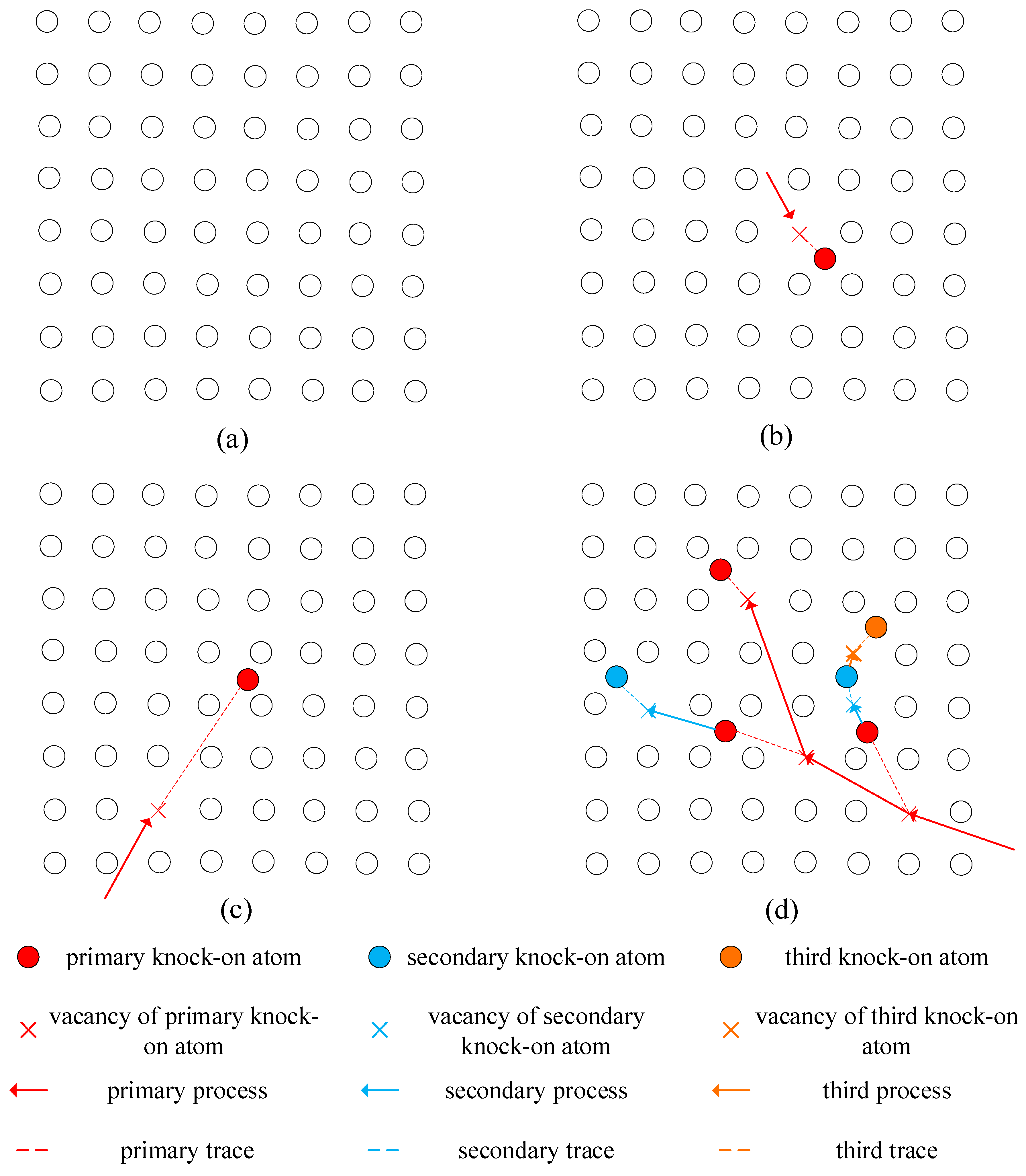
When the energy E received by the atom is below a certain threshold, it becomes confined to its initial lattice position due to hindrance from surrounding atoms and eventually dissipates through irregular thermal vibrations. In such cases, point defects cannot be formed. When the energy slightly exceeds this threshold, it becomes possible for the atom to overcome atomic hindrance and create a vacancy at its original lattice site. However, due to limited energy carried, significant displacement from the initial position is not feasible; instead, it remains in close proximity to the vacancy, forming a nearby Frenkel defect pair (Figure 2b). For higher values of energy E, substantial distances can be traversed within the solid before settling into a specific gap position, resulting in long-distance Frenkel defect pairs (Figure 2c). If an atom acquires sufficiently high energy E upon impact, it not only displaces itself but also triggers the dislocation of other lattice atoms, leading to a cascade of collisions. Eventually, after all moving atoms come to rest, several Frenkel defect pairs are formed (Figure 2d).

4. Atomic Displacement Model under Radiation

4.1. Development of Classical Models

Kinchin and Pease introduced the concept of displacements-per-atom, which elucidates that those energetic particles predominantly travel in a straight path within a material but occasionally engage in strong binary collisions, transferring energy to lattice atoms. Consequently, they further postulated graft collisions as a sequence of binary elastic interactions between atoms and proposed a methodology for estimating the number of displaced atoms (Nd) generated by a PKA with energy E.
N d =   0 0 < E < E d   1 E d < E < 2 E d E / 2 E d 2 E d < E < E 1   E 1 / 2 E d E 1 < E <
At energies above E1, the recoil only loses energy through electron excitation, while at energies below E1, the atoms are completely decelerated via hard-core elastic scattering. An atom that receives energy greater than the displacement threshold Ed is permanently displaced whereas an impacted atom receiving energy less than Ed eventually returns to its lattice position. The lattice effect is not considered in the process of single-atom displacement and cascade development. The Kinchin–Pease model assumes an irregular arrangement of atoms in a solid, disregarding the influence of crystal structure and defining the probability of atomic displacement as a step function.
P d T = 0 T < E d 1 T > E d
When utilizing this model, the fixed value is constrained within the range of 25 eV to 50 eV, with a preference for the lower value, which is commonly employed. This approximation proves highly advantageous when dealing with particles possessing minute cross-sections such as neutrons and electrons. In terms of ion and atom recoil, it is plausible for multiple simultaneous collisions to occur between neighboring atoms, resulting in what can be described as either a displacement spike or a heat spike. Building upon the Kinchin–Pease model, Nelson proposed a semi-empirical revision that incorporates several crucial modifications deemed significant [25].
N d = α β E W E γ E E f
Here, α is a factor introduced to incorporate realistic atomic scattering instead of the hard-core approximation, and it is generally recommended to maintain a value around 0.75. The factor β E was initially included to account for defect recombination within the cascade although it has often been disregarded by setting β E as equal to 1. The factor W E represents the fraction of initial PKA energy dissipated in elastic collisions. Focusing energy Ef serves as a parameter rather than displacement threshold Ed.
Robinson et al. improved the K-P model and derived the NRT model [10] as below:
N F P =   0 0 < E < E d   1 E d < E < 2 E d / 0.8 0.8 E / 2 E d 2 E d / 0.8 < E  
The difference between the formula and the K-P model incorporates compound correction when calculating the number of defects generated by high-energy PKA. It is noteworthy that both the K-P model and the NRT model demonstrate a proportional relationship between the number of defects produced and PKA energy. In cases of higher-energy PKAs, a significant portion of energy is dissipated through atom displacement and excitation, with this proportion increasing as PKA energy rises. Conversely, due to loss cascades caused by high-energy PKAs, there exists a considerably high defect density within cascade regions. Within dozens of picoseconds, most defects undergo compounding off, leaving only surviving defects contributing to irradiation losses. Consequently, the number of defects does not increase linearly with PKA energy; instead, final PKA energies typically range around several dozen keV.
The Arc-DPA (Athermal recombination corrected) model was released by the NEA Nuclear Materials Primary Radiation Damage Expert Group in 2015 [8]. It calculates DPA by considering the compound process within the cascade subsequent to its formation. The recombination process does not require thermal driving, meaning that there is no defect migration involved and defects remain fixed in place. This correction is based on molecular dynamics simulation data, likely obtained after the PKA produces a certain number of surviving defects for dozens of picoseconds. These surviving defects further contribute to permanent material damage and microstructure evolution under thermal motion drive, highlighting the significance of irradiation damage research. While still based on the NRT formula, modifications are made to account for PKA energy.
N F P =   0 0 < E < E d   1 E d < E < 2 E d / 0.8 0.8 E ξ E / 2 E d 2 E d / 0.8 < E  
Here, ξ E = 1 c E b 2 E d / 0.8 b + c is the correction coefficient under different energies and b and c in the equation are determined by the type of material. The equation quantifies the rate at which thermal recombination reduces the residual displacement damage to the saturation value of PKA energy, starting from the sub-cascade layer and increasing with energy.

4.2. New Method for Displacement Probability

The atoms occupying the regular lattice positions are situated within stable potential wells. In order for the colliding atoms to escape their respective potential wells, they must overcome the potential barrier created by the surrounding atoms. The highest point of this barrier is referred to as the saddle point while the difference in height between the saddle point and the lowest point of the potential well represents the barrier height or departure threshold energy. Due to its inherent directional and symmetrical nature, a crystal structure exhibits varying atomic barrier heights in all directions around its equilibrium position. Assuming that any further collisions by a primary knock-on atom (PKA) have no effect at energies below displacement threshold, Equation (8) describes the energy after nth collision.
T n = 1 4 M 1 M 2 M 1 + M 2 2 sin 2 α 2 × T n 1
Here, M 1 and M 2 are mass of particles in collision. And, transferred energy T reaches maximum at scattering angle α = 0 . The collision process is regarded as terminated when T n E d . It is evident that the variability in recoil angle α leads to variations in the number of displacement atoms, even when subjected to the same incident energy. The extent of damage inflicted on the crystalline medium is directly proportional to the uniform distribution of this energy. In Monte Carlo simulation, the number of collisions generated by each atom from its initial collision with other atoms until its energy falls below an offsite threshold determines the number of iterations since T n E d .
When an atom is displaced, a new iteration with its energy denoted as T1 and the count is re-evaluated. The total number of displaced atoms can be obtained by summing the product of the number of impacted atoms at each instance and their corresponding displacement probability (Pi).
N d = i = 1 n N i P i
The crystal structure of GaAs consists of two phases, namely sphalerite and monoclinic structures, with the latter being obtainable only under high-pressure conditions. The sphalerite structure belongs to the cubic crystal system, where cations are positioned at the center node along the vertical axis, resulting in a coordination number of 4 for both anions and cations. By considering the face-centered cube as a body-centered cube with stronger constraints on nearest-neighbor distance differences, it is observed that the probability of deviating from its original position is significantly lower than that of moving towards void directions among the eight connecting bond directions.
The atoms in the normal lattice position are confined within a stable potential well. For the energetically excited atoms to escape this potential well, they must overcome the barrier created by their surrounding atoms. The highest point of this barrier is known as the saddle point. The difference in height between the saddle point and the lowest point of the potential well represents the barrier height, which serves as an energy threshold for out-of-position events. Due to specific crystallographic directions and symmetries inherent in crystal structures, atomic barrier heights exhibit slight variations across different directions around equilibrium positions.
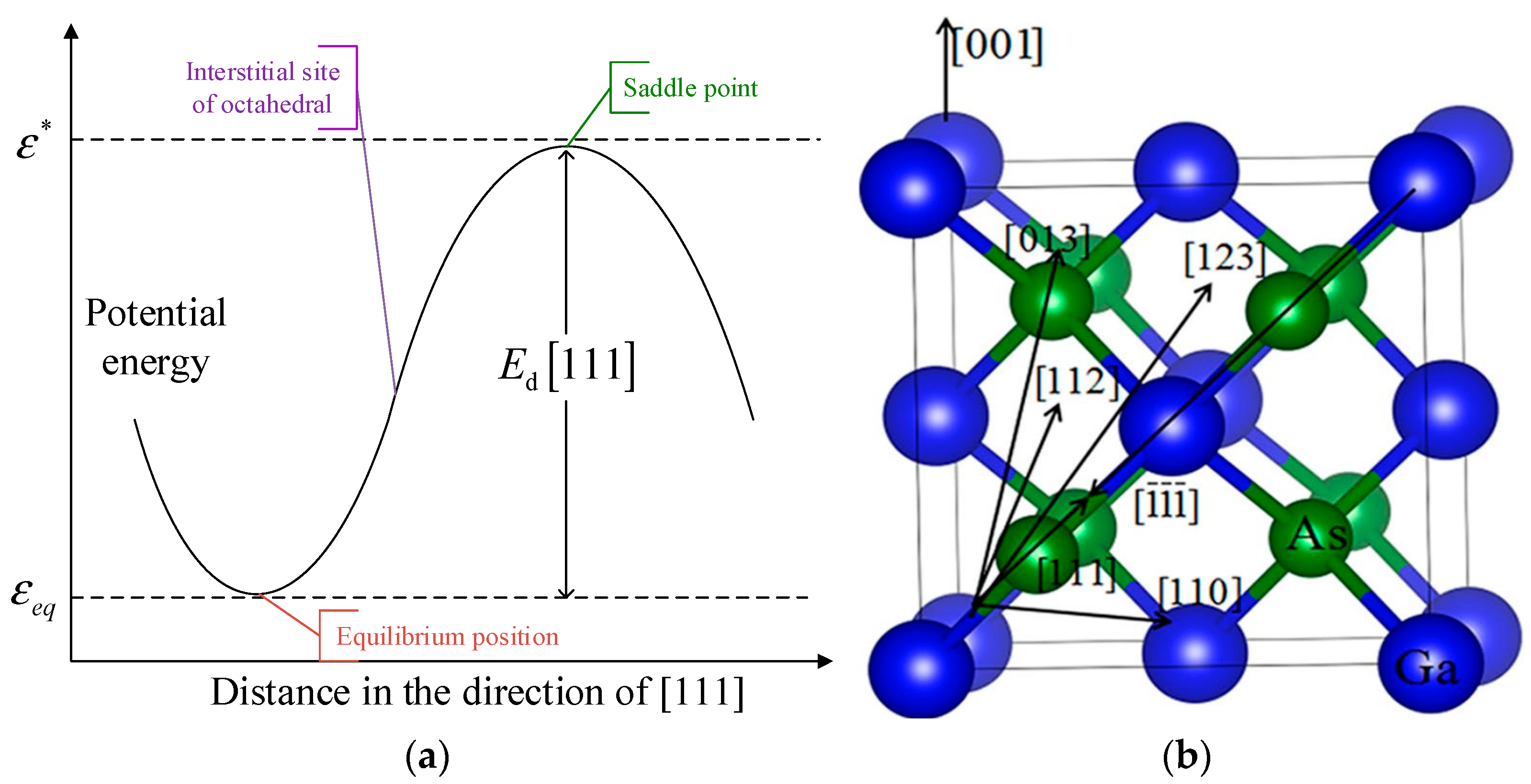
If we possess knowledge of the interaction potential function between lattice atoms, it is theoretically feasible to calculate each crystallographic direction’s respective barrier height or off-site threshold energy value. Let us assume that after a collision event, an atom located at the lower-left corner of Figure 3 gains energy and moves along the [111] direction. At every point along its trajectory representing its motion path upon impact, we superimpose interactions between this moving atom and all its nearest neighbor atoms, summing up interaction energies from the three adjacent face centers connected by the imaginary lines on the graph. At the center of the triangle formed by the dotted lines, total potential energy reaches its maximum value: namely, our barrier saddle point, with an energy level denoted as ε* (as shown in Figure 4a). The difference between ε*, representing energy at the saddle point, and εeq, representing the equilibrium position within the potential well, signifies displacement threshold energy within this particular direction.
The displacement threshold energy of Ga and As atoms along the six highly symmetrical directions [001], [110], [111], [013], [123], and [112] was calculated by Jiang et al. [26]. In the simulation, one of these six directions was randomly selected as a constraint condition for each collision. The high-symmetry direction in the GaAs bulk phase is illustrated in Figure 4b, and the corresponding results are presented in Table 1.
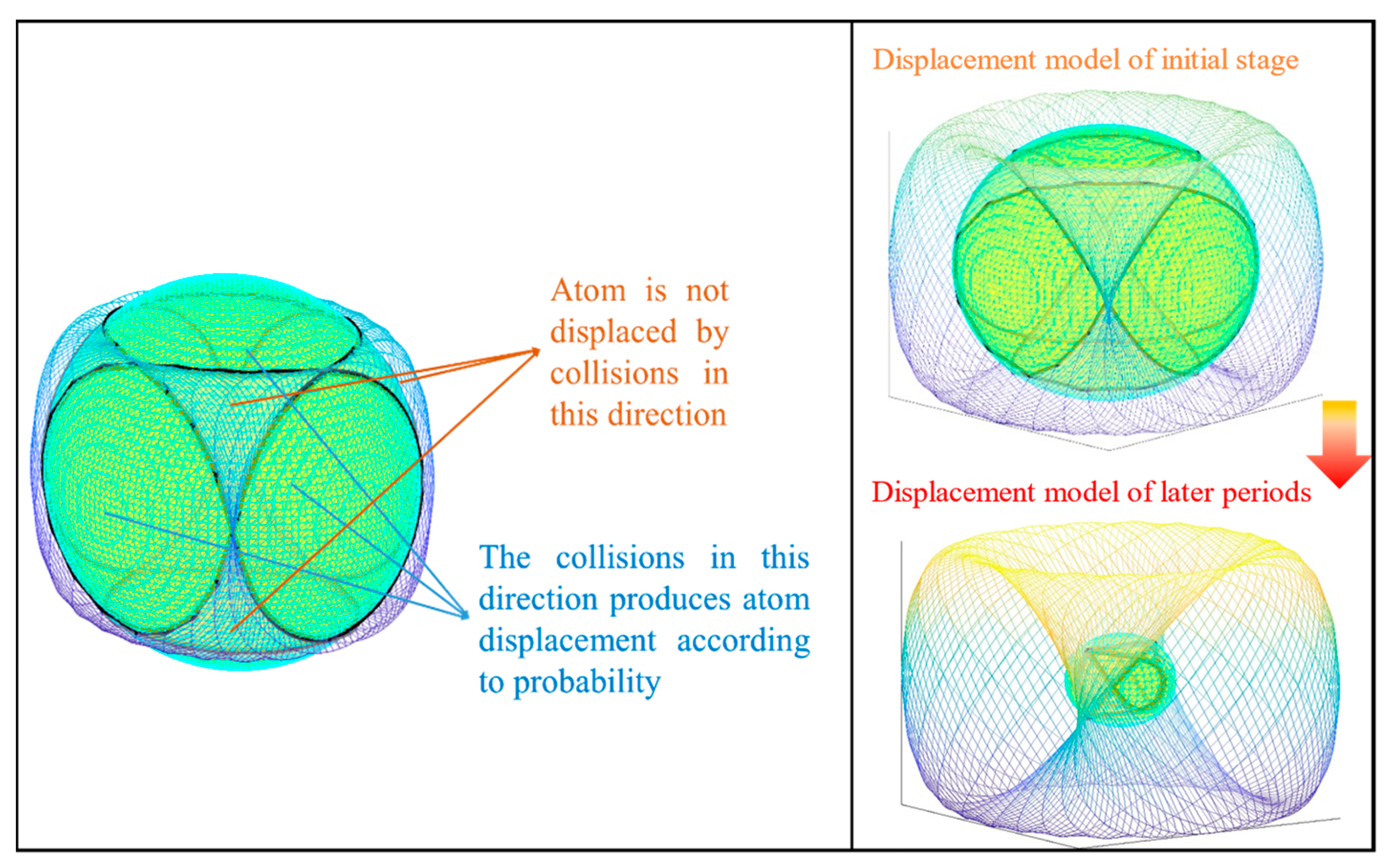
Therefore, in the sphalerite structure, the energy received (E) by the impacted atom during a collision is considered as the radius of a circle. This circle intersects with the Sine Surface to generate both stable and displacement regions, as depicted in Figure 5 The ratio of the displacement region to the entire sphere represents the probability of displacement for the impacted atom.
The probability distribution function of atomic displacement is established as below:
P d T =   0 T < E d , min ω c ω E E d , min <   T < E d , max   1 T > E d , max
The energy T carried by the atom is considered to be the radius of a sphere due to the random collision angle. As the number of collisions increases, the radius gradually decreases. When it falls below the minimum displacement threshold energy E d , min , no displacement occurs. Conversely, when it exceeds the maximum threshold energy E d , min , displacement becomes inevitable. For recoil atom energies within these upper and lower bounds, their probability can be determined by calculating the ratio of the spherical area ω c intersected with a sine surface to ω E , which represents the entire sphere.
The specific expression of Sine Surface function as the threshold limit of atomic collision probability model in GaAs is given below:
x = a sin u y = a sin v z = a sin ( u + v ) a = a 0 E coh 2 + E dis 2
Here, a 0 is the lattice constant and E dis is the displacement threshold energy in different directions. E coh is the cohesive energy to characterize the bonding strength between atoms in a crystal, which can be calculated by using the following Equation (12) [28].
E coh A B = n E ios A + m E ios B E A B n + m
The variables n and m represent the quantities of A and B atoms within the unit cell while Etotal (AB) signifies the overall energy of the compound. Additionally, Eiso(A) and Eiso(B) denote the energies of isolated A and B atoms, respectively.

4.3. The Displacement Threshold Energy Transfer Probability of Different Crystal Types

For certain indicators, there exists a disparity in the measurement outcomes among researchers across different time periods; however, this discrepancy also provides a range of values. Apart from variations in experimental conditions, the alteration of bond energy due to atomic vibrations during collisions contributes as a significant factor. High-energy particles experience successive collisions as they pass through the medium. After each collision, atoms exhibit specific vibrational frequencies without undergoing displacement, resulting in alterations in the bond energy between neighboring atoms and the displacement threshold energy in various directions. As a result, the likelihood of subsequent displacements occurring at the same position is modified based solely on prior collisions. This phenomenon can be considered as the transfer of different states between two data, and these discrete alterations are regarded as Markov processes. The nth collision results in the representation of displacement threshold energies corresponding to each direction utilizing state vector Sn.
S n = S n , 1     S n , 2     S n , i     S n , i + 1
To transfer state S n to state S n + m within m collisions, a state transition matrix is needed, which can be described as follows:
P = p 11 p 12 p 1 n p 21 p 22 p 2 n p n 1 p n 2 p n n
Pij denotes the probability of a single particle moving from state i to state j within a unit step. Since matrix P is a first-order isotropic Markov chain transfer matrix, it should satisfy the following condition:
j = 1 n p i j = 1 ,   p i j 0
It is worth noting that, using the [111] direction as an illustrative example, the maximum and minimum values reported in the previous literature represent state limits along with the presence of a displacement-threshold-energy probability transfer matrix. The interval from 8.5 to 16 is uniformly divided into multiple segments (with smaller intervals corresponding to higher incident particle energies). During simulation, a random value is selected as the displacement threshold energy, resulting in a state transition after each collision.
P E A s 111 = 8.5 9.6 10.7 11.8 12.9 14 15.1 16 0.5 0.5 0 0 0 0 0 0 0.5 0 0.5 0 0 0 0 0 0 0.5 0 0.5 0 0 0 0 0 0 0.5 0 0.5 0 0 0 0 0 0 0.5 0 0.5 0 0 0 0 0 0 0.5 0 0.5 0 0 0 0 0 0 0.5 0 0.5 0 0 0 0 0 0 0.5 0.5
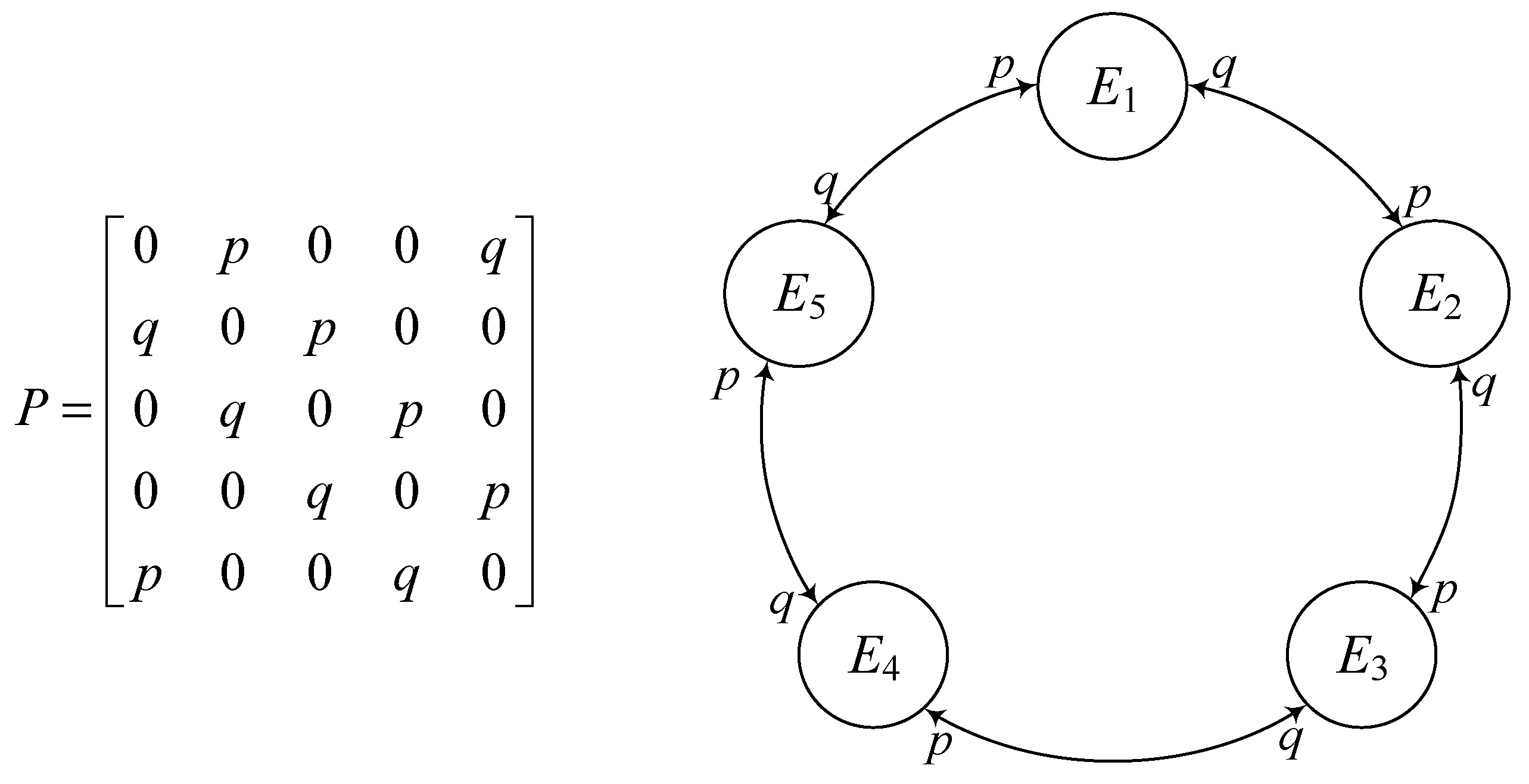
The transition probability is assigned equally to different states based on their distances, with states ranging from 8.5 eV to 16 eV being more likely to become adjacent states after collision. Figure 6 exhibits a bias towards the elastic barrier model wherein it tends to move towards the boundary states at both ends and either returns to an adjacent state or remains in the boundary state. The relationship between spacing and transition probability is described using a Gaussian distribution, indicating a preference for transitions towards adjacent states and higher likelihood of rebounding back to adjacent states upon reaching the boundaries. In cases of low-energy electron irradiation with minimal changes in displacement threshold energy after each impact, a circular random walk should be employed (refer to Figure 7).
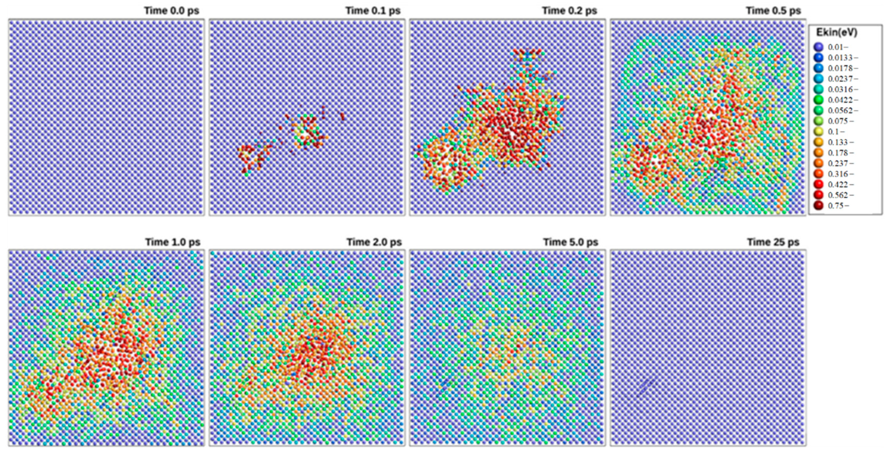
For materials with more metallic properties, or where the operating environment has a large temperature fluctuation (long period, low amplitude annealing process), atoms in lattice gaps can re-enter nearby vacancies, as shown in Figure 8. Initially, a significant number of atoms undergo displacement; however, upon the cooling down of the cascade, nearly all atoms reoccupy their ideal crystal positions due to the non-thermal recombination effect [32].
Clearly, a significant proportion of atoms do not return to their initial positions after irradiation. The number of atom substitutions far exceeds the number of defects generated, indicating a higher probability of defect formation compared to maintaining the original shape. Consequently, as irradiation progresses, the expected displacement threshold energy for colliding particles gradually decreases. In order to rectify this issue, it is necessary to transform the transition probability from being constant into a function. Ji H. and Yang S propose that the evolution of the semi-Markov process {r(t), t ≥ 0} is governed by the following probabilistic transitions [33].
Pr r t + h = j r t = i = λ i j h h + o h ,   r t jumps   from   i   to   j   1 + λ i i h h + o h ,   otherwise
Here, {r(t), t ≥ 0} is a continuous-time semi-Markov process taking values in a finite space; S = {1, 2, ···, N}, λij(h) is the transition rate from mode i to mode j at t when ij, λ i i h = j = 1 , i j N λ i j h , and o h is notation defined such that lim h 0 o h h = 0 .
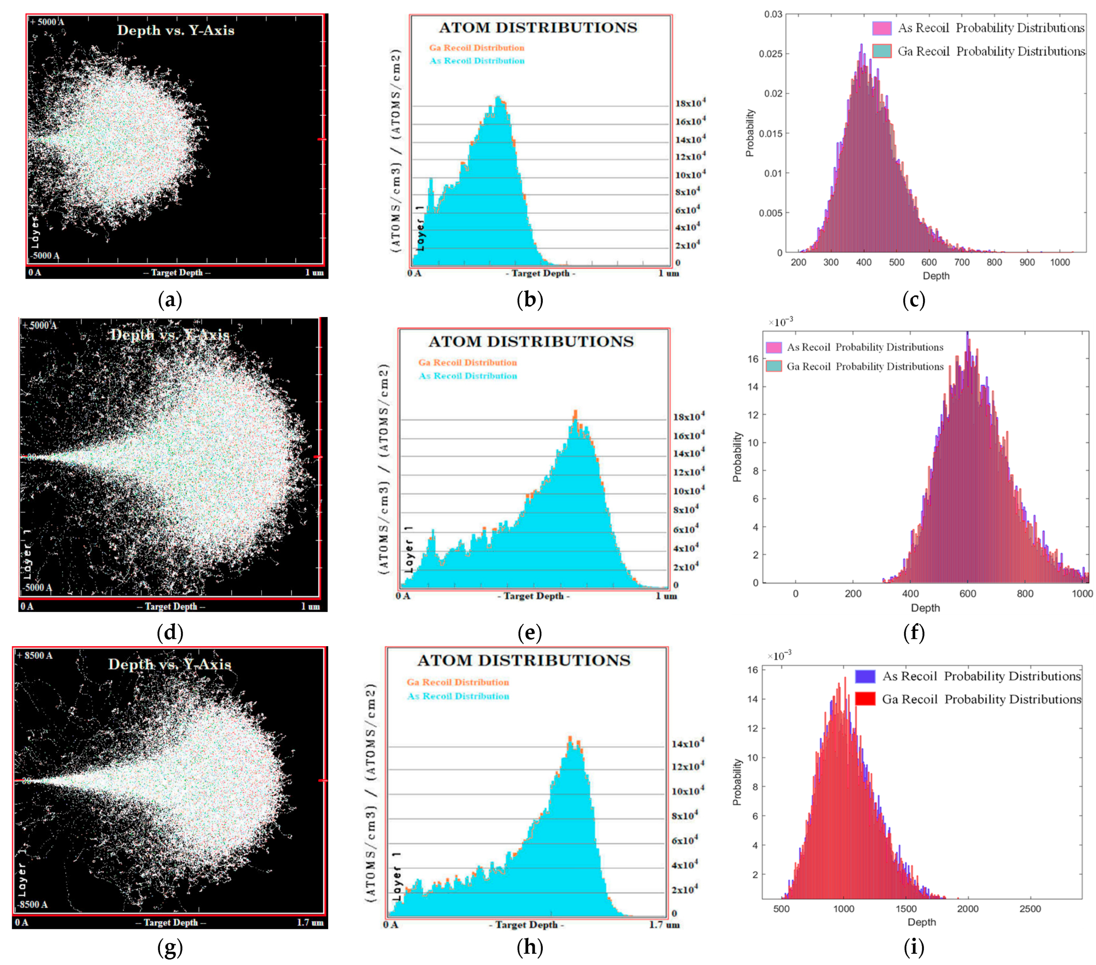
The GaAs solar cells in the space power system are subjected to high levels of proton irradiation energy, but their material does not undergo significant changes in electron trap and hole trap characteristics when annealed at low temperatures [34]. Therefore, the modified Elastic Barrier Random Walk (EBRW) model is suitable for describing the variation in crystal departure threshold energy. Figure 9 illustrates the number of displacement atoms obtained using different methods. Compared to the other three linear models, our proposed method aligns more closely with the arc-NRT model. Additionally, the gradual increase in proton irradiation at low energies reflects the uncertainty associated with multi-directional ionization threshold energy during collisions. Utilizing protons with different energies to produce primary knock-on atom (PKA) energies of 50 keV, 100 keV, and 150 keV as per Equation (12), the results depicted in Figure 10 illustrate that after 10,000 repeated impacts, the proposed method consistently presents a lower count of F-pairs in comparison to the predictions of the NRT model. This discrepancy can be attributed to incorporating displacement threshold energy and defect reset into our approach. Furthermore, the study revealed a higher concentration of atom distribution under various incident proton energies compared to more dispersed results obtained through SRIM calculations.

5. Conclusions

Based on the existing crystal irradiation defect model, a novel defect number calculation model is proposed that incorporates variations in crystal type and deviation threshold energy across different crystal directions. To account for the uncertainty caused by differences in departure threshold energy for different impact directions, an example using GaAs establishes a single-collision atomic displacement probability model for the face-centered cubic type and provides the corresponding calculation formula for displacement probability. Additionally, the Markov process is introduced to describe the state transition process of cohesive energy and threshold displacement energy for each crystal orientation under continuous collision. Three probabilistic transition models are presented that comprehensively consider different crystal types, irradiation intensity, and vacancy recovery after annealing. The results demonstrate that as energy increases, this method yields defect numbers similar to those obtained by using the arc-NRT model but with a higher degree of accuracy than linear models. Moreover, the resulting probability distribution aligns closely with SRIM simulation results. These findings indicate that the proposed new model effectively captures nonlinear growth trends arising from displacement excitation energy loss and phonon excitation.

Author Contributions

Conceptualization, T.Z.; methodology, T.Z. and H.-Z.H.; validation, Y.Z., Y.-F.L. and S.G.N.; investigation, Y.Z.; resources, Y.-F.L.; data curation, Y.Z.; writing—original draft preparation, T.Z.; writing—review and editing, T.Z. and S.G.N.; supervision, H.-Z.H.; project administration, H.-Z.H.; funding acquisition, H.-Z.H. All authors have read and agreed to the published version of the manuscript.

Funding

This research was funded by the National Key Research and Development Program of China under the contract No. 2020YFB2008900.

Institutional Review Board Statement

Not applicable.

Informed Consent Statement

Not applicable.

Data Availability Statement

The datasets generated during and/or analyzed during the current study are available from the corresponding author upon reasonable request.

Conflicts of Interest

The authors declare that they have no known competing financial interests or personal relationships that could have appeared to influence the work reported in this paper.

References

  1. Kim, D.H.; Lee, J.H.; Son, S.K. Band-structure simulations for overlap wave functions between electrons and holes for recombination in undoped GaAs/AlGaAs heterostructures. J. Korean Phys. Soc. 2022, 80, 161–166. [Google Scholar] [CrossRef]
  2. Kaczmarek, S.M. Recharging processes of active ions and radiation defects in some laser crystals doped with RE and TM ions under proton irradiation. Opt. Mater. 2007, 29, 1400–1407. [Google Scholar] [CrossRef]
  3. Kinchin, G.H.; Pease, R.S. The Displacement of atoms in solids by radiation. Rep. Prog. Phys. 1955, 18, 1329–1334. [Google Scholar] [CrossRef]
  4. Olander, D.R. Molecular Beam Sources Fabricated from Multichannel Arrays. III. The Exit Density Problem. J. Appl. Phys. 1970, 41, 2769–2776. [Google Scholar] [CrossRef]
  5. Robinson, M.T. Computer simulation studies of high-energy collision cascades. Nucl. Instr. Meth. Phys. Res. B 1992, 67, 396–400. [Google Scholar] [CrossRef]
  6. Nordlund, K. Historical review of computer simulation of radiation effects in materials. J. Nucl. Mater. 2019, 520, 273–295. [Google Scholar] [CrossRef]
  7. Norgett, M.J.; Robinson, M.T.; Torrens, I.M. A proposed method of calculating displacement dose rates. Nucl. Eng. Des. 1975, 33, 50–54. [Google Scholar] [CrossRef]
  8. Nordlund, K.H.; Sand, A.E.; Granberg, F.G.; Zinkle, S. Primary radiation damage in materials: Review of current understanding and proposed new standard displacement damage model to incorporate in cascade defect production efficiency and mixing effects. OECD Nucl. Energy Agency 2015, 9, 1–87. [Google Scholar]
  9. Robinson, M.T.; Torrens, I.M. Computer simulation of atomic-displacement cascades insolids in the binary-collision approximation. Phys. Rev. B 1974, 9, 5008. [Google Scholar] [CrossRef]
  10. Robinson, M.T.; Oen, O.S. On the use of thresholds in damage energy calculations. J. Nucl. Mater. 1982, 110, 147–149. [Google Scholar] [CrossRef]
  11. Biersack, J.P.; Haggmark, L.G. A Monte Carlo computer program for the transport of energetic ions in amorphous targets. Nucl. Instr. Meth. 1980, 174, 257–269. [Google Scholar] [CrossRef]
  12. Ziegler, J.F.; Ziegler, M.D.; Biersack, J.P. SRIM-The stopping and range of ions in matter. Nucl. Instr. Meth. Phys. Res. B 2010, 268, 1818–1823. [Google Scholar] [CrossRef]
  13. Posselt, M.; Biersack, J. Computer simulation of ion implantation into crystal inetargets. Nucl. Instr. Meth. Phys. Res. B 1992, 64, 706–710. [Google Scholar] [CrossRef]
  14. Posselt, M. Computer simulation of channeling implantation at high and mediumenergies. Nucl. Instr. Meth. Phys. Res. B 1993, 80, 28–32. [Google Scholar] [CrossRef]
  15. Djurabekova, F.G.; Pugacheva, T.S.; Umarov, F.F.; Yugay, S.V. Computer Simulation of Ion Implantation with Visual Observation of the Implantation Profiles. In Proceedings of the Conference on Ion Implantation Technology IEEE, Alpbach, Austria, 17–22 September 2000; pp. 228–231. [Google Scholar] [CrossRef]
  16. Schiettekatte, F. Fast Monte Carlo for ion beam analysis simulations. Nucl. Instr. Meth. Phys. Res. B 2008, 266, 1880–1885. [Google Scholar] [CrossRef]
  17. Wang, F.; Adolphsen, C.; Nantista, C. Performance limiting effects in X-band accelerators. Phys. Rev. Accel. Beams 2011, 14, 010401. [Google Scholar] [CrossRef]
  18. Available online: https://www-nds.iaea.org/CRPdpa/ (accessed on 15 May 2022).
  19. Wang, Z.; Muránsky, O.; Zhu, H. Impact of pre-existing crystal lattice defects on the accumulation of irradiation-induced damage in a C/C composite. J. Nucl. Mater. 2022, 546, 153684. [Google Scholar] [CrossRef]
  20. Karavaev, A.V.; Dremov, V.V.; Ionov, G.V. Equilibrium thermodynamics of radiation defect clusters in δ-phase Pu–Ga alloys. J. Nucl. Mater. 2016, 468, 46–55. [Google Scholar] [CrossRef]
  21. Yang, Y.; Li, J. Monte Carlo simulation of pka distribution along nanowires under ion radiation. Nucl. Eng. Des. 2018, 340, 300–307. [Google Scholar] [CrossRef]
  22. Zobelli, A.; Gloter, A.; Ewels, C.P.; Seifert, G.; Colliex, C. Electron knock-on cross section of carbon and boron nitride nanotubes. Phys. Rev. B 2007, 75, 245402. [Google Scholar] [CrossRef]
  23. Sadigh, B.; Lenosky, T.J.; Theiss, S.K. Mechanism of Boron Diffusion in Silicon: An Ab Initio and Kinetic Monte Carlo Study. Phys. Rev. Lett. 1999, 83, 4341–4344. [Google Scholar] [CrossRef]
  24. Nordlund, K.; Averback, R.S. Role of Self-Interstitial Atoms on the High Temperature Properties of Metals. Phys. Rev. Lett. 1998, 80, 4201–4204. [Google Scholar] [CrossRef]
  25. Nelson, R.S. Ion implantation in semiconductors. AERE Rep. 1969, 20, 165. [Google Scholar] [CrossRef]
  26. Jiang, M.; Xiao, H.Y.; Peng, S.M. A comparative study of low energy radiation response of AlAs, GaAs and GaAs/AlAs superlattice and the damage effects on their electronic structures. Sci. Rep. 2018, 8, 2012. [Google Scholar] [CrossRef] [PubMed]
  27. Sayed, M.; Jefferson, J.H.; Walker, A.B. Computer simulation of atomic displacements in Si, GaAs, and AlAs. Nucl. Instr. Meth. Phys. Res. B 1995, 102, 232–235. [Google Scholar] [CrossRef]
  28. Li, J.; Porter, L.; Yip, S. Atomistic modeling of finite-temperature properties of crystalline β-SiC: II. Thermal conductivity and effects of point defects. J. Nucl. Mater. 1998, 255, 139–152. [Google Scholar] [CrossRef]
  29. Zollo, G.; Tarus, J.; Nieminen, R.M. Reliability of analytical potentials for point-defect simulation in GaAs. J. Phys. Condens. Matter 2004, 16, 3923–3932. [Google Scholar] [CrossRef]
  30. Ihm, J.; Joannopoulos, J.D. Ground-state properties of GaAs and AlAs. Phys. Rev. B 1981, 24, 4191–4197. [Google Scholar] [CrossRef]
  31. Ahmed, R.; Hashemifar, S.; Akbarzadeh, H. Ab initio study of structural and electronic properties of III-arsenide binary compounds. Comput. Mater. Sci. 2007, 39, 580–586. [Google Scholar] [CrossRef]
  32. Nordlund, K.; Zinkle, S.J.; Sand, A.E.; Granberg, F. Primary radiation damage: A review of current understanding and models. J. Nucl. Mater. 2018, 512, 450–479. [Google Scholar] [CrossRef]
  33. Ji, H.; Yang, S. Stochastic Stability of Semi-Markov Jump Linear Systems: An LMI Approach. In Proceedings of the 50th IEEE Conference on Decision and Control and European Control Conference, Orlando, FL, USA, 12–15 December 2011; pp. 4668–4673. [Google Scholar] [CrossRef]
  34. Li, S.S.; Chiu, T.T.; Loo, R.Y. Effects of Low Temperature Periodic Annealing on the Deep-Level Defects in 200 KeV Proton Irradiated AlGaAs-GaAs Solar Cells. IEEE Trans. Nucl. Sci. 1981, 28, 4113–4118. [Google Scholar] [CrossRef]
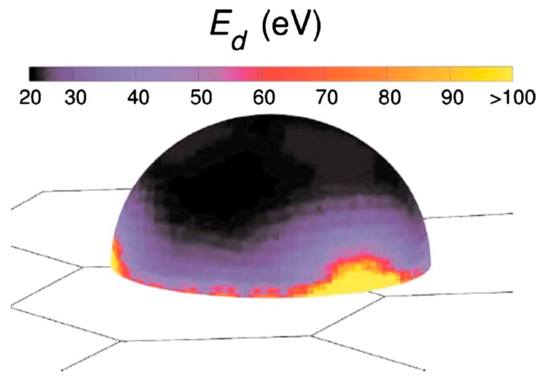
Figure 1. The displacement energy varies with the displacing direction in the carbon nanotube [22].
Applsci 13 10701 g001
Figure 2. Schematic diagram of lattice damage by irradiation. (a) Complete lattice. (b) Close Frenkel pairs. (c) Distant Frenkel pairs. (d) Cascading-collision Frenkel pairs.
Applsci 13 10701 g002
Figure 3. The situation of recoil-atom displacement in sphalerite structures.
Applsci 13 10701 g003
Figure 4. Out-of-position threshold energy and orientation in a crystal structure. (a) [111] direction displacement threshold energy obtained from the difference between the energy at the saddle point and the energy of the potential well at the atomic equilibrium position. (b) High-symmetry direction in the GaAs bulk phase [26].
Applsci 13 10701 g004
Figure 5. Displacement probability model of impacted atom.
Applsci 13 10701 g005
Figure 6. Elastic barrier random walk model state diagram and its probability transition matrix.
Applsci 13 10701 g006
Figure 7. Circular random walk state diagram and its probability transition matrix.
Applsci 13 10701 g007
Figure 8. Collision cascade induced by a 10 keV recoil in Fe at an ambient temperature of 0 K [32].
Applsci 13 10701 g008
Figure 9. Variation rule of defect number under different methods.
Applsci 13 10701 g009
Figure 10. Distribution of defects and recoil atoms in GaAs irradiated by protons with different energies. (a) Defect distribution for 50 KeV PKA impact. (b) Defect distribution for 50 KeV PKA impact. (c) Probability distribution under the proposed method for 50 KeV PKA impact. (d) Defect distribution for 100 KeV PKA impact. (e) Defect distribution for 100 KeV PKA impact. (f) Probability distribution under the proposed method for 100 KeV PKA impact. (g) Defect distribution for 150 KeV PKA impact. (h) Defect distribution for 150 KeV PKA impact. (i) Probability distribution under the proposed method for 150 KeV PKA impact.
Applsci 13 10701 g010
Table 1. Displacement threshold energy, lattice constant, and cohesive energy of GaAs.
Displacement Threshold in GaAs (eV)
Crystal OrientationGaAs
[001]14.5 [26], 14 [27]10 [26], 16 [27]
[110]12 [26], 16 [27]10 [26], 20 [27]
[111]12 [26], 16 [27]8.5 [26], 16 [27]
[013]17.5 [26]12 [26]
[112]22.5 [26]10 [26]
[123]30 [26]10 [26]
Lattice constant5.66 [28], 5.65 [29]
Cohesive energy3.7 [30], 3.18 [31], 3.35 [29]
Disclaimer/Publisher’s Note: The statements, opinions and data contained in all publications are solely those of the individual author(s) and contributor(s) and not of MDPI and/or the editor(s). MDPI and/or the editor(s) disclaim responsibility for any injury to people or property resulting from any ideas, methods, instructions or products referred to in the content.