
Vision- and Lidar-Based Autonomous Docking and Recharging of a Mobile Robot for Machine Tending in Autonomous Manufacturing Environments


Abstract
:1. Introduction
- This paper aims to develop a vision–Lidar data fusion method for mobile robots to achieve accurate autonomous docking and recharging in a manufacturing environment.
- This paper contributes to the transition of state-of-the-art real-time object detection methods from general public datasets to real-world manufacturing tasks by combining deep-learning-based techniques to identify charging stations in a complex manufacturing environment; we then use a Lidar-based approach to localize the detected wireless charger and dock the mobile robot to it for recharging.
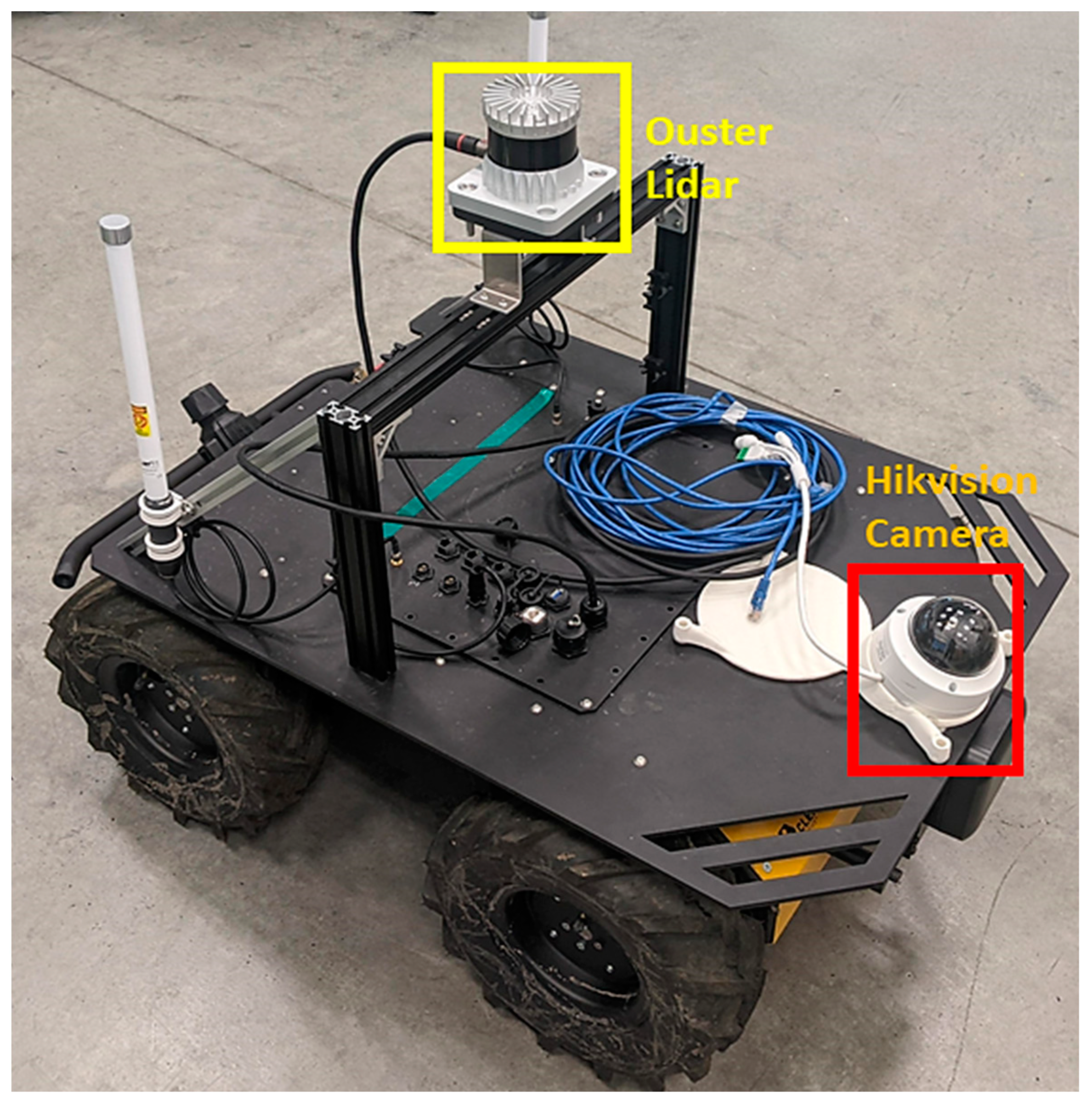
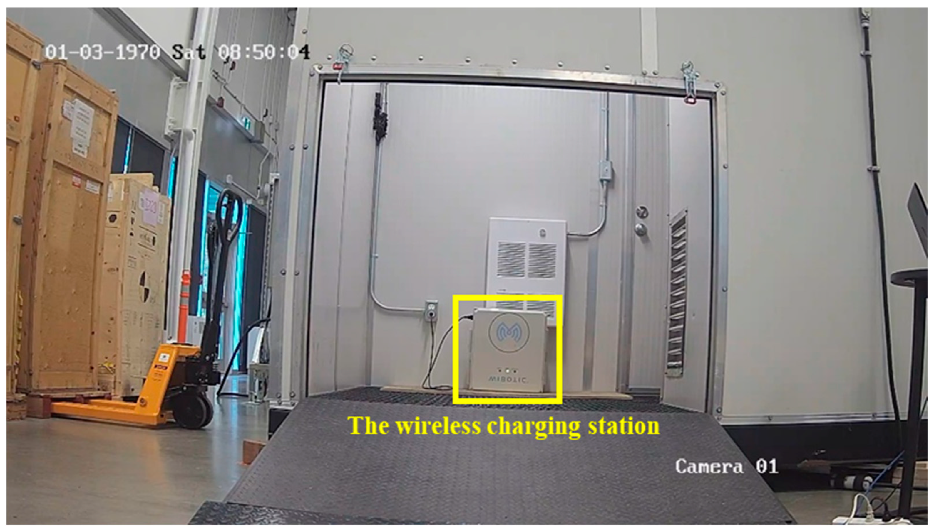
- An indoor manufacturing environment with an enclosed space where a wireless charging station is situated is considered for the implementation of the docking procedure. The proposed method is analyzed and discussed based on the autonomous docking and recharging of a Husky robot made by Clearpath Robotics.
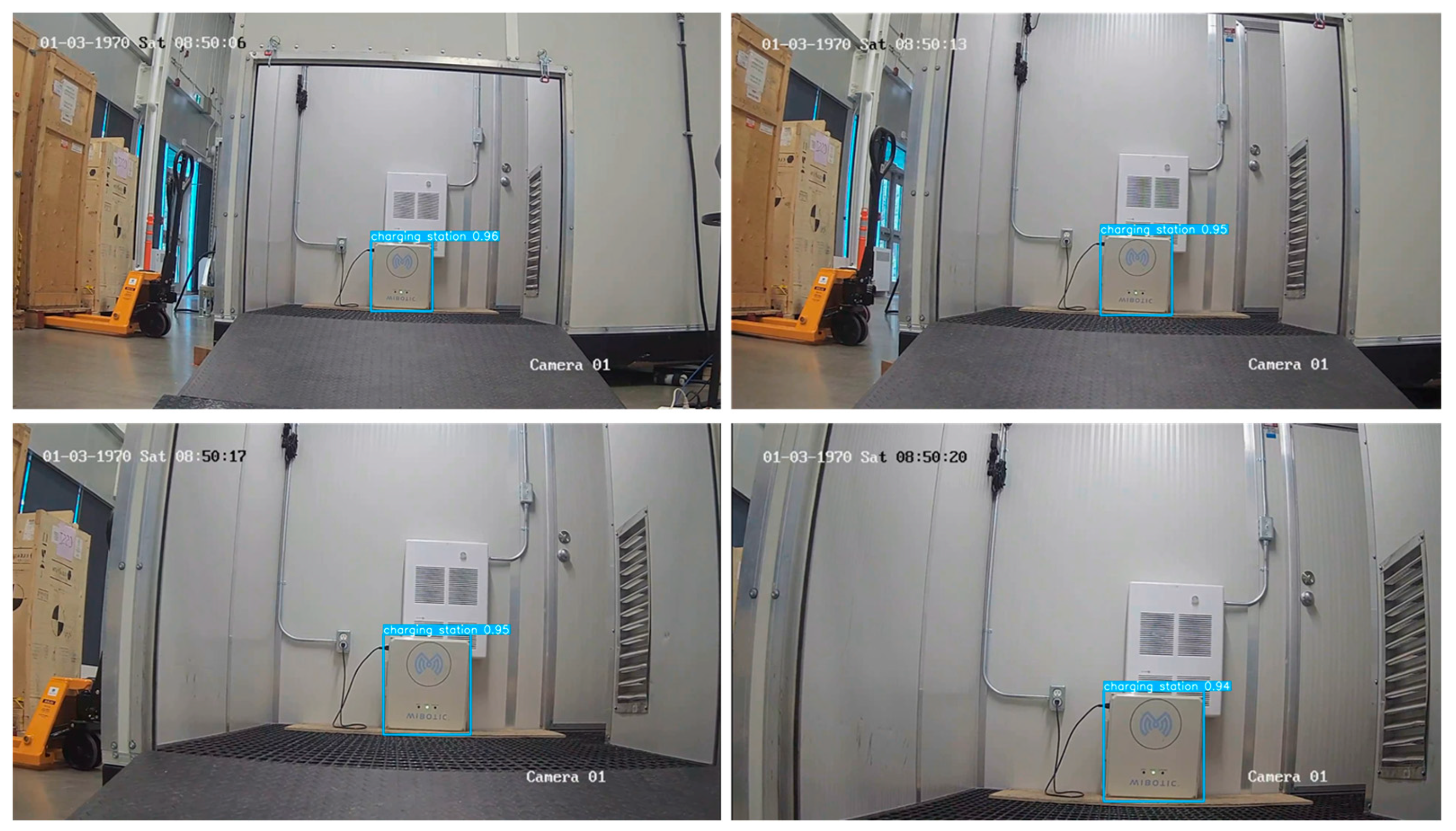
- A YOLOv7-based method is used to detect the charging station for the robot to navigate to the desired location. The process of planning a path to the charger can be achieved with waypoints using the SLAM method, which is not discussed in this paper. Afterward, the Lidar sensor is used, along with the detected results from the camera, to determine the distance from the charger and side wall to achieve an accurate pose estimation and then successfully dock the robot to the charging station. The proposed method can be easily adapted to different types and numbers of wireless chargers in a manufacturing environment. The distance data between the Lidar and the camera can be calibrated to achieve accurate alignment and pose estimation.
2. Related Work
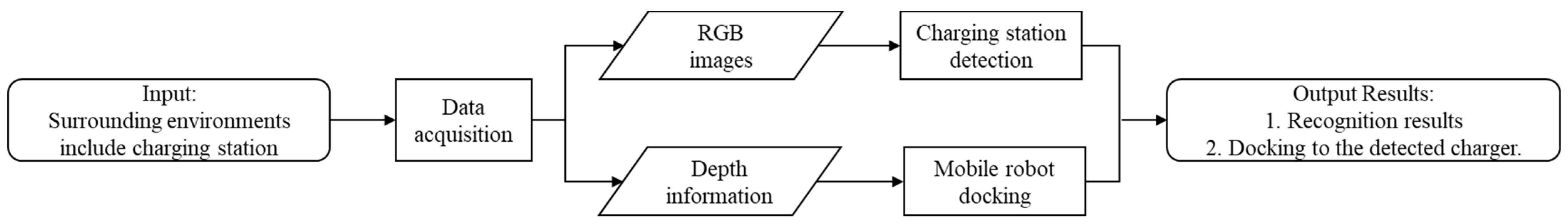
3. System Overview
4. Proposed Method
4.1. YOLOv7 Architecture
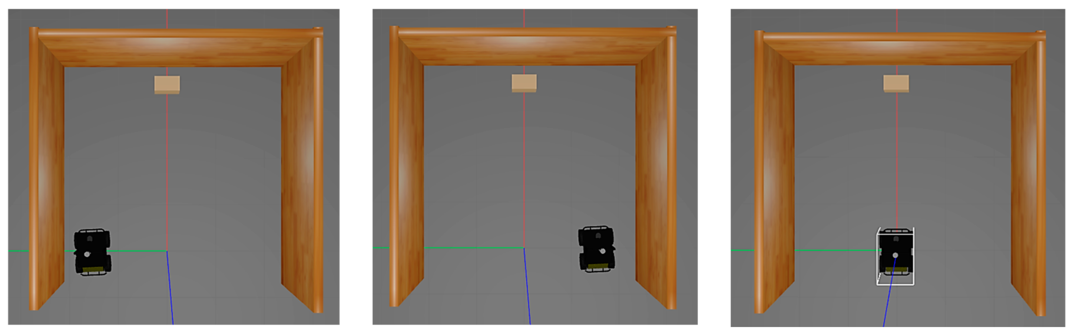
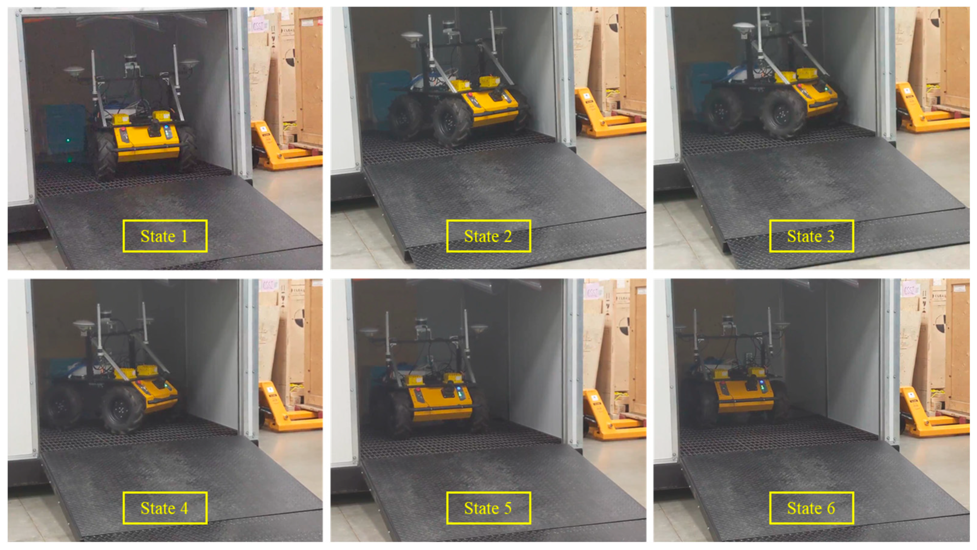
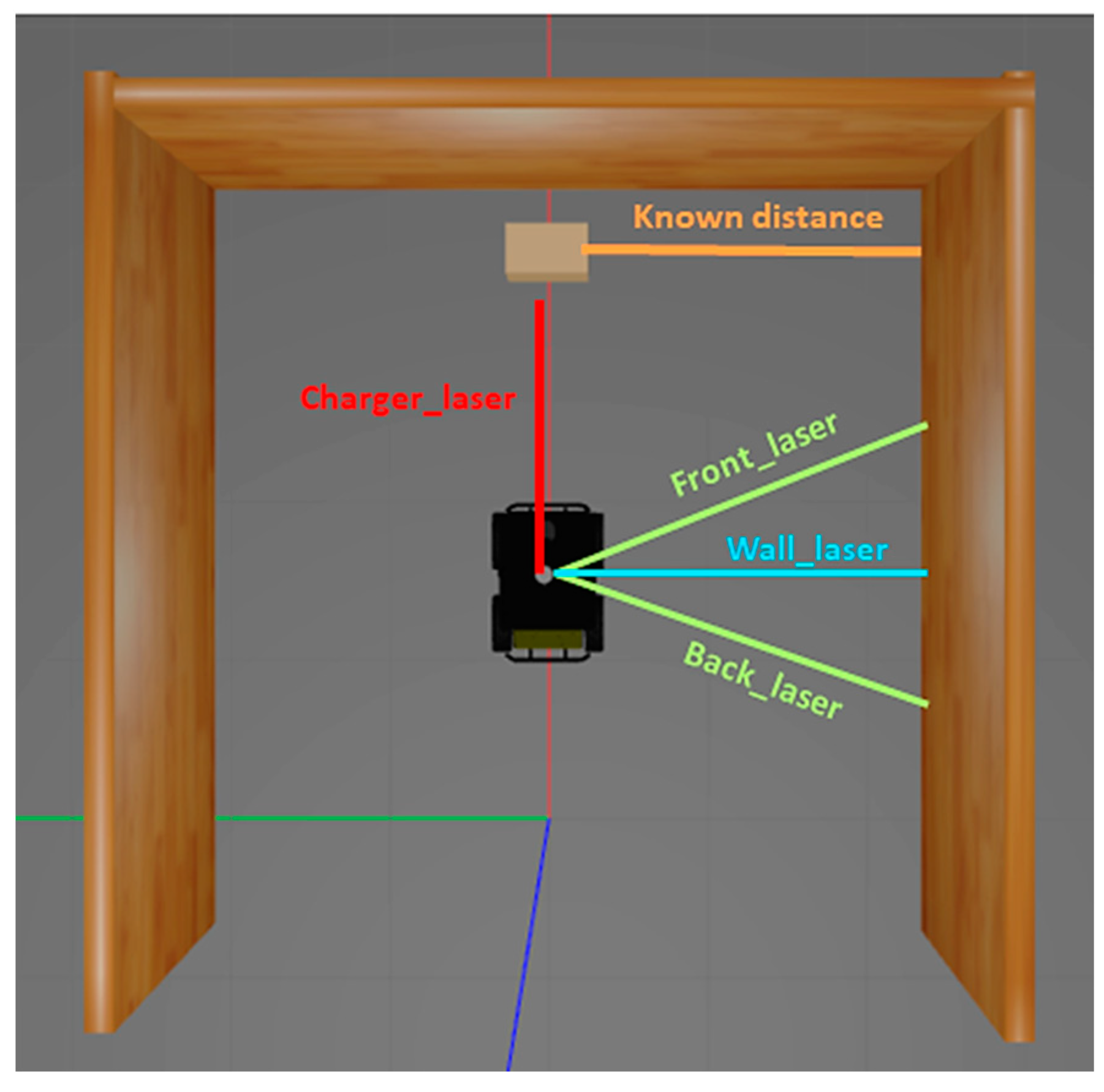
4.2. Lidar and Vision Data Fusion Method for Autonomous Docking
| Algorithm 1. Lidar-based docking. |
| State 1: Robot straightening |
| Initialize Front_laser, Back_laser, Charger_laser, and Wall_laser |
| If (Front_laser − Back_laser) > 0 then rotate clockwise until Front_laser = Back_laser |
| elseif (Front_laser − Back_laser) < 0 then rotate anti-clockwise until Front_laser = Back_laser |
| If Wall_laser >known_distance |
| Change state to 3 |
| esleif Wall_laser <known_distance |
| Change state to 2 |
| State 2: Robot turning left if to the right of the charger |
| Turn the robot anti-clockwise until Back_laser = Wall_laser |
| Then change state to 4 |
| State 3:Robot turning right if to the left of the charger |
| Turn the robot clockwise until Front_laser = Wall_laser |
| Then change state to 4 |
| State 4:Robot’s linear motion |
| Move robot in a linear motion until Wall_laser = known_distance |
| Then change state to 5 |
| State 5: Robot straightening second time |
| If (Front_laser − Back_laser) > 0 then rotate clockwise until Front_laser = Back_laser |
| elseif (Front_laser − Back_laser) < 0 then rotate anti-clockwise until Front_laser = Back_laser |
| Then change state to 6 |
| State 6:Robot moving towards the charger |
| Move robot in a linear motion until charger_laser within 2 to 3 cm’s away from the charger |
| Then change state to 7 |
| State 7:Robot docking with the charger |
| Stop the robot’s motion and change status to docked |
5. Results
5.1. Transfer Learning and Data Augmentation
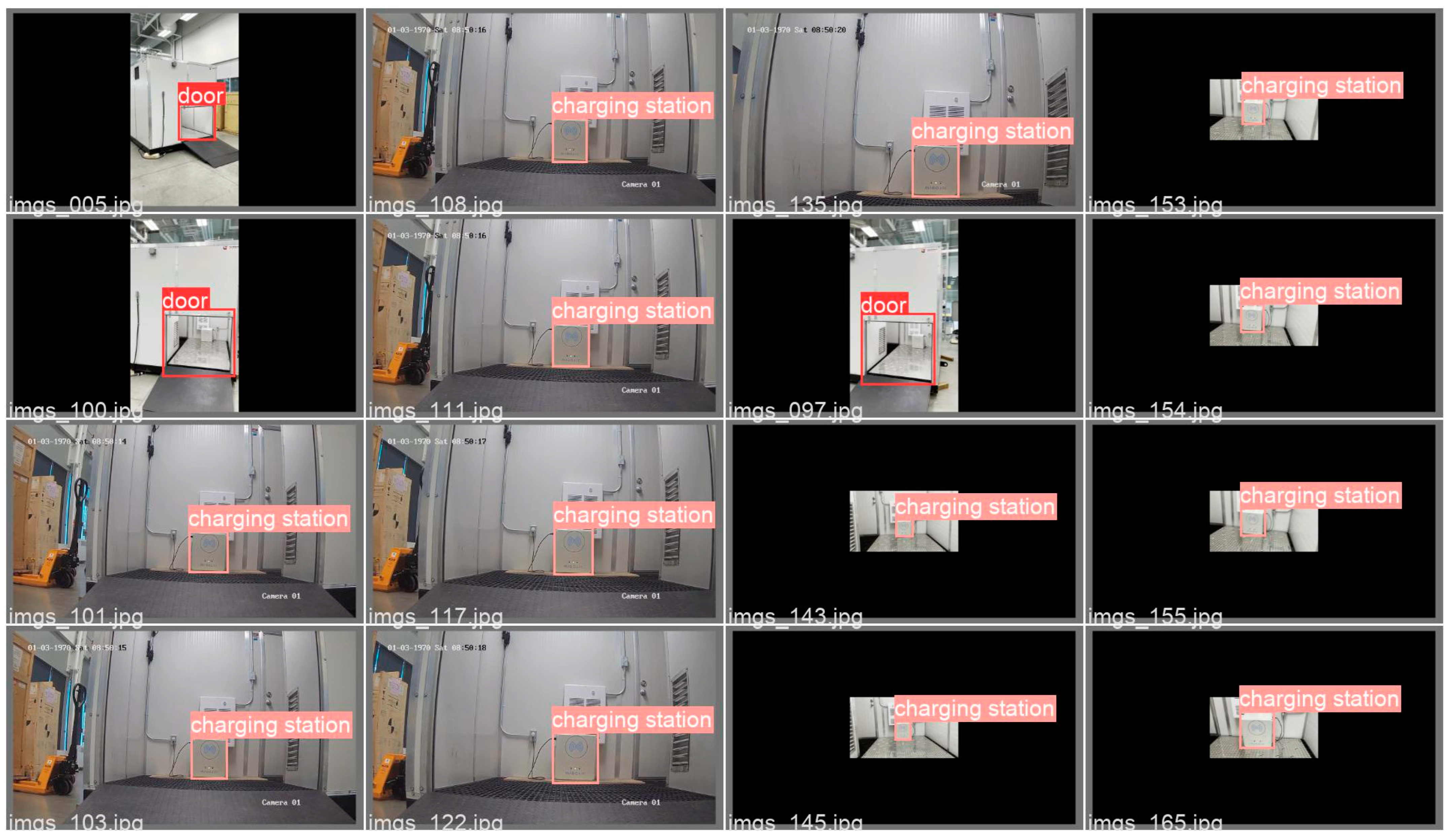
5.2. Datasets Building
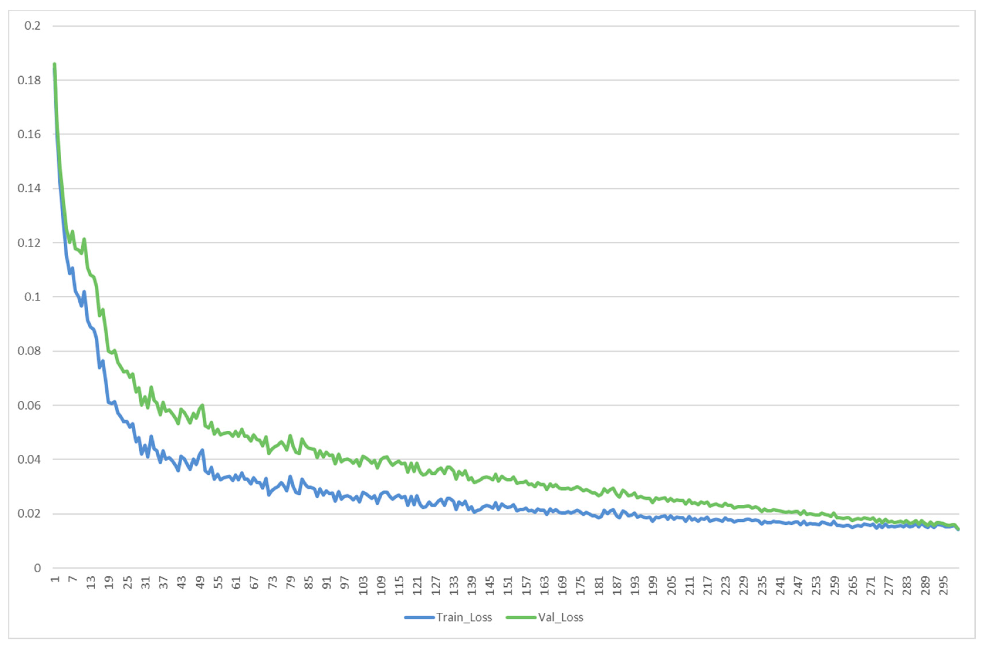
5.3. Training Environment and Parameters
5.4. Results and Analysis
5.4.1. Evaluation Metrics
5.4.2. Results
6. Discussion and Conclusions
Author Contributions
Funding
Institutional Review Board Statement
Informed Consent Statement
Data Availability Statement
Acknowledgments
Conflicts of Interest
References
- Vargas, J.; Alsweiss, S.; Toker, O.; Razdan, R.; Santos, J. An Overview of Autonomous Vehicles Sensors and Their Vulnerability to Weather Conditions. Sensors 2021, 21, 5397. [Google Scholar] [CrossRef] [PubMed]
- Rashid, E.; Ansari, M.D.; Gunjan, V.K.; Ahmed, M. Improvement in extended object tracking with the vision-based algorithm. Stud. Comput. Intell. 2020, 885, 237–245. [Google Scholar] [CrossRef]
- Jia, F.; Tzintzun, J.; Ahmad, R. An Improved Robot Path Planning Algorithm for a Novel Self-adapting Intelligent Machine Tending Robotic System. In Mechanisms and Machine Science; Springer International Publishing: Cham, Switzerland, 2020; Volume 86, pp. 53–64. ISBN 9783030454029. [Google Scholar]
- Yao, C.; Li, Y.; Ansari, M.D.; Talab, M.A.; Verma, A. Optimization of industrial process parameter control using improved genetic algorithm for industrial robot. Paladyn 2022, 13, 67–75. [Google Scholar] [CrossRef]
- Guangrui, F.; Geng, W. Vision-based autonomous docking and re-charging system for mobile robot in warehouse environment. In Proceedings of the 2017 2nd International Conference on Robotics and Automation Engineering (ICRAE), Shanghai, China, 29–31 December 2017; pp. 79–83. [Google Scholar] [CrossRef]
- Rubio, F.; Valero, F.; Llopis-Albert, C. A review of mobile robots: Concepts, methods, theoretical framework, and applications. Int. J. Adv. Robot. Syst. 2019, 16, 1–22. [Google Scholar] [CrossRef]
- Abbasi, R.; Martinez, P.; Ahmad, R. The digitization of agricultural industry—A systematic literature review on agriculture 4.0. Smart Agric. Technol. 2022, 2, 100042. [Google Scholar] [CrossRef]
- Maddikunta, P.K.R.; Pham, Q.-V.; Prabadevi, B.; Deepa, N.; Dev, K.; Gadekallu, T.R.; Ruby, R.; Liyanage, M. Industry 5.0: A survey on enabling technologies and potential applications. J. Ind. Inf. Integr. 2022, 26, 100257. [Google Scholar] [CrossRef]
- Liu, Y. A Laser Intensity Based Autonomous Docking Approach for Mobile Robot Recharging in Unstructured Environments. IEEE Access 2022, 10, 71165–71176. [Google Scholar] [CrossRef]
- Doumbia, M.; Cheng, X.; Havyarimana, V. An Auto-Recharging System Design and Implementation Based on Infrared Signal for Autonomous Robots. In Proceedings of the 2019 5th International Conference on Control, Automation and Robotics (ICCAR), Beijing, China, 19–22 April 2019; IEEE: Piscataway, NJ, USA, 2019; pp. 894–900. [Google Scholar]
- Luo, R.C.; Liao, C.T.; Lin, S.C. Multi-sensor fusion for reduced uncertainty in autonomous mobile robot docking and recharging. In Proceedings of the 2009 IEEE/RSJ International Conference on Intelligent Robots and Systems, St. Louis, MO, USA, 10–15 October 2009; pp. 2203–2208. [Google Scholar] [CrossRef]
- Khan, S.; Wollherr, D.; Buss, M. Modeling Laser Intensities for Simultaneous Localization and Mapping. IEEE Robot. Autom. Lett. 2016, 1, 692–699. [Google Scholar] [CrossRef]
- Hadi, R.H.; Hady, H.N.; Hasan, A.M.; Al-Jodah, A.; Humaidi, A.J. Improved Fault Classification for Predictive Maintenance in Industrial IoT Based on AutoML: A Case Study of Ball-Bearing Faults. Processes 2023, 11, 1507. [Google Scholar] [CrossRef]
- Tibebu, H.; De-Silva, V.; Artaud, C.; Pina, R.; Shi, X. Towards Interpretable Camera and LiDAR Data Fusion for Autonomous Ground Vehicles Localisation. Sensors 2022, 22, 8021. [Google Scholar] [CrossRef] [PubMed]
- Rao, M.V.S.; Shivakumar, D.M. Sensor Guided Docking of Autonomous Mobile Robot for Battery Recharging. Int. J. Recent Technol. Eng. 2019, 8, 3812–3816. [Google Scholar] [CrossRef]
- Luo, R.C.; Liao, C.T.; Lin, K.C. Vision-based docking for automatic security robot power recharging. In Proceedings of the IEEE Workshop on Advanced Robotics and its Social Impacts, Nagoya, Japan, 12–15 June 2005; IEEE: Piscataway, NJ, USA, 2017; pp. 214–219. [Google Scholar]
- Kriegler, A.; Wöber, W. Vision-Based Docking of a Mobile Robot. Proc. Jt. Austrian Comput. Vis. Robot. Workshop 2020, 6–12. [Google Scholar] [CrossRef]
- Mobile Industrial Robots A/S, MiRCharge 24V. Available online: https://www.mobile-industrial-robots.com/solutions/mir-applications/mir-charge-24v (accessed on 3 July 2022).
- Fetch Robotics, Tutorial: Auto Docking. Available online: https://docs.fetchrobotics.com/docking.html (accessed on 24 May 2022).
- Kartoun, U.; Stern, H.; Edan, Y.; Feied, C.; Handler, J.; Smith, M.; Gillam, M. Vision-Based Autonomous Robot Self-Docking and Recharging. In Proceedings of the 2006 World Automation Congress, Budapest, Hungary, 24–26 July 2006; IEEE: Piscataway, NJ, USA, 2006; pp. 1–8. [Google Scholar]
- Song, K.T.; Chiu, C.W.; Kang, L.R.; Sun, Y.X.; Meng, C.H. Autonomous Docking in a Human-Robot Collaborative Environment of Automated Guided Vehicles. In Proceedings of the 2020 International Automatic Control Conference (CACS), Hsinchu, Taiwan, 4–7 November 2020. [Google Scholar] [CrossRef]
- Yue, J.; Wen, W.; Han, J.; Hsu, L.-T. LiDAR Data Enrichment Using Deep Learning Based on High-Resolution Image: An Approach to Achieve High-Performance LiDAR SLAM Using Low-cost LiDAR. arXiv 2020, arXiv:2008.03694. [Google Scholar]
- Burgueño-Romero, A.M.; Ruiz-Sarmiento, J.R.; Gonzalez-Jimenez, J. Autonomous Docking of Mobile Robots by Reinforcement Learning Tackling the Sparse Reward Problem. In International Work-Conference on Artificial Neural Networks; Springer International Publishing: Cham, Swizerland, 2021; pp. 392–403. [Google Scholar] [CrossRef]
- Zhou, L.; Zhang, L.; Konz, N. Computer Vision Techniques in Manufacturing. IEEE Trans. Syst. Man Cybern. Syst. 2023, 53, 105–117. [Google Scholar] [CrossRef]
- Smith, M.L.; Smith, L.N.; Hansen, M.F. The quiet revolution in machine vision—A state-of-the-art survey paper, including historical review, perspectives, and future directions. Comput. Ind. 2021, 130, 103472. [Google Scholar] [CrossRef]
- Wang, C.-Y.; Bochkovskiy, A.; Liao, H.-Y.M. YOLOv7: Trainable bag-of-freebies sets new state-of-the-art for real-time object detectors. arXiv 2022, arXiv:2207.02696. [Google Scholar]
- Reddy, B.K.; Bano, S.; Reddy, G.G.; Kommineni, R.; Reddy, P.Y. Convolutional Network based Animal Recognition using YOLO and Darknet. In Proceedings of the 2021 6th International Conference on Inventive Computation Technologies (ICICT), Coimbatore, India, 20–22 January 2021; pp. 1198–1203. [Google Scholar] [CrossRef]
- Xiao, J.; Guo, H.; Zhou, J.; Zhao, T.; Yu, Q.; Chen, Y.; Wang, Z. Tiny object detection with context enhancement and feature purification. Expert Syst. Appl. 2023, 211, 118665. [Google Scholar] [CrossRef]
- Zheng, Y.; Mamledesai, H.; Imam, H.; Ahmad, R. A novel deep learning-based automatic damage detection and localization method for remanufacturing/repair. Comput. Aided. Des. Appl. 2021, 18, 1359–1372. [Google Scholar] [CrossRef]
- Jia, F.; Ma, Y.; Ahmad, R. Vision-Based Associative Robotic Recognition of Working Status in Autonomous Manufacturing Environment. Procedia CIRP 2021, 104, 1535–1540. [Google Scholar] [CrossRef]
- Jia, F.; Jebelli, A.; Ma, Y.; Ahmad, R. An Intelligent Manufacturing Approach Based on a Novel Deep Learning Method for Automatic Machine and Working Status Recognition. Appl. Sci. 2022, 12, 5697. [Google Scholar] [CrossRef]


| Specifications | Value |
|---|---|
| Operating System | Windows Server 2019 |
| CPU | AMD Ryzen Threadripper 3970X 32-Core |
| GPU | NVIDIA GeForce RTX 3090 |
| RAM | 128 GB |
| CUDA Version | 11.1 |
| PyTorch Version | 1.10.1 |
| Parameters | Value |
|---|---|
| Learning Rate | 0.001 |
| Learning Momentum | 0.9 |
| Batch Size | 16 |
| Epochs | 100–300 |
Disclaimer/Publisher’s Note: The statements, opinions and data contained in all publications are solely those of the individual author(s) and contributor(s) and not of MDPI and/or the editor(s). MDPI and/or the editor(s) disclaim responsibility for any injury to people or property resulting from any ideas, methods, instructions or products referred to in the content. |
© 2023 by the authors. Licensee MDPI, Basel, Switzerland. This article is an open access article distributed under the terms and conditions of the Creative Commons Attribution (CC BY) license (https://creativecommons.org/licenses/by/4.0/).
Share and Cite
Jia, F.; Afaq, M.; Ripka, B.; Huda, Q.; Ahmad, R. Vision- and Lidar-Based Autonomous Docking and Recharging of a Mobile Robot for Machine Tending in Autonomous Manufacturing Environments. Appl. Sci. 2023, 13, 10675. https://doi.org/10.3390/app131910675
Jia F, Afaq M, Ripka B, Huda Q, Ahmad R. Vision- and Lidar-Based Autonomous Docking and Recharging of a Mobile Robot for Machine Tending in Autonomous Manufacturing Environments. Applied Sciences. 2023; 13(19):10675. https://doi.org/10.3390/app131910675
Chicago/Turabian StyleJia, Feiyu, Misha Afaq, Ben Ripka, Quamrul Huda, and Rafiq Ahmad. 2023. "Vision- and Lidar-Based Autonomous Docking and Recharging of a Mobile Robot for Machine Tending in Autonomous Manufacturing Environments" Applied Sciences 13, no. 19: 10675. https://doi.org/10.3390/app131910675
APA StyleJia, F., Afaq, M., Ripka, B., Huda, Q., & Ahmad, R. (2023). Vision- and Lidar-Based Autonomous Docking and Recharging of a Mobile Robot for Machine Tending in Autonomous Manufacturing Environments. Applied Sciences, 13(19), 10675. https://doi.org/10.3390/app131910675