
Application of Biomineralization Technology in the Stabilization of Electric Arc Furnace Reducing Slag


Abstract
:1. Introduction
2. Materials and Methods
2.1. Experimental Program
2.2. Materials
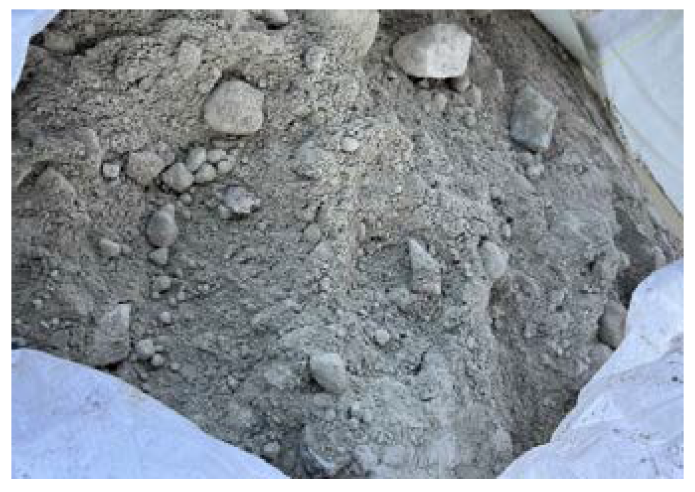
- Reducing slag: This was produced in a local electric arc furnace steelmaking plant, and its appearance is shown in Figure 1. Among them, the reducing slag coarse aggregate had a water absorption rate of 10.7%, a specific gravity of 2.70, and the fineness modulus was 5.87. The reducing slag fine-grain material had a water absorption rate of 5.29%, a specific gravity of 2.44, and a fineness modulus of 2.97. The fineness modulus (FM) of reducing slag varies greatly. The maximum value can be close to the fine aggregate of ordinary concrete, about 2.64, while the minimum value is only 0.13. The chemical composition of reducing slag is shown in Table 2.
- Bacterial solution: This contained Sporosarcina pasteurii, and its optical density (OD600) value was 1.0, as shown in Figure 2 (provided by Moji Technology Co., Ltd., Chiayi City, Taiwan).
- Cement: This was a locally produced Type I Portland cement, with a specific gravity of 3.15, and its chemical composition is shown in Table 2.
- Superplasticizer: An R-550 produced by Taiwan Sika Company was used.
2.3. Mix Proportions of the Concrete and Casting of Specimens
- (1)
- Sieve various ERSAs (stabilized and unstabilized) out of fine and coarse aggregates.
- (2)
- Put the cement and fine ERSAs into the forced single-shaft mixer and dry mix for 30 s until evenly mixed.
- (3)
- Pour water into the mixing drum and mix for 60 to 90 s to form a uniform cement mortar.
- (4)
- Pour in the coarse ERSAs and mix for 90 to 120 s to make it a uniform fresh concrete.
2.4. Test Equipment and Methods
2.4.1. Method of Test for Potential Expansion of Aggregates from Hydration Reactions
2.4.2. Determination of f-CaO in Steel Slag by EDTA Complexometric Titration
- (1)
- Take 20 g of dried aggregate and grind it to pass through a no. 100 sieve. Precisely weigh 0.200 g and add 25 mL of ethylene glycol solution, then heat for half an hour (150 ± 5 °C).
- (2)
- Use centrifugal filtration and wash thoroughly with cold water. The total filtrate is about 100 mL, and then placed in a 300 mL Erlenmeyer flask for analysis.
- (3)
- Measure about 0.3 g of vitamin C into a 300 mL Erlenmeyer flask and adjust the pH value to 12.5–13 with potassium hydroxide aqueous solution (30%). Add 5 mL of triethanolamine solution (1:1) as a masking agent, and then add calcium red indicator (about 0.1–0.2 g).
- (4)
- Finally, titrate with 0.02 M Ethylenediaminetetraacetic acid (EDTA). When the color changes from purple to blue, the endpoint of the titration is reached and the titer volume is recorded.
2.4.3. Method for Analyzing and Testing Content of f-MgO in Steel Slag
- (1)
- Take 20 g of dry aggregate and grind it to pass through the no. 100 sieve. Accurately weigh 0.200 g, add 25 mL of ethylene glycol solution and 6 mL of iodine-ethanol solution, and then heat for one hour (170 ± 5 °C).
- (2)
- Use centrifugal filtration and wash thoroughly with cold water. The total filtrate is about 60 mL and then placed in a 300 mL Erlenmeyer flask for analysis.
- (3)
- Add two or three drops of hydrochloric acid (1:1) solution into a 300 mL Erlenmeyer flask to acidify the solution. Use 6 mL of sodium thiosulfate to remove excess iodine-ethanol solution until the solution is transparent and colorless. Then, add 5 mL of triethanolamine (1:1) solution, 10 mL of ammonium chloride–ammonia buffer solution with a pH of 10, and two or three drops of K-B indicator.
- (4)
- Titrate with 0.02 mol/L EDTA standard solution until the color of the solution changes from reddish-brown to blue-green. Record the volume of EDTA solution consumed and calculate the value of free magnesium oxide.
2.4.4. pH Value Test
- (1)
- Calibrate the pH meter using two different standard solutions.
- (2)
- Take 20 ± 0.2 g of the sample and place it in a centrifuge tube. Then, add 20 mL of reagent water and shake continuously to mix it evenly.
- (3)
- Place the centrifuge tube in the centrifuge and run for one minute. Afterward, the upper aqueous phase layer can be obtained, and the pH value of the aqueous phase layer can be measured.
2.4.5. TGA/DTA Test
- (1)
- Take the reducing slag that passes the no. 100 sieve and dry it for subsequent testing.
- (2)
- Turn on the nitrogen cylinder and the instrument, place the crucible in the instrument to zero, and put 5 to 10 mg of the sample into the crucible.
- (3)
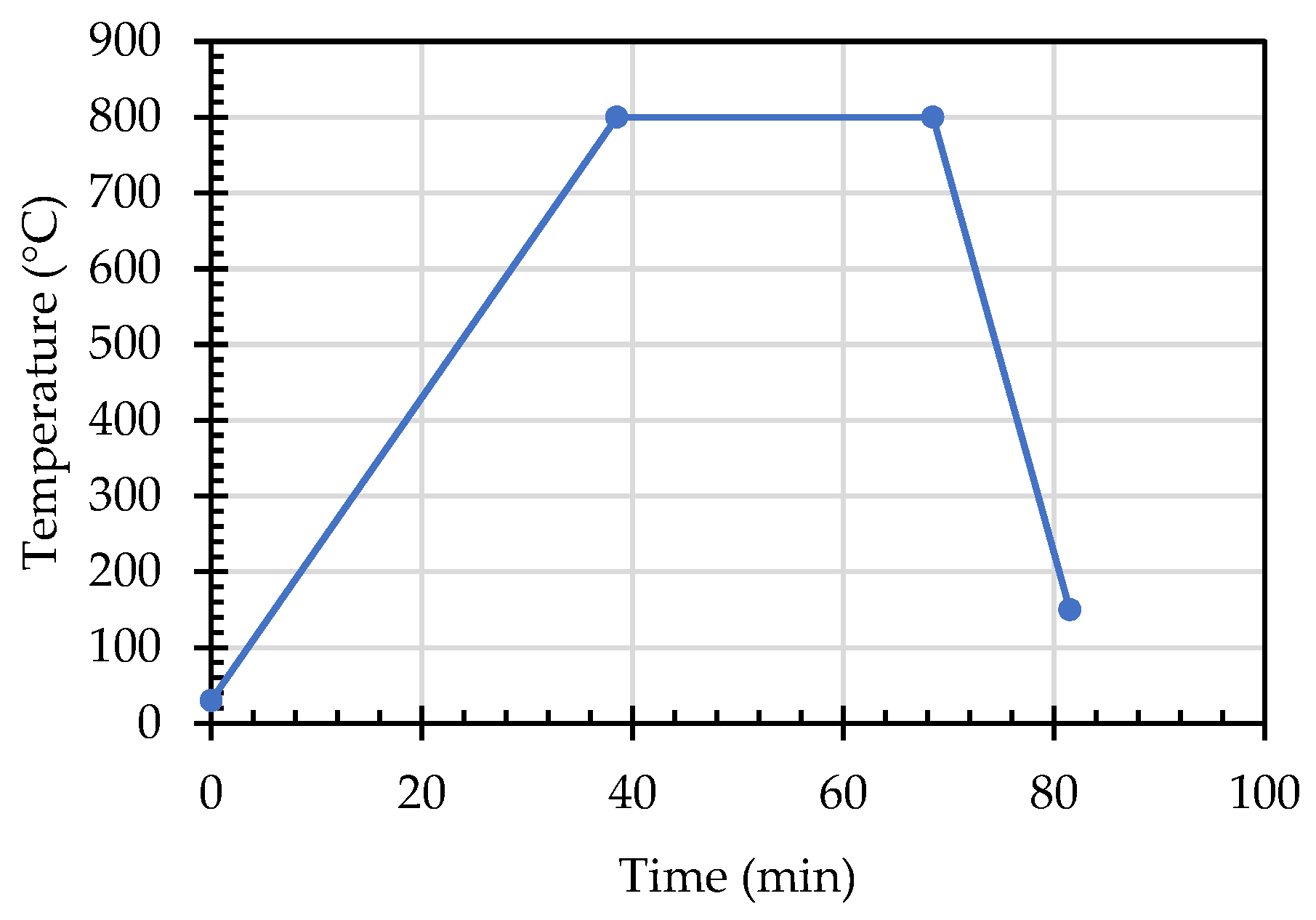
- Set the temperature parameters and increase the temperature from 30 °C to 800 °C at a rate of 20 °C/min. After rising to 800 °C, keep the temperature at 800 °C for half an hour. After that, the temperature is lowered to 150 °C at 50 °C/min to complete the test. The detailed temperature curve is shown in Figure 6.
2.4.6. SEM Observation and XRD Test
3. Results and Discussion
3.1. Results of the Potential Expansion Test of ERSAs from Hydration Reactions
3.2. Results of the Free Calcium Oxide Titration Test of ERSAs
3.3. Results of the Free Magnesium Oxide Titration Test of ERSAs
3.4. Results of the pH Value Test of ERSAs
3.5. Results of Thermogravimetric Analysis of ERSAs
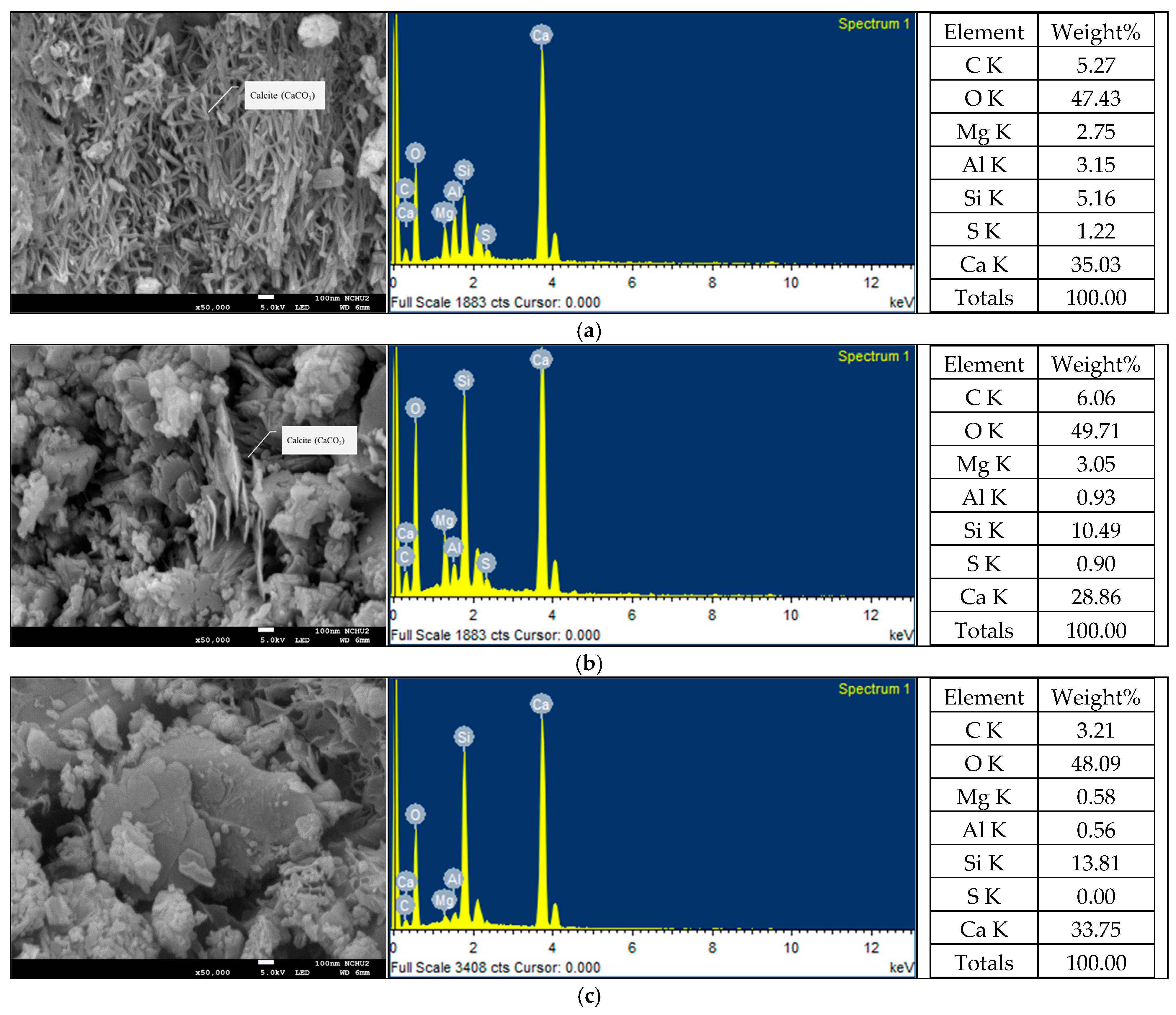
3.6. Results of SEM Observation and XRD Analysis of ERSAs
3.7. Properties of Concrete Produced with ERSAs
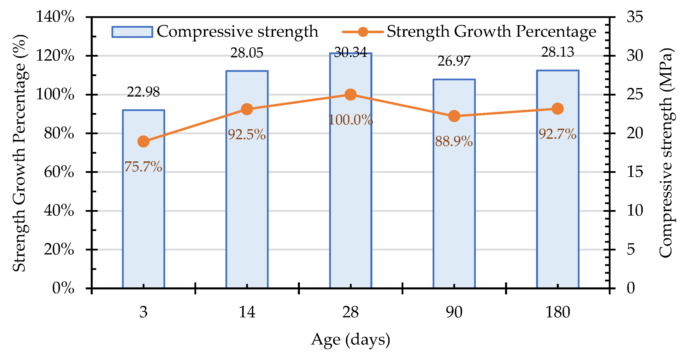
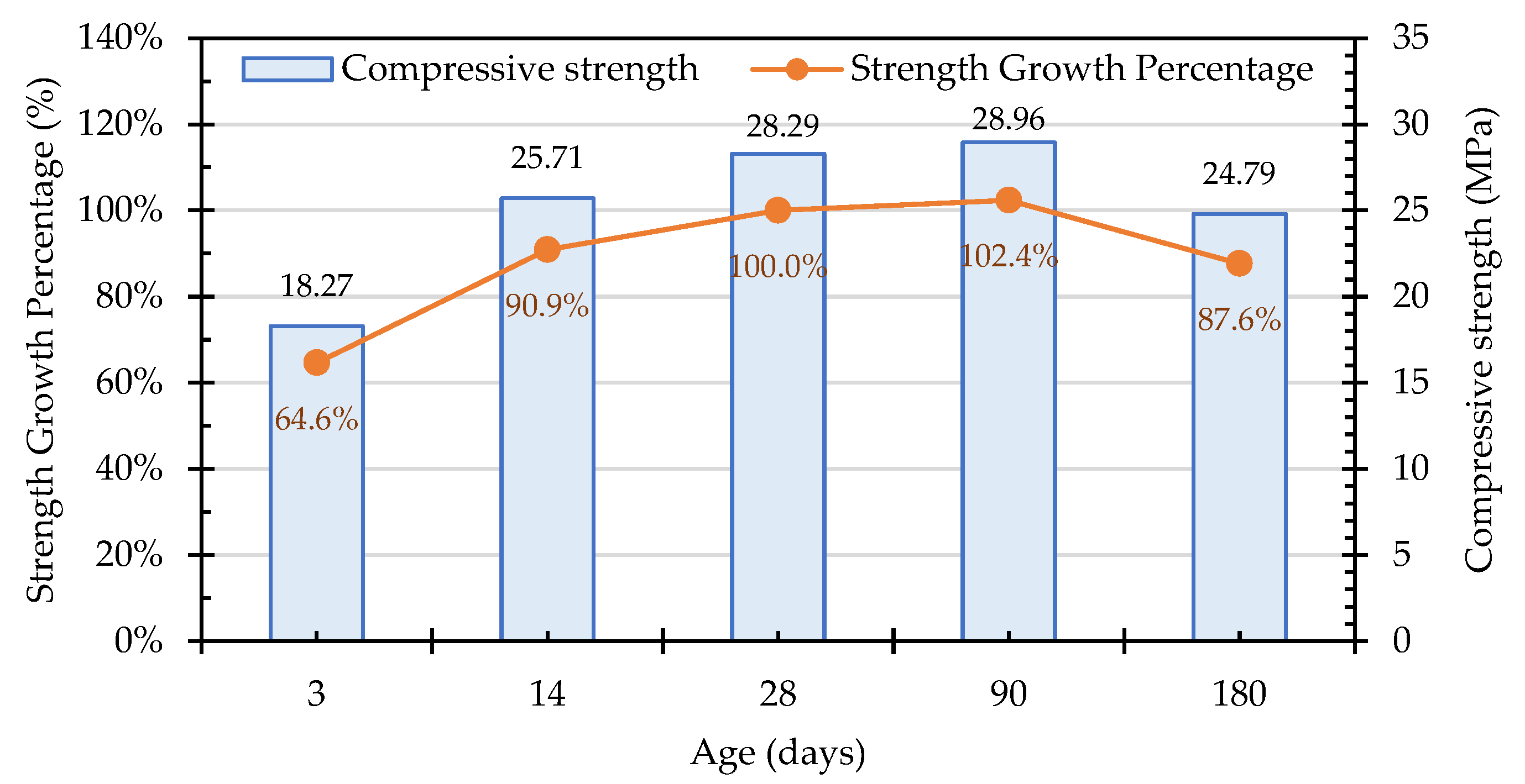
3.7.1. Compressive Strength of the Concrete Cylindrical Specimens
3.7.2. Long-Term Surface Observation of Concrete Cube Specimen
3.8. Summary and Application of Test Results
4. Conclusions
Author Contributions
Funding
Institutional Review Board Statement
Informed Consent Statement
Data Availability Statement
Acknowledgments
Conflicts of Interest
References
- Sukmak, P.; Sukmak, G.; De Silva, P.; Horpibulsuk, S.; Kassawat, S.; Suddeepong, A. The potential of industrial waste: Electric arc furnace slag (EAF) as recycled road construction materials. Constr. Build. Mater. 2023, 368, 130393. [Google Scholar] [CrossRef]
- Liang, T.; Wang, S.; Lu, C.; Jiang, N.; Long, W.; Zhang, M.; Zhang, R. Environmental impact evaluation of an iron and steel plant in China: Normalized data and direct/indirect contribution. J. Clean. Prod. 2020, 264, 121697. [Google Scholar] [CrossRef]
- Arribas, I.; Santamaría, A.; Ruiz, E.; Ortega-López, V.; Manso, J.M. Electric arc furnace slag and its use in hydraulic concrete. Constr. Build. Mater. 2015, 90, 68–79. [Google Scholar] [CrossRef]
- Qasrawi, H. The use of steel slag aggregate to enhance the mechanical properties of recycled aggregate concrete and retain the environment. Constr. Build. Mater. 2014, 54, 298–304. [Google Scholar] [CrossRef]
- Abu-Eishah, S.I.; El-Dieb, A.S.; Bedir, M.S. Performance of concrete mixtures made with electric arc furnace (EAF) steel slag aggregate produced in the Arabian Gulf region. Constr. Build. Mater. 2012, 34, 249–256. [Google Scholar] [CrossRef]
- Types of Steel Slag, Taiwan Steel & Iron Industries Association. 2018. Available online: http://steelslag.tsiia.org.tw (accessed on 11 January 2023).
- Jiang, Y.; Ling, T.C.; Shi, C.; Pan, S.Y. Characteristics of steel slags and their use in cement and concrete—A review. Resour. Conserv. Recycl. 2018, 136, 187–197. [Google Scholar] [CrossRef]
- Sobhani, J.; Komijani, S.; Shekarchi, M.; Ghazban, F. Durability of concrete mixtures containing Iranian electric arc furnace slag (EAFS) aggregates and lightweight expanded clay aggregates (LECA). Constr. Build. Mater. 2023, 400, 132597. [Google Scholar] [CrossRef]
- Sosa, I.; Thomas, C.; Polanco, J.A.; Setién, J.; Sainz-Aja, J.A.; Tamayo, P. Durability of high-performance self-compacted concrete using electric arc furnace slag aggregate and cupola slag powder. Cem. Concr. Compos. 2022, 127, 104399. [Google Scholar] [CrossRef]
- Monosi, S.; Ruello, M.L.; Sani, D. Electric arc furnace slag as natural aggregate replacement in concrete production. Cem. Concr. Compos. 2016, 66, 66–72. [Google Scholar] [CrossRef]
- Rondi, L.; Bregoli, G.; Sorlini, S.; Cominoli, L.; Collivignarelli, C.; Plizzari, G. Concrete with EAF steel slag as aggregate: A comprehensive technical and environmental characterization. Compos. B Eng. 2016, 90, 195–202. [Google Scholar] [CrossRef]
- Manso, J.M.; Polanco, J.A.; Losanez, M.; Gonzalez, J.J. Durability of concrete made with EAF slag as aggregate. Cem. Concr. Compos. 2006, 28, 528–534. [Google Scholar] [CrossRef]
- Biskri, Y.; Achoura, D.; Chelghoum, N.; Mouret, M. Mechanical and durability characteristics of High Performance Concrete containing steel slag and crystalized slag as aggregates. Constr. Build. Mater. 2017, 150, 167–178. [Google Scholar] [CrossRef]
- Maghool, F.; Arulrajah, A.; Du, Y.-J.; Horpibulsuk, S.; Chinkulkijniwat, A. Environmental impacts of utilizing waste steel slag aggregates as recycled road construction materials. Clean Technol. Environ. Policy 2017, 19, 949–958. [Google Scholar] [CrossRef]
- Nath, S.K.; Randhawa, N.S.; Kumar, S. A review on characteristics of silico-manganese slag and its utilization into construction materials. Resour. Conserv. Recycl. 2022, 176, 105946. [Google Scholar] [CrossRef]
- Wang, W.C.; Mao, Y.J. Using autoclave pulverization technology to evaluate the expansion potentiality of electric arc furnace oxidizing slag. Case Stud. Constr. Mater. 2023, 18, e01901. [Google Scholar] [CrossRef]
- Wang, Q.; Wang, D.; Zhuang, S. The soundness of steel slag with different free CaO and MgO contents. Constr. Build. Mater. 2017, 151, 138–146. [Google Scholar] [CrossRef]
- Le, D.H.; Sheen, Y.N.; Bui, Q.B. An assessment on volume stabilization of mortar with stainless steel slag sand. Constr. Build. Mater. 2017, 155, 200–208. [Google Scholar] [CrossRef]
- Teo, P.T.; Zakaria, S.K.; Salleh, S.Z.; Taib, M.A.A.; Mohd Sharif, N.; Abu Seman, A.; Mohamed, J.J.; Yusoff, M.; Yusoff, A.H.; Mohamad, M.; et al. Assessment of Electric Arc Furnace (EAF) Steel Slag Waste’s Recycling Options into Value Added Green Products: A Review. Metals 2020, 10, 1347. [Google Scholar] [CrossRef]
- Sekaran, A.; Palaniswamy, M.; Balaraju, S. A study on suitability of EAF oxidizing slag in concrete: An eco-friendly and sustainable replacement for natural coarse aggregate. Sci. World J. 2015, 2015, 972567. [Google Scholar] [CrossRef]
- Jiao, W.; Sha, A.; Liu, Z.; Jiang, W.; Hu, L.; Li, X. Utilization of steel slags to produce thermal conductive asphalt concretes for snow melting pavements. J. Clean. Prod. 2020, 261, 121197. [Google Scholar] [CrossRef]
- Pasetto, M.; Baldo, N. Experimental evaluation of high performance base course and road base asphalt concrete with electric arc furnace steel slags. J. Hazard. Mater. 2010, 181, 938–948. [Google Scholar] [CrossRef] [PubMed]
- Chen, L. Utilization of Electric Arc Furnace Oxidizing Slag as Concrete Aggregates. Ph.D. Thesis, Department of Civil Engineering, National Central University, Taoyuan City, Taiwan, 2003. [Google Scholar]
- Thomas, G.H.; Stephenson, I.M. The beta gamma dicalcium silicate phase transformation and its significance on air cooled stability. Silic. Ind. 1978, 9, 195–200. [Google Scholar]
- Pan, S.-Y.; Chiang, P.-C.; Chen, Y.-H.; Chen, C.-D.; Lin, H.-Y.; Chang, E.-E. Performance Evaluation of Aqueous Carbonation for Steelmaking Slag: Process Chemistry. Energy Procedia 2013, 37, 115–121. [Google Scholar] [CrossRef]
- Piemonti, A.; Conforti, A.; Cominoli, L.; Sorlini, S.; Luciano, A.; Plizzari, G. Use of Iron and Steel Slags in Concrete: State of the Art and Future Perspectives. Sustainability 2021, 13, 556. [Google Scholar] [CrossRef]
- Iheanyichukwu, C.G.; Umar, S.A.; Ekwueme, P.C. A Review on Self-Healing Concrete Using Bacteria. Sustain. Struct. Mater. Int. J. 2018, 1, 12–20. [Google Scholar]
- Seifan, M.; Berenjian, A. Microbially induced calcium carbonate precipitation: A widespread phenomenon in the biological world. Appl. Microbiol. Biotechnol. 2019, 103, 4693–4708. [Google Scholar] [CrossRef]
- Chen, P.Y.; McKittrick, J.; Meyers, M.A. Biological materials: Functional adaptations and bioinspired designs. Prog. Mater. Sci. 2012, 57, 1492–1704. [Google Scholar] [CrossRef]
- Frankel, R.B.; Bazylinski, D.A. Biologically induced mineralization by bacteria. Rev. Mineral. Geochem. 2003, 54, 95–114. [Google Scholar] [CrossRef]
- Mondal, S.; Ghosh, A. Biomineralization, bacterial selection and properties of microbial concrete: A review. J. Build. Eng. 2023, 73, 106695. [Google Scholar] [CrossRef]
- Weiner, S.; Dove, P. An overview of biomineralization processes and the problem of the vital effect. Rev. Mineral. Geochem. 2003, 54, 1–29. [Google Scholar] [CrossRef]
- Castro-Alonso, M.J.; Montañez-Hernandez, L.E.; Sanchez-Muñoz, M.A.; Franco, M.R.M.; Narayanasamy, R.; Balagurusamy, N. Microbially Induced Calcium Carbonate Precipitation (MICP) and Its Potential in Bioconcrete: Microbiological and Molecular Concepts. Front. Mater. 2019, 6, 126. [Google Scholar] [CrossRef]
- Dupraz, C.; Reid, R.P.; Braissant, O.; Decho, A.W.; Norman, R.S.; Visscher, P.T. Processes of carbonate precipitation in modern microbial mats. Earth Sci. Rev. 2009, 96, 141–162. [Google Scholar] [CrossRef]
- Krampitz, G.; Graser, G. Molecular mechanism of biomineralization in the formation of calcified shells. Angew. Chem. Int. Ed. Engl. 1988, 27, 145–1156. [Google Scholar] [CrossRef]
- Song, M.; Ju, T.; Meng, Y.; Han, S.; Lin, L.; Jiang, J. A review on the applications of microbially induced calcium carbonate precipitation in solid waste treatment and soil remediation. Chemosphere 2022, 290, 133229. [Google Scholar] [CrossRef] [PubMed]
- Venuleo, S.; Laloui, L.; Terzis, D.; Hueckel, T.; Hassan, M. Microbially induced calcite precipitation effect on soil thermal conductivity. Géotechnique Lett. 2016, 6, 39–44. [Google Scholar] [CrossRef]
- Achal, V.; Pan, X.L.; Zhang, D.Y. Remediation of copper-contaminated soil by Kocuria flava CR1, based on microbially induced calcite precipitation. Ecol. Eng. 2011, 37, 1601–1605. [Google Scholar] [CrossRef]
- Joshi, S.; Goyal, S.; Reddy, M.S. Influence of biogenic treatment in improving the durability properties of waste amended concrete: A review. Constr. Build. Mater. 2020, 263, 120170. [Google Scholar] [CrossRef]
- Jroundi, F.; Schiro, M.; Ruiz-Agudo, E.; Elert, K.; Martín-Sánchez, I.; González-Muñoz, M.T.; Rodriguez-Navarro, C. Protection and consolidation of stone heritage by self-inoculation with indigenous carbonatogenic bacterial communities. Nat. Commun. 2017, 8, 279. [Google Scholar] [CrossRef] [PubMed]
- Wang, R.; Jin, P.; Ding, Z.; Zhang, W. Surface modification of recycled coarse aggregate based on Microbial Induced Carbonate Precipitation. J. Clean. Prod. 2021, 328, 129537. [Google Scholar] [CrossRef]
- Chen, H.-J.; Chen, M.-C.; Tang, C.-W. Research on Improving Concrete Durability by Biomineralization Technology. Sustainability 2020, 12, 1242. [Google Scholar] [CrossRef]
- Chen, H.-J.; Chang, H.-L.; Tang, C.-W.; Yang, T.-Y. Application of Biomineralization Technology to Self-Healing of Fiber-Reinforced Lightweight Concrete after Exposure to High Temperatures. Materials 2022, 15, 7796. [Google Scholar] [CrossRef] [PubMed]
- Tang, Y.; Xu, J. Application of microbial precipitation in self-healing concrete: A review on the protection strategies for bacteria. Constr. Build. Mater. 2021, 306, 124950. [Google Scholar] [CrossRef]
- Jiang, L.; Jia, G.; Wang, Y.; Li, Z. Optimization of Sporulation and Germination Conditions of Functional Bacteria for Concrete Crack-Healing and Evaluation of their Repair Capacity. ACS Appl. Mater. Interfaces 2020, 12, 10938–10948. [Google Scholar] [CrossRef]
- Kadapure, S.A.; Kulkarni, G.S.; Prakash, K.B. A laboratory investigation on the production of sustainable bacteria-blended fly ash concrete. Arab. J. Sci. Eng. 2017, 42, 1039–1048. [Google Scholar] [CrossRef]
- Achal, V.; Pan, X.; Özyurt, N. Improved strength and durability of fly ash-amended concrete by microbial calcite precipitation. Ecol. Eng. 2011, 37, 554–559. [Google Scholar] [CrossRef]
- García-González, J.; Rodríguez-Robles, D.; Wang, J.; De Belie, N.; Del Pozo, J.M.M.; Guerra-Romero, M.I.; Juan-Valdés, A. Quality improvement of mixed and ceramic recycled aggregates by biodeposition of calcium carbonate. Constr. Build. Mater. 2017, 154, 1015–1023. [Google Scholar] [CrossRef]
- Sanna, A.; Dri, M.; Hall, M.R.; Maroto-Valer, M. Waste materials for carbon capture and storage by mineralisation (CCSM)—A UK perspective. Appl. Energy 2012, 99, 545–554. [Google Scholar] [CrossRef]
- Pan, S.-Y.; Adhikari, R.; Chen, Y.-H.; Li, P.; Chiang, P.-C. Integrated and innovative steel slag utilization for iron reclamation, green material production and CO2 fixation via accelerated carbonation. J. Clean. Prod. 2016, 137, 617–631. [Google Scholar] [CrossRef]
- Pan, S.-Y.; Chiang, P.-C.; Chen, Y.-H.; Tan, C.-S. Ex situ CO2 capture by carbonation of steelmaking slag coupled with metalworking wastewater in a rotating packed bed. Environ. Sci. Technol. 2013, 47, 3308–3315. [Google Scholar] [CrossRef]
- Zhao, L.; Wu, D.; Hu, W.; Li, J.; Zhang, Z.; Yang, F.; Wang, Z.; Ni, W. Coupling Mineralization and Product Characteristics of Steel Slag and Carbon Dioxide. Minerals 2023, 13, 795. [Google Scholar] [CrossRef]
- Qian, C.; Ren, L.; Xue, B.; Cao, T. Bio-mineralization on cement-based materials consuming CO2 from atmosphere. Constr. Build. Mater. 2016, 106, 126–132. [Google Scholar] [CrossRef]
- CNS 15311:2021; Method of Test for Potential Expansion of Aggregates from Hydration Reactions. Bureau of Standards, Metrology and Inspection, Ministry of Economic Affairs: Taipei City, Taiwan, 2021.
- Long, Y.; Lei, Y.; Zhang, Y.; Wang, S.; Han, Z.; Shi, X. Determination of free calcium oxide in steel slag by EDTA complexometric titration. Metall. Anal. 2010, 30, 65–68. [Google Scholar]
- State Intellectual Property Office of the, P.R.C. Method for Analyzing and Testing Content of Free Magnesium Oxide in Steel Slag. Patent CN101865856A, 20 October 2010. [Google Scholar]
- NIEA R208.04C; Method for Determination of Hydrogen Ion Concentration Index (pH Value) of Waste-Electrode Method. The Environmental Inspection Institute: Taipei, Taiwan, 2009.
- ASTM C39/C39M-18; Standard Test Method for Compressive Strength of Cylindrical Concrete Specimens. ASTM International: West Conshohocken, PA, USA, 2018. Available online: https://www.astm.org/Standards/C39 (accessed on 1 March 2023).
- Motz, H.; Geiseler, J. Products of steel slags an opportunity to save natural resources. Waste Manag. 2001, 21, 285–293. [Google Scholar] [CrossRef] [PubMed]
- Böhmer, S.; Gertaud, M.; Neubauer, C.; Peltoniemi, M.; Schachermayer, E.; Tesar, M.; Walter, B.; Winter, B. Aggregates Case Study. Umweltbundesamt. March 2008. Available online: https://www.scribd.com/document/95810439/Aggregates-Case-Study-Final-Report-UBA-080331 (accessed on 26 October 2022).
- Zhang, Y.; Chang, J.; He, P. Carbonation reaction of free CaO and MgO in steel slag. J. Dalian Univ. Technol. 2018, 58, 634–640. (In Chinese) [Google Scholar]
- Bouquet, E.; Leyssens, G.; Schönnenbeck, C.; Gilot, P. The decrease of carbonation efficiency of CaO along calcination–carbonation cycles: Experiments and modelling. Chem. Eng. Sci. 2009, 64, 2136–2146. [Google Scholar] [CrossRef]
- Wang, A.; Heng, M.; Mo, L.; Liu, K.; Li, Y.; Zhou, Y.; Sun, D. Research Progress of Building Materials Prepared from the Carbonized Curing Steel Slag. Mater. Rep. 2019, 33, 2939–2948. [Google Scholar]
- Zhang, K.; Tang, C.S.; Jiang, N.J.; Pan, X.H.; Liu, B.; Wang, Y.J.; Shi, B. Microbial-induced carbonate precipitation (MICP) technology: A review on the fundamentals and engineering applications. Environ. Earth Sci. 2023, 82, 229. [Google Scholar] [CrossRef] [PubMed]


| Test Variable | Variable Range and Sample Designation | |||||||||
|---|---|---|---|---|---|---|---|---|---|---|
| Particle size | 1–10 mm | 1 mm | 2 mm | 5 mm | 10 mm | |||||
| A | 1 | 2 | 5 | 10 | ||||||
| Stabilization method | Exposed to the air | Immersed in water | Immersed in a S. pasteurii bacteria solution | |||||||
| N | W | B | ||||||||
| Immersion age | 1 day | 2 days | 3 days | 4 days | ||||||
| 1D | 2D | 3D | 4D | |||||||
| Chemical Composition (%) | Reducing Slag | Cement |
|---|---|---|
| Silicon dioxide, SiO2 | 30.34 | 20.49 |
| Aluminum oxide, Al2O3 | 2.01 | 6.57 |
| Iron oxide, Fe2O3 | 2.21 | 3.27 |
| Calcium oxide, CaO | 50.49 | 62.40 |
| Magnesium oxide, MgO | 10.06 | 1.91 |
| Sulfur trioxide, SO3 | - | 2.20 |
| Free calcium oxide, f-CaO | - | 1.03 |
| Titanium dioxide, TiO2 | 0.15 | - |
| Phosphorus Pentoxide, P2O5 | 0.54 | - |
| Manganese oxide, MnO | 0.10 | - |
| Loss on ignition, LOI | 0.56 | 1.57 |
| Tricalcium silicate, C3S | - | 39.27 |
| Dicalcium silicate, C2S | - | 29.11 |
| Tricalcium aluminate, C3A | - | 11.75 |
| Tetracalcium aluminoferrite, C4AF | - | 9.96 |
| Calcium sulfate dihydrate, CSH2 | 4.73 |
| Mix Designation | Cement (kg/m3) | Water (kg/m3) | Coarse Aggregate (kg/m3) | Fine Aggregate (kg/m3) | Superplasticizer (kg/m3) | Note |
|---|---|---|---|---|---|---|
| MN | 508 | 197 | 865 | 721 | 10 | Untreated raw ERSA |
| MB | 508 | 197 | 865 | 721 | 10 | ERSA treated by immersion in a solution of S. pasteurii bacteria |
| MW | 508 | 197 | 865 | 721 | 10 | ERSA treated by immersion in a water tank |
| Sample Designation | Expansion Rate in the First 7 Days after Immersion in Water (%) | Specification Value (<0.5%) | |||||||
|---|---|---|---|---|---|---|---|---|---|
| Day 0 | Day 1 | Day 2 | Day 3 | Day 4 | Day 5 | Day 6 | Day 7 | ||
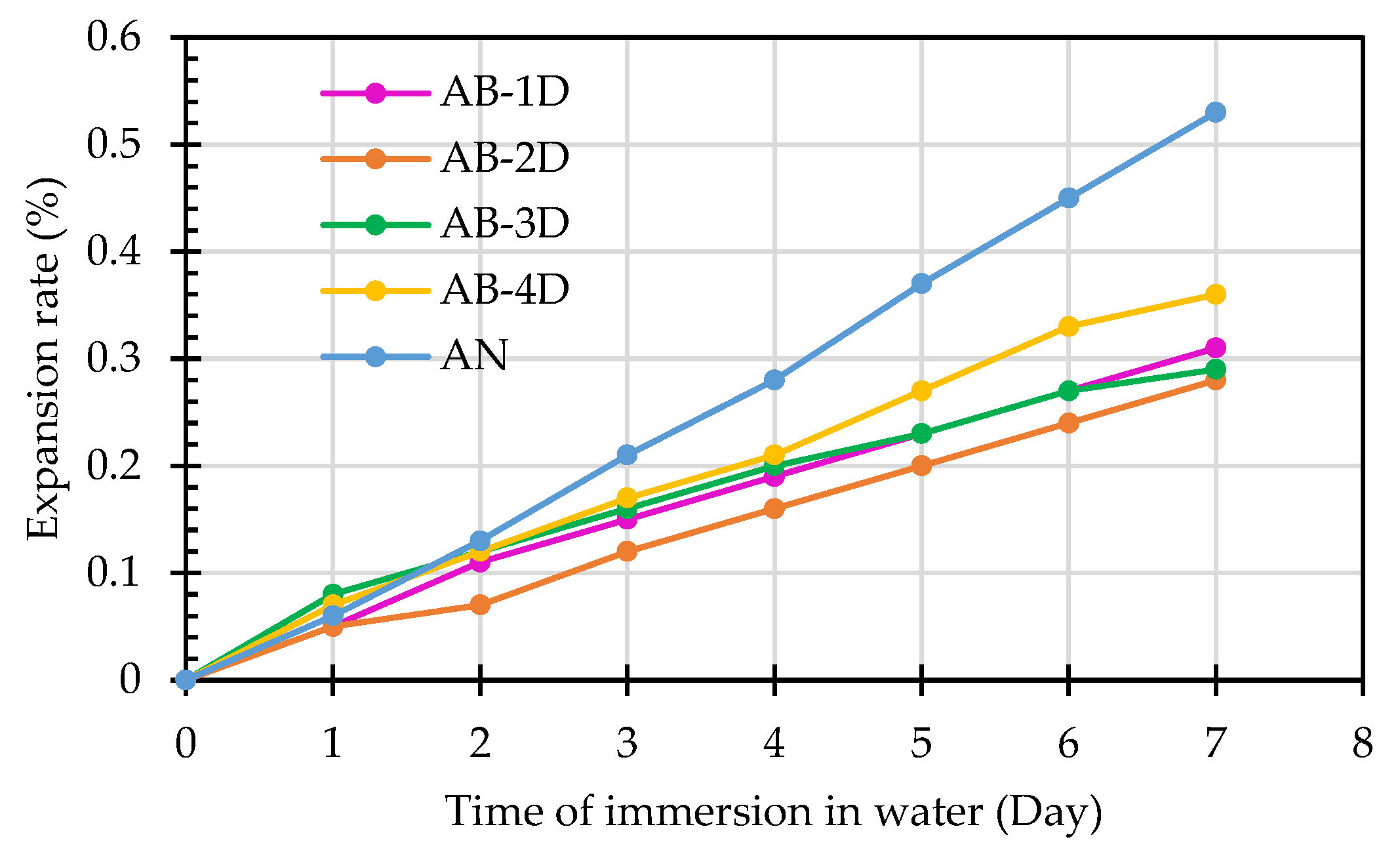
| AB-1D | 0 | 0.05 | 0.11 | 0.15 | 0.19 | 0.23 | 0.27 | 0.31 | <0.5 |
| AB-2D | 0 | 0.05 | 0.07 | 0.12 | 0.16 | 0.2 | 0.24 | 0.28 | <0.5 |
| AB-3D | 0 | 0.08 | 0.12 | 0.16 | 0.20 | 0.23 | 0.27 | 0.29 | <0.5 |
| AB-4D | 0 | 0.07 | 0.12 | 0.17 | 0.21 | 0.27 | 0.33 | 0.36 | <0.5 |
| AN | 0 | 0.06 | 0.13 | 0.21 | 0.28 | 0.37 | 0.45 | 0.53 | >0.5 |
| Sample Designation | f-CaO Content (%) | |||
|---|---|---|---|---|
| 1 mm | 2 mm | 5 mm | 10 mm | |
| N | 3.95 | 3.73 | 3.48 | 3.36 |
| B-1D | 3.50 | 3.11 | 2.86 | 2.91 |
| B-2D | 3.25 | 3.15 | 2.58 | 2.68 |
| B-3D | 3.28 | 3.09 | 2.66 | 2.49 |
| B-4D | 2.97 | 2.87 | 2.56 | 2.46 |
| W-1D | 3.86 | 3.66 | 2.84 | 2.91 |
| W-2D | 3.74 | 3.69 | 2.86 | 2.87 |
| W-3D | 3.81 | 3.75 | 2.82 | 3.00 |
| W-4D | 3.74 | 3.65 | 2.82 | 3.08 |
| Sample Designation | f-MgO Content (%) | |||
|---|---|---|---|---|
| 1 mm | 2 mm | 5 mm | 10 mm | |
| N | 7.20 | 7.06 | 7.08 | 5.83 |
| B-1D | 6.45 | 5.56 | 5.55 | 4.51 |
| B-2D | 6.34 | 5.43 | 6.08 | 5.46 |
| B-3D | 5.43 | 5.44 | 4.50 | 5.32 |
| B-4D | 5.68 | 5.46 | 4.48 | 5.36 |
| W-1D | 7.05 | 6.55 | 5.21 | 4.95 |
| W-2D | 6.97 | 6.02 | 5.81 | 4.17 |
| W-3D | 5.93 | 4.39 | 5.59 | 4.19 |
| W-4D | 5.46 | 4.28 | 5.25 | 4.36 |
| Sample Designation | pH Value | |||
|---|---|---|---|---|
| 1 mm | 2 mm | 5 mm | 10 mm | |
| N | 12.47 | 12.47 | 12.47 | 12.47 |
| B-1D | 12.19 | 11.85 | 11.34 | 10.97 |
| B-2D | 11.97 | 11.13 | 11.18 | 11.17 |
| B-3D | 11.43 | 11.20 | 11.28 | 11.19 |
| B-4D | 11.32 | 10.68 | 10.65 | 11.47 |
| W-1D | 12.17 | 12.28 | 11.95 | 11.92 |
| W-2D | 11.85 | 11.89 | 11.65 | 11.80 |
| W-3D | 11.86 | 11.68 | 11.62 | 11.90 |
| W-4D | 11.94 | 11.62 | 11.61 | 11.81 |
| Sample Designation | Weight Percentage (%) | CaCO3 Content (%) | |
|---|---|---|---|
| 650 °C | 800 °C | ||
| AN | 92.94 | 91.78 | 1.16 |
| AB1D | 92.81 | 91.34 | 1.47 |
| AB2D | 92.85 | 91.43 | 1.42 |
| AB3D | 93.2 | 91.64 | 1.56 |
| AB4D | 93.23 | 91.78 | 1.45 |
| AW1D | 93.53 | 92.53 | 1.00 |
| AW2D | 92.74 | 91.57 | 1.17 |
| AW3D | 93.22 | 92.14 | 1.08 |
| AW4D | 93.48 | 92.45 | 1.03 |
| Compound | Molecular Formula | Percentage of Ingredients (%) | ||
|---|---|---|---|---|
| Group N | Group W | Group B | ||
| Calcio olivine | CaSiO4 | 30.12 | 28.16 | 21.48 |
| Spinel | MgAl2O | 0 | 12.58 | 9.76 |
| Gehlenite | Ca2Al[AlSi2O7] | 8.44 | 8.63 | 11.16 |
| Merwinite | Ca3Mg(SiO4)2 | 29.89 | 22.61 | 27.93 |
| Katoite | Ca3Al2(SiO4)3−X(OH)4X | 5.13 | 3.63 | 2.65 |
| Brucite | Mg(OH)2 | 4.99 | 5.02 | 5.21 |
| Portlandite | Ca(OH)2 | 2.40 | 1.56 | 2.47 |
| Cuspidine | Ca4(Si2O7)(OH)2 | 11.10 | 1.65 | 1.37 |
| Periclase | MgO | 4.46 | 4.44 | 2.60 |
| Gypsum | CaSO4·2H2O | 0 | 1.38 | 1.29 |
| Fluorite | CaF2 | 0.13 | 0.15 | 0.02 |
| Grossular | Ca3Al2(SiO4)0.69(OH)9.24 | 3.34 | 5.43 | 5.51 |
| Quartz | SiO2 | 0 | 0 | 0 |
| Calcite | CaCO3 | 0 | 4.76 | 8.53 |
Disclaimer/Publisher’s Note: The statements, opinions and data contained in all publications are solely those of the individual author(s) and contributor(s) and not of MDPI and/or the editor(s). MDPI and/or the editor(s) disclaim responsibility for any injury to people or property resulting from any ideas, methods, instructions or products referred to in the content. |
© 2023 by the authors. Licensee MDPI, Basel, Switzerland. This article is an open access article distributed under the terms and conditions of the Creative Commons Attribution (CC BY) license (https://creativecommons.org/licenses/by/4.0/).
Share and Cite
Chen, H.-J.; Lin, Y.-R.; Tang, C.-W.; Hung, Y.-C. Application of Biomineralization Technology in the Stabilization of Electric Arc Furnace Reducing Slag. Appl. Sci. 2023, 13, 10435. https://doi.org/10.3390/app131810435
Chen H-J, Lin Y-R, Tang C-W, Hung Y-C. Application of Biomineralization Technology in the Stabilization of Electric Arc Furnace Reducing Slag. Applied Sciences. 2023; 13(18):10435. https://doi.org/10.3390/app131810435
Chicago/Turabian StyleChen, How-Ji, You-Ren Lin, Chao-Wei Tang, and Yi-Chun Hung. 2023. "Application of Biomineralization Technology in the Stabilization of Electric Arc Furnace Reducing Slag" Applied Sciences 13, no. 18: 10435. https://doi.org/10.3390/app131810435
APA StyleChen, H.-J., Lin, Y.-R., Tang, C.-W., & Hung, Y.-C. (2023). Application of Biomineralization Technology in the Stabilization of Electric Arc Furnace Reducing Slag. Applied Sciences, 13(18), 10435. https://doi.org/10.3390/app131810435