Article

Precision and Dimensional Stability of Bonded Joints of Carbon-Fibre-Reinforced Polymers Parts

1
Faculty of Mechanical Engineering, Brno University of Technology, Technická 2896/2, 616 69 Brno, Czech Republic
2
Faculty of Military Technology, University of Defence, Kounicova 65, 662 10 Brno, Czech Republic
3
Faculty of Management and Economics, Tomas Bata University in Zlín, Nám. T. G. Masaryka 5555, 760 01 Zlín, Czech Republic
*
Author to whom correspondence should be addressed.
Appl. Sci. 2023, 13(18), 10413; https://doi.org/10.3390/app131810413
Submission received: 7 August 2023 / Revised: 10 September 2023 / Accepted: 16 September 2023 / Published: 18 September 2023
(This article belongs to the Special Issue Recent Advances in Materials Welding and Joining Technologies)

Abstract

:
This article aims to investigate the accuracy and dimensional stability of bonded metal and CFRP (Carbon Fibre Reinforced Plastic) adherends. The motivation behind this study was to assess the suitability of CFRP for optical devices through the evaluation of precision bonding technology. A binocular was selected as a reference optical device. A technological sample was designed, with required total runout of key dimensions 0.05 mm. The sample underwent testing according to ISO 9022-1. The total runout was evaluated after production and environmental tests. Eight out of 15 samples were turned after gluing due to insufficient accuracy. None of the turned samples exceeded the total runout deviation of 0.01 mm, and the average value of the maximal deviation was 0.0041 mm. The noncalibrated samples performed significantly worse with the average value of the maximal deviation of 0.0164 mm. The measurements during the climatic tests showed that the largest deviation (on average 77.6% of the maximum achieved deviation) occurs at the first temperature loading. Subsequent temperature cycles caused lower deviations. The results highlight the significance of addressing deformations resulting from adhesive volume shrinkage-induced stress as a crucial factor in precision bonding technology.

1. Introduction

The popularity and use of fibre-reinforced composite materials have been growing year by year. The demand for composite materials tripled between 2010 and 2020 [1]. Aerospace, aviation, and energy applications have been the sectors with the largest share of both the volume produced and usage of composite materials. Currently, the COVID-19 pandemic has negatively affected certain sectors including aerospace [2] and the ground transportation industry. On the other hand, the energy sector has experienced significant growth. This growth is influenced by various factors, with one of the most significant factors being the widespread adoption of wind power in China, aligning with China’s planned path towards carbon neutrality by 2060 [2,3]. In the long term, the use of composites has grown within consumer goods and for the production of leisure equipment, with cycling, golf and fishing being the most prominent [3].
One of the reasons for using CFRP in many industries is to achieve high stiffness while maintaining low component weight [4]. Another important property of composite materials is good vibration damping, which in some applications leads to increased user comfort and reduced equipment noise. Researchers have been also dealt with hybrid composites reinforced by different types of fibres. Zouhar et al. [5] found that the application of flax fibre-reinforced hybrid composites increases damping properties compared to pure carbon-reinforced composites.
Despite the aforementioned benefits, the application of CFRPs in the production of sports optics or other optical instruments remains relatively rare. One of the primary obstacles hindering the adoption of composite materials in optical devices is the limited manufacturing precision of composite parts [6]. In some cases, limited impact resistance and the absence of plastic deformation are the main limitations [7]. In other cases, it may be necessary to consider outgassing parameters, which is currently a complex topic with limited knowledge in the context of composites [8]. However, some papers suggest that CFRP could find applications in space and cleanroom environments [9]. If these issues can be resolved, composite materials could offer numerous advantages for optical devices, namely, weight savings, better vibration damping, and improved dimensional stability. In some cases, they can also save on costs or enable the manufacturing of complex parts. Finally, composites possess a certain appeal to consumers, which, especially in the case of consumer goods, plays a crucial role in determining the product’s commercial success. In particular, carbon fibre composite materials (CFRP) are considered premium and high-tech materials widely employed in aerospace and Formula 1. Under certain conditions, usage of CFRP as a construction material can result in cost savings compared to technologies like die-casting.
Manufacturing precision and deformation elimination are key requirements for CFRP applications in optics. Kupčák et al. [6] address the evaluation of deformation during the production of a composite tubular part made by curing prepregs in an autoclave with a prototype mold. There are several strategies to eliminate deformation during composite manufacturing [10]. Changing the mold shape for compensation does not require modification of the curing process or the lay-up, but entails the production of a new mold, as it is a trial-and-error approach. Another option is to utilize a numerical model introduced by Triforia et al. [11]. Optimization of curing is another strategy to eliminate deformations. Several authors [12,13,14] have studied the relationship between spring-back during curing and dwell time at the target temperature in the autoclave, with mixed results. However, there is consensus within the scientific community that lower deformation occurs in the laminate with slower heating and cooling rates [14,15] as well as lower curing temperatures and longer curing times [12,16], albeit with increased manufacturing costs. Optimizing the contact between a part and mold also demands attention. Due to the different thermal expansions of the mold and laminate, shear stresses develop in the contact area between the part and mold, resulting in unwanted spring-back. The application of a Fluorinated Ethylene Propylene (FEP) sliding layer can reduce the shear friction and the degree of spring-back [17]. Optimizing the lay-up and prestressing the laminate during manufacturing are additional methods to enhance the discussed contact area.
The dimensional stability of composites is another important requirement for CFRP applications in many fields including optics. The fibrous structure of composite materials results in their anisotropy. Through a well-designed lay-up, mechanical properties can be customized in specific directions of the laminate, such as achieving higher stiffness in the direction under greater stress. It is even possible to attain zero or negative thermal expansion in specific directions. This has been investigated by Kelly [18] and Ito et al. [19], who describe both analytical and experimental methods. Yoon and Kim [20] studied the anisotropic behavior and thermal expansion of composite materials. They observed the relationship between fibre angle and deformation under thermal loading using ‘L-shaped’ specimens and provided a comparison between experimental measurements and an analytical model. The coefficient of thermal expansion of carbon tubes is addressed by Cordero et al. [21], primarily focusing on length expansion and the development of a measurement method.
Another critical factor to consider regarding the stability of composite materials is deformation associated with moisture absorption. Observations by Trigo [22] and Arao et al. [23] indicated that moisture absorption-induced deformation in the laminate significantly surpasses that caused by thermal loading. Arao et al.’s findings suggest that, for epoxy resins, the behavior aligns with Fick’s first law.
Due to the difficult machinability of composites, their application often requires bonding as an alternative method to reach the required shape of the final product. Composite materials based on thermosetting resin allow the use of three subtypes of bonding technology, the so-called secondary bonding, co-bonding, and co-curing. According to the research of Hasan et al. [24] and Moretti et al. [25], co-curing achieves the lowest manufacturing deformation among these bonding technologies. In the publications by Dhilipkumar and Rajesh [26] and Kim et al. [27], the strength of various types of bonded joints is compared. Both authors concluded that co-curing produces joints with the highest strength. Based on these findings, co-curing can be considered the most suitable method for joining composite components if the device design allows for it. Leone and Genna [28] investigated the increased adhesion after laser surface treatment of co-bonded samples. The laser-treated specimens achieved twice the shear strength compared to the reference specimen. Laser surface treatment has also been investigated by Fisher et al. [29] in the context of secondary-bonded specimens. Their results indicate that within secondary bonding, the abrasive-treated surface achieves the same results as the laser-treated surface.
The view on the influence of the thickness of the bonded joint on its strength has evolved and changed throughout history. Classical analytical models according to Volkersen [30] or Goland and Reissner [31] assumed that higher bonded joint thickness leads to increased strength. However, more recent research has shown that the optimum strength is achieved by a bonded joint at the thickness of 0.1 mm to 0.5 mm [32]. Da Silva et al. confirmed these findings in their experimental study of epoxy adhesives [33]. Similar results were also obtained by Zhang and Huang [34] and Shokrian et al. [35], who investigated the impact of adherend roughness in addition to epoxy adhesive layer thickness. However, some research indicates even lower values of the optimal thickness. In their study, Guo et al. [36] identified an optimal epoxy adhesive thickness of 0.03 mm and noted a significant reduction in strength when the adhesive thickness falls below 0.01 mm.
A critical phenomenon associated with bonding is the volumetric shrinkage of the adhesive during curing. This is particularly significant in precise and optical applications, where shrinkage can lead to tilt or displacement of optical elements [37] or induce stresses inside the optical elements, degrading the imaging quality of the optical instrument [38]. UV-cured adhesives are often preferred due to their nearly instantaneous curing ability, which is especially valuable in assembling micro-optical systems [39]. Broquin et al. [40] presented soldering as a possible alternative to bonding lenses with the benefit of lower residual stress values.
Müller et al. [41] addressed the bonding procedure for assemblies requiring accuracy below 1 µm. Their approach involves compensating for shrinkage effects by precisely dosing and measuring the shrinkage of a specific batch of adhesive. This is because shrinkage is affected not only by the specific batch of adhesive (owing to variations in raw materials) but also by the adhesive’s age. For successful automation, both influences must be quantified. During the experimental phase, Müller observes differences in shrinkage of up to 5% for one of the adhesives. To automate this process, accurate volumetric dosing and measuring the shrinkage before a given adhesive batch is always necessary [41]. A different approach to precision bonding is presented by Niklaus et al. [42] focusing on bonding silicon wafers. They suggested employing friction elements to prevent the wafer from sliding during adhesive curing. Through this method, they consistently achieved an accuracy of 5 μm, surpassing the 15–50 μm accuracy typically attained using commercially available add-ons.
The potential integration of carbon nanotubes (CNTs) represents a promising avenue for enhancing various aspects of composite materials. Carbon nanotubes are renowned for their exceptional mechanical properties and thermal conductivity, rendering them valuable candidates as reinforcing phases in adhesives for optical devices and precision bonding applications. Recent studies by Kiani and Pakdaman [43,44,45] as well as previous works by Kianis [46,47,48] have explored the nonlocal behavior of CNTs, demonstrating their unique mechanical characteristics. In the realm of thermal properties, CNTs exhibit remarkable thermal conductivity [49]. Additionally, CNTs have garnered attention in the field of flexible electronics and advanced packaging materials [50], showcasing their versatility in various applications. Furthermore, CNTs have been the subject of extensive research in the field of electrical conductivity within polymer nanocomposites. The work of Khromov et al. [51] underscores the potential for improved electrical properties when CNTs are integrated into composite materials. Moreover, the ultra-high optical absorption efficiency of multi-walled carbon nanotube ensembles [52] suggests their potential for use in optical instruments. In summary, the incorporation of carbon nanotubes offers a range of advantages, from enhanced mechanical properties to improved thermal and electrical conductivity, making them a promising candidate for optimizing composite materials in the domain of optical devices and precision bonding applications. These promising attributes of CNTs open up exciting opportunities for advancing the performance and functionality of such devices.
The research presented in this paper is motivated by the efforts of Meopta—optika, s.r.o. to integrate CFRP into the production of optical devices, particularly those demanding a high degree of precision and accuracy. CFRP is commonly chosen for its high stiffness, lightweight properties, low coefficient of thermal expansion (CTE), and effective damping characteristics. Nevertheless, the utilization of CFRPs in the production of sports optics and other optical instruments remains relatively uncommon. One way to integrate CFRP into the manufacturing of precise devices is through precision bonding. The optical industry frequently addresses precision bonding, primarily in the context of bonding optical components to mechanical interfaces, typically employing UV-cured adhesives [37,39,53]. However, there is a gap in the research investigating the high-precision bonding of composite structures using epoxy adhesives.
This paper builds on previous research on this topic [6,54]. The potential of CFRP in the production of optical devices was evaluated with the aim of addressing its limitations. A technological sample and testing procedure were designed in order to test the manufacturing accuracy and dimensional stability under specified environmental conditions. The aspect of dimensional stability of bonded joints in outdoor conditions is frequently underrepresented in the literature. The technology presented in this research has the potential to introduce the benefits of CFRP, including high stiffness, low weight, and a low coefficient of thermal expansion, which are well-established in other industries, to the realm of sports optics and other precision optical applications.

2. Materials and Methods

The main goal of this study was to investigate the accuracy and dimensional stability of tubular-bonded joints of metal and CFRP adherends, aiming to evaluate the suitability of CFRP for the optical devices industry. ISO 9022-1:2016 defines an optical instrument as a device whose function is based on optical phenomena [55]. This definition encompasses a wide range of devices, from specialized laboratory equipment and stargazing telescopes to simpler tools like fibre optics and magnifying glasses. For our research purposes, a reference instrument in the form of a sports optics device, primarily a binocular or spotting scope, was chosen based on several considerations. In comparison to more sophisticated optical devices, the accuracy requirements are significantly lower (although still quite high in the context of conventional engineering), increasing the likelihood of successful production. The testing conditions were established by ISO 14490-6:2014 [56] and ISO14490-7:2016 [57] for testing of optical parameters and by ISO 9022-1:2016 [55], ISO 9022-2:2015 [58], ISO 9022-3:2015 [59] and ISO 9022-8:2015 [60] for testing of mechanical properties and climatic resistance.

2.1. Material Preparation

Considering that optical instruments almost always feature rotationally symmetric lenses, the mechanical components are typically also rotationally symmetric. Therefore, winding or braiding technology may seem like a suitable choice. Parts that deviate from a cylindrical shape present challenges for winding, primarily due to fibre slippage on contoured surfaces [61] or the bridging of concave surfaces [62]. Another viable option is one of the manual laying technologies (wet laying, prepreg, infusion). These technologies offer greater flexibility in terms of manufactured shapes, but they are more labor-intensive compared to winding [63].
Despite the aforementioned limitations, winding technology was selected for the technological samples, primarily due to the availability of a wide range of commercially wound cylindrical tubes. The technological sample (Figure 1) consists of a wound quasi-isotropic CFRP tube made of [90°/0°/±30°] layers of T700 12k fibres with a length of 90 mm, an inner diameter of 50 mm, and a wall thickness of 1.5 mm. The tube was wound using a multi-axis winding machine and cured at room temperature with subsequent post-curing in an oven. The tube was supplied by a third party along with a technical datasheet, which indicated the following mechanical properties: Axial Young’s Modulus 66.6 MPa, Bending Stiffness 4.4 × 10⁹ N·mm2, and coefficient of thermal expansion in axial direction 1.2 × 10⁻⁶ K−1 No further specifications are available since the material was acquired from a third party. This tube was chosen based on matching dimensions with the requirements of the reference device and, as there were no increased stiffness requirements in this particular case, the quasi-isotropic pan-fibre composition is sufficient. The CFRP tube is bonded to anodized EN_AW-6061-T651 aluminium alloy sleeves, which represent the interface for mounting optical assemblies, such as objective and eyepiece of the Keplerian telescope. A 1 mm wide gluing gap allows for compensation of manufacturing inaccuracies of the carbon components. The precise alignment of the two aluminium alloy sleeves, in accordance with the specified tolerances defined by a total runout of the inner diameters of sleeves of 0.05 mm, is ensured by precise bonding or turning after bonding.
An assembly fixture was designed for bonding the technological sample with the required precision (Figure 2).
For the proposed technology to be a relevant alternative to CNC machining, it must achieve comparable accuracies. The total runout of the inner diameters of both sleeves was identified as a critical parameter, with a maximum allowable value set at 0.05 mm (Figure 1). These requirements must be met both post-production and following a series of mechanical and climatic tests, as detailed in the subsequent chapter.

2.2. Design of Experiments

To ensure a logical structure for the tests and experiments, it was essential to establish a methodology and schedule to be adhered to during the experiments. The processes were divided into three stages:

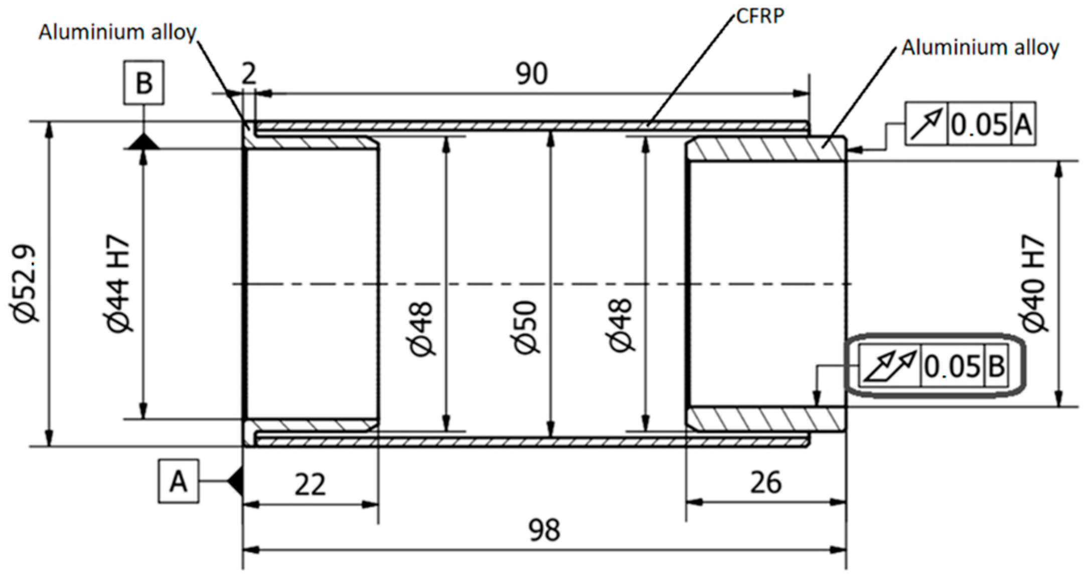
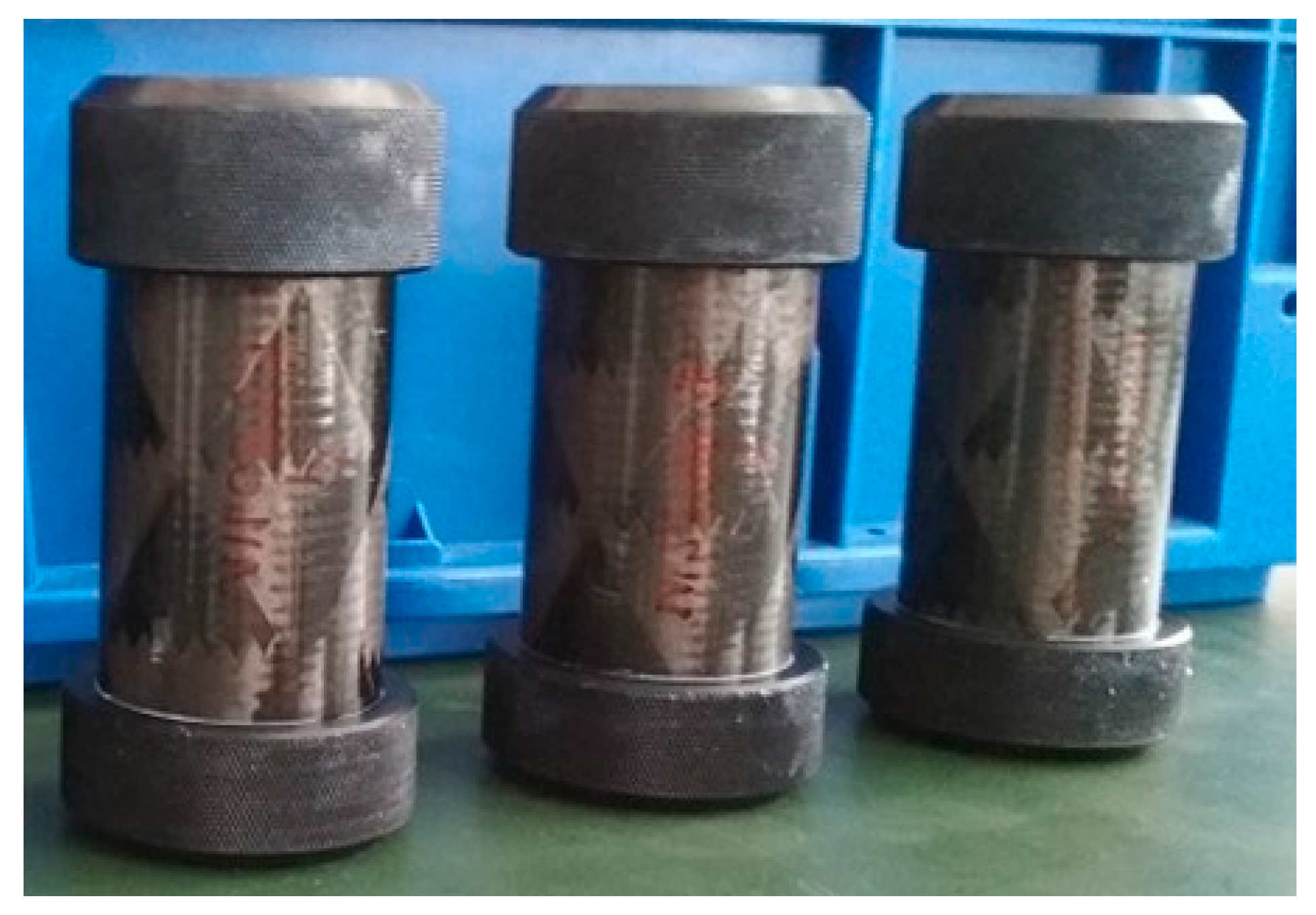
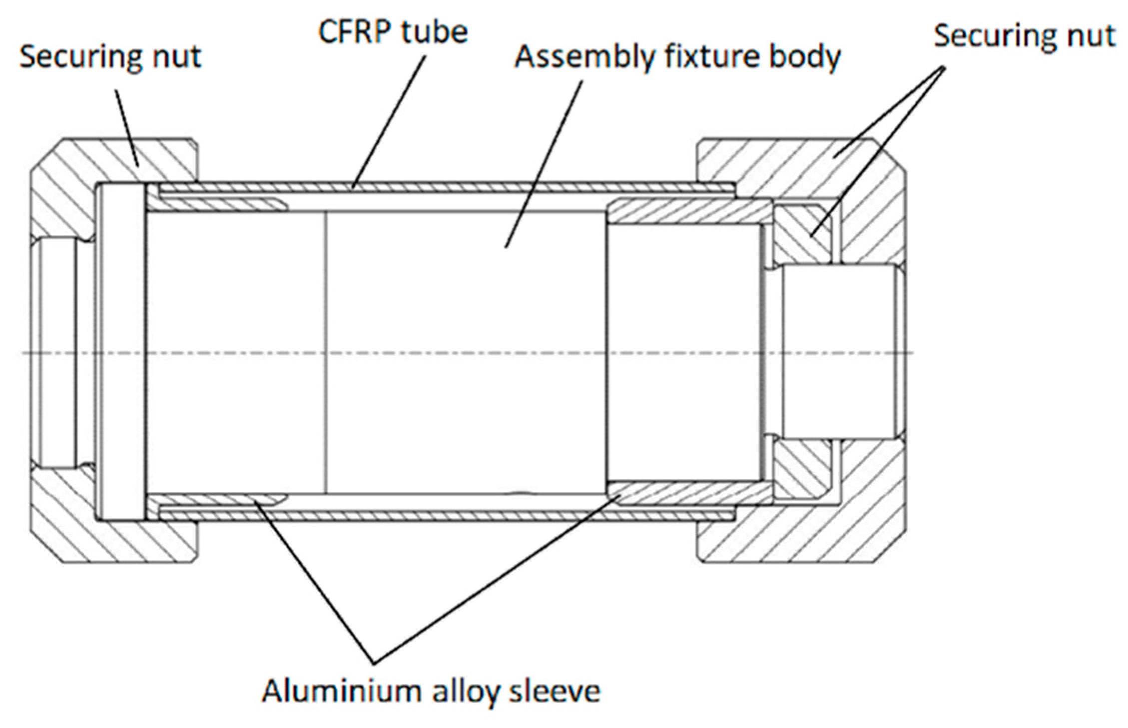
2.2.1. Stage 1 = Design and Preparation of Technological Samples

The first stage concentrated on material selection and the design of the sample and assembly fixture. Subsequently, the samples were manufactured through the turning of metal parts, shortening of carbon tubes, and the assembly of the samples using the assembly fixture.

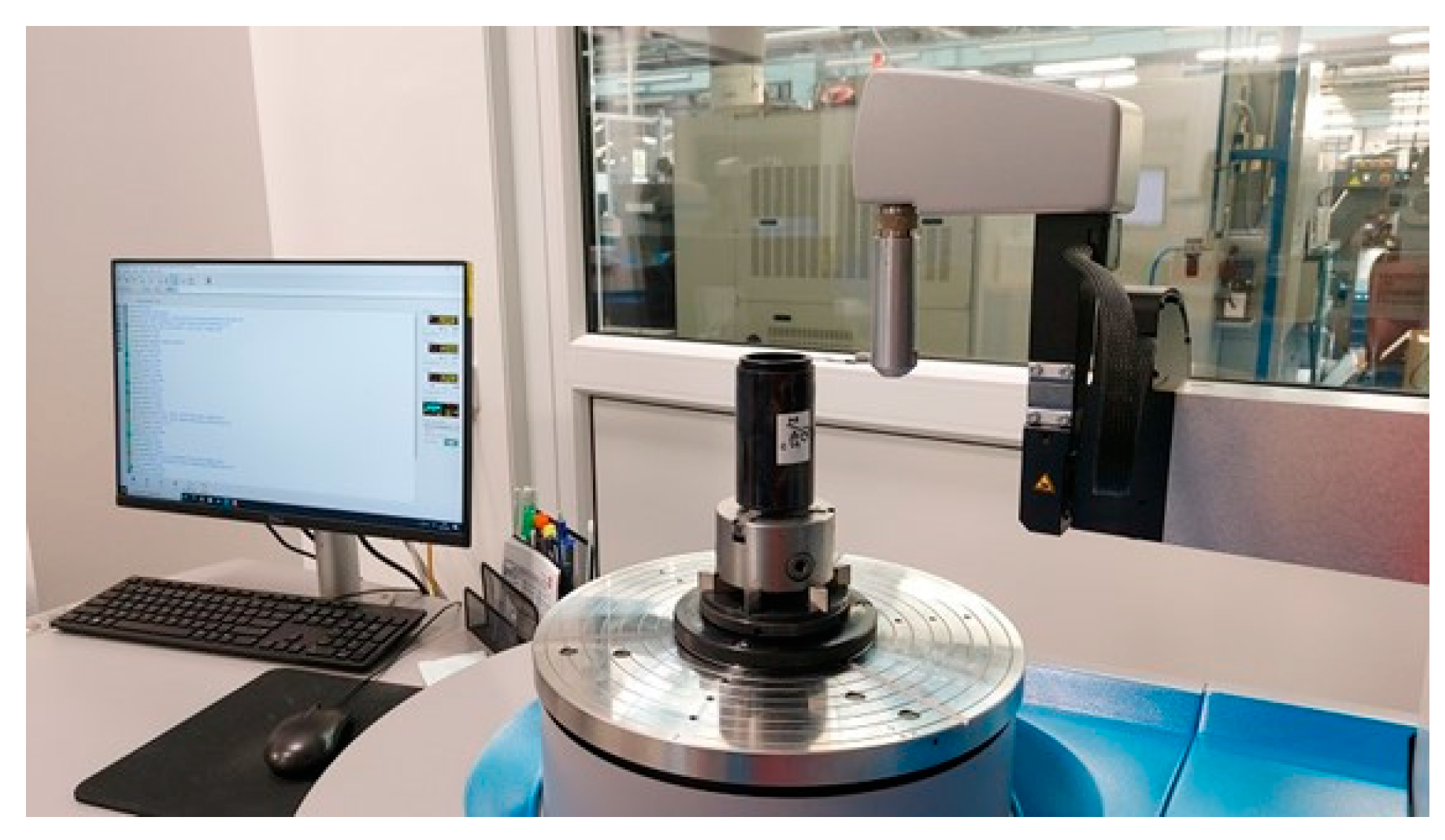
2.2.2. Stage 2 = Verification of Dimensions and Geometric Tolerances

The inspection of the pieces was carried out using CMM Zeiss Contura G2, Formline Roundscan 555, and a set of OK/NOK gauges.

2.2.3. Stage 3 = Verification of the Dimensional Stability of a Bonded Joint under Operating Conditions

During the final stage, samples with unsatisfactory tolerances were rectified by turning and tested again according to the methodology of stage 2. Subsequently, climatic resistance tests based on ISO 9022-2:2015 were conducted using the climatic chamber Vötsch VT3 7030 S2.
Initially, the technological sample was placed into a climatic chamber tempered to +70 ± 2 °C and held at this temperature for 16 h. Then, the same process was repeated at temperatures of −40 ± 3 °C. The final climatic resistance test was focused on thermal shock testing, during which the technological sample was subjected to thermal shocks at temperatures of −25 °C/+40 °C in 6 cycles and change time not longer than 20 s.
Following all climatic resistance tests, the dimensions and geometric tolerances of the samples were verified again using the same equipment and measurement methods as in stage 2. The final set of mechanical resistance tests, as per ISO 9022-3:2015, included a shock test, a bump test utilizing TIRAshock 4110, and a sinusoidal vibration test employing a Derritron TW 6000 device. Subsequent to the completion of all mechanical resistance tests, the dimensions and geometric tolerances of the samples were verified according to the methodology of stage 2.

2.3. Selection of Adhesives

Epoxy adhesives are widely used in composite materials [7]. Specific adhesives were selected according to the following criteria:
  • the selected adhesive is suitable for bonding metals and thermoplastics;
  • it has high environmental resistance (−40 °C to +70 °C);
  • and low shrinkage (although most manufacturers do not specify this parameter).
Finally, 5 adhesives that fulfilled all the above-mentioned criteria were selected and used in our experiments, more specifically, 3 types of 3M Scotch-WeldTM Epoxy Adhesive (DP110 Gray, DP125 Gray, and DP190 Gray), Gurit Spabond 340 LV HT (further just Spabond 340 LV), and Stachema Eprosin Flex (further just Eprosin Flex). Their technical properties are presented in Table 1.

3. Results

According to the prescribed methodology and schedule, 15 samples were produced (Figure 3). Their purpose was to evaluate the manufacturing precision and dimensional stability of the bonded joint under environmental conditions specified in Section 2.2.

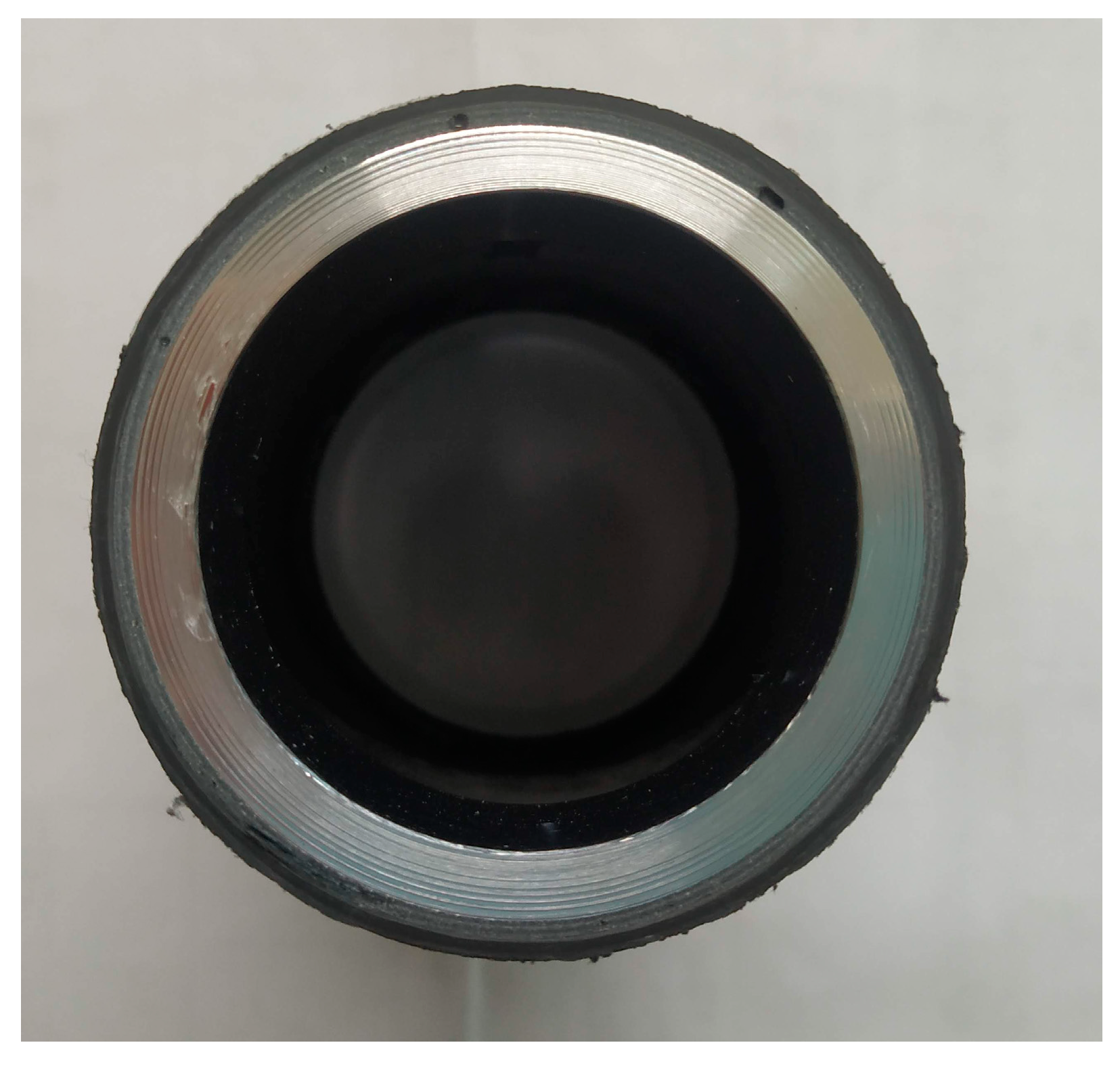
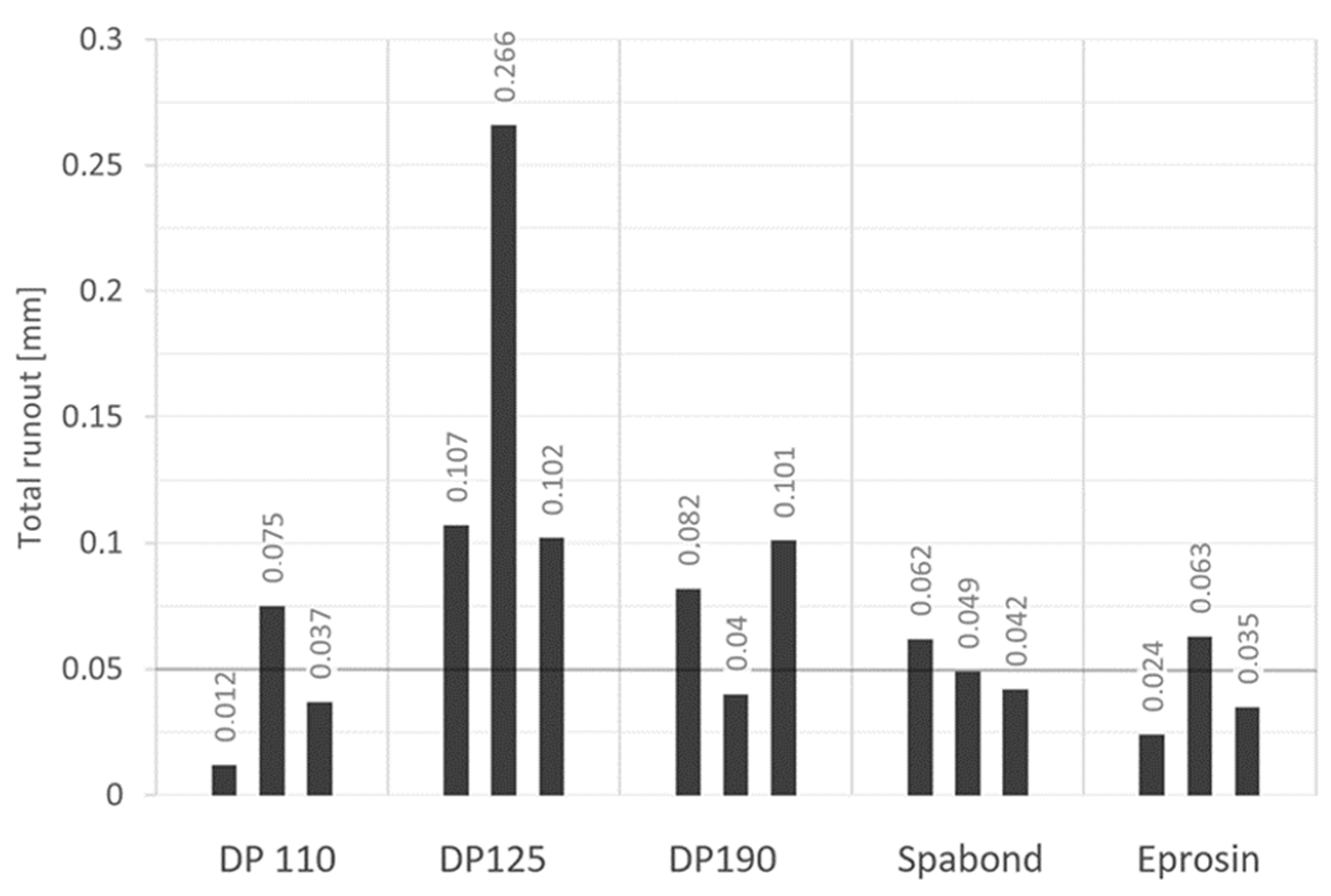
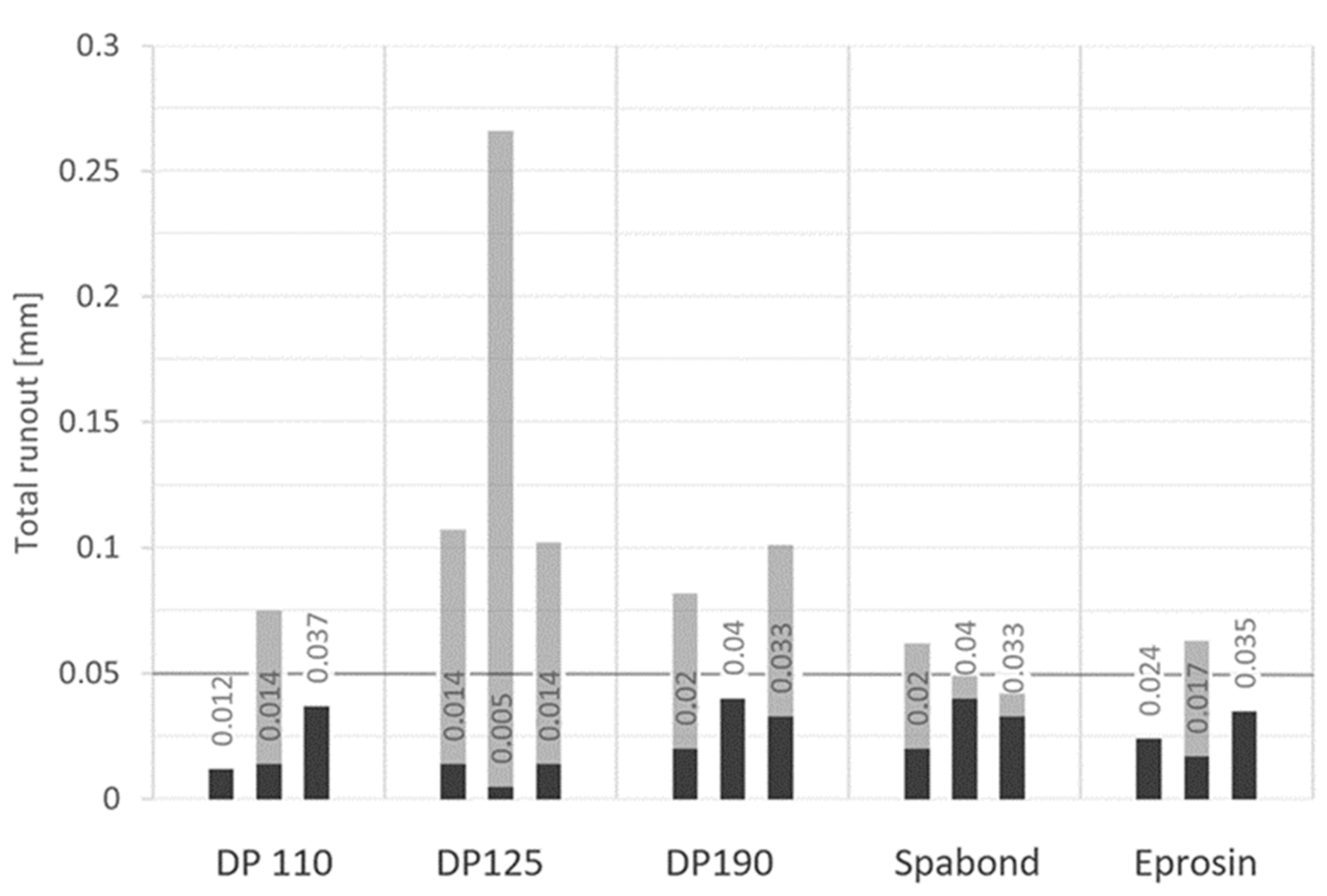
3.1. Verification of Manufacturing Accuracy after Precision Bonding

The primary evaluation parameter for manufacturing precision was the total runout of Ø40 relative to base B (Figure 1). Sample inspection was conducted using a Zeiss Contura G2 3D CMM and a Formline Roundscan 555 (Figure 4). The measured values are presented in the graph (Figure 5). Out of the 15 samples, seven (46.6%) achieved the required accuracy of 0.05 mm.
Table 2 illustrates that none of the adhesives resulted in a 100% success rate for the samples. Notably, adhesive DP 125 did not produce a single sample with the required precision, which could initially suggest unsatisfactory performance when compared to the other adhesive types. However, it is important to consider the small statistical sample size, which may introduce deviations due to factors such as incorrect assembly (particularly evident in the high deviation for DP 125 samples) or suboptimal adhesive applications resulting in the presence of bubbles/voids in the bonded joint. When examining the average deviations, DP 125 and DP 190 adhesives exhibit lower performance, while DP 110, Eprosin, and Spabond achieve comparable results.
The technological suitability of the adhesives is an important factor as well, determined by parameters such as processing time, viscosity, mixability, and the tendency to leak out of the bonded joint. These parameters are detailed in Table 3.
Based on the conducted experiments and measurements, the following conclusions can be drawn:
  • A total of 46.6% of the samples exhibited a total runout deviation below 0.05 mm, meeting the specified requirements and thus were considered satisfactory.
  • The noncompliant samples likely experienced stress generation during the curing process, leading to a radial shift after removal from the assembly fixture. Potential stress sources include excessive adhesive shrinkage and uneven filling of the adhesive joint, which may be further verified through a CT scan.
  • Among the tested adhesives, DP 110, Eprosin, and Spabond yielded the most favorable results and appear to be suitable choices for these bonding applications.
  • Enhancing the accuracy of the assembly fixture and the precision of metal counterparts could lead to increased sample accuracy, consequently improving the guaranteed geometric precision.

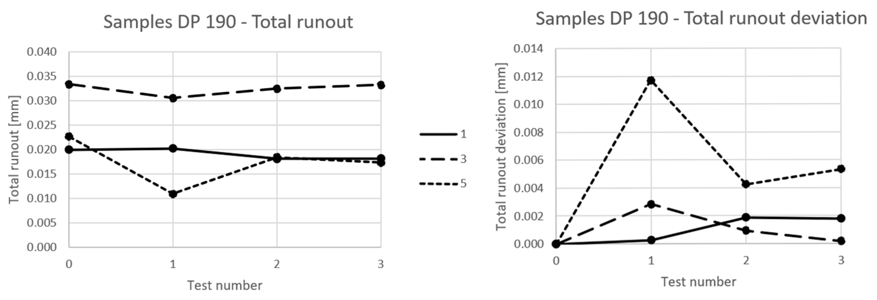
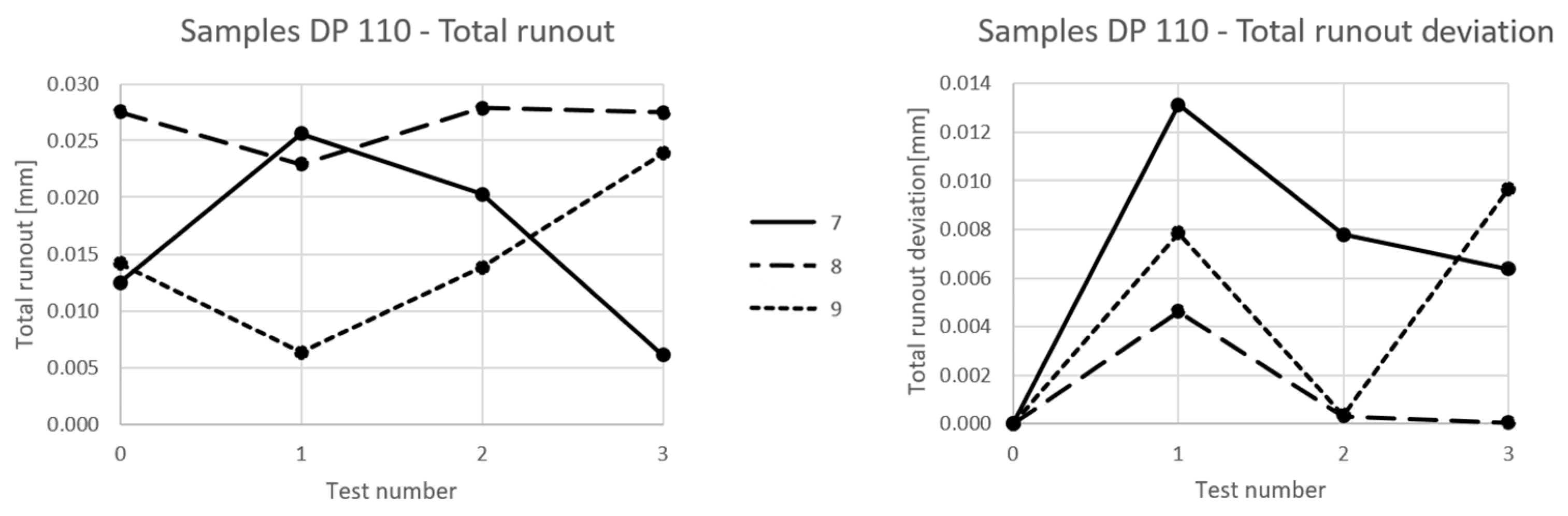
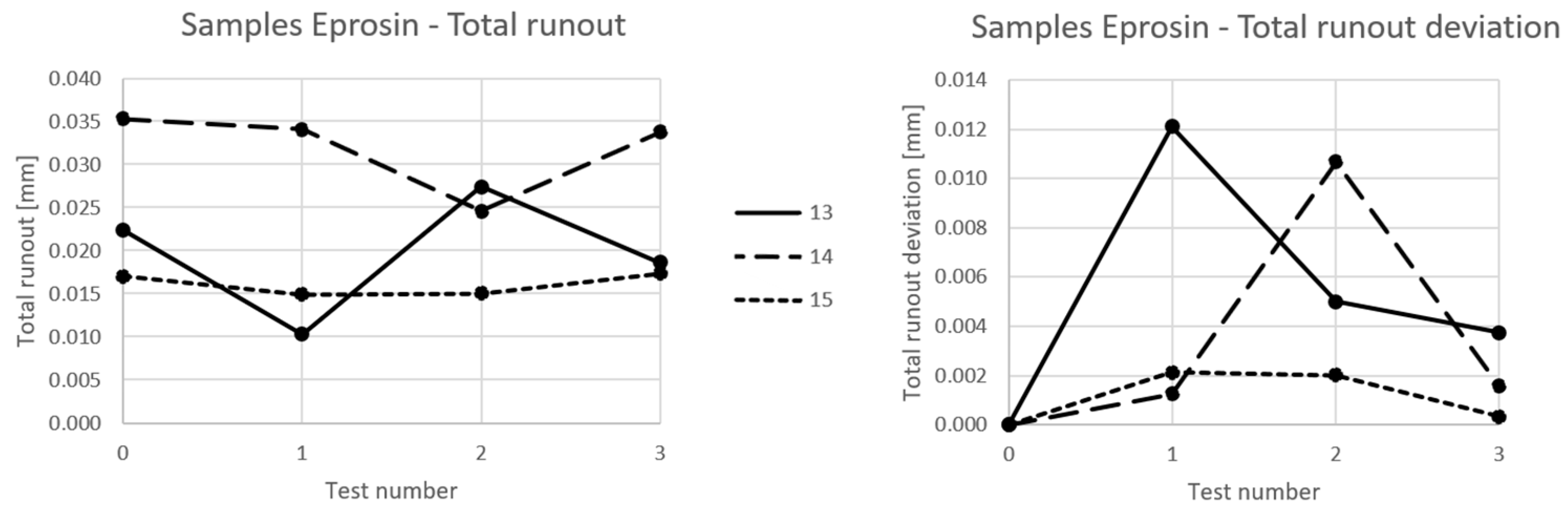
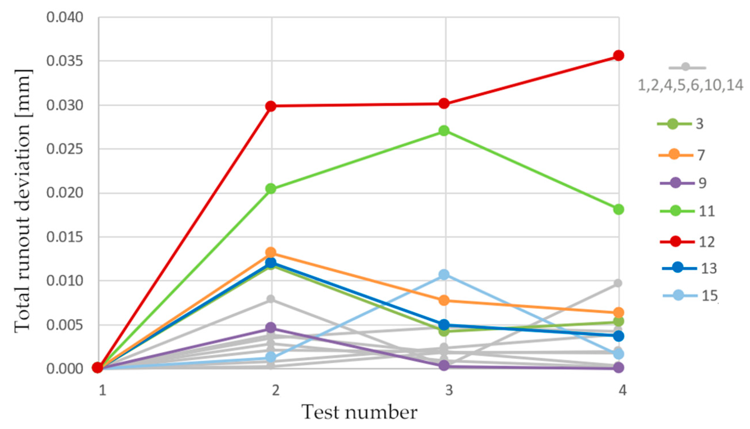
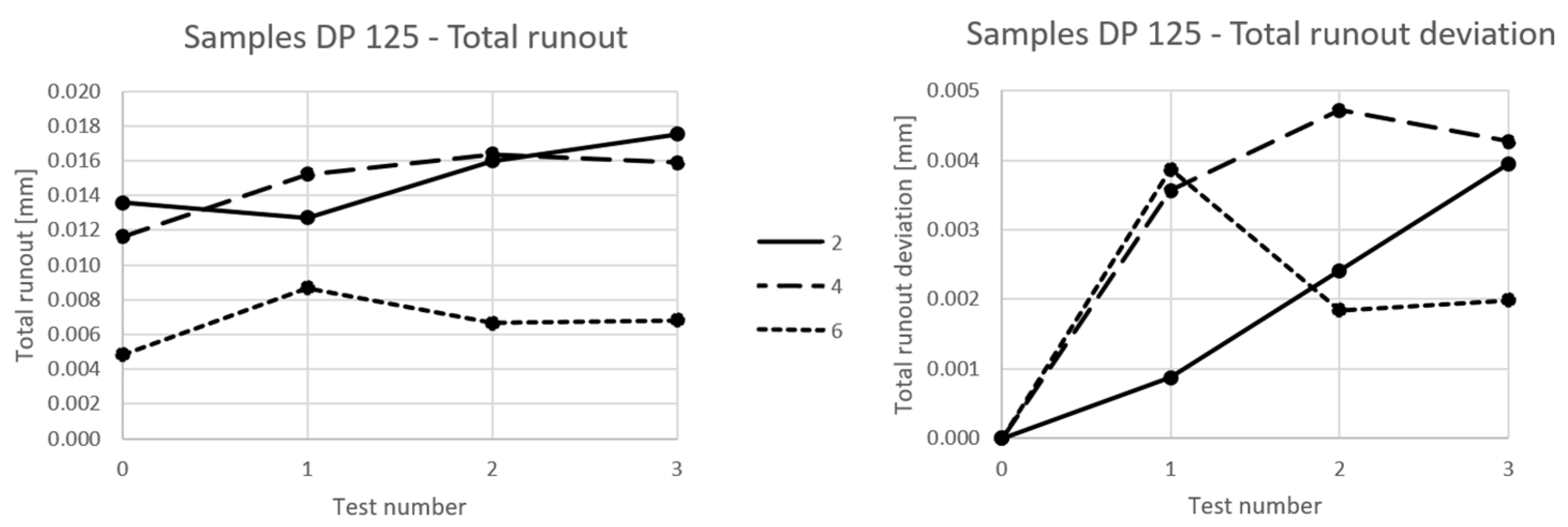
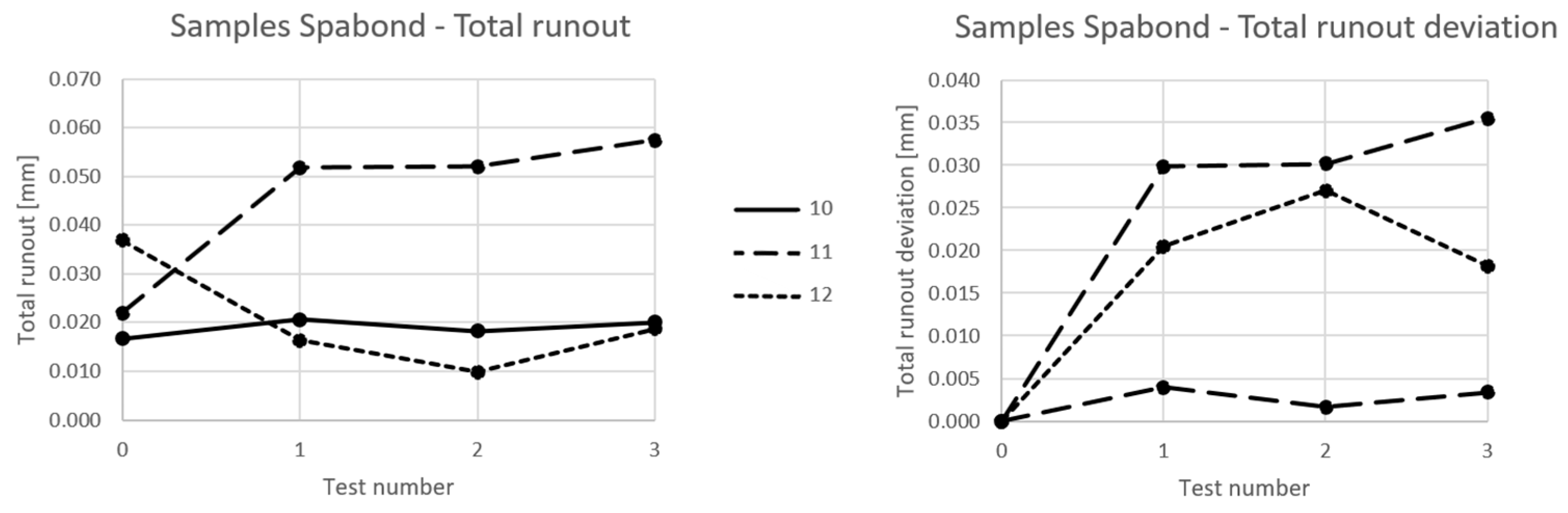
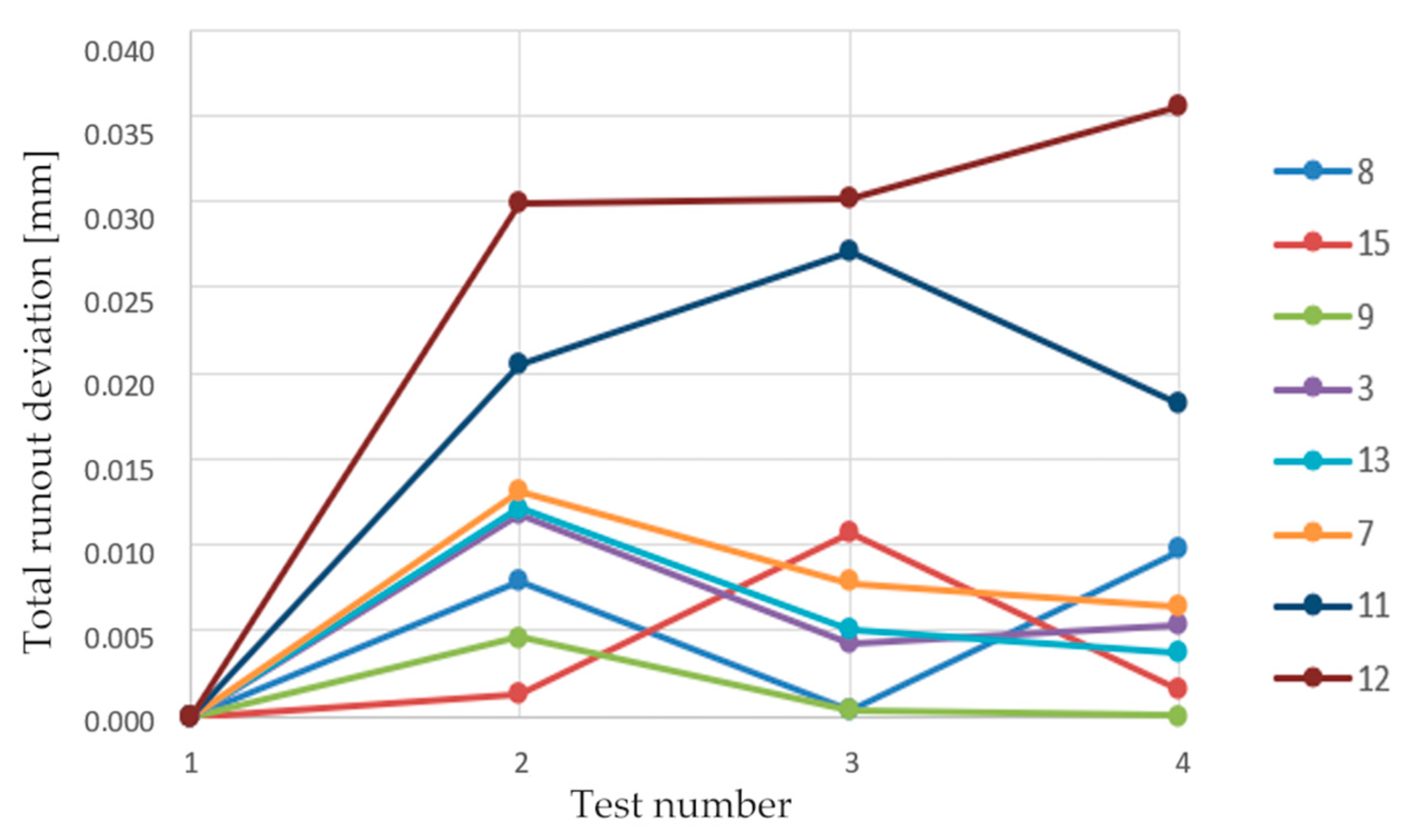
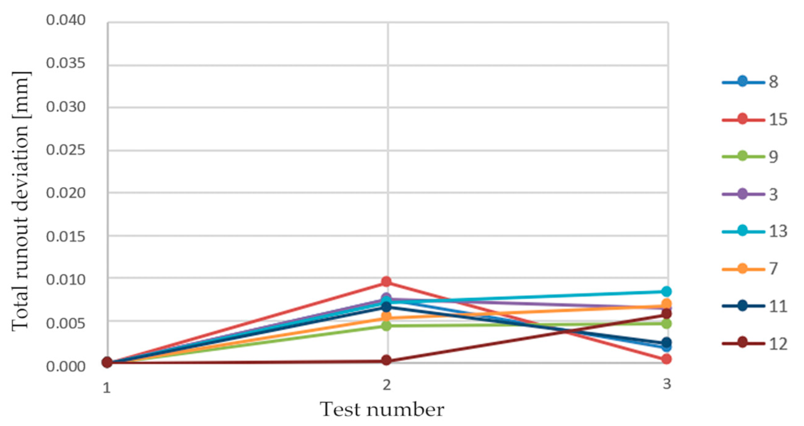
3.2. Verification of Dimensional Stability of Bonded Joint

When assessing the feasibility of using composite materials in optical instruments, it is crucial to consider not only manufacturing precision but also the dimensional stability during the instrument’s operation. The aim of stage three of the study is to experimentally verify the dimensional stability of bonded joints during environmental testing based on the standards ISO 9022-1:2016, [55] ISO 9022-2:2015, [58] ISO 9022-3:2015 [59] and ISO 9022-8:2015 [60].
The noncompliant samples from the previous stage required calibration by turning to achieve the necessary accuracy before undergoing environmental testing. As shown in Figure 6, the total runout of all the samples met the required standards after calibration, as indicated by the highlighted portion of the columns in comparison to the previous values in lighter color.
Following the calibration of the samples, two cycles of thermal resistance tests and one cycle of mechanical resistance tests were carried out. The measured total runout values after each test are detailed in Table 4. Throughout and after the tests, there were no observed issues related to adhesion, cohesion, or visible damage.
Figure 7, Figure 8, Figure 9, Figure 10 and Figure 11 display the changes in total runout and its deviations after each of the environmental tests, as the data indicate in Table 4. Despite the discrete nature of the data, line charts were employed to facilitate a clearer representation of the results.
The initial assessment of the data indicates that 14 out of 15 samples (93.3%) meet the required total runout tolerance of 0.05 after passing all environmental test cycles. However, the development of the change in total runout that occurred during the tests is more significant, especially the fact that eight of the 15 samples (53.3%) did not exceed the total runout of 0.005 mm throughout environmental tests. This suggests that under certain conditions, this type of the bonded joint exhibits sufficient stability for application in sports optics. It is important to highlight that five out of the 15 samples (33.3% of the total samples, 71% of the noncalibrated samples) exceeded the deviation of 0.01 mm at least once during the environmental tests, with the largest deviation measured at 0.036 mm for sample 12. This underscores the heterogeneous behavior of the sample set, where some samples meet the stability requirements, while others exceed them significantly.

4. Discussion

4.1. Finding 1: Calibration Leading to an Increase in Dimensional Stability

The graph in Figure 12 illustrates the relationship between the machining (calibration) of the samples and the total runout deviation during the tests. It provides insights into how the machining of the samples influenced their performance during the tests in a positive way.
None of the eight samples that underwent calibration turning exceeded a total runout deviation of 0.01 mm. For seven out of eight of the calibrated samples (87.5%), the deviation did not even exceed 0.005 mm. In contrast, among the noncalibrated samples, a significant portion, six out of seven (85%), exceeded the 0.01 mm tolerance at least once during environmental testing, and two of them (28.5%) exceeded the deviation of 0.025 mm at least once during testing. This suggests that calibration turning significantly improved the stability and precision of the samples. The validity of this statement can be quantitatively assessed by comparing the average maximum deviation value ¯ m a x of calibrated and noncalibrated samples and the average value of the final deviation ¯ e n d of calibrated and noncalibrated samples (Table 5).
Based on these findings, it can be deduced that during calibration/machining, a significant portion of the shrinkage stress in the bonded joint is released. This stress causes a deformation resulting in a change in the total runout of the unmachined samples when subjected to thermal loading. Stress relaxation during machining can result from either mechanical or thermal loading. Therefore, it is essential to account for shrinkage stress after the adhesive has completely cured in future research aimed at addressing this issue. Additionally, the creeping behavior of the adhesives employed may be another significant factor affecting precision and dimensional stability.
This finding is to some extent in line with other researchers’ observations. Müller et al. [41] also investigated the impact of shrinkage on high-precision bonded assemblies. Their approach involves automated active compensation for misalignment, very accurate volumetric dosing of the adhesive, and frequent measurements of the shrinkage of the adhesive. While replicating their approach was not possible in this research, the findings by Müllers et al. regarding changes in volumetric shrinkage of up to 5% within batches further underscore the complexity of this issue.
Lafeber et al. [69] have researched adhesive bonding with high accuracy as well. Their findings suggest that increasing the bonded gap size leads to greater adhesive shrinkage. Conversely, minimizing the gap size enhances the strength of the bonded joint [32,33]. Achieving minimal gap sizes requires optimizing the manufacturing precision of CFRP parts.
Some adhesives, like Spabond™ 340 LV HT used in this study, may either require or benefit from curing at elevated temperatures. While it can cure at 21 °C for 28 days, accelerating the curing process by applying higher temperatures can result in increased tensile strength, a higher glass transition temperature, and reduced volumetric shrinkage [67]. Yu et al. study a similar phenomenon with nonconductive adhesives. Their research indicated that higher cure temperatures led to reduced shrinkage, likely due to the expansion of materials at elevated temperatures [37].
In plastic injection molding, glass beads can be added to enhance mechanical properties or reduce shrinkage. Kovacs et al. [38] delt with this phenomenon as they study three types of deformation during the cooling of PA6 specimens. In his experiments, increasing the glass bead content led to a decrease in shrinkage. Perhaps a similar approach could be used to improve the manufacturing accuracy of precision bonded joints. Another additive under consideration is carbon nanotubes (CNTs), which have gained popularity for various applications. In bonded joints, they are used in research to improve mechanical properties [70,71] or to benefit from the changes in piezo resistance that CNTs bring to monitor stresses in the bonded joint [72].

4.2. Finding 2: Significant Effect of Initial Temperature Load

From the data presented in Figure 13 and Figure 14, it is evident that for noncalibrated samples, the most significant deformation occurs during the initial temperature loading. Figure 13 illustrates the evolution of total runout deviation for noncalibrated samples and encompasses all four rounds of measurement. Meanwhile, Figure 14 presents the same data, excluding the first round of measurement, and considers the state after the initial temperature loading as the starting point.
The results affirm that the majority of deformation takes place during the initial temperature cycle. This observation is quantified in Table 6, which indicates that, on average, 77.6% of the maximum deflection value occurred after the first temperature test. In contrast, the final step, which involved mechanical testing, resulted in an average deflection increase of 31.4% (calculated relative to the previous condition). These findings highlight the most significant changes occurring during the initial thermal loading. Consequently, incorporating a technological heat treatment during the manufacturing process could enhance the dimensional stability of the product.

4.3. Following Research and Emerging Technologies

Based on the findings presented in this study, further investigation will be conducted as part of the experimental research. This subsequent phase will involve interferometric measurement of stresses induced by volumetric shrinkage, and throughout the calibration and thermal testing. This will help determine which technological configuration yields the most stable results. Furthermore, an analysis will be conducted to examine the correlation between bonded joint homogeneity and stability using CT Scan technology. Figure 15 displays a cross-sectional view of a sample obtained by removing a portion of the sample through machining, revealing the presence of voids within the sample.
Recent developments in engineering sciences opened promising opportunities for future research and innovation. Emerging methodologies such as “deep learning” and “artificial neural networks” have introduced novel avenues for the analysis of complex systems, offering comprehensive insights into a wide array of structural responses. In the context of the study on the precision and dimensional stability of bonded joints in CFRP parts, it is essential to acknowledge the potential influence of these advanced techniques.
One of the significant aspects of these emerging research areas is the identification of inherent biases in deep convolutional neural network models, as outlined by Dai et al. [73]. Recognizing and addressing these biases are of paramount importance in the broader landscape of research, as they can significantly impact analysis and result interpretation. Although Mallikarjuna et al. [74] focused on a different domain, their work presents a multigradient-direction-based deep-learning model for disease identification. This concept of employing deep learning for pattern recognition holds potential in assessing the homogeneity and recognizing defects of bonded joints. Additionally, Du et al. [75] introduced a probabilistic time series forecasting approach with deep nonlinear state space models, which could have many applications in manufacturing technologies in general. Lastly, Fan et al. [76] introduce an intelligent vehicle lateral control system based on a radial basis function neural network sliding mode controller. While their application differs from ours, it underscores the potential of neural network-based control strategies in general, which could be useful in any automation.
In recent years, there has been a growing body of research utilizing deep-learning techniques for the analysis of (CFRP). Valença et al. [77] presented a comprehensive benchmarking study that assesses strain in CFRP laminates using computer vision. Their work delves into the distinction between traditional machine learning and deep-learning approaches, offering valuable insights into potential methodologies for future investigations in our field. Wei et al. [78] proposed a deep-learning method for the segmentation of impact damage in CFRP specimens inspected via infrared thermography. This application aligns with research on precision bonding technology, particularly in the context of defect and deformation detection. By recognizing the significance of these emerging approaches in engineering sciences, we can draw attention to them as valuable subjects for future research. These references serve as a foundation for exploring innovative avenues in the field of precision bonding technology for CFRP parts.

5. Conclusions

This paper deals with the use of composite materials for optical devices. The effort to implement these materials in the optical industry is based on the technical practice of Meopta—optika, s.r.o. Composite materials can provide improved damping and dimensional stability parameters compared to metallic structural materials. A great advantage of composites is also the possibility of fine tuning the mechanical properties in individual laminate directions. As a result, it is possible to achieve higher stiffness in the loaded direction and significantly lower weight compared to conventional metallic materials.
As part of the research phase, a binocular was selected as a reference device, serving as a model for designing the technological sample in the experimental segment. Based on the requirements placed on the binoculars, a methodology for the environmental testing of the technological sample was developed. The necessary level of accuracy was determined by considering the tolerances typically attainable in the production of optical instruments through traditional manufacturing methods.
The technological samples were composed of a CFRP tube bonded to aluminum alloy sleeves using an assembly fixture. A total of 46.6% of the samples achieved the required precision after bonding. The failed samples were calibrated by turning. Throughout the stability tests of the bonded joint, which encompassed two climate resistance tests and one mechanical resistance test, the following observations were made:
  • Among the calibrated samples, 87.5% (seven out of eight) did not exceed a deviation of 0.005 mm.
  • In the case of noncalibrated samples, 85% (six out of seven) exceeded a deviation of 0.01 mm at least once during the environmental tests. This difference is likely attributed to the shrinkage stress in the bonded joint, which was partially released during the turning process in the calibrated samples.
  • The most significant deformation occurred during the initial temperature load. Noncalibrated samples reached an average of 77.6% of the maximum deviation after the first temperature load. This suggests that after the first temperature cycle, the bonded joint stabilizes considerably, possibly due to the stress relief mentioned earlier.
Based on these findings, it is clear that further research should focus on understanding and mitigating deformations in the bonded joint. Shrinkage stress appears to be a significant factor contributing to these deformations, and the results suggest that it can be effectively addressed through post-bonding machining or heat treatment. These technological steps may need to be integrated into the production process. If future research can develop a manufacturing technology that consistently and reliably achieves the required precision in CFRP bonding, it is highly likely that this technology will find practical applications in the production of precision CFRP devices.

Author Contributions

Conceptualization, R.K. and J.Z.; methodology, R.K. and J.Z.; software, J.V. and L.G.; validation, R.K., J.Z. and D.H.; formal analysis, D.H.; investigation, R.K. and D.H.; resources, R.K. and D.H.; data curation, J.V. and L.G.; writing—original draft preparation, R.K. and D.H.; writing—review and editing, R.K. and D.H.; visualization, R.K. and L.G.; supervision, J.Z.; project administration, J.Z.; funding acquisition, J.Z. and L.G. All authors have read and agreed to the published version of the manuscript.

Funding

This work has been supported by the project No. FV 22–10 funded by The Ministry of Education, Youth and Sports (MEYS, MŠMT in Czech) support. The part of the presented work was supported by the Project for the Development of the Organ-ization “VAROPS (DZRO VAROPS) Military autonomous and robotic assets” by the Ministry of Defence of Czech Republic.

Institutional Review Board Statement

Not applicable.

Informed Consent Statement

Not applicable.

Data Availability Statement

Not applicable.

Conflicts of Interest

The authors declare no conflict of interest.

References

  1. Qiao, Y.; Fring, L.; Pallaka, M.; Simmons, K. A review of the fabrication methods and mechanical behavior of continuous thermoplastic polymer fiber–thermoplastic polymer matrix composites. Polym. Compos. 2023, 44, 694–733. [Google Scholar] [CrossRef]
  2. Pierrejean, E.; Glowacz, F. JEC Observer: Current Trends in the Global Composites Industry 2021–2026; JEC Group, Estin & Co.: Paris, France, 2022; ISBN 9782490263042. Available online: https://www.nxtbook.fr/newpress/jeccomposites/jec-observer-trends-industry-2021-2026/index.php#/p/56 (accessed on 20 July 2022).
  3. Zhang, J.; Chevali, V.; Wang, H.; Wang, C. Current status of carbon fibre and carbon fibre composites recycling. Compos. Part B Eng. 2020, 193, 108053. [Google Scholar] [CrossRef]
  4. Gregor, L.; Zouhar, J.; Kupčák, R.; Varhaník, M.; Sedlák, J. Design and stiffness distribution analysis of motorcycle swingarm made of carbon fiber composites. In Proceedings of the 2020 11th International Symposium on Image and Signal Processing and Analysis (ISPA), Dubrovnik, Croatia, 23–25 September 2019; pp. 162–165. [Google Scholar] [CrossRef]
  5. Zouhar, J.; Slaný, M.; Sedlák, J.; Joska, Z.; Pokorný, Z.; Barényi, I.; Majerík, J.; Fiala, Z. Application of Carbon–Flax Hybrid Composite in High Performance Electric Personal Watercraft. Polymers 2022, 14, 1765. [Google Scholar] [CrossRef]
  6. Kupčák, R.; Zouhar, J. Application of composite materials in sports optics. Manuf. Technol. 2020, 20, 200–209. [Google Scholar] [CrossRef]
  7. Camanho, P.; Hallett, S. (Eds.) Composite Joints and Connections: Principles, Modelling and Testing; Woodhead Publishing: Sawston, UK, 2016; ISBN 9781845699901. [Google Scholar]
  8. Pastore, R.; Delfini, A.; Albano, M.; Vricella, A.; Marchetti, M.; Santoni, F.; Piergentili, F. Outgassing effect in polymeric composites exposed to space environment thermal-vacuum conditions. Acta Astronaut. 2020, 170, 466–471. [Google Scholar] [CrossRef]
  9. Sun, B.; Xue, C.; Shang, W.; An, M.; Zhao, H.; Zhang, H. The performance characterization of carbon fiber–reinforced plastic for space applications. J. Reinf. Plast. Compos. 2023, 42, 844–853. [Google Scholar] [CrossRef]
  10. Liu, Z.; Zheng, X.; Fan, W.; Wang, F.; Ahmed, S.; Yan, L. An alternative method to reduce process-induced deformation of CFRP by introducing prestresses. Chin. J. Aeronaut. 2022, 35, 314–323. [Google Scholar] [CrossRef]
  11. Traiforos, N.; Turner, T.; Runeberg, P.; Fernass, D.; Chronopoulos, D.; Glock, F.; Schuhmacher, G.; Hartung, D. A simulation framework for predicting process-induced distortions for precise manufacturing of aerospace thermoset composites. Compos. Struct. 2021, 275, 114465. [Google Scholar] [CrossRef]
  12. White, S.R.; Hahn, H.T. Cure Cycle Optimization for the Reduction of Processing-Induced Residual Stresses in Composite Materials. J. Compos. Mater. 1993, 27, 1352–1378. [Google Scholar] [CrossRef]
  13. Fernlund, G.; Rahman, N.; Courdji, R.; Bresslauer, M.; Poursartip, A.; Willden, K.; Nelson, K. Experimental and numerical study of the effect of cure cycle, tool surface, geometry, and lay-up on the dimensional fidelity of autoclave-processed composite parts. Compos. Part A Appl. Sci. Manuf. 2002, 33, 341–351. [Google Scholar] [CrossRef]
  14. Jung, W.-K.; Chu, W.-S.; Ahn, S.-H.; Won, M.-S. Measurement and Compensation of Spring-back of a Hybrid Composite Beam. J. Compos. Mater. 2007, 41, 851–864. [Google Scholar] [CrossRef]
  15. Kravchenko, O.; Kravchenko, S.; Pipes, R. Cure history dependence of residual deformation in a thermosetting laminate. Compos. Part A Appl. Sci. Manuf. 2017, 99, 186–197. [Google Scholar] [CrossRef]
  16. Olivier, P.; El Sawi, I. Designing curing conditions in order to analyse the influence of process-induced stresses upon some mechanical properties of carbon / epoxy laminates at constant Tg and degree of cure. Int. J. Mater. Form. 2010, 3, 1373–1389. [Google Scholar] [CrossRef]
  17. Albert, C. Spring-in and warpage of angled composite laminates. Compos. Sci. Technol. 2002, 62, 1895–1912. [Google Scholar] [CrossRef]
  18. Kelly, A. Controlling thermal expansion to obtain negative expansivity using laminated composites. Compos. Sci. Technol. 2005, 65, 47–59. [Google Scholar] [CrossRef]
  19. Ito, T.; Suganuma, T.; Wakashima, K. A micromechanics-based analysis for tailoring glass-fiber-reinforced thermoplastic laminates with near-zero coefficients of thermal expansion. Compos. Sci. Technol. 2000, 60, 1851–1861. [Google Scholar] [CrossRef]
  20. Yoon, K.; Kim, J.-S. Thermal Deformations of Carbon/Epoxy Laminates for Temperature Variation; ICCM: Paris, France, 1999. [Google Scholar]
  21. Cordero, J.; Heinrich, T.; Schuldt, T.; Gohlke, M.; Lucarelli, S.; Weise, D.; Johann, U.; Braxmaier, C. Interferometry based high-precision dilatometry for dimensional characterization of highly stable materials. Meas. Sci. Technol. 2009, 20, 095301. [Google Scholar] [CrossRef]
  22. Trigo, J. Dimensional stability characterisation of carbon fiber with epoxy and cyanate ester resin laminates due to moisture absorption. In Spacecraft Structures, Materials and Mechanical Engineering, Proceedings of the Conference held by ESA, CNES and DARA in Noordwijk, 27–29 March 1996; European Space Agency (ESA): Paris, France, 1996. [Google Scholar]
  23. Arao, Y.; Fukui, T.; Niwa, T.; Kawada, H. Dimensional stability of epoxy-based and cyanate-based carbon fiber-reinforced plastics. J. Compos. Mater. 2015, 49, 1483–1492. [Google Scholar] [CrossRef]
  24. Hasan, Z.; Rader, J.; Olson, A.; Turpin, D.; Onge, R.S.; Amback, J. Design, analysis and fabrication of thick co-cured wing structures. Compos. Part B Eng. 2019, 177, 107335. [Google Scholar] [CrossRef]
  25. Moretti, L.; Olivier, P.; Castanié, B.; Bernhart, G. Experimental study and in-situ FBG monitoring of process-induced strains during autoclave co-curing, co-bonding and secondary bonding of composite laminates. Compos. Part A Appl. Sci. Manuf. 2021, 142, 106224. [Google Scholar] [CrossRef]
  26. Dhilipkumar, T.; Rajesh, M. Enhancing strength and stiffness of composite joint through co-cure technique. Compos. Commun. 2021, 27, 100878. [Google Scholar] [CrossRef]
  27. Kim, G.-H.; Choi, J.-H.; Kweon, J.-H. Manufacture and performance evaluation of the composite hat-stiffened panel. Compos. Struct. 2010, 92, 2276–2284. [Google Scholar] [CrossRef]
  28. Leone, C.; Genna, S. Effects of surface laser treatment on direct co-bonding strength of CFRP laminates. Compos. Structures 2018, 194, 240–251. [Google Scholar] [CrossRef]
  29. Fischer, F.; Krelig, S.; Jäschke, P.; Frauenhofer, M.; Kracht, D.; Dilger, K. Laser Surface Pre-Treatment of CFRP for Adhesive Bonding in Consideration of the Absorption Behaviour. J. Adhes. 2012, 88, 350–363. [Google Scholar] [CrossRef]
  30. Velkersen, O. Die nietkraftoerteilung in zubeanspruchten nietverbindungen mit konstanten loschonquerschnitten. Luftfahrtforschung 1938, 41–47. [Google Scholar]
  31. Goland, M.; Reissner, E. The Stresses in Cemented Joints. J. Appl. Mech. 1944, 11, 17–27. [Google Scholar] [CrossRef]
  32. Gleich, D.; van Tooren, M.; Beukers, A. Analysis and evaluation of bondline thickness effects on failure load in adhesively bonded structures. J. Adhes. Sci. Technol. 2001, 15, 1091–1101. [Google Scholar] [CrossRef]
  33. Da Silva, L.; Rodrigues, T.; Figueiredo, M.; de Moura, M.; Chousal, J. Effect of Adhesive Type and Thickness on the Lap Shear Strength. J. Adhes. 2006, 82, 1091–1115. [Google Scholar] [CrossRef]
  34. Zhang, D.; Huang, Y. Influence of surface roughness and bondline thickness on the bonding performance of epoxy adhesive joints on mild steel substrates. Prog. Organ. Coat. 2021, 153, 106135. [Google Scholar] [CrossRef]
  35. Shokrian, M.; Shelesh-Nezhad, K.; Najjar, R. The effects of Al surface treatment, adhesive thickness and microcapsule inclusion on the shear strength of bonded joints. Int. J. Adhes. Adhes. 2019, 89, 139–147. [Google Scholar] [CrossRef]
  36. Guo, L.; Liu, J.; Xia, H.; Li, X.; Zhang, X.; Yang, H.; Yang, Y. Effects of loading rate, temperature, and thickness on the tensile strength of precision adhesive joints. Polym. Test. 2022, 109, 107528. [Google Scholar] [CrossRef]
  37. Yu, H.; Mhaisalkar, S.G.; Wong, E.H. Effect of temperature on the cure shrinkage measurement of non-conductive adhesives for flip chip interconnects. J. Mater. Res. 2005, 20, 1324–1329. [Google Scholar] [CrossRef]
  38. Kovács, J.G.; Solymossy, B. Effect of glass bead content and diameter on shrinkage and warpage of injection-molded PA6. Polym. Eng. Sci. 2009, 49, 2218–2224. [Google Scholar] [CrossRef]
  39. Müller, T.; Venu, V.K.; Haag, S.; Zontar, D.; Sauer, S.; Wenzel, C.; Brecher, C. Strategies for precision adhesive bonding of micro-optical systems. Proc. SPIE 2015, 93460, 93460E. [Google Scholar] [CrossRef]
  40. Ribes, P.; Koechlin, C.; Burkhardt, T.; Hornaff, M.; Burkhardt, D.; Kamm, A.; Gramens, S.; Beckert, E.; Fiault, G.; Eberhardt, R.; et al. High-precision opto-mechanical lens system for space applications assembled by innovative local soldering technique. Proc. SPIE 2016, 9750, 97501k. [Google Scholar] [CrossRef]
  41. Müller, T.; Haag, S.; Bastuck, T.; Gisler, T.; Moser, H.; Uusimaa, P.; Axt, C.; Brecher, C. Robust adhesive precision bonding in automated assembly cells. Proc. SPIE 2014, 8965, 89650Y. [Google Scholar] [CrossRef]
  42. Niklaus, F.; Enoksson, P.; Kälvesten, E.; Stemme, G. A method to maintain wafer alignment precision during adhesive wafer bonding. Sens. Actuators A Phys. 2003, 107, 273–278. [Google Scholar] [CrossRef]
  43. Kiani, K.; Pakdaman, H. Bilaterally nonlocal dynamics of layer-by-layer assembly of double-walled carbon nanotubes accounting for intertube rigorous van der Waals forces. Eur. J. Mech.-A/Solids 2020, 80, 103876. [Google Scholar] [CrossRef]
  44. Kiani, K.; Pakdaman, H. On the nonlocality of bilateral vibrations of single-layered membranes from vertically aligned double-walled carbon nanotubes. Phys. Scr. 2020, 95, 035221. [Google Scholar] [CrossRef]
  45. Kiani, K.; Pakdaman, H. Nonlocal vibrations and potential instability of monolayers from double-walled carbon nanotubes subjected to temperature gradients. Int. J. Mech. Sci. 2018, 144, 576–599. [Google Scholar] [CrossRef]
  46. Kiani, K. Nonlocal discrete and continuous modeling of free vibration of stocky ensembles of vertically aligned single-walled carbon nanotubes. Curr. Appl. Phys. 2014, 14, 1116–1139. [Google Scholar] [CrossRef]
  47. Kiani, K. Wave characteristics in aligned forests of single-walled carbon nanotubes using nonlocal discrete and continuous theories. Int. J. Mech. Sc. 2015, 90, 278–309. [Google Scholar] [CrossRef]
  48. Kiani, K. Nonlocal free dynamic analysis of periodic arrays of single-walled carbon nanotubes in the presence of longitudinal thermal and magnetic fields. Comput. Math. Appl. 2018, 75, 3849–3872. [Google Scholar] [CrossRef]
  49. Yao, Z.; Wang, J.-S.; Li, B.; Liu, G.-R. Thermal conduction of carbon nanotubes using molecular dynamics. Phys. Rev. B 2005, 71, 085417. [Google Scholar] [CrossRef]
  50. Kumar, S.; Cola, B.; Jackson, R.; Graham, S. A Review of Carbon Nanotube Ensembles as Flexible Electronics and Advanced Packaging Materials. J. Electron. Packag. 2011, 133, 020906. [Google Scholar] [CrossRef]
  51. Khromov, K.; Knizhnik, A.; Potapkin, B.; Kenny, J. Multiscale modeling of electrical conductivity of carbon nanotubes based polymer nanocomposites. J. Appl. Phys. 2017, 121, 225102. [Google Scholar] [CrossRef]
  52. Kaul, A.; Coles, J.; Eastwood, M.; Green, R.; Bandaru, P. Ultra-High Optical Absorption Efficiency from the Ultraviolet to the Infrared Using Multi-Walled Carbon Nanotube Ensembles. Small 2013, 9, 1058–1065. [Google Scholar] [CrossRef]
  53. Talbot, J. Tutorial on Adhesives and How to Use Them for Mounting; University of Arizona: Tucson, AZ, USA, 2016. [Google Scholar]
  54. Kupčák, R.; Zouhar, J.; Gregor, L. Precision Bonding of CFRP Parts with Application in Sport Optics. Polym. Compos. 2021. [Google Scholar]
  55. ISO 9022-1:2016; Optics and Photonics—Environmental Test Methods—Part 1: Definitions, Extent of Testing. ISO: Geneva, Switzerland, 2016.
  56. ISO 14490-6:2014; Optics and Photonics—Test Methods for Telescopic Systems—Part 6: Test Methods for Veiling Glare Index. ISO: Geneva, Switzerland, 2014.
  57. ISO 14490-7:2016; Optics and Photonics—Test Methods for Telescopic Systems—Part 7: Test Methods for Limit of Resolution. ISO: Geneva, Switzerland, 2016.
  58. ISO 9022-2:2015; Optics and Photonics—Environmental Test Methods—Part 2: Cold, Heat and Humidity. ISO: Geneva, Switzerland, 2015.
  59. ISO 9022-3:2015; Optics and Photonics—Environmental Test Methods—Part 3: Mechanical Stress. ISO: Geneva, Switzerland, 2015.
  60. ISO 9022-8:2015; Optics and Photonics—Environmental Test Methods—Part 8: High internal Pressure, Low Internal Pressure, Immersion. ISO: Geneva, Switzerland, 2015.
  61. Ma, Q.; Ge, J.; Rejab, M.R.M.; Sun, B.; Ding, Y.; Nie, X.; Pang, H. Fabrication of the carbon fiber reinforced plastic (CFRP) cone tube through the laboratory-scale 3-axis winding machine. Mater. Today Proc. 2021, 46, 1645–1651. [Google Scholar] [CrossRef]
  62. Frueh, N.; Knippers, J. Multi-Stage Filament Winding: Integrative design and fabrication method for fibre-reinforced composite components of complex geometries. Compos. Struct. 2021, 268, 113969. [Google Scholar] [CrossRef]
  63. Mazumdar, S. Composites Manufacturing: Materials, Product, and Process Engineering; CRC Press: Boca Raton, FL, USA, 2002; ISBN 9780849305856. [Google Scholar]
  64. 3M Scotch-Weld TM Epoxy Adhesive DP110 Translucent and Gray; 3M Industrial Adhesives and Tapes Division: St. Paul, MN, USA, 2019.
  65. 3M Scotch-Weld TM Epoxy Adhesives DP125 Translucent and Gray; 3M Industrial Adhesives and Tapes Division: St. Paul, MN, USA, 2009.
  66. 3M Scotch-Weld TM Epoxy Adhesives DP190 Translucent and Grey; 3M Industrial Adhesives and Tapes Division: St. Paul, MN, USA, 2016.
  67. Spabond™ 340LV HT High Tg Structural Epoxy Adhesive: Full General Datasheet. Gurit. 2015. Available online: https://www.amtcomposites.co.za/wp-content/uploads/2021/05/spabond-340lv-ht.pdf (accessed on 1 August 2023).
  68. Eprosin Flex: Technical Datasheet. In Stachema, Divize Průmyslová Lepidla. 2021. Available online: https://www.stachema.cz/produkt/eprosin-flex (accessed on 1 August 2023).
  69. Lafeber, R.; van den Bosch, G.; Murre, M.; Bassa, J.; van Moergestel, L.; Puik, E. Characterisation of High Accuracy, Feedback Controlled, Adhesive Bonding. In Precision Assembly Technologies and Systems; Springer: Berlin/Heidelberg, Germany, 2012; pp. 144–153. ISBN 978-3-642-28162-4. [Google Scholar] [CrossRef]
  70. Kubit, A.; Bucior, M.; Zielincki, W. The impact of the multiwall carbon nanotubes on the fatigue properties of adhesive joints of 2024-T3 aluminium alloy subjected to peel. Procedia Struct. Integr. 2016, 2, 334–341. [Google Scholar] [CrossRef]
  71. Srivastava, V.K. Effect of carbon nanotubes on the strength of adhesive lap joints of C/C and C/C–SiC ceramic fibre compo-sites. Int. J. Adhes. Adhes. 2011, 31, 486–489. [Google Scholar] [CrossRef]
  72. Bregar, T.; An, D.; Gharavian, S.; Burda, M.; Durazo-Cardenas, I.; Thakur, V.K.; Ayre, D.; Słoma, M.; Hardiman, M.; McCarthy, C.; et al. Carbon nanotube embedded adhesives for real-time monitoring of adhesion failure in high performance adhesively bonded joints. Sci. Rep. 2020, 10, 16833. [Google Scholar] [CrossRef] [PubMed]
  73. Dai, D.; Li, Y.; Wang, Y.; Bao, H.; Wang, G. Rethinking the image feature biases exhibited by deep convolutional neural network models in image recognition. CAAI Trans. Intell. Technol. 2022, 7, 721–731. [Google Scholar] [CrossRef]
  74. Mallikarjuna, S.; Shivakumara, P.; Khare, V.; Basavanna, M.; Pal, U.; Poornima, B. Multi-gradient-direction based deep learning model for arecanut disease identification. CAAI Trans. Intell. Technol. 2022, 7, 156–166. [Google Scholar] [CrossRef]
  75. Du, H.; Du, S.; Li, W. Probabilistic time series forecasting with deep non-linear state space models. CAAI Trans. Intell. Technol. 2023, 8, 3–13. [Google Scholar] [CrossRef]
  76. Fan, B.; Zhang, Y.; Chen, Y.; Meng, L. Intelligent vehicle lateral control based on radial basis function neural network sliding mode controller. CAAI Trans. Intell. Technol. 2022, 7, 455–468. [Google Scholar] [CrossRef]
  77. Valença, J.; Mukhandi, H.; Araújo, A.; Couceiro, M.; Júlio, E. Benchmarking for Strain Evaluation in CFRP Laminates Using Computer Vision: Machine Learning versus Deep Learning. Materials 2022, 15, 6310. [Google Scholar] [CrossRef]
  78. Wei, Z.; Fernandes, H.; Herrmann, H.-G.; Tarpani, J.; Osman, A. A Deep Learning Method for the Impact Damage Segmentation of Curve-Shaped CFRP Specimens Inspected by Infrared Thermography. Sensors 2021, 21, 395. [Google Scholar] [CrossRef]
Figure 1. Geometry of a technological sample.
Applsci 13 10413 g001
Figure 2. An assembly fixture.
Applsci 13 10413 g002
Figure 3. Geometry of a technological sample.
Applsci 13 10413 g003
Figure 4. Sample inspection using Formline Roundscan 555.
Applsci 13 10413 g004
Figure 5. Values of total runout.
Applsci 13 10413 g005
Figure 6. Values of total runout after calibration.
Applsci 13 10413 g006
Figure 7. Samples bonded with DP 190—Runout and its deviation during environmental tests.
Applsci 13 10413 g007
Figure 8. Samples bonded with DP 125—Runout and its deviation during environmental tests.
Applsci 13 10413 g008
Figure 9. Samples bonded with DP 110—Runout and its deviation during environmental tests.
Applsci 13 10413 g009
Figure 10. Samples bonded with Spabond—Runout and its deviation during environmental tests.
Applsci 13 10413 g010
Figure 11. Samples bonded with Eprosin—Runout and its deviation during environmental tests.
Applsci 13 10413 g011
Figure 12. Deviation of total runout during the environmental tests.
Applsci 13 10413 g012
Figure 13. Deviation of total runout during the environmental tests.
Applsci 13 10413 g013
Figure 14. Deviation of total runout during the environmental tests with the first cycle of temperature tests as a starting point.
Applsci 13 10413 g014
Figure 15. Voids in the adhesive joint.
Applsci 13 10413 g015
Table 1. Selected adhesives and their properties [64,65,66,67,68].
Adhesive TypeWorking TimeClamping Time Cure TimeViscosity at Room TemperatureDensityShear StrengthVolumetric Shrinkage
[min][min][Days][Pa.s][g/cm3][MPa][%]
DP1109–1520265.01.1217not specified
DP12525150152.51.1313.4not specified
DP19090480786.31.3111.7not specified
Spabond 340 LV451060282641.12291.91–1.94
Eprosin Flex7014407151.5515.9not specified
Table 2. Post-bonding accuracy rate.
Adhesive TypeAccuracy RateThe Average Value of Total Runout [mm]
DP 1102/30.041
DP 1250/30.159
DP 1901/30.074
Spabond2/30.051
Eprosin2/30.041
Table 3. Technological suitability of adhesives.
Adhesive TypeWorking Time [min]Viscosity at Room Temperature [Pa.s]Ease of MixingTendency to Leak out
DP1109–1565.0GoodMedium
DP1252552.5GoodMedium
DP1909086.3GoodMedium
Spabond 340 LV45264Harder to mix because of higher viscosityVery low
Eprosin Flex7015Very good, for best results the adhesive needs to be partially cured when applyingVery high
Table 4. Values of total runout after tests of thermal and mechanical resistance.
Sample InfoBefore Environmental TestsAfter 1st Set of Climatic TestsAfter 2nd Set of Climatic TestsAfter a Set of Mechanical Tests
NumberAdhesiveCalibratedTotal Runout
[mm]
Total Runout
[mm]
Deviation
[mm]
Total Runout
[mm]
Deviation
[mm]
Total Runout
[mm]
Deviation
[mm]
7DP110no0.0120.026−0.0130.020−0.0080.0060.006
8DP110yes0.0140.0060.0080.0140.0000.024−0.010
9DP110no0.0280.0230.0050.0280.0000.0270.000
2DP125yes0.0140.0130.0010.016−0.0020.018−0.004
4DP125yes0.0050.009−0.0040.007−0.0020.007−0.002
6DP125yes0.0120.015−0.0040.016−0.0050.016−0.004
1DP190yes0.0200.0200.0000.0180.0020.0180.002
3DP190no0.0230.0110.0120.0180.0040.0170.005
5DP190yes0.0330.0310.0030.0320.0010.0330.000
10Spabondyes0.0170.021−0.0040.018−0.0020.020−0.003
11Spabondno0.0370.0160.0200.0100.0270.0190.018
12Spabondno0.0220.052−0.0300.052−0.0300.057−0.036
13Eprosinno0.0220.0100.0120.027−0.0050.0190.004
14Eprosinyes0.0170.0150.0020.0150.0020.0170.000
15Eprosinno0.0350.0340.0010.0250.0110.0340.002
Table 5. The average value of maximum deviation.
Sample Type ¯ m a x [ m m ] ¯ e n d [mm] ¯ e n d ¯ m a x · 100
Calibrated samples0.00410.003221.9%
Noncalibrated samples0.01640.010138.4%
Table 6. Total runout deviation at different stages of testing.
Sample NumberCalibratedTotal Runout Deviation after 1st Temperature Test
[%]
Total Runout Deviation after 2nd Temperature Test
[%]
Total Runout Deviation after Mechanical Test
[%]
1yes13.986.14.28
2yes22.0338.9938.99
3no10063.779.29
4yes10052.463.88
5yes10067.2526.76
6yes75.6424.369.53
7no10040.6710.74
8yes81.277.3896.18
9no10093.295.63
10yes10058.6344.16
11no75.7524.2532.8
12no84.110.7915.1
13no10058.6310.41
14yes1005.6378.4
15no11.788.385.3
Average 77.6252.0331.43
Disclaimer/Publisher’s Note: The statements, opinions and data contained in all publications are solely those of the individual author(s) and contributor(s) and not of MDPI and/or the editor(s). MDPI and/or the editor(s) disclaim responsibility for any injury to people or property resulting from any ideas, methods, instructions or products referred to in the content.

