Abstract
Fluid viscous dampers (FVDs) have shown their efficiency as energy-dissipating systems, reducing the effects induced on structures by dynamic loading conditions like earthquakes and winds. In this paper, the evolution of this technology is reviewed, with a focus on the current trends in development from passive to semi-active and adaptive systems and an emphasis on their advances in adaptability and control efficacy. The paper examines the implementation of semi-active FVDs such as electrorheological, magnetorheological, variable stiffness, and variable damping dampers. These devices have a high potential to mitigate the vibrations caused by earthquakes of different intensities. In addition, adaptive FVDs are presented. As semi-active devices, the adaptive ones can adjust their behavior according to the dynamic excitations’ intensity; however, they are able to do that autonomously without the use of any external equipment.
1. Introduction
Earthquake protective systems can be divided into two main categories, namely base isolation and energy dissipation systems [1]. Base isolation systems reduce the input energy by separating the movement of the building from that of the ground, thereby providing a substantial decrease in internal forces and deformations in the structure. These systems have been primarily adopted in high seismicity regions [2] and have been proven to be effective for those constructions where the target performance is to protect highly technological contents or to permit continuous operation during a seismic event and in the aftermath of an earthquake, such as hospitals or other structures of strategic importance [3,4,5].
However, these technologies are not suitable for high-rise buildings [6,7] or for structures built on soft soils [8,9,10,11]. For these structures, the use of energy dissipation systems, whose aim is to absorb and dissipate much of the seismic input energy, is a viable solution. Nonetheless, energy dissipation systems have also been used in many applications in combination with base isolation systems to increase damping and reduce displacements. These devices are classified based on their operating principles [12,13,14] and, according to the European standard on anti-seismic devices EN15129 [15], they can be divided into two main categories: displacement-dependent devices (DDDs) and velocity-dependent devices (VDDs) [1]. DDDs are energy-dissipating systems whose constitutive law mainly depends on the imposed displacement rather than on velocity [16]. These systems dissipate energy through their hysteretic behavior, and they can be distinguished into hysteretic steel dampers, friction dampers, elastomeric dampers, and metal extrusion dampers, just to name the most common types [17,18]. During the earthquake, the deformation of the structure in which the damper is inserted triggers the damper, which dissipates energy and reduces the seismic forces in the building [19]. However, it must be noted that since the response is dependent on the displacements, the forces generated by DDDs are in phase with the forces generated by the earthquake [1]. These devices have been largely adopted to protect ordinary structures, such as residential, industrial, and school buildings [20,21,22,23,24,25], thanks to their cost-effectiveness and ease of manufacturing [18,26,27].
VDDs dissipate energy through the lamination of a viscous fluid forced by a piston to pass through an orifice or a valving system, and their behavior depends on the rate of deformation of the structure [1,18,28]. The forces generated by these devices are out of phase with the seismic forces [29,30]; therefore, the maximum force generated by the damper is not simultaneous with the maximum internal force in the structure due to the seismic action effects [31]. Moreover, VDDs can dissipate the seismic energy without significantly affecting the inherent stiffness of the structure [30] and, therefore, without altering its fundamental period. Indeed, as shown in Figure 1b, the VDDs reduce accelerations and displacements of the structure without changing its period. On the contrary, DDDs introduce an additional stiffness in the structural system, shortening the fundamental period of the structure [25] (Figure 1a).
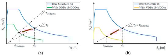
Figure 1.
Effect of energy-dissipating devices on the Acceleration–Displacement Response Spectrum: (a) DDDs; (b) VDDs.
VDDs are very versatile and have been employed in several applications [32,33,34]; however, they are particularly indicated for flexible structures, such as high-rise buildings and long-span bridges [33,35]. Strategic buildings, such as hospitals, are particularly sensitive to the effects of earthquakes, given the presence of medical equipment and other technological content (e.g., surgery rooms, gas pipes, etc.) highly susceptible to accelerations or deformations caused by earthquakes [36]. VDDs are also largely employed in bridges to accommodate uncontrolled slow motions (like thermal motions) and guarantee protection from seismic and wind loads [37,38].
Based on their reaction to seismic input, energy dissipation devices are further classified into three categories [39,40,41], namely active, passive, and semi-active seismic control systems. Active control systems are capable of actively counterbalancing seismic actions by adjusting their characteristics. They employ sensors and computerized control to monitor and respond to the structural excitations in each time instant. These systems require a large external power supply to operate [42]. On the contrary, passive control systems do not require any external power supply or equipment to operate. They are activated directly by the deformation of the buildings, and the force–velocity characteristic curve is fixed. Therefore, passive FVDs certainly improve the response of a structure, but the damping coefficient is a constant that limits the output of the damper within a certain range. Owing to the randomness and uncertainty of external loads, such as earthquakes and strong winds, the damper cannot adjust its working performance under different working conditions and different structural displacements to achieve reasonable energy dissipation and protect the structure. Consequently, classical FVDs cannot adapt to changes in the structural damping requirements. On the other hand, semi-active control systems combine the properties of the other two categories. Indeed, they use the motion of the structure, as passive devices, to trigger the control forces, but they can adjust the intensity of their response as active devices through a small external power source. The control of the developed forces is achieved thanks to a sensing system that measures the structural response [14]. However, the presence of external equipment increases the complexity of the damper [43], which explains why these systems are still not employed in construction projects. To address this issue, adaptive FVDs have been recently developed. These devices do not require any external equipment to operate but can automatically adapt their behavior to external excitation through a mechanical system. This behavior requires a more complex design of the adaptive device with respect to the others, and their development is currently ongoing.
The state of the art of seismic protective systems based on energy dissipation has been the subject of several reviews [13,14,40,44,45,46]. Hu et al. [44] conducted a review on passive Metallic Yielding Dampers and Fluid Viscous Dampers (FVDs); Spencer and Nagarajaiah [40], Symans and Constantinou [14], and Xu et al. [46] focused their research on semi-active devices only, while Soong and Spencer [45] presented a study on active, semi-active, and hybrid devices. An updated review of the technological development of FVDs, with a particular focus on semi-active dampers with adaptive behavior, is the subject of the present paper. The main types of FVDs proposed and studied in the past 30 years have been highlighted, showing their working principles and design characteristics, and then attention is focused on the most recent research in the development of semi-active and adaptive devices. The present state of the art is not intended to be comprehensive due to the continuous development of new devices and technologies.
The paper is divided into three sections. Section 2 deals with passive FVDs by presenting their main components and the constitutive behavior. Then, a description of modeling techniques of FVDs and a historical review of their evolution is provided. Section 3 introduces semi-active FVDs by describing the constitutive law of electrorheological, magnetorheological, and variable stiffness/damping devices. Finally, Section 4 is focused on adaptive FVDs.
2. Passive Fluid Viscous Damper
Conventional FVDs with passive behavior are typically composed of a hollow cylinder filled with silicon oil (or a similar type of fluid) and a piston rod with a head provided with orifices [47], which divides the cylinder’s inner volume into two chambers, as shown in Figure 2 [31,48]. When an external action excites the device, the piston moves, and the fluid is forced to pass from one chamber to the other through the orifices of the piston head. Once the fluid expands into full volume in the second chamber, it slows down and loses its kinetic energy into turbulence [48]. The different pressure between the two chambers produces the damping force [48,49], while the friction forces triggered in the orifices of the piston head dissipate energy in the form of heat. If the damper is subjected to long-duration or large-amplitude motions, the internal temperature rise can be relevant [50,51] and may cause damage to the damper. Moreover, the temperature rise reduces the viscosity of the fluid, affecting the effectiveness of the device [52].
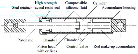
Figure 2.
Scheme of a classical passive FVD [47].
The piston rod is made of polished stainless steel and is sufficiently rigid to avoid buckling and bending under cyclic loading. The cylinder is normally a seamless steel tube designed to withstand the pressure generated by the internal fluid. Fluid conforming with the European standard EN15129 [15] must be fire-resistant, nontoxic, thermally stable, and not degrading with age. Moreover, it must be non-flammable and non-combustible. The silicone fluids normally employed in FVDs are thermally stable, completely nontoxic, and characterized by a flash point over 340 °C. Other fluids are allowed only if the requirements of EN15129 [15] are respected. Seals are used in order to avoid leakage of fluid from the damper. Since dampers may remain idle for long times, these seals must be free of long-term sticking and fluid seepage; for this reason, they are made of a high-strength structural polymer, such as Teflon, stabilized nylon, or acetyl resin family members. The accumulator, shown in Figure 2, accommodates changes in volume caused by the thermal expansion of the fluid and the volumetric displacements induced by the piston rod. The accumulator has the additional function of preventing undesirable restoring forces coming from the reduction in the volume of the fluid due to the piston rod movement [53]. The orifices control the flow of fluid across the piston head and, consequently, the level of energy dissipated by the damper.
FVDs generally provide an equivalent viscous damping almost equal to 25% [48]. Indeed, as an example, a reinforced concrete structure equipped with FVDs is able to reach a total damping of 30%, where approximately 25% is the damping directly introduced by the dampers, while the remaining 5% corresponds to the structural damping. It must be recalled that FVDs do not affect the fundamental period of the structure thanks to their out-of-phase behavior with respect to the structural forces and displacements [48].
The behavior of passive FVDs is generally described by using Equation (1) [54], which shows that the force of the damper is proportional to the relative axial velocity between the piston and the cylinder:
where is the damping coefficient, is the damping exponent, is the axial velocity of the damper, and is the signum function. The values of and depend upon the hydraulic circuit used in the device [55,56].
FVDs are classified based on the value of the damping exponent α: (i) linear FVDs are characterized by ; therefore, the corresponding damping force is directly proportional to the axial velocity; (ii) non-linear FVDs are described by Equation (1) with ; (iii) ultra-linear FVDs are defined by [30].
Figure 3a shows the influence of the exponent on the shape of the force–displacement diagram of an FVD, while Figure 3b depicts the force–velocity curves considering different values of and a constant damping coefficient. As decreases, the area of the force–displacement hysteresis loop gets larger, with a consequent increase in the dissipated energy [55]; indeed, the shape corresponding to an FVD characterized by α = 1 (linear FVD) is close to an ellipse, while it gets closer to a rectangle as tends to zero. The ultra-linear FVDs (with values of α up to 1.8–2), as well as linear FVDs, are normally employed in applications where the structure is primarily excited by wind forces since these systems behave as shock-transmitting or lock-up devices that tend to develop large forces at high velocities [1,54], as shown in Figure 3b. Non-linear FVDs are preferred for the protection of structures from earthquakes since they are able to dissipate a great amount of seismic energy, larger than that of linear and ultra-linear FVDs [57], over a large number of frequencies (Figure 3a). As a drawback, the high energy dissipation releases a huge amount of heat, causing a temperature increment in the device; this may be an issue in the case of long-term excitation, like in the case of wind excitation [34].
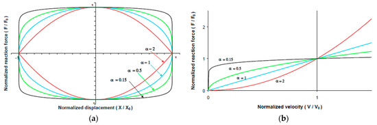
Figure 3.
Force–displacement curves (a) and force–velocity curves (b) for passive FVDs with different α exponents [57].
2.1. Design Methods for FVDs in Buildings
FVDs can be adopted in both new and existing structures to provide supplementary dissipation of seismic energy. In framed structures, these devices are usually incorporated within steel braces, where the most popular configurations of damped braces are the diagonal, chevron, scissor jack, and toggle ones [58].
Several procedures are reported in the literature for the design of FVDs. Normally, the design is performed in order to guarantee the protection of buildings from earthquakes of high intensity corresponding to the ultimate limit state [59,60,61]. These methods aim at determining the FVDs’ fundamental properties, namely the damping coefficient and the damping exponent It is possible to categorize current design methods into three families determined by the input parameters. The first group, named Damping-Based Design method, consists of evaluating the damping coefficients of the added viscous dampers by selecting, as a first step, a damping ratio of the structure based on a chosen target level of structural performances. The properties of the single FVD are then distributed at each floor, depending upon the specific structural characteristics of the case-study structure, such as the floor masses and the inter-story lateral stiffnesses [1,62,63]. In the second group, called Displacement-Based Design method, a target displacement demand (e.g., inter-story drift, roof displacement, etc.) is defined, and the FVDs are designed in order to guarantee the selected structural performance under the design earthquake. Based on that target-displaced configuration, a “substitute” single degree of freedom (SDOF) model is evaluated and used to replace the multi-degree of freedom (MDOF) structure. The substitute SDOF model consists of an equivalent linear system characterized by an effective (secant) stiffness and an effective energy dissipated, represented through an equivalent damping ratio. Once the properties of the SDOF FVD are determined, the distribution of the properties of the dampers at each story of the structure is performed depending on the displacement or the story shear [64,65,66]. The Energy-Based Design methods belong to the third group, where the properties of the FVDs to be inserted at each floor of the analyzed structure are selected based on the amount of seismic energy to be dissipated [67,68,69].
2.2. Modeling of Passive Fluid Viscous Dampers
The mechanical behavior of an FVD can be ideally described through the rheological model of a viscous dashpot element [70,71], as shown in Figure 4.
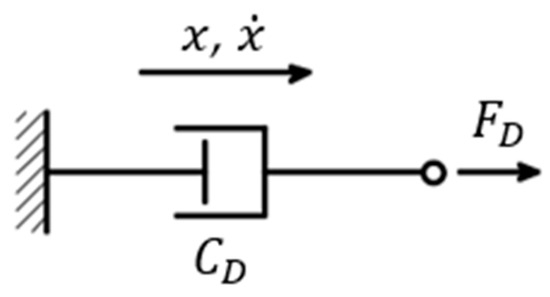
Figure 4.
Model of a viscous dashpot (adapted from [71]).
The purely viscous model is valid only under a certain cut-off frequency [17,54] and, in particular, for frequencies lower than 4 Hz, for which no additional stiffness can be included [1]. However, an accurate prediction of the structural response is obtained by a more complex mathematical model that also considers the small stiffness generated by the device under compression [71,72,73]. In many applications, FVDs are encased in bracing systems, and a reliable mathematical model should also include the stiffness of the brace [74,75]. To this scope, different models were developed [31,71,76,77], and the Kelvin–Voigt model [78] as well as the Maxwell model [44,79] are the ones most largely adopted and implemented in the principal Finite Element Method (FEM) software programs, such as MidasGen 2023 [80] and SAP2000 v25.0.0 [81]. Between them, the Maxwell model is more common because it is more accurate when representing the viscous damping force [74,78,82,83], as it is able to capture the relaxation time of FVDs [74,83,84]. On the other side, the Kelvin–Voigt model is not able to exactly reproduce the dependency of the FVD’s behavior upon the frequency of the external excitation, tending to underestimate the FVD’s force, especially at low frequencies [78].
In particular, the Maxwell model consists of a spring and a dashpot connected in series (see Figure 5a). This model satisfies the kinematic conditions expressed in Equation (2) and the force condition reported in Equation (3):
where , and , are, respectively, the displacement and the velocity of the dashpot (, ), of the spring (, ), and their combination (, ) [44]. in Equation (3) is the stiffness of an equivalent spring that includes both the stiffness of the bracing system and the inherent stiffness of the FVD [75].
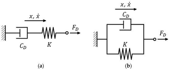
Figure 5.
(a) Maxwell model and (b) Kelvin–Voigt model (adapted from [44]).
2.3. Passive Fluid Viscous Damper: Critical Review of Past Studies
The evolution of FVDs began with the military and aerospace industry [17,31]; the first device, similar to modern dampers, was introduced in the 1860s to reduce the recoil of cannons. During World Wars I and II, fluid dampers were largely used in large cannons, guns, and aircraft but also in the automotive field. With the advent of the Cold War, these devices were turned into various industrial applications, such as energy-absorbing buffers in steel mills, canal lock buffers, and offshore oil leg suspension alongside shock and vibration isolation [17,53,74]. From the last decades of the 20th century up to now, the technology of FVDs has been adapted to applications related to the protection of structures from earthquakes and wind. One of the first studies that tackled the use of FVDs encased in steel braces for the seismic protection of buildings was carried out by Constantinou and Symans [85]. They proposed a device (Figure 2) characterized by a linear behavior and able to operate over a wide temperature range (from −40 °C to +70 °C). A further step was made by Seleemah and Constantinou [54], who developed four different configurations of FVDs (Figure 6), characterized by a non-linear response and obtained by modifying the geometry of the orifices. Through an experimental investigation, they demonstrated that non-linear devices were able to produce a higher reduction in displacement response than linear devices [54].
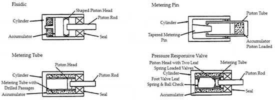
Figure 6.
Four configurations of the passive FVDs of Seleemah and Constantinou [54].
Similar studies were conducted by the Taylor company [31], whose first device for civil application was characterized by a huge size (Figure 7) [31]. In the following years, the company produced smaller devices that could be installed in brace configurations as well as components of base isolation systems in buildings [48].
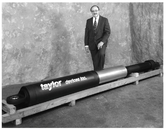
Figure 7.
A Taylor Company FVD [31].
FVDs are commonly used as velocity-dependent passive energy devices in dissipative bracing systems around the world due to their exceptional damping performance, stable mechanical properties, simple installation procedures, and cost-effectiveness [32,67,86]. For these reasons, the FVDs have been widely used in the last decades in new reinforced concrete structures and steel ones, but also for retrofit intervention [87]. The FVDs can be effectively used on buildings of different heights [76,88].
In tall buildings, the FVDs, especially non-linear ones, are very useful because they are able to dissipate high values of seismic force at high velocities [89]. A practical application of these devices on high-rise buildings is the 181 Fremont skyscraper built in San Francisco in 2017, which is a 56-story steel building (Figure 8a). The peculiarity of this project is that the FVDs are placed inside the structure through a mega brace system that is able to provide damping within the length of the braces spanning multiple floors [89]. Another example is the Allianz Tower, a 50-story concrete building built in Milano in 2015 (Figure 8b). Here, a set of eight localized external viscous dampers was installed, with the primary goal of improving the service life behavior in terms of comfort under wind loads and, additionally, of guaranteeing a proper structural response under seismic loads correspondent to the Life Safety Limit State [34].

Figure 8.
(a) 181 Fremont skyscraper, San Francisco; (b) Allianz Tower, Milano [34].
Thanks to the reduction in absolute acceleration and displacement, FVDs can be placed in strategic buildings such as hospitals. Indeed, hospitals are particularly sensitive to the effects of earthquakes, given the presence of medical equipment and other technological content (e.g., surgery rooms, gas pipes, etc.) that are highly susceptible to acceleration or deformations caused by earthquakes [3]. Miyamoto et al. [90] and Mokhtari and Nadarpour [75] showed that FVDs have a considerable impact in reducing both structural and non-structural damage, hence improving the functionality and seismic resistance of the upgraded structure.
FVDs have been widely adopted for the seismic protection of bridges. These devices are appropriate for both retrofitting existing vulnerable bridges and designing new ones [91,92]. Indeed, the viscous dampers efficiently dissipate energy and reduce the movement of the bridge induced by braking, wind, and seismic loading. In addition to that, FVDs do not provide any valuable restriction at slow velocities, accommodating service slow motions like the ones induced by thermal movements [91].
Infanti et al. [92] studied the seismic retrofit of the Seohae Grand Bridge in Korea, which is composed of three different types of bridges: a cable-stayed bridge (990 m), a free cantilever method (FCM) bridge (500 m), and a precast span method (PSM) bridge (5820 m). The PSM bridge consists of a series of continuous spans that were not able to satisfy the seismic safety requirement. Therefore, 54 viscous dampers were placed between the superstructure and the pier to protect the structure against strong earthquakes. The adopted devices were able to exert a force equal to 500 kN at a velocity of 240 mm/s. Moreover, these devices were operative over a wide range of temperatures, from −25 °C to 40 °C.
Another iconic application of FVDs on bridges is the retrofit performed on the London Millenium Bridge built over the river Thames in London (United Kingdom). When the bridge was opened, it exhibited large lateral displacement induced by pedestrian motion. Thus, 37 FVDs were installed in three different configurations to prevent lateral, vertical, and torsional modes. The additional devices prevented resonance of any mode and allowed the bridge to produce an equivalent viscous damping of 20% instead of the original 0.5%.
Another example is the Rion-Antirion Bridge, which was designed to resist seismic excitations with a return period of 2000 years and a PGA equal to 0.48 g through a seismic protection system made by fuse restraints and FVDs [93]. This bridge, located in the Gulf of Corinth in Greece, consists of a 2252 m long suspension bridge with four pylons and two approach viaducts. The main bridge is protected by fuse restraints that work in parallel with the dampers. The first type of device protects the bridge from excitations induced by the wind or by moderate earthquakes. Under excitations equal to or stronger than the design earthquake, the fuse restraints are designed to fail so that the FVDs are able to dissipate the input energy. Figure 9a shows the completed Rion-Antirion Bridge, and Figure 9b shows the seismic protection system installed in each of the four pylons. The approach viaducts are designed to withstand the same seismic event as the main bridge, and their seismic protection systems are composed of elastomeric isolators and FVDs.
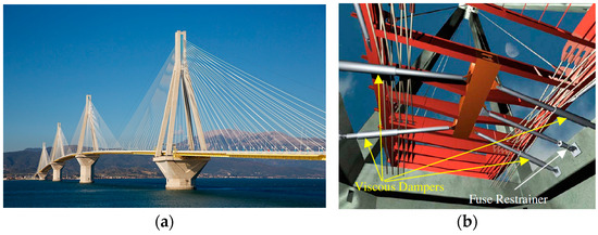
Figure 9.
(a) The Rion-Antirion Bridge; (b) the seismic protection system of the suspended bridge [93].
3. Semi-Active Fluid Viscous Dampers
Passive FVDs described in Section 2 provide a fixed response curve, whatever the intensity of the seismic action. They are typically designed with a focus on the ultimate limit states, aiming to prevent structural collapse and ensure the safety of occupants during a severe seismic event. The effects of earthquakes with lower intensities, which are more frequent during the service life of a building, may not be totally mitigated by passive FVDs, and this represents an important drawback of this technology. Indeed, weaker seismic events may not pose a significant risk of structural failure but can compromise the non-structural elements inside the building and adversely affect the overall serviceability and functionality of the structure. To address this issue, semi-active and adaptive FVDs have been actively investigated in the last few decades. These damping systems are designed to provide variable damping characteristics, allowing them to respond more effectively to a broader range of seismic intensities. By adapting their response according to the specific seismic excitation, these FVDs can enhance the protection of non-structural elements and improve the overall performance of the building during serviceability limit states.
Semi-active energy-dissipating systems are generally based on the same working principle as passive FVDs, but they are provided with a sensing and a control system [14]. The sensing system detects either external excitations or structural response information and transmits them to the control system. Sensors can be placed inside the device or directly on the structure. However, sensors are a critical component, as their signal may be affected by external factors, such as magnetic or electric fields, as well as environmental noise [94]. Originally, the sensing system was placed on the structure [13,95], but this configuration increased the complexity and the cost of the system [96,97]. For this reason, in the last decades, devices equipped with self-sensing components able to detect accelerations, forces, and displacements have been studied [94,98]. The signal from the sensing system is analyzed by the control system and feeds into a control law that allows efficient control forces to be developed. The control laws can be divided into two categories [99]: the first one comprises conventional control algorithms such as the optimal control algorithms [100], Lyapunov stability theory [101], skyhook, and continuous sliding mode [102]; the second category comprises the fuzzy control method [103,104], neural network [105], and genetic algorithms [46]. The first category of control algorithms are model-based algorithms, and their efficiency relies on the accuracy of the model. The algorithms belonging to the second category are based on the measured response of the structure. The semi-active systems are indeed capable of adjusting their behavior under different conditions and different structural responses to achieve the amount of energy dissipation necessary to protect the structure [45,46,95,106]; for this reason, they are also called “controllable passive devices” [14]. They operate with a small external energy supply (e.g., a battery) with a power of the order of tens of watts [107].
The semi-active energy-dissipating systems developed in the last decades include magnetorheological (MR) dampers, electrorheological (ER) dampers, and variable orifice dampers [108].
3.1. Rheological Fluid Viscous Dampers
Rheological fluids are those fluids that change their viscosity in the presence of a magnetic field (MR fluids) or an electric field (ER fluids). This process is completely reversible, and the fluids return to their original viscosity as soon as the magnetic or electric field is removed. The specific behavior of MR and ER fluids is detailed in Section 3.1.1 and Section 3.1.2, respectively.
The increment in the viscosity is caused by the structure of the fluids’ particles, which are polarized under the electrostatic or magnetic field and form columns following the direction of the applied field, as shown in Figure 10. The formation of the column structure allows sustaining shear forces that are applied perpendicularly to the electric field, thereby increasing the viscosity of the fluid [109,110]. Whenever the column structure is activated, the fluid particles require a minimum amount of force to be moved. The force over which the particles start moving is called yield strength. The higher the applied electric/magnetic field, the higher the force required to move the fluids’ particles.
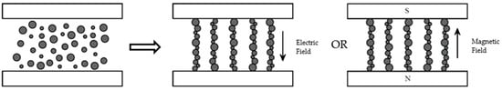
Figure 10.
Behavior of ER and MR fluids (adapted from [46]).
A common feature of both types of devices is the presence of two surfaces, which are electrodes in ER dampers and poles in MR dampers. They are used to generate either an electric (ER dampers) or a magnetic (MR dampers) field. ER dampers are divided into three typologies depending on how the rheological fluid operates. MR dampers, on the other hand, are divided into four types, with three of them being the same as those for ER dampers, while the fourth one is unique to MR devices [46]. The first typology operates in flow mode (Figure 11a), which is characterized by two stationary surfaces, and the flow rate of the fluid is modified by varying the intensity of the electric or magnetic field. The second typology is based on the shear mode of operation (Figure 11b), which is based on the application of a relative motion between the surfaces perpendicular to the direction of the electric or magnetic field; this motion produces a shear force on the ER or MR fluid that triggers the flow. The intensity of the applied shear force can be modified through the intensity of the electric or magnetic field. The third mode of operation is the squeeze-flow mode (Figure 11c), which consists of the relative movement of the surfaces in the direction parallel to the electric or magnetic field. The movement of the electrodes induces an alternate tension/compression state of stress in the fluid [46]. Figure 11d shows the magnetic gradient pinch mode, which is a mechanism distinctive to MR devices. This mode works with magnetic poles placed along the flow path of the fluid and separated by a non-magnetic material. This arrangement creates an elliptical magnetic field near the wall of the orifice, which allows the diameter of the orifice to be controlled by changing the intensity of the magnetic field; the stronger the magnetic field, the higher the reduction in the orifice’s diameter [111].
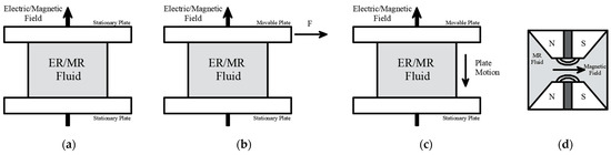
Figure 11.
ER and MR fluids’ operating modes: (a) flow mode; (b) shear mode; (c) squeeze-flow mode; (d) magnetic gradient pinch mode (adapted from [46]). N: north pole of the magnetic field, S: south pole of the magnetic field, F: force.
Table 1 provides typical ranges of the properties associated with ER and MR fluids in terms of yield strength, voltage power supply, maximum magnetic/electric field, viscosity, density, and size of the particles. Both MRs and ERs provide response times in the order of milliseconds. ER fluids can be easily produced in a laboratory and require a simpler system to be excited by an electric field. On the other hand, MR fluids provide a higher yield strength than ER fluids and require a lower voltage to be activated. Moreover, MR fluids have great stability over a wider range of temperatures [112,113]. However, MR fluids are heavier due to the presence of iron particles, and they are affected by sedimentation and aggregation [114]. For this reason, sometimes additives are included in the fluids in order to improve the strength between particles. The presence of additives is also used to have a quick reversal process, which allows the fluid to return to its original viscosity when the magnetic or electric field is removed [115]. An effective reversal process is important to have a device always ready to adapt its behavior to new conditions.

Table 1.
Comparison of ER and MR fluids’ properties [112,116].
3.1.1. Electrorheological Dampers
Electrorheological (ER) dampers are made of a cylinder, a piston, an ER fluid, and at least a pair of electrodes that produce the electric field (Figure 12).
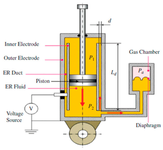
Figure 12.
Schematic example of ER damper [46].
The use of ER fluids was first introduced by Winslow [117], who exploited the variation in the rheological properties of the fluid given different electric fields to transform an electrical impulse into mechanical force [118]. When an electrostatic field is applied, the fluid viscosity changes and this permits a reversible transition from Newtonian fluid to a solid-like material. Indeed, whenever the electric field is removed, the fluid rapidly (within 10 milliseconds) returns to its original form [46].
Makris et al. [118] tested an ER fluid damper composed of a cylinder, a piston road, and a piston head that pusheshe ER fluid through an annular duct (Figure 13), where the electric field is applied. This configuration allows the ER fluid to operate according to the flow mode, where the level of the output force is controlled by the intensity of the electric field, whereas the damper behaves as a classical FVD when the electric field is not activated.
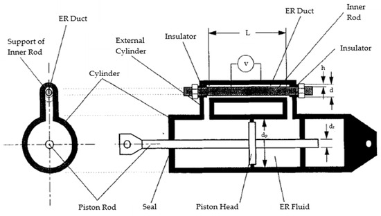
Figure 13.
ER fluid damper proposed by Makris et al. [118].
3.1.2. Magnetorheological Dampers
Magnetorheological (MR) dampers are semi-active devices made of MR fluids, characterized by iron particles of 1–7 μm diameter [119]. Whenever a magnetic field is applied, the MR fluid passes in a few milliseconds [112] from a Newtonian behavior to a chain-like structure along the direction of the magnetic flux (Figure 10), and the flow of the fluid through the orifices of the damper is triggered only if a minimum amount of shear stresses is generated by the motion of the shaft [46].
The commercial applications of MR dampers work with the flow and shear modes (Figure 11a,b) [120], while the squeeze-flow and the magnetic gradient pinch modes are not commonly used because of their complex circuit design [46].
Figure 14 shows an example of an MR damper developed by the Lord Corporation [46]. This device works according to the flow mode and is composed of two chambers and a piston rod where the electromagnetic coils are placed. The MR fluid flows from one chamber to the other through a gap between the piston and the wall inside the cylinder. The damping force of this device is controlled by the intensity of the magnetic field that is modulated depending on the excitation detected by the sensors [121].
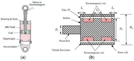
Figure 14.
MR damper developed by Lord Corporation [46]: (a) section of the device; (b) fluid path in the piston head and coil placement [121].
In the last decades, MR dampers working with the shear mode mechanism have also been developed [106,122]. An example is the device proposed by Yi et al. [106] and sketched in Figure 15. This system consists of two parallel steel plates, a moving plate coated with a thin foam saturated with MR fluid, and a single coil placed at one end of the device. The output force is generated by the sliding motion of the moving plate between the two parallel plates. By increasing the strength of the magnetic field, the device is able to produce a higher damping force and dissipate a larger amount of energy [123,124].
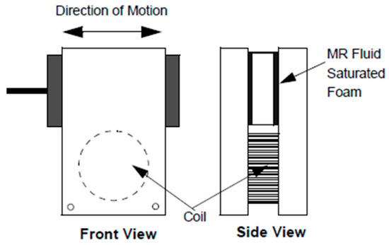
Figure 15.
MR damper proposed by Yi et al. [106].
MR dampers guarantee high output forces and stable hysteretic behavior within large temperature fluctuations; specifically, the force varies less than 10% in the range of temperatures between −40 °C and +150 °C [125].
3.1.3. Modeling of ER and MR Dampers
Popular models used to represent the behavior of MR and ER dampers are the Bingham model [126,127,128,129,130] and the Bouc–Wen model [131,132,133], largely used in many studies. However, other models suitable for reproducing the response of both MR and ER devices are available in the literature, as reviewed by Xu et al. [46] and Lenggana et al. [134].
The Bingham model is characterized by a friction element in parallel with a viscous damper (Figure 16a); the damping force is given by the expression of Equation (4):
where is the frictional force related to the fluid yield stress and is the offset of the force to account for the nonzero mean that can be observed in the measured force due to the presence of an accumulator [129]. This model represents the force–velocity relationship through a bilinear curve. Figure 16b shows that the Bingham model is not able to perfectly describe the real behavior of the rheological damper, especially at low velocities [129].
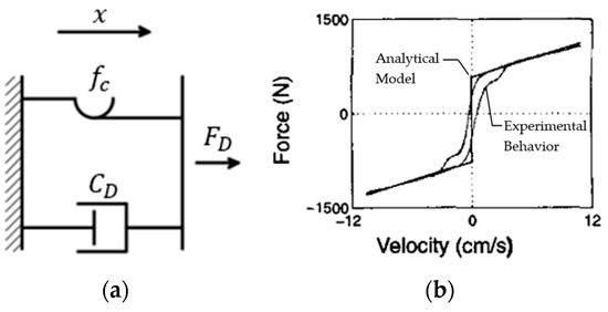
Figure 16.
(a) Bingham model (adapted from [46]); (b) force–velocity response of the Bingham model ( [129].
The Bouc–Wen model [135,136] is frequently adopted for its versatility and capability of representing the wide variety of hysteretic behaviors typical of both MR and ER dampers; moreover, it allows control of the intensity of the device’s output force [134]. The scheme of the Bouc–Wen model is shown in Figure 17a, where the output force of the damper is described by Equation (5):
where is the stiffness induced by the accumulator, is the initial displacement of the spring, and is an evolutionary variable governed by the law reported in Equation (6):
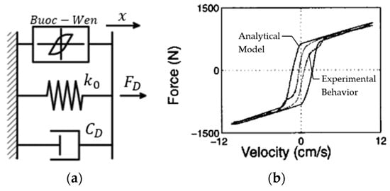
Figure 17.
(a) Bouc–Wen model (adapted from [46]); (b) force–velocity response of the Bouc–Wen model [129].
The parameters , A, and allow the shape of the hysteresis loop to be controlled, while controls the smoothness of the force–displacement curve; all these parameters can be calibrated through experimental evidence [46]. By changing the parameters of Equation (6), the Bouc–Wen model is able to describe the linearity in the unloading phase and the smoothness of the transition between the pre-yield and post-yield region [129]. Figure 17b shows the comparison between the force–velocity loops of the Bouc–Wen model (the outer curve) and the one derived from experimental evidence (the inner curve).
Like the Bingham model, the Bouc–Wen model is also not suitable for describing the behavior of devices in the regions at low velocities. To overcome this issue, Spencer et al. [129] developed a refined model consisting of a Bouc–Wen model that works in parallel with a spring and in series with a viscous dashpot, as represented in Figure 18a. The force generated by the model is expressed by Equation (7):
where allows the stiffness at large velocity to be controlled and is given by Equation (8):
where is the damping coefficient that controls the behavior of the device at low velocity. Figure 18b represents the predicted force–velocity loops and the experimental data [129]. As can be seen, the two curves are almost overlapping, showing that the proposed model is able to reproduce the behavior of the rheological damper quite well. However, the model is rather complex to be implemented in commercial software programs and is defined by a huge number of parameters that must be calibrated upon experimental tests.
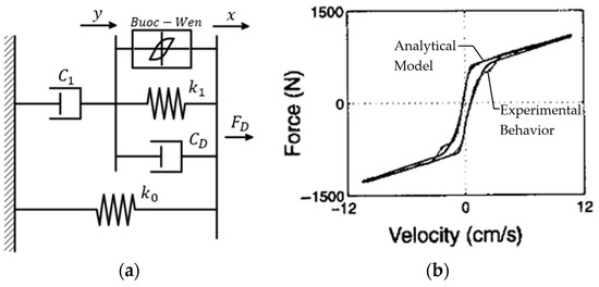
Figure 18.
Model proposed by Spencer et al. [129]: (a) rheological model (adapted from [129]); (b) force–velocity response.
3.1.4. Applications of ER and MR Dampers
MR devices have been used in several engineering fields, which range from the industrial area [137,138], where they are employed as vibration dampers in washing machines or seat dampers for commercial vehicles, to the automotive area [139,140,141], in which they are used as semi-active suspensions for vehicles, and to the aerospace field [142,143,144], where they are employed as landing gears or helicopter rotors. MR dampers were adopted in the civil engineering field to protect structures from earthquakes and wind [145,146,147]. In 2001, Sodeyama et al. [147] studied and developed an MR damper able to provide a maximum damping force of 300 kN. Two devices were installed in the Tokyo National Museum of Emerging Science and Innovation between the third and fifth stories, as shown in Figure 19a. MR dampers were also used for the protection of bridges from wind and seismic excitations. Chen et al. [148] installed 312 MR dampers, produced by the Lord Corporation, on the 156 stay cables of the Dongting Lake cable-stayed bridge (Figure 19b) since the structure was too sensitive to vibrations induced by rain and wind. Thanks to the installation of MR devices, the vibrations of the cables and the deck were consistently reduced.
On the other hand, ER devices did not find widespread commercialization because of their weak yield stress, low suspensibility, and low stability [149].
In 2003, Wen et al. [150] presented an ER fluid characterized by a yield strength of 130 kPa [149,151], which was considerably higher compared to that of classic ER fluids, ranging in the order of a few kPa (e.g., the ER device presented by Makris was characterized by a yield strength of 13 kPa [118]). Therefore, the new ER fluid was called giant electrorheological (GER) fluid. Its behavior was similar to the other ER fluids, with a viscosity that increased with the strength of the electric field. Devices filled with GER fluid are able to produce a high damping force with a low stiffness effect. Moreover, these devices can adapt their behavior by requiring a lower power consumption [152].
After the study of Wen et al. [150], other devices with GER fluid were presented [153,154]. An example is the damper studied by Sun et al. [153], who exploited the shear mode mechanism; experimental results showed the capacity of these systems to dissipate vibrations up to 90%, with a limited stiffness effect. Pu et al. [154] proposed a device made of GER fluid that works with the squeeze mode mechanism; however, this system is addressed for applications in the robotic and bionics fields; therefore, further research is necessary to extend its use to the civil engineering area.

Figure 19.
Application of MR dampers: (a) Tokyo National Museum of Emerging Science and Innovation [147]; (b) Dongting Lake cable-stayed bridge [155].
3.2. Variable Orifices Fluid Viscous Dampers
In variable orifices FVDs, the adaptive behavior is gained by changing the fluid’s flow through the application of external control valves. Two different typologies of control valves were proposed, namely solenoid valve adopted for an on–off control and servo-valve for a variable control [14].
3.2.1. FVDs with Solenoid Valves
Semi-active FVDs equipped with solenoid valves are made of a cylinder filled with hydraulic oil, a piston attached to a piston rod, and a valve in a bypass pipe that connects the two sides of the cylinder (see Figure 20a).
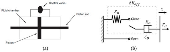
Figure 20.
Variable stiffness damper: (a) section of the device [123]; (b) rheological model of the system composed of the damper and the brace (adapted from [46]).
These systems are also called variable stiffness FVDs since they are capable of varying the natural frequency of the controlled structure by changing the additional stiffness introduced by the damper, thus avoiding the resonant condition during earthquakes. The solenoid valve has two stages, namely an “on phase” and an “off phase”. When the valve is closed, the flow of the fluid between the two chambers within the cylinder is prevented, and the device behaves as a rigid link that provides additional stiffness to the structure. If the damper is encased in a brace, an equivalent effective stiffness () is transmitted to the building, which is a combination of the stiffness of the damper ) and the stiffness of the brace ), computed according to Equation (9):
On the contrary, when the valve is open, the fluid is free to flow between the two chambers through the bypass pipe, and there is no stiffening effect. In this configuration, the damper provides certain damping () [46], and the constitutive behavior corresponds to the mathematical model of a single dashpot, as shown in Figure 4.
Kobori et al. [156] proposed a variable stiffness device (VSD) composed of a cylinder with two chambers that are connected by a pipe in which the solenoid valve is inserted. This system needs a low-power source to work (20 W); if the power is interrupted, the valve automatically closes the pipe that connects the two chambers, guaranteeing the protection of the structure in every situation.
He et al. [157] focused on variable stiffness FVDs too, in order to reduce the vibrations induced by earthquakes or by winds on cable-stayed bridges, demonstrating that these systems were able to reduce the displacement of the deck and the shear and bending moment of the bridge’s towers. Kori and Jangid [123] studied a semi-active variable stiffness damper to find the optimal stiffness ratio to be introduced into the structure. In particular, they performed a parametric study on possible structural configurations by considering different damper deployments. Their results showed that the floor displacements diminished by increasing the stiffness of the dampers and, thanks to the dissipated energy, the inter-story drifts and the top floor’s acceleration were consistently reduced. Luca and Pastia [158] studied the efficiency of an FVD with a solenoid valve applied in a single degree of freedom (SDOF) structure by demonstrating that this system allows a reduction in the displacement response greater than that obtained by a passive device.
3.2.2. FVDs with Servo-Valves
While devices equipped with solenoid valves can implement only two different behaviors due to the on–off property of the valve itself, devices equipped with servo-valves are able to dynamically adapt their response depending on the intensity of the excitation. They provide the structure with values of damping ranging between a maximum and a minimum level [46], thanks to the servo-valve’s property of actively controlling its opening. For this reason, they are also called variable damping dampers. The variable damping damper works as a passive FVD and is characterized not only by orifices through the piston head but also by a secondary orifice in a bypass pipe that connects the two chambers. The bypass pipe is equipped with a servo-valve that controls the flow of the fluid through the secondary orifice (Figure 21). When the valve is closed, the viscous fluid flows from one chamber to the other only through the orifices in the piston head, while if the valve is open, the fluid flows both through the piston head and the bypass pipe. The flow of the fluid through the bypass pipe varies depending on the opening of the servo-valve. Therefore, the damping coefficient ranges from a maximum . when the valve is completely closed to a minimum when the valve is open.
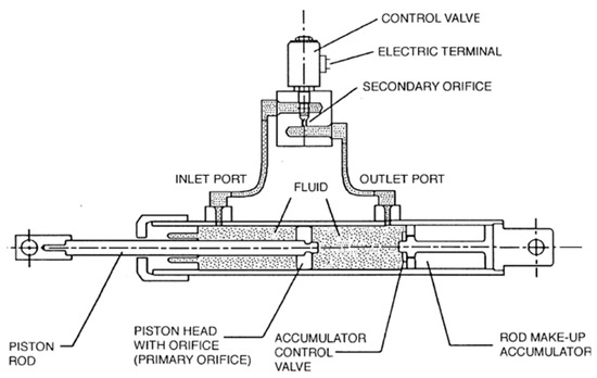
Figure 21.
Semi-active FVD equipped with servo-valve [159,160].
Symans et al. [159] developed a variable damping FVD with a fail-safe property: if a power loss occurs, the servo-valve automatically closes, allowing the device to operate as a passive FVD with maximum damping characteristics. This device requires a small power source to be operative (around 3.5 W, similar to a battery).
Kawashima et al. [161,162] and Patten et al. [163] studied analytically and experimentally a device aimed to control the seismic response of bridges. They realized shake table tests on a model of a simple-span girder bridge and demonstrated that the variable damping force provided by the servo-valve prevented small vibrations induced by traffic and wind loads and was able to reduce by up to 44% the displacement at the peak acceleration. Symans and Constantinou [160] focused on the application of the device in Figure 21 inside a laboratory test of a three-story steel structure. They performed shaking table tests on that structure and noticed that the dampers were able to improve the structural response by generating a large range of damping. They compared the performance of the variable damping FVDs with that of an active tendon control system. The results demonstrated that the tested semi-active system provided a damping larger than that of an active tendon control system, with a consequent larger response reduction. In particular, the semi-active FVDs were able to reduce the top-floor acceleration and the story drifts by 47% and 51%, respectively, while the active systems produced corresponding reductions of 38% and 32%.
Niwa et al. [164] employed variable damping devices for the seismic protection of a four-story steel office building in Shizuoka. Through dynamic tests, they verified that the devices, even with a small amount of electric power (70 W), were able to control the structural response of the case-study building during strong earthquakes, providing a damping force of 1 or 2 MN.
Shmerling and Gerdts [165] adopted the damper proposed by Symans et al. [159,160] to numerically verify the seismic protection of a 10-story rigid frame structure and studied an optimum control strategy to adjust the opening of the servo-valve at each time step during an earthquake. They demonstrated that these systems were able to effectively reduce the maximum shear force and total accelerations in the case-study building.
4. Adaptive Fluid Viscous Damper
A main drawback associated with semi-active devices is related to the complexity of the sensor system and the control algorithm, which increases the product manufacturing cost, making their use not affordable in construction projects [43].
Therefore, in the last two decades, a new typology of FVDs with an adaptive behavior was developed; these systems are able to adjust their response to different external excitations thanks to their self-sensing and self-controlling capabilities, gained by means of special valves or specific geometric properties [166].
Eyres et al. [167,168] investigated an FVD provided with orifices in the piston head and a bypass tube, which are opened by precompressed conical valves, as shown in Figure 22a. This damper behaves as a passive FVD up to a certain force , at which the relief valves open to allow the fluid to flow freely through the tubes. Each valve is connected to the cylinder by a precompressed spring, which guarantees that the valve remains closed when the fluid pressure is lower than the prestress of the spring. This FVD can be modeled exactly as a passive FVD by considering that the geometry of the orifices changes; in particular, the area of the orifices passes from , when relief valves are closed, to (), when the valves are open [167]. Therefore, this device is characterized by a linear piecewise behavior (Figure 22b) [168], and its response can be tuned by selecting different values of the precompression in the springs. Relief valves allow the maximum damping force, which is transmitted to the structure, to be limited, whatever the velocity. A damper similar to the one proposed by Eyres [167] was first applied to a helicopter’s rotorcraft systems by Bauchau and Liu [169] and Cacciola et al. [170].
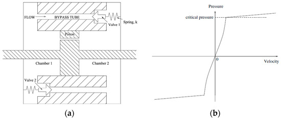
Figure 22.
Adaptive FVDs with relief valves: (a) geometry scheme [167]; (b) damper’s pressure–velocity characteristic [168].
Sakakibara [171] and KYB Corporation [172] proposed a device with relief valves (Figure 23), similar to the one of Eyres et al. [167,168], to be combined with a base isolation system for the seismic protection of buildings. In such combined systems, a passive FVD is normally designed considering earthquakes correspondent to the Life Safety Limit State [15,59]; consequently, the earthquake protective systems would be too hard, and, in the case of small seismic events, the property of reducing the induced accelerations into the structure may be lost. Therefore, this new damper was designed in order to develop a different response during earthquakes corresponding to either the serviceability limit state or the ultimate limit state. In particular, the device is characterized by the H-shaped force–displacement profile shown in Figure 23b, where a certain displacement threshold is set, at which the relief valves open, increasing the damping capacity of the damper [171]. The performance of the device was verified with wave vibration tests, and it was certified by the Japanese Minister as a seismic protection device [171]. However, the applications of this FVD in real structures have not been reported yet.
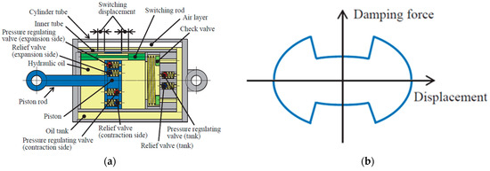
Figure 23.
Adaptive FVDs with relief valves [171]: (a) device configuration; (b) force–displacement profile.
All the passive, semi-active, or adaptive FVDs presented up to this point are characterized by a hysteresis loop that acts in all four quadrants of the force–displacement plane (Figure 24a), which determines an increase in the base shear demand due to the added resistive force provided by the device [173]. To overcome this issue, Hazaveh et al. [173,174] proposed a semi-active system, called semi-active direction- and displacement-dependent (D3) FVD, characterized by two sets of orifices in the piston head, where the inner set can be controlled according to three control laws, namely: (i) the 1–4 control law, in which the orifices are closed in all quadrants and the device behaves as a passive FVD (Figure 24a); (ii) the 1–3 control law, in which the orifices are closed only in quadrants 1 and 3, and the device exerts a resistive force only when the piston moves from its original position toward the peak displacement, while no force acts when the piston moves back to zero (Figure 24b); and (iii) the 2–4 control law, in which the orifices are closed in quadrants 2 and 4, and the resisting force applies only when the piston moves from peak displacement back toward zero (Figure 24c). Figure 24 illustrates how a semi-active device, governed by the three different control laws, affects the base shear force when installed within the structure. Hazaveh et al. [173,174] demonstrated that only the 2–4 control law can effectively reduce the structural response without increasing the base shear. Indeed, using the 2–4 control law, the retrofitted structure’s base shear () is equal to that of the undamped structure ().
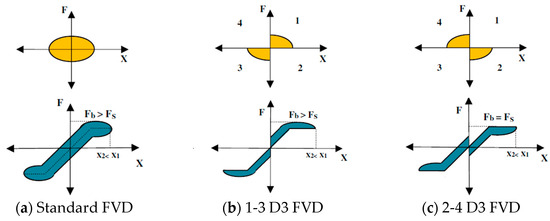
Figure 24.
Schematic force–displacement hysteresis loop for (a) a standard FVD, (b) 1–3 D3 FVD, and (c) 2–4 D3 FVD [173].
In order to avoid the complexity and the expenses typically associated with semi-active dampers, Hazaveh et al. [175] implemented this behavior on a passive device called passive D3, which is able to provide a damping force in single or multiple quadrants by modifying the geometry of the system and specifically by combining the use of one-way valves and different diameters of the internal cylinder. Figure 25 shows a single first-quadrant D3 device, which is composed of a piston head equipped with one-way valves and a cylinder characterized by a larger inner diameter on its left part. One-way valves are opened or closed by an annular plate that is linked through screws to the piston head. When the piston head is in the right half of the cylinder moving toward the positive direction, the annular plate closes the valves, and the device shows a resistive force in the first quadrant of the force–displacement hysteresis loop (Figure 25). When the piston moves in the opposite direction, the annular plate opens the orifices, and the device provides only a small amount of damping. The damping is even reduced when the piston is in the left half of the cylinder since the same mass flow rate of fluid is free to pass through the holes and the gap between the piston head and the cylinder.
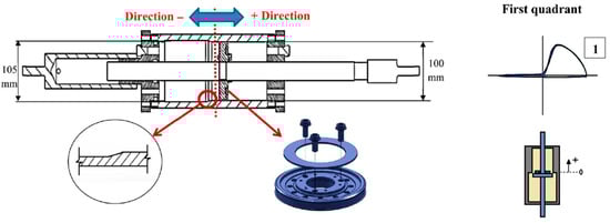
Figure 25.
First-quadrant passive D3 FVDs [175].
Figure 26 shows the 2–4 quadrant D3 FVD developed by Hazaveh et al. [175]. Indeed, passive devices characterized by the 2–4 control law [173,174] were designed by combining two pistons provided by one-way valves and a shared shaft in a single cylinder characterized by two stepped portions with different inner diameters, as shown in Figure 26. In this configuration, the movement toward the positive direction closes the valves of Piston 1 and opens the valves of Piston 2, while the opening and closing of the pistons is inversed in the negative direction (Figure 26). Even if these devices are promising, they were investigated only in laboratory tests [176], and, to the Authors’ knowledge, neither numerical tests on actual structures nor applications on real structures have been reported.
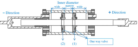
Figure 26.
The 2–4 passive D3 FVD [175].
Hormozabad and Zahrai [166] proposed the adaptive viscous damper (AVD) depicted in Figure 27. The device is composed of an external cylinder filled with viscous fluid, a piston rod, and a piston head made of two movable pieces. In particular, the piston rod is linked to a twin cone, which is connected through eight springs to a ring (Figure 27b). When the damper is at rest, the ring is aligned with the narrowest part of the cone; as soon as the piston starts moving, the drag force of the fluid compresses and stretches the springs, and the ring changes its position, reducing the passing area. Since the springs have a minimum length of 6 mm, the passage of the fluid is always guaranteed. The damping force of the AVD becomes bigger as the passing area gets smaller, and the damping coefficient ranges between an original value , when the piston head is in the rest position, up to , at the maximum elongation of the springs. The performance of the AVD was numerically compared with that of a passive FVD with a constant damping coefficient equal to installed in a two-story building, demonstrating a more than 50% reduction in displacement, 60% reduction in acceleration, and 40% reduction in base shear; moreover, the AVD was capable of dissipating more than 90% of the seismic energy than the passive FVD [166].
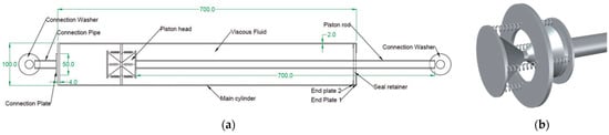
Figure 27.
AVD proposed by Hormozabad and Zahrai [166]: (a) layout of the AVD; (b) detail of the piston head.
Xu et al. [43] proposed a device in which the adaptive behavior is gained by varying the annular gap along the piston stroke instead of from the geometric properties of the piston head. In particular, this device, called variable-damping-coefficient viscous fluid damper (VCVFD), is characterized by two different diameters of the internal cylinder (Figure 28) that determine a multi-stage energy dissipation under different seismic levels, described by the dotted blue curve in Figure 29. There are three stages of variation of the damping force, depending upon the annular gap height between the piston head and the internal cylinder. In the first stage, the piston head is included in the area with an annular gap equal to (Figure 28a), and the output force is almost constant, as shown in the force–displacement loop of Figure 29. As the piston approaches the area with the annular gap equal to , the second stage starts (Figure 28b), and the output force increases. In the third stage, the piston head moves exclusively in the area corresponding to the annular gap of (Figure 28c), and there is a decrease in the output force.
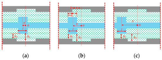
Figure 28.
Three stages of the VCVFD presented by Xu et al. [43]: (a) 1st stage, (b) 2nd stage, and (c) third stage.
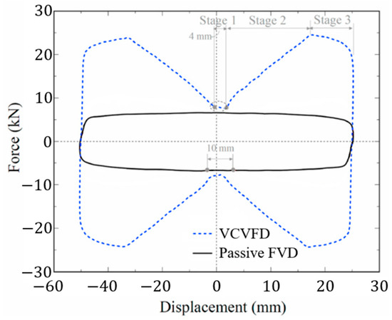
Figure 29.
Force–displacement loops of a VCVFD and a passive FVD (adapted from [43]).
Xu et al. [43] performed an experimental campaign on several prototypes of the VCVFDs characterized by different fluids and different dimensions of the internal gap. Moreover, they directly compared the performance of passive FVDs characterized by the same geometry as the VCVFDs. The results showed that the VCVFDs could develop larger damping forces than the passive FVDs (from 3.5 up to 6 times greater) and could dissipate more energy (around 2.9 times more). This is particularly evident by looking at Figure 29, where a direct comparison between the force–displacement loops of the VCVFD (dotted blue curve) and the passive FVD (black line) is reported. Xu et al. [43] studied the VCVFDs on a two-story full-scale frame. All the VCVFD prototypes were tested on the same steel frame that always remained in the elastic field, showing the great properties of the tested device. Indeed, the devices were able to protect the steel frame from experiencing plastic deformation.
Both the AVD and the VCVFD are still at the prototype stage and have not been employed in real structures yet. Indeed, according to Hormozabad and Zahrai [166], the AVD requires additional experimental research to demonstrate the reliability and robustness of its constitutive behavior because of its peculiar piston head configuration. Based on [43], the VCVFD needs a deeper study aimed at optimizing its structural parameters and numerical analyses performed on real structures.
5. Conclusions
Many FVDs are currently available, and their number is constantly growing. For this reason, this paper does not present a complete state-of-the-art on the topic, but it aims to provide an overview of the current trends in the field of FVDs used as energy dissipation systems for the seismic protection of structures. The various types of FVDs and their different configurations have been briefly investigated, starting from the simplest ones—the passive FVDs—to the more complex semi-active and adaptive FVDs.
FVDs are velocity-dependent devices, providing a force that is out of phase with respect to the structure’s internal forces and displacements caused by seismic excitation. Therefore, these devices can dissipate energy without overloading the structure. The first passive FVDs to be developed were derived from the devices used as shock absorbers in the military and aerospace fields. Starting from the 1990s, FVDs were largely adopted for the protection of structures and infrastructures against earthquake and/or wind excitations.
Passive FVDs provide a fixed response curve, whatever the intensity of the seismic action. Moreover, they are usually designed considering the seismic action effects at the ultimate limit states, where the target is to avoid the collapse of the structure and protect human life. But, on the other hand, FVDs tailored for the design earthquake may provide an insufficient response to earthquakes of lower intensity, typical of service limit states, which may not damage the structure but can jeopardize non-structural elements and reduce the serviceability of the building. For this reason, many semi-active and adaptive FVDs have been studied in the last decades.
Semi-active and adaptive FVDs can change their properties depending on the input excitation, providing an optimal amount of energy dissipation during both strong and low-intensity earthquakes. The most popular semi-active dampers are the ER and MR ones, which are characterized by a fluid that, depending on the intensity of an applied electric or magnetic field, changes its rheological properties. Besides the ER and MR devices, there are variable stiffness and variable damping dampers equipped with special valves that permit changes in the fluid flow cross-section. All these devices require sensors, a control system, and a small energy source, like a battery. Therefore, even if these FVDs are largely studied in the research field, their application is still limited in construction projects because of the complexity of the sensing and controlling equipment, which makes these systems particularly expensive and difficult to manufacture.
Adaptive FVDs represent a promising technology since they are able to provide performance comparable to semi-active FVDs without any special external equipment. New devices like direction- and displacement-dependent FVDs, variable-damping-coefficient viscous fluid dampers, and other devices have been demonstrated in theoretical and laboratory studies to provide superior performance compared to conventional FVDs over a wide range of practical situations. However, they are characterized by either a particular geometry or special valves that increase the complexity of the manufacturing process. As for semi-active FVDs, the application of adaptive FVDs is also limited, but the growing research contributions and the increasing body of literature suggest a promising evolution of such technologies, overcoming their limitations.
Author Contributions
Conceptualization, E.B. and V.Q.; Investigation, L.Z.; Supervision, E.B., V.Q., and S.C.; Writing—Original Draft, L.Z.; Writing—Review and Editing, E.B., V.Q., and S.C. All authors have read and agreed to the published version of the manuscript.
Funding
This research has been developed within the MUSA—Multilayered Urban Sustainability Action—project, funded by the European Union—NextGenerationEU under the National Recovery and Resilience Plan (NRRP) Mission 4 Component 2 Investment Line 1.5: Strengthening of research structures and creation of R&D “innovation ecosystems”, setup of “territorial leaders in R&D”.
Conflicts of Interest
The authors declare no conflict of interest.
References
- Christopoulos, C.; Filiatrault, A. Principles of Passive Supplemental Damping and Seismic Isolation, 1st ed.; IUSS Press: Pavia, Italy, 2006. [Google Scholar]
- Zhou, L.F.; Yang, Z.; Liu, W.G.; Tan, P. New Seismic Isolation System for Irregular Structure with the Largest Isolation Building Area in the World. In Proceedings of the 13th World Conference on Earthquake Engineering, Vancouver, BC, Canada, 1–6 August 2004. [Google Scholar]
- Gandelli, E.; Quaglini, V.; Limongelli, M.P.; Capolongo, S. Seismic Isolation Retrofit of Hospital Buildings with Focus on Non-Structural Components. Ing. Sismica Int. J. Earthq. Eng. 2018, 35, 20–56. [Google Scholar]
- Kelly, J.M. The Influence of Base Isolation on the Seismic Response of Light Secondary Equipment; OSTI.GOV: Berkeley, CA, USA, 1982. [Google Scholar]
- Shi, Y.; Kurata, M.; Nakashima, M. Disorder and Damage of Base-Isolated Medical Facilities When Subjected to near-Fault and Long-Period Ground Motions. Earthq. Eng. Struct. Dyn. 2014, 43, 1683–1701. [Google Scholar] [CrossRef]
- Ariga, T.; Kanno, Y.; Takewaki, I. Resonant Behaviour of Base-Isolated High-Rise Buildings under Long-Period Ground Motions. Struct. Des. Tall Spec. Build. 2006, 15, 325–338. [Google Scholar] [CrossRef]
- Takewaki, I. Robustness of Base-Isolated High-Rise Buildings under Code-Specified Ground Motions. Struct. Des. Tall Spec. Build. 2008, 17, 257–271. [Google Scholar] [CrossRef]
- Kelly, J.M.; Skinner, R.I.; Heine, A.J. Mechanisms of Energy Absorption in Special Devices for use in Earthquake Resistant Structures. Bull. New Zealand Soc. Earthq. Eng. 1972, 5, 53–68. [Google Scholar] [CrossRef]
- Spyrakos, C.C.; Maniatakis, C.A.; Koutromanos, I.A. Soil-Structure Interaction Effects on Base-Isolated Buildings Founded on Soil Stratum. Eng. Struct. 2009, 31, 729–737. [Google Scholar] [CrossRef]
- Constantinou, M.; Kneifati, M. Dynamics of Soil-Base-Isolated-Structure Systems. J. Struct. Eng. 1988, 114, 211–221. [Google Scholar] [CrossRef]
- Spyrakos, C.C.; Koutromanos, I.A.; Maniatakis, C.A. Seismic Response of Base-Isolated Buildings Including Soil-Structure Interaction. Soil Dyn. Earthq. Eng. 2009, 29, 658–668. [Google Scholar] [CrossRef]
- Titirla, M.D. A State-of-the-Art Review of Passive Energy Dissipation Systems in Steel Braces. Buildings 2023, 13, 851. [Google Scholar] [CrossRef]
- Soong, T.T.; Spencer, B.F. Supplemental Energy Dissipation: State-of-the-Art and State-of-the-Practice. Eng. Struct. 2002, 24, 243–259. [Google Scholar] [CrossRef]
- Symans, M.D.; Constantinou, M.C. Semi-Active Control Systems for Seismic Protection of Structures: A State-of-the-Art Review. Eng. Struct. 1997, 21, 469–487. [Google Scholar] [CrossRef]
- EN 15129; Anti-Seismic Devices. CEN (European Committee for Standardization): Brussels, Belgium, 2009.
- Di Cesare, A.; Ponzo, F.C.; Lamarucciola, N.; Nigro, D. Dynamic Seismic Response of Nonlinear Displacement Dependent Devices versus Testing Required by Codes: Experimental Case Studies. Appl. Sci. 2020, 10, 8857. [Google Scholar] [CrossRef]
- Constantinou, M.C.; Symans, M.D. Experimental and Analytical Investigation of Seismic Response of Structures with Supplemental Fluid Viscous Dampers; NCEER: Buffalo, NY, USA, 1992. [Google Scholar]
- Quaglini, V.; Pettorruso, C.; Bruschi, E. Experimental and Numerical Assessment of Prestressed Lead Extrusion Dampers. Int. J. Earthq. Eng. 2021, 38, 46–69. [Google Scholar]
- Bruschi, E.; Quaglini, V. Assessment of a Novel Hysteretic Friction Damper for the Seismic Retrofit of Reinforced Concrete Frame Structures. Structures 2022, 46, 793–811. [Google Scholar] [CrossRef]
- Di Cesare, A.; Ponzo, F.C. Seismic Retrofit of Reinforced Concrete Frame Buildings with Hysteretic Bracing Systems: Design Procedure and Behaviour Factor. Shock Vib. 2017, 2017, 2639361. [Google Scholar] [CrossRef]
- Garivani, S.; Askariani, S.S.; Aghakouchak, A.A. Seismic Design of Structures with Yielding Dampers Based on Drift Demands. Structures 2020, 28, 1885–1899. [Google Scholar] [CrossRef]
- Zare Golmoghany, M.; Zahrai, S.M. Improving Seismic Behavior Using a Hybrid Control System of Friction Damper and Vertical Shear Panel in Series. Structures 2021, 31, 369–379. [Google Scholar] [CrossRef]
- Durucan, C.; Dicleli, M. Analytical Study on Seismic Retrofitting of Reinforced Concrete Buildings Using Steel Braces with Shear Link. Eng. Struct. 2010, 32, 2995–3010. [Google Scholar] [CrossRef]
- Mazza, F.; Vulcano, A. Equivalent Viscous Damping for Displacement-Based Seismic Design of Hysteretic Damped Braces for Retrofitting Framed Buildings. Bull. Earthq. Eng. 2014, 12, 2797–2819. [Google Scholar] [CrossRef]
- Yang, F.; Wang, G.; Li, M. Evaluation of the Seismic Retrofitting of Mainshock-Damaged Reinforced Concrete Frame Structure Using Steel Braces with Soft Steel Dampers. Appl. Sci. 2021, 11, 841. [Google Scholar] [CrossRef]
- Quaglini, V.; Pettorruso, C.; Bruschi, E. Design and Experimental Assessment of a Prestressed Lead Damper with Straight Shaft for Seismic Protection of Structures. Geosciences 2022, 12, 12050182. [Google Scholar] [CrossRef]
- Quaglini, V.; Bruschi, E. Controllo Passivo Mediante Controventi Dissipativi. Principi Generali, Requisiti Normativi Ed Evoluzione Dei Principali Dispositivi a Comportamento Dipendente Dallo Spostamento. Structural 2022, 240, 1–27. [Google Scholar] [CrossRef]
- Ou, J.P.; Long, X.; Li, Q.S. Seismic Response Analysis of Structures with Velocity-Dependent Dampers. J. Constr. Steel Res. 2007, 63, 628–638. [Google Scholar] [CrossRef]
- De Domenico, D.; Ricciardi, G.; Takewaki, I. Design Strategies of Viscous Dampers for Seismic Protection of Building Structures: A Review. Soil Dyn. Earthq. Eng. 2019, 118, 144–165. [Google Scholar] [CrossRef]
- Shen, D.; Kookalani, S. Effect of Fluid Viscous Damper Parameters on the Seismic Performance. J. Civ. Eng. Mater. Appl. 2020, 4, 141–153. [Google Scholar] [CrossRef]
- Taylor, D.P. History, Design and Applications of Fluid Dampers in Structural Engineering; Taylor Devices: North Tonawanda, NY, USA, 2002. [Google Scholar]
- Sorace, S. Dissipative Bracing-Based Seismic Retrofit of R/C School Buildings. Open Const. Build. Technol. J. 2012, 6, 334–345. [Google Scholar] [CrossRef]
- Taylor Devices, Inc. Fluid Viscous Dampers General Guidelines for Engineers Including a Brief History; Taylor Devices Inc.: North Tonawanda, NY, USA, 2019. [Google Scholar]
- Lago, A.; Trabucco, D.; Wood, A. Damping Technologies for Tall Buildings; Elsevier: Amsterdam, The Netherlands, 2019; ISBN 978-0-12-815963-7. [Google Scholar]
- Asher, J.W.; Young, R.P.; Ewing, R.D. Seismic Isolation Design of the San Bernardino County Medical Center Replacement Project. Struct. Des. Tall Build. 1996, 5, 265–279. [Google Scholar] [CrossRef]
- Gandelli, E.; Taras, A.; Distl, J.; Quaglini, V. Seismic Retrofit of Hospitals by Means of Hysteretic Braces: Influence on Acceleration-Sensitive Non-Structural Components. Front. Built. Environ. 2019, 5, 100. [Google Scholar] [CrossRef]
- Pecker, A. Design and Construction of the Rion Antirion Bridge. In Proceedings of the GeoTrans 2004 American Society of Civil Engineers (ASCE), Los Angeles, CA, USA, 27–31 July 2004; pp. 216–240. [Google Scholar]
- Zhou, L.; Wang, X.; Ye, A. Shake Table Test on Transverse Steel Damper Seismic System for Long Span Cable-Stayed Bridges. Eng. Struct. 2019, 179, 106–119. [Google Scholar] [CrossRef]
- Buckle, I.G. Passive Control of Structures for Seismic Loads. Bull. New Zealand Soc. Earthq. Eng. 2000, 33, 209–221. [Google Scholar] [CrossRef][Green Version]
- Spencer, B.F., Jr.; Nagarajaiah, S. State of the Art of Structural Control. J. Struct. Eng. 2003, 129, 845–856. [Google Scholar] [CrossRef]
- Spencer, B.F., Jr.; Sain, M.K. Controlling Buildings: A New Frontier in Feedback. IEEE Control Syst. 1997, 17, 19–35. [Google Scholar] [CrossRef]
- Narkhede, D.I.; Sinha, R. Full-Scale Implementation of Active Control. I: Design and Simulation. J. Struct. Eng. 1991, 117, 3516–3536. [Google Scholar]
- Xu, W.; Wang, Y.; Guo, H.; Du, D.; Wang, S. Theoretical and Experimental Investigation on the Seismic Performance of a Novel Variable-Damping Viscous Fluid Damper. J. Build. Eng. 2022, 53, 104537. [Google Scholar] [CrossRef]
- Hu, R.; Hu, S.; Yang, M.; Zhang, Y. Metallic Yielding Dampers and Fluid Viscous Dampers for Vibration Control in Civil Engineering: A Review. Int. J. Struct. Stab. Dyn. 2022, 22, 2230006. [Google Scholar] [CrossRef]
- Soong, T.T.; Spencer, B.F. Active, Semi-Active and Hybrid Control of Structures. In Proceedings of the 12th World Conference on Earthquake Engineering, Auckland, New Zealand, 30 January–4 February 2000. [Google Scholar]
- Xu, Z.-D.; Guo, Y.-Q.; Zhu, J.-T.; Xu, F.-H. Intelligent Vibration Control in Civil Engineering Structures; Elsevier Inc.: Amsterdam, The Netherlands, 2017; ISBN 9780124058743. [Google Scholar]
- Guo, T.; Xu, J.; Xu, W.; Di, Z. Seismic Upgrade of Existing Buildings with Fluid Viscous Dampers: Design Methodologies and Case Study. J. Perform. Constr. Facil. 2015, 29, 04014175. [Google Scholar] [CrossRef]
- Lee, D.; Taylor, D.P. Viscous Damper Development and Future Trends. Struct. Des. Tall Build. 2001, 10, 311–320. [Google Scholar] [CrossRef]
- Constantinou, M.C.; Symans, M.D. Experimental Study of Seismic Response of Buildings with Supplemental Fluid Dampers. Struct. Des. Tall Build. 1993, 2, 93–132. [Google Scholar] [CrossRef]
- Makris, N.; Roussos, Y.; Whittaker, A.S.; Kelly, J.M. Viscous Heating of Fluid Dampers. II: Large-Amplitude Motions. J. Eng. Mech. 1998, 124, 1217–1223. [Google Scholar] [CrossRef]
- Makris, N. Viscous Heating of Fluid Dampers. I: Small-Amplitude Motions. J. Eng. Mech. 1998, 124, 1210–1216. [Google Scholar] [CrossRef]
- He, L.; Zheng, G.T. Effect of Viscous Heating in Fluid Damper on the Vibration Isolation Performance. Mech. Syst. Signal Process. 2007, 21, 3060–3071. [Google Scholar] [CrossRef]
- Ras, A.; Boumechra, N. Study of Nonlinear Fluid Viscous Dampers Behaviour in Seismic Steel Structures Design. Arab. J. Sci. Eng. 2014, 39, 8635–8648. [Google Scholar] [CrossRef]
- Seleemah, A.A.; Constantinou, M.C. Investigation of Seismic Response of Buildings with Linear and Nonlinear Fluid Viscous Dampers; NCEER: Buffalo, NY, USA, 1997. [Google Scholar]
- Castellano, M.G.; Colato, G.P.; Infanti, S. Use of Viscous Dampers or Shock Transmission Units for Seismic Protection of Buildings. In Proceedings of the 13th World Conference on Earthquake Engineering, Vancouver, BC, Canada, 1–6 August 2004. [Google Scholar]
- Symans, M.D.; Charney, F.A.; Whittaker, A.S.; Constantinou, M.C.; Kircher, C.A.; Johnson, M.W.; McNamara, R.J. Energy Dissipation Systems for Seismic Applications: Current Practice and Recent Developments. J. Struct. Eng. 2008, 134, 3–21. [Google Scholar] [CrossRef]
- Antonucci, R.; Balducci, F.; Bartera, F.; Castellano, M.; Fuller, K.; Giacchetti, R. Shaking Table Testing of an RC Frame with Dissipative Bracings. In Proceedings of the 13th World Conference on Earthquake Engineering, Vancouver, BC, Canada, 1–6 August 2004. [Google Scholar]
- Şigaher, A.N.; Constantinou, M.C. Scissor-Jack-Damper Energy Dissipation System. Earthq. Spectra 2003, 19, 133–158. [Google Scholar] [CrossRef]
- NTC2018; Technical Standards on Constructions. Italian Council of Public Works: Rome, Italy, 2018; Volume 20.
- Bruschi, E.; Quaglini, V.; Zoccolini, L. Seismic Upgrade of Steel Frame Buildings by Using Damped Braces. Appl. Sci. 2023, 13, 2063. [Google Scholar] [CrossRef]
- Bruschi, E.; Zoccolini, L.; Cattaneo, S.; Quaglini, V. Experimental Characterization, Modeling, and Numerical Evaluation of a Novel Friction Damper for the Seismic Upgrade of Existing Buildings. Materials 2023, 16, 1933. [Google Scholar] [CrossRef]
- Palermo, M.; Silvestri, S.; Landi, L.; Gasparini, G.; Trombetti, T. A “Direct Five-Step Procedure” for the Preliminary Seismic Design of Buildings with Added Viscous Dampers. Eng. Struct. 2018, 173, 933–950. [Google Scholar] [CrossRef]
- Silvestri, S.; Gasparini, G.; Trombetti, T. A Five-Step Procedure for the Dimensioning of Viscous Dampers to Be Inserted in Building Structures. J. Earthq. Eng. 2010, 14, 417–447. [Google Scholar] [CrossRef]
- Lin, Y.Y.; Tsai, M.H.; Hwang, J.S.; Chang, K.C. Direct Displacement-Based Design for Building with Passive Energy Dissipation Systems. Eng. Struct. 2003, 25, 25–37. [Google Scholar] [CrossRef]
- Lin, Y.Y.; Chang, K.C.; Chen, C.Y. Direct Displacement-Based Design for Seismic Retrofit of Existing Buildings Using Nonlinear Viscous Dampers. Bull. Earthq. Eng. 2008, 6, 535–552. [Google Scholar] [CrossRef]
- Sullivan, T.J.; Lago, A. Towards a Simplified Direct DBD Procedure for the Seismic Design of Moment Resisting Frames with Viscous Dampers. Eng. Struct. 2012, 35, 140–148. [Google Scholar] [CrossRef]
- Terenzi, G. Energy-Based Design Criterion of Dissipative Bracing Systems for the Seismic Retrofit of Frame Structures. Appl. Sci. 2018, 8, 268. [Google Scholar] [CrossRef]
- Sorace, S.; Terenzi, G. Seismic Protection of Frame Structures by Fluid Viscous Damped Braces. J. Struct. Eng. 2008, 134, 45–55. [Google Scholar] [CrossRef]
- Hareen, C.H.B.V.; Mohan, S.C. Energy-Based Seismic Retrofit and Design of Building Frames with Passive Dampers. Eng. Struct. 2022, 250, 113412. [Google Scholar] [CrossRef]
- Hallauer, W.L. Introduction to Linear Time-Invariant Dynamic System for Students of Engineering; Virginia Tech: Blacksburg, VA, USA, 2022. [Google Scholar]
- Conde, J.; Bernabeu, A. Influence of Maxwell Stiffness in Damage Control and Analysis of Structures with Added Viscous Dampers. Appl. Sci. 2021, 11, 3089. [Google Scholar] [CrossRef]
- Kasai, K.; Ooki, Y.; Ito, H.; Motoyui, S.; Ozaki, H.; Ishii, M.; Kajiwara, K.; Hikino, T. Full-Scale E-Defense Shake Table Tests on 5-Storey Steel Building with Various Damper. In Proceedings of the 9th U.S. National and 10th Canadian Conference on Earthquake Engineering, Toronto, ON, Canada, 25 June 2010. [Google Scholar]
- Dong, B.; Sause, R.; Ricles, J.M. Seismic Response and Performance of a Steel MRF Building with Nonlinear Viscous Dampers under DBE and MCE. J. Struct. Eng. 2016, 142, 04016023. [Google Scholar] [CrossRef]
- Symans, M.D.; Constantinou, M.C. Passive Fluid Viscous Damping System for Seismic Energy Dissipation. J. Earthq. Technol. 1992, 34, 185–206. [Google Scholar]
- Mokhtari, M.; Naderpour, H. Seismic Vulnerability Assessment of Reinforced Concrete Buildings Having Nonlinear Fluid Viscous Dampers. Bull. Earthq. Eng. 2022, 20, 7675–7704. [Google Scholar] [CrossRef]
- Scozzese, F.; Gioiella, L.; Dall’Asta, A.; Ragni, L.; Tubaldi, E. Influence of Viscous Dampers Ultimate Capacity on the Seismic Reliability of Building Structures. Struct. Saf. 2021, 91, 102096. [Google Scholar] [CrossRef]
- Sorace, S.; Terenzi, G. Fluid Viscous Damper-Based Seismic Retrofit Strategies of Steel Structures: General Concepts and Design. Adv. Steel Constr. 2008, 5, 322–339. [Google Scholar]
- Greco, R.; Marano, G.C. Identification of Parameters of Maxwell and Kelvin-Voigt Generalized Models for Fluid Viscous Dampers. J. Vib. Control 2015, 21, 260–274. [Google Scholar] [CrossRef]
- Makris, N.; Constantinou, M.C. Fractional-Derivative Maxwell Model for Viscous Dampers. J. Struct. Eng. 1991, 117, 2708–2724. [Google Scholar] [CrossRef]
- CSPFEA. MidasGen, CSPFEA Engineering Solutions. 2018. Available online: https://www.cspfea.net/prodotti/midas-gen/ (accessed on 1 July 2023).
- Brunetta, M.; Bandini, L.; De Lorenzi, M. SAP2000, Analisi Lineare/Nonlineare Integrata Con Verifiche per Strutture Tridimensionali; CSI Computer and Structures Inc.: Walnut Creek, CA, USA, 2006. [Google Scholar]
- Bird, R.B.; Armstrong, R.P.; Ewing, R.D. Dynamics of Polymer Liquids; Wiley and Sons: New York, NY, USA, 1987; Volume 1. [Google Scholar]
- Narkhede, D.I.; Sinha, R. Behavior of Nonlinear Fluid Viscous Dampers for Control of Shock Vibrations. J. Sound Vib. 2014, 333, 80–98. [Google Scholar] [CrossRef]
- Serra-Aguila, A.; Puigoriol-Forcada, J.M.; Reyes, G.; Menacho, J. Viscoelastic Models Revisited: Characteristics and Interconversion Formulas for Generalized Kelvin–Voigt and Maxwell Models. Acta Mech. Sin. 2019, 35, 1191–1209. [Google Scholar] [CrossRef]
- Constantinou, M.C.; Symans, M.D. Seismic Response of Structures with Supplemental Damping. Struct. Des. Tall Build. 1993, 2, 77–92. [Google Scholar] [CrossRef]
- Silvestri, S.; Trombetti, T. Physical and Numerical Approaches for the Optimal Insertion of Seismic Viscous Dampers in Shear-Type Structures. J. Earthq. Eng. 2007, 11, 787–828. [Google Scholar] [CrossRef]
- Wang, S.; Mahin, S.A. Seismic Retrofit of a High-Rise Steel Moment-Resisting Frame Using Fluid Viscous Dampers. Struct. Des. Tall Spec. Build. 2017, 26, e1367. [Google Scholar] [CrossRef]
- Miani, M.; Di Marco, C.; Frappa, G.; Pauletta, M. Effects of Dissipative Systems on the Seismic Behavior of Irregular Buildings—Two Case Studies. Buildings 2020, 10, 202. [Google Scholar] [CrossRef]
- Taylor Devices Inc. Standing Tall, Taylor Solutions for High-Rise Structures. Available online: www.taylordevices.com/custom/pdf/brochures/StandingTall-HighriseBrochure.pdf (accessed on 1 July 2023).
- Miyamoto, K.; Gilani, A.S.J.; Glasgow, R.S. Seismic Retrofit of a Hospital Building with Supplementary Damping Devices. In Proceedings of the New Horizons and Better Practices, Long Beach, CA, USA, 16–19 May 2007. [Google Scholar]
- Guo, T.; Asce, M.; Liu, J.; Zhang, Y.; Pan, S. Displacement Monitoring and Analysis of Expansion Joints of Long-Span Steel Bridges with Viscous Dampers. J. Bridge Eng. 2015, 20, 04014099. [Google Scholar] [CrossRef]
- Infanti, S.; Kang, H.; Castellano, M. Retrofit of Bridges in Korea Using Viscous Damper Technology. In Proceedings of the 13th World Conference on Earthquake Engineering, Vancouver, BC, Canada, 1–6 August 2004. [Google Scholar]
- Infanti, S.; Papanikolas, P.; Benzoni, G.; Castellano, M.G. Rion-Antirion Bridge: Design and Full-Scale Testing of the Seismic Protection Device. In Proceedings of the 13th World Conference on Earthquake Engineering, Vancouver, BC, Canada, 1–6 August 2004. [Google Scholar]
- Troung, D.Q.; Ahn, K.K. MR Fluid Damper and Its Application to Force Sensorless Damping Control System. In Smart Actuation and Sensing Systems—Recent Advances and Future Challenges; Intechopen: London, UK, 2012; pp. 383–424. [Google Scholar]
- Housner, G.W.; Bergman, L.A.; Caughey, T.K.; Chassiakos, A.G.; Claus, R.O.; Masri, S.F.; Skelton, R.E.; Soong, T.T.; Member, S.; Spencer, B.F.; et al. Structural Control: Past, Present, and Future. J. Eng. Mech. 1997, 123, 897–971. [Google Scholar] [CrossRef]
- Hu, G.; Yi, F.; Liu, H.; Zeng, L. Performance Analysis of a Novel Magnetorheological Damper with Displacement Self-Sensing and Energy Harvesting Capability. J. Vib. Eng. Technol. 2021, 9, 85–103. [Google Scholar] [CrossRef]
- Chen, Z.H.; Lam, K.H.; Ni, Y.Q. Enhanced Damping for Bridge Cables Using a Self-Sensing MR Damper. Smart Mater. Struct. 2016, 25, 085019. [Google Scholar] [CrossRef]
- Lam, K.H.; Chen, Z.H.; Ni, Y.Q.; Chan, H.L.W. A Magnetorheological Damper Capable of Force and Displacement Sensing. Sens. Actuators. A Phys. 2010, 158, 51–59. [Google Scholar] [CrossRef]
- Ghaffarzadeh, H.; Dehrod, E.A.; Talebian, N. Semi-Active Fuzzy Control for Seismic Response Reduction of Building Frames Using Variable Orifice Dampers Subjected to near-Fault Earthquakes. J. Vib. Control 2013, 19, 1980–1998. [Google Scholar] [CrossRef]
- Xu, Y.L.; Qu, W.L.; Ko, J.M. Seismic Response Control of Frame Structures Using Magnetorheological/Electrorheological Dampers. Earthq. Eng. Struct. Dyn. 2000, 29, 557–575. [Google Scholar] [CrossRef]
- Dyke, S.J.; Spencer, B.F. Comparison of Semi-Active Control Strategies for the MR Damper. In Proceedings of the International Conference on Intelligent Information Systems, Nassau, Bahamas, 8 December 1997. [Google Scholar]
- Hiemenz, G.J.; Choi, Y.-T.; Wereley, N.M. Seismic Control of Civil Structures Utilizing Semi-Active MR Bracing Systems. In Proceedings of the SPIE Smart Structures and Materials 2000: Smart Systems for Bridges, Structures, and Highways, Newport Beach, CA, USA, 6 March 2000; Volume 3988, pp. 217–228. [Google Scholar]
- Choi, K.M.; Cho, S.W.; Jung, H.J.; Lee, I.W. Semi-Active Fuzzy Control for Seismic Response Reduction Using Magnetorheological Dampers. Earthq. Eng. Struct. Dyn. 2004, 33, 723–736. [Google Scholar] [CrossRef]
- Pourzeynali, S.; Lavasani, H.H.; Modarayi, A.H. Active Control of High Rise Building Structures Using Fuzzy Logic and Genetic Algorithms. Eng. Struct. 2007, 29, 346–357. [Google Scholar] [CrossRef]
- Shiraishi, T.; Nakaya, N.; Morishita, S.; Schoot, G. Structural Control by a Variable Damper Using MR Fluid. In Proceedings of the 6th International Conference on Motion and Vibration Control, Saitama, Japan, 19 August 2002; pp. 24–29. [Google Scholar]
- Yi, F.; Dyke, S.J.; Caicedo, J.M.; Carlson, J.D. Experimental Verification of Multiinput Seismic Control Strategies for Smart Dampers. J. Eng. Mech. 2001, 127, 1152–1164. [Google Scholar] [CrossRef]
- Symans, M.D.; Constantinou, M.C. Development and Experimental Study of Semi-Active Fluid Damping Devices for Seismic Protection of Structures; NCEER: Buffalo, NY, USA, 1995. [Google Scholar]
- Dyke, S.J.; Spencer, B.F.; Saint, M.K.; Carison, J.D. Seismic Response Reduction Using Magnetorheological Dampers. In Proceedings of the IFAC World Congress, Heidelberg, Germany, 25–29 September 1956; pp. 145–150. [Google Scholar]
- Davis, L.C. Polarization Forces and Conductivity Effects in Electrorheological Fluids. J. Appl. Phys. 1992, 72, 1334–1340. [Google Scholar] [CrossRef]
- Wen, W.; Huang, X.; Sheng, P. Electrorheological Fluids: Structures and Mechanisms. Soft Matter 2008, 4, 200. [Google Scholar] [CrossRef]
- Goncalves, F.D.; Carlson, J.D. An Alternate Operation Mode for MR Fluids—Magnetic Gradient Pinch. J. Phys. Conf. Ser. 2009, 149, 012050. [Google Scholar] [CrossRef]
- Chopra, I.; Sirohi, J. Electrorheological and Magnetorheological Fluids. In Smart Structures Theory; Cambridge University Press: Cambridge, UK, 2013; pp. 685–738. [Google Scholar]
- Stanway, R. Smart Fluids: Current and Future Developments. Mater. Sci. Technol. 2004, 20, 931–939. [Google Scholar] [CrossRef]
- Dassisti, M.; Brunetti, G. Introduction to Magnetorheological Fluids. In Encyclopedia of Smart Materials; Elsevier: Amsterdam, The Netherlands, 2021; pp. 187–202. ISBN 9780128157336. [Google Scholar]
- Mäkelä, K.K. Characterization and Performance of Electrorheological Fluids Based on Pine Oils. J. Intell. Mater. Syst. Struct. 1999, 10, 609–614. [Google Scholar] [CrossRef]
- Chen, K.; Tian, Y.; Shan, L.; Jiang, J. Transient Response of Sheared Magnetic Powder Excited by a Stepwise Magnetic Field and Its Comparison with ER and MR Fluids. Smart Mater. Struct. 2013, 22, 097001. [Google Scholar] [CrossRef]
- Winslow, W.M. Method and Means for Translating Electrical Impulses into Mechanical Force. U.S. Patent 2417850A, 25 March 1947. [Google Scholar]
- Makris, N.; Burton, S.A.; Hill, D.; Jordan, M. Analysis and Design of ER Damper for Seismic Protection of Structures. J. Eng. Mech. 1996, 122, 1003–1011. [Google Scholar] [CrossRef]
- Rosenfeld, N.; Wereley, N.M.; Radakrishnan, R.; Sudarshan, T.S. Behavior of Magnetorheological Fluids Utilizing Nanopowder Iron. Int. J. Mod. Phys. B 2002, 16, 2392–2398. [Google Scholar] [CrossRef]
- Deng, H.; Lian, X.; Gong, X. A Brief Review of Variable Stiffness and Damping Magnetorheological Fluid Dampers. Front. Mater. 2022, 9, 1019426. [Google Scholar] [CrossRef]
- Mao, M.; Choi, Y.T.; Wereley, N.M. Effective Design Strategy for a Magneto-Rheological Damper Using a Nonlinear Flow Model. In Proceedings of the SPIE Smart Structures and Materials 2005: Damping and Isolation, San Diego, CA, USA, 7–10 March 2005; Volume 5760, pp. 446–455. [Google Scholar]
- Daniel, C.; Hemalatha, G.; Magdalene, A.; Tensing, D.; Sundar Manoharan, S. Magnetorheological Damper for Performance Enhancement Against Seismic Forces. In Sustainable Civil Infrastructures; Springer Science and Business Media B.V.: Berlin/Heidelberg, Germany, 2018; pp. 104–117. [Google Scholar]
- Kori, J.G.; Jangid, R.S. Semi-Active Stiffness Dampers for Seismic Control of Structures. Adv. Struct. Eng. 2007, 10, 501–524. [Google Scholar] [CrossRef]
- Yoshida, O.; Dyke, S.J. Seismic Control of a Nonlinear Benchmark Building Using Smart Dampers. J. Eng. Mech. 2004, 130, 363–530. [Google Scholar] [CrossRef]
- Dyke, S.J.; Spencer, F.; Sain, M.K.; Carlson, J.D. Modeling and Control of Magnetorheological Dampers for Seismic Response Reduction. Smart Mater. Struct. 1996, 5, 565–575. [Google Scholar] [CrossRef]
- Ahn, K.K.; Truong, D.Q.; Islam, M.A. Modeling of a Magneto-Rheological (MR) Fluid Damper Using a Self Tuning Fuzzy Mechanism. J. Mech. Sci. Technol. 2009, 23, 1485–1499. [Google Scholar] [CrossRef]
- Soltane, S.; Montassar, S.; Mekki, O.B.; Fatmi, R. El A Hysteretic Bingham Model for MR Dampers to Control Cable Vibrations. J. Mech. Mater. Struct. 2015, 10, 195–206. [Google Scholar] [CrossRef]
- Kamath, G.M.; Hurt, M.K.; Wereley, N.M. Analysis and Testing of Bingham Plastic Behavior in Semi-Active Electrorheological Fluid Dampers. Smart Mater. Struct. 1996, 5, 576–590. [Google Scholar] [CrossRef]
- Spencer, B.F., Jr.; Dyke, S.J.; Sain, M.K.; Carlson, J.D. Phenomenological Model for Magnetorheological Dampers. J. Eng. Mech. 1997, 123, 230–238. [Google Scholar] [CrossRef]
- Abdul Aziz, M.; Muhtasim, S.; Ahammed, R. State-of-the-Art Recent Developments of Large Magnetorheological (MR) Dampers: A Review. Korea Aust. Rheol. J. 2022, 34, 105–136. [Google Scholar] [CrossRef]
- Weber, F. Bouc-Wen Model-Based Real-Time Force Tracking Scheme for MR Dampers. Smart Mater. Struct. 2013, 22, 045012. [Google Scholar] [CrossRef]
- Kwok, N.M.; Ha, Q.P.; Nguyen, M.T.; Li, J.; Samali, B. Bouc-Wen Model Parameter Identification for a MR Fluid Damper Using Computationally Efficient GA. ISA Trans. 2007, 46, 167–179. [Google Scholar] [CrossRef]
- Solovyov, A.M.; Semenov, M.E.; Meleshenko, P.A.; Barsukov, A.I. Bouc-Wen Model of Hysteretic Damping. Procedia Eng. 2017, 201, 549–555. [Google Scholar] [CrossRef]
- Lenggana, B.W.; Ubaidillah, U.; Imaduddin, F.; Choi, S.B.; Purwana, Y.M.; Harjana, H. Review of Magnetorheological Damping Systems on a Seismic Building. Appl. Sci. 2021, 11, 9339. [Google Scholar] [CrossRef]
- Bouc, R. A Mathematical Model for Hysteresis. Acta Acust. United Acust. 1971, 24, 16–25. [Google Scholar]
- Wen, Y.K. Method for Random Vibration of Hysteretic Systems. J. Eng. Mech. Div. 1976, 102, 249–263. [Google Scholar] [CrossRef]
- Choi, S.B.; Nam, M.H.; Lee, B.K. Vibration Control of a MR Seat Damper for Commercial Vehicles. J. Intell. Mater. Syst. Struct. 2001, 11, 936–944. [Google Scholar] [CrossRef]
- Spelta, C.; Previdi, F.; Savaresi, S.M.; Fraternale, G.; Gaudiano, N. Control of Magnetorheological Dampers for Vibration Reduction in a Washing Machine. Mechatronics 2009, 19, 410–421. [Google Scholar] [CrossRef]
- Kim, H.C.; Shin, Y.J.; You, W.; Jung, K.C.; Oh, J.S.; Choi, S.B. A Ride Quality Evaluation of a Semi-Active Railway Vehicle Suspension System with MR Damper: Railway Field Tests. Proc. Inst. Mech. Eng. F J. Rail Rapid Transit 2017, 231, 306–316. [Google Scholar] [CrossRef]
- Lau, Y.K.; Liao, W.H. Design and Analysis of Magnetorheological Dampers for Train Suspension. Proc. Inst. Mech. Eng. F J. Rail Rapid Transit 2005, 219, 261–276. [Google Scholar] [CrossRef]
- Huang, H.; Sun, S.; Chen, S.; Li, W. Numerical and Experimental Studies on a New Variable Stiffness and Damping Magnetorheological Fluid Damper. J. Intell. Mater. Syst. Struct. 2019, 30, 1639–1652. [Google Scholar] [CrossRef]
- Lee, D.Y.; Nam, Y.J.; Yamane, R.; Park, M.K. Performance Evaluation on Vibration Control of MR Landing Gear. J. Phys. Conf. Ser. 2009, 149, 012068. [Google Scholar] [CrossRef]
- Wereley, N.M.; Hu, W.; Kother, C.S.; Chen, P.C.; Ngatu, G.T. Magnetorheological Fluid Elastic Lag Damper for Helicopter Rotors. U.S. Patent 8413772B2, 9 April 2013. [Google Scholar]
- Ubaidillah, U.; Lenggana, B.W.; Son, L.; Imaduddin, F.; Widodo, P.J.; Harjana, H.; Doewes, R.I. A New Magnetorheological Fluids Damper for Unmanned Aerial Vehicles. J. Adv. Res. Fluid Mech. Ther. Sci. 2020, 73, 35–45. [Google Scholar] [CrossRef]
- Gordaninejad, F.; Wang, X.; Hitchcock, G.; Bangrakulur, K.; Ruan, S.; Siino, M. Modular High-Force Seismic Magneto-Rheological Fluid Damper. J. Struc. Eng. 2010, 136, 135–143. [Google Scholar] [CrossRef]
- Wangsa Lenggana, B.; Imaduddin, F.; Dwi Purnomo, E.; Utami, D.; Amri Mazlan, S. Performance Prediction of a Novel Modular Magnetorheological Damper for Seismic Building. J. Adv. Res. Fluid Mech. Ther. Sci. 2019, 58, 275–286. [Google Scholar]
- Sodeyama, H.; Suzuki, K.; Sunakoda, K. Development of Large Capacity Semi-Active Seismic Damper Using Magneto-Rheological Fluid. J. Press. Vessel Technol. 2004, 126, 105–109. [Google Scholar] [CrossRef]
- Chen, Z.Q.; Wang, X.Y.; Ko, J.M.; Ni, Y.Q.; Spencer, B.F.; Yang, G. MR Damping System on Dongting Lake Cable-Stayed Bridge. Smart Struct. Mater. 2003, 5057, 229–235. [Google Scholar]
- Zhao, J.; Cao, X.; Jing, Y.; Chen, X.; Bai, R.; Yi, J.; Luo, J.; Pu, H. Numerical and Experimental Study of a Novel GER Fluid Damper Based on Helical Duct Flow. Smart Mater. Struct. 2022, 31, 125024. [Google Scholar] [CrossRef]
- Wen, W.; Huang, X.; Yang, S.; Lu, K.; Sheng, P. The Giant Electrorheological Effect in Suspensions of Nanoparticles. Nat. Mater. 2003, 2, 727–730. [Google Scholar] [CrossRef]
- Wen, W.; Huang, X.; Sheng, P. Particle Size Scaling of the Giant Electrorheological Effect. Appl. Phys. Lett. 2004, 85, 299–301. [Google Scholar] [CrossRef]
- Xu, Z.; Hong, Y.; Zhang, M.; Wu, J.; Wen, W. Performance Tuning of Giant Electrorheological Fluids by Interfacial Tailoring. Soft Matter 2018, 14, 1427–1433. [Google Scholar] [CrossRef]
- Sun, Y.; Huang, Y.; Wang, M.; Wu, J.; Yuan, S.; Ding, J.H.; Peng, Y.; Pu, H.; Xie, S.; Luo, J. Design, Testing and Modelling of a Tuneable GER Fluid Damper under Shear Mode. Smart Mater. Struct. 2020, 29, 085011. [Google Scholar] [CrossRef]
- Pu, H.; Huang, Y.; Sun, Y.; Wang, M.; Yuan, S.; Kong, Z.; Yang, P.; Chu, L.; Wu, J.; Peng, Y.; et al. Design and Experiment of Bio-Inspired GER Fluid Damper. Sci. China Inf. Sci. 2020, 63, 1–3. [Google Scholar] [CrossRef]
- Javanmardi, A.; Ghaedi, K.; Huang, F.; Hanif, M.U.; Tabrizikahou, A. Application of Structural Control Systems for the Cables of Cable-Stayed Bridges: State-of-the-Art and State-of-the-Practice. Arch. Comput. Methods Eng. 2022, 29, 1611–1641. [Google Scholar] [CrossRef]
- Kobori, T.; Takahashi, M.; Nasu, T.; Niwa, N. Seismic Response Controlled Structure with Active Variable Stiffness System. Earthq. Eng. Struct. Dyn. 1993, 22, 925–941. [Google Scholar] [CrossRef]
- He, W.L.; Agrawal, A.K.; Mahmoud, K. Control of Seismically Excited Cable-Stayed Bridge Using Resetting Semiactive Stiffness Dampers. J. Bridge Eng. 2001, 6, 376–384. [Google Scholar] [CrossRef]
- Luca, S.; Pastia, C. Case Study of Variable Orifice Damper for Seismic Protection of Structures. Bul. Institutului Politeh. Din Lasi. Sect. Constr. Arhit. 2009, 55, 39. [Google Scholar]
- Symans, M.D.; Constantinou, M.C.; Taylor, D.P.; Garnjost, K.D. Semi-Active Fluid Viscous Dampers for Seismic Response Control. In Proceedings of the 1st World Conference of Structrual Control, Los Angeles, CA, USA, 3–5 August 1994; pp. 3–12. [Google Scholar]
- Symans, M.D.; Constantinou, M.C. Seismic Testing of a Building Structure with a Semi-Active Fluid Damper Control System. Earthq. Eng. Struct. Dyn. 1997, 26, 759–777. [Google Scholar] [CrossRef]
- Kawashima, K.; Unjoh, S.; Shimizu, H. Seismic Response Control of Highway Bridges by Variable Damper. In Proceedings of the 24th Joint Meeting on Wind and Seismic Effects, Washington, DC, USA, September 1992; p. 7184. [Google Scholar]
- Kawashima, K.; Unjoh, S. Seismic Response Control of bridges by Variable Dampers. J. Struct. Eng. 1994, 120, 2583–2601. [Google Scholar] [CrossRef]
- Patten, W.N.; Sack, R.L.; He, Q. Controlled Semiactive Hydraulic Absorber for Bridges. J. Struct. Eng. 1996, 122, 187–192. [Google Scholar] [CrossRef]
- Niwa, N.; Koboris, T.; Takahashi, M.; Midorikawa, H.; Kuratar, N.; Mizuno, T. Dynamic Loading Test and Simulation Analysis of Full-Scale Semi-Active Hydraulic Damper for Structural Control. Earthq. Eng. Struct. Dyn. 2000, 29, 789–812. [Google Scholar] [CrossRef]
- Shmerling, A.; Gerdts, M. Short-Horizon Acceleration-Predictive Control for Reducing Lateral Seismic Inertia Forces of Inelastic Frame Structures Using Semi-Active Fluid Viscous Dampers. Comput. Struct. 2023, 281, 107032. [Google Scholar] [CrossRef]
- Javadinasab Hormozabad, S.; Zahrai, S.M. Innovative Adaptive Viscous Damper to Improve Seismic Control of Structures. Vib. Control 2019, 25, 1833–1851. [Google Scholar] [CrossRef]
- Eyres, R.D.; Champneys, A.R.; Lieven, N.A.J. Modelling and Dynamic Response of a Damper with Relief Valve. Nonlinear Dyn. 2005, 40, 119–147. [Google Scholar] [CrossRef]
- Eyres, R.D.; Piiroinen, P.T.; Champneys, A.R.; Lieven, N.A.J. Grazing Bifurcations and Chaos in the Dynamics of a Hydraulic Damper with Relief Valves. J. Appl. Dyn. Syst. 2005, 4, 1076–1106. [Google Scholar] [CrossRef][Green Version]
- Bauchau, O.A.; Liu, H. On the Modeling of Hydraulic Components in Rotorcraft Systems. J. Am. Helicopter Soc. 2006, 51, 175–184. [Google Scholar] [CrossRef]
- Bottasso, C.L.; Cacciola, S.; Croce, A.; Dozio, L. Load Reduction in Lead-Lag Dampers by Speed-Scheduled Aperture and Modulated Control of a Bypass Valve. J. Am. Helicopter Soc. 2012, 57, 16–28. [Google Scholar] [CrossRef]
- Sakakibara, K. KYB Technical Review. October 2017. pp. 43–47. Available online: https://www.kyb.co.jp/english/technical_report/data/no55e/all.pdf (accessed on 6 August 2023).
- KYB. About Nonconforming Acts in the Inspection Process, etc. for Seismic Isolation/Mitigation Oil Dampers for Buildings Manufactured by Us and Our Subsidiary. 2018. Available online: http://www.kyb.co.jp/english (accessed on 1 July 2023).
- Hazaveh, N.; Rodgers, G.W.; Pampanin, S.; Chase, J.G. Damping Reduction Factors and Code-Based Design Equation for Structures Using Semi-Active Viscous Dampers. Earthq. Eng. Struct. Dyn. 2016, 45, 2533–2550. [Google Scholar] [CrossRef]
- Hazaveh, N.K.; Rodgers, G.W.; Chase, J.G.; Pampanin, S. Reshaping Structural Hysteresis Response with Semi-Active Viscous Damping. Bull. Earthq. Eng. 2017, 15, 1789–1806. [Google Scholar] [CrossRef]
- Hazaveh, N.K.; Rodgers, G.W.; Chase, J.G.; Pampanin, S. Experimental Test and Validation of a Direction- and Displacement-Dependent Viscous Damper. J. Eng. Mech. 2017, 143, 04017132. [Google Scholar] [CrossRef]
- Hazaveh, N.K.; Chase, J.G.; Rodgers, G.W.; Pampanin, S.; Kordani, R. Seismic Behavior of a Self-Centering System with 2–4 Viscous Damper. J. Earthq. Eng. 2020, 24, 470–484. [Google Scholar] [CrossRef]
Disclaimer/Publisher’s Note: The statements, opinions and data contained in all publications are solely those of the individual author(s) and contributor(s) and not of MDPI and/or the editor(s). MDPI and/or the editor(s) disclaim responsibility for any injury to people or property resulting from any ideas, methods, instructions or products referred to in the content. |
© 2023 by the authors. Licensee MDPI, Basel, Switzerland. This article is an open access article distributed under the terms and conditions of the Creative Commons Attribution (CC BY) license (https://creativecommons.org/licenses/by/4.0/).