Article

Influence of Variable Height of Piers on the Dynamic Characteristics of High-Speed Train–Track–Bridge Coupled Systems in Mountainous Areas

1
National Engineering Research Center of High-Speed Railway Construction Technology, Changsha 410075, China
2
China Railway Group Limited Corporation, Beijing 100039, China
3
School of Civil Engineering, Central South University, Changsha 410075, China
4
Nursing Department, Changsha Health Vocational College, Changsha 410075, China
*
Author to whom correspondence should be addressed.
Appl. Sci. 2023, 13(18), 10271; https://doi.org/10.3390/app131810271
Submission received: 12 June 2023 / Revised: 17 July 2023 / Accepted: 27 July 2023 / Published: 13 September 2023
(This article belongs to the Collection Analysis of Dynamics of Railway Vehicles)

Abstract

:
With the increase in the occupancy ratio of bridges and the speed of trains, the probability of trains being located on bridges during earthquakes increases, and the risk of derailment increases. To investigate the influence of unequal-height piers on the dynamic response of high-speed railway train bridge systems, a seismic action model of high-speed train–track–bridge dynamic systems was established based on the in-house code using the finite element method and multi-body dynamics method. It is found that (1) compared to equal-height piers, the peak lateral dynamic response of unequal-height piers (with gradually increasing pier heights) decreases, while the peak vertical dynamic response increases; (2) the peak lateral dynamic response of unequal-height piers (with a steep increase in pier height) increases sharply, while the peak vertical dynamic response decreases; and (3) the safety indicators of equal-height piers are significantly superior to the two unequal-height pier operating conditions.

1. Introduction

On 1 October 1964, with the opening of the Tokaido Shinkansen in Japan, the world’s first high-speed railway was officially put into operation. There has subsequently been a wave of building high-speed railways around the world, and high-speed railways have developed rapidly [1,2,3]. Due to the limitations of computational methods, the initial research on vehicle bridge vibration problems mainly focused on independent analysis of vehicle and bridge models, and the models were too simplistic to best reflect the real vehicle bridge dynamic response [4]. The emergence of electronic computers and the development of finite element technology have further promoted the research on vehicle–bridge coupling vibration [5]. Matsuura Akio [6] used the energy method to derive the motion equation of the dynamic interaction between vehicles and bridges in high-speed railways. Chu K.H. et al. [7] first studied the vehicle–bridge coupling vibration system, considering that the vehicle body is a 3-degree of freedom rigid body, and established a vehicle–bridge coupling vibration calculation model. Dhar C.L. [8] established a vehicle model consisting of a vehicle body, a bogie, and a wheelset. The train–bridge coupled system was studied using a spring connection between the vehicle body and the bogie, and between the bogie and the wheelset, with the wheelset always in contact with the steel rail. Subsequently, train analysis models constructed with multiple rigid bodies were gradually recognized and adopted by scholars. This paper is also based on this to construct a 38-degree-of-freedom train model.
Since the 1960s, there have been multiple high-speed train derailments worldwide, which caused serious casualties and economic losses. One of the reasons for derailment is earthquakes [9,10,11]. Therefore, it is necessary to consider seismic effects in the study of the dynamic response of train–track–bridge coupled systems. Currently, many scholars have conducted extensive research on the dynamic response of vehicle–bridge coupling systems under seismic excitation. Lei et al. [12] used the relative motion method to solve seismic influences and analyzed the operational safety of high-speed trains passing over rigid-frame bridges with high piers under seismic influences. Xiang et al. [13,14] studied the dynamic response of trains and bridges under emergency braking during earthquakes, as well as the safety of train operation. Zeng [15], Han [16], Guo [17], Variyavwala J.P. [18] and others used cable-stayed bridges as examples to study the coupling dynamic interaction between trains and cable-stayed bridges under earthquake action, and obtained valuable conclusions.
In order to meet the requirements of smooth and stable operation of high-speed trains, land saving, and not affecting ground transportation, the proportion of high-speed railway bridges is constantly increasing. Many studies have shown that the characteristics of bridges significantly affect the dynamic response and safety of train–track–bridge coupled systems. It is necessary to study the effect of bridge characteristics on the train–track–bridge coupled system. Bridge characteristics include bridge structural stiffness, bridge deformation, abutment settlement, pier height, and so on. Zhai [19,20] analyzed the impact of bridge structural stiffness on the dynamic response of the coupling system. Their study shows that when the beam stiffness or lateral stiffness of bridge piers is insufficient, the main dynamic indicators of trains and bridges significantly increase with the decrease in stiffness. Fan et al. [21] found that the damping coefficient of bridges has great influence on the vertical acceleration and mid-span acceleration of vertical and horizontal beams. Chen et al. [22,23,24] theoretically derived an analytical expression for the mapping relationship between pier settlement and rail deformation in a dual block ballastless track–bridge system, and proposed a method for determining the safety threshold for high-speed railway pier settlement. Zhang et al. [25] studied the impact of differential settlement of high-speed railway bridge piers on various railway performance-related criteria. The wheel load reduction rate increases with differential settlement of bridge piers, and the vertical acceleration increases with differential settlement of bridge piers and train speed, respectively. Guo et al. [26] determined the mapping relationship between bridge deformation and train operation safety. This provides a convenient method for engineers to evaluate and maintain high-speed railway bridges. Feng et al. [27] studied the impact of uneven settlement of side piers on the stability and safety of train operation. Their study shows that under the condition of uneven settlement of side piers, the stability of train operation will be significantly affected.
At present, most bridge piers are of equal height, but in mountainous areas, due to geographic factors, an equal height of bridge piers cannot be guaranteed when constructing bridges, and there is an effect of pier height on the dynamic response of the system. Therefore, in this paper, three kinds of pier height conditions are set up, and the seismic effect is considered to investigate the influence law of unequal-height piers on the dynamic response of high-speed train–track–bridge coupled systems.

2. Train–Track–Bridge Coupled Vibration Model
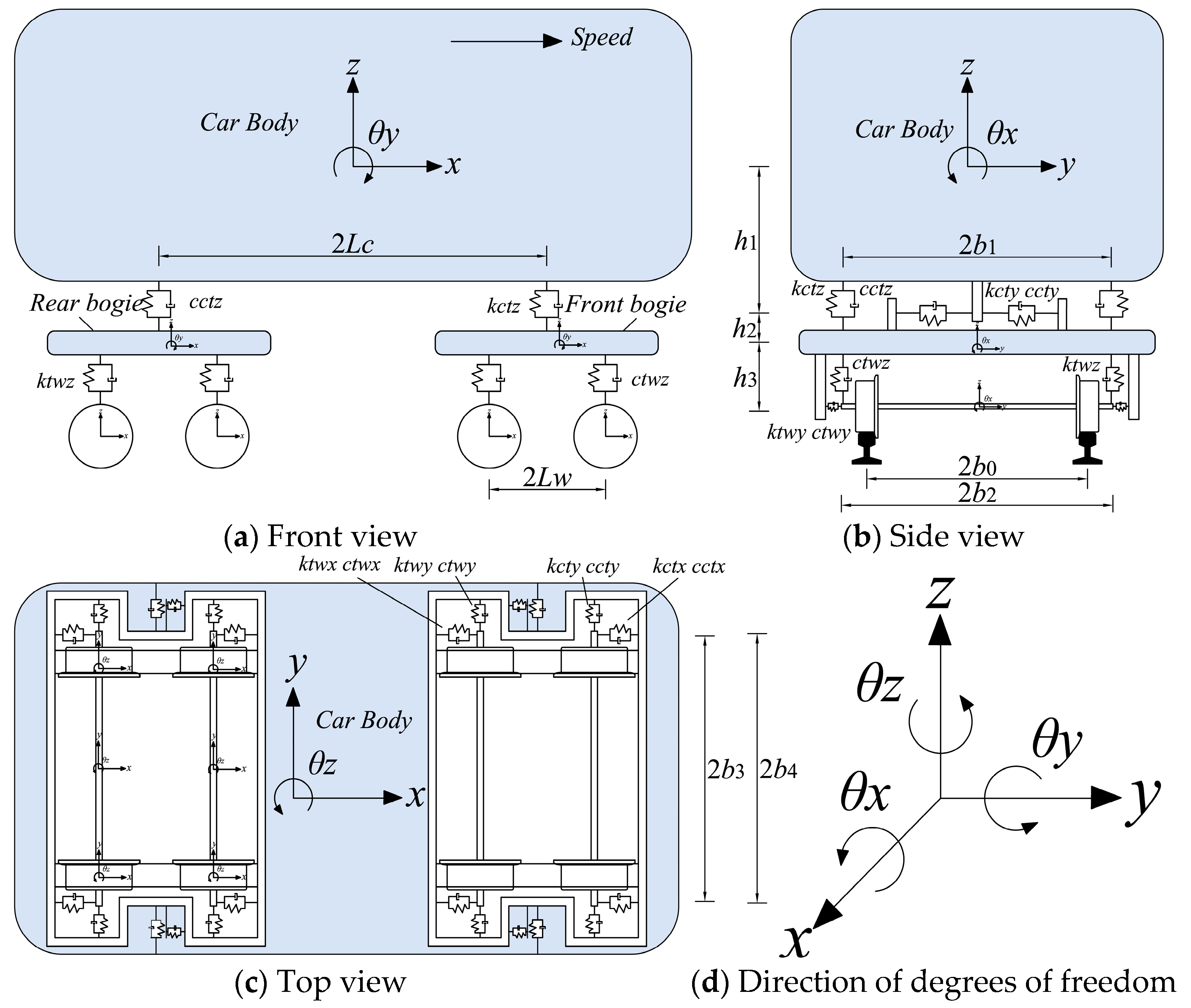
2.1. Train Model

The single-section train model is shown in Figure 1. Each carriage consists of four wheelsets, a car body, and two bogies at the front and rear. It is assumed that the car body, wheel pairs and bogies are rigid bodies, and the car body and bogies, and bogies and wheelsets are simulated to be connected by linear spring dampers in longitudinal, lateral and vertical directions [26,28,29]. The car body contains six degrees of freedom, each wheel pair contains five degrees of freedom, and each bogie contains six degrees of freedom. That is, a single-section train model with 38 degrees of freedom is established, and the distribution of degrees of freedom is shown in Table 1.
The subscript symbols c, wi, tf, and bf in Table 1 denote the train body, the i-th wheel set, and the front and rear bogies of the train, respectively. The mass M c c , stiffness Κ c c , and damping matrices C c c of the train are obtained from the multi-rigid body dynamics.

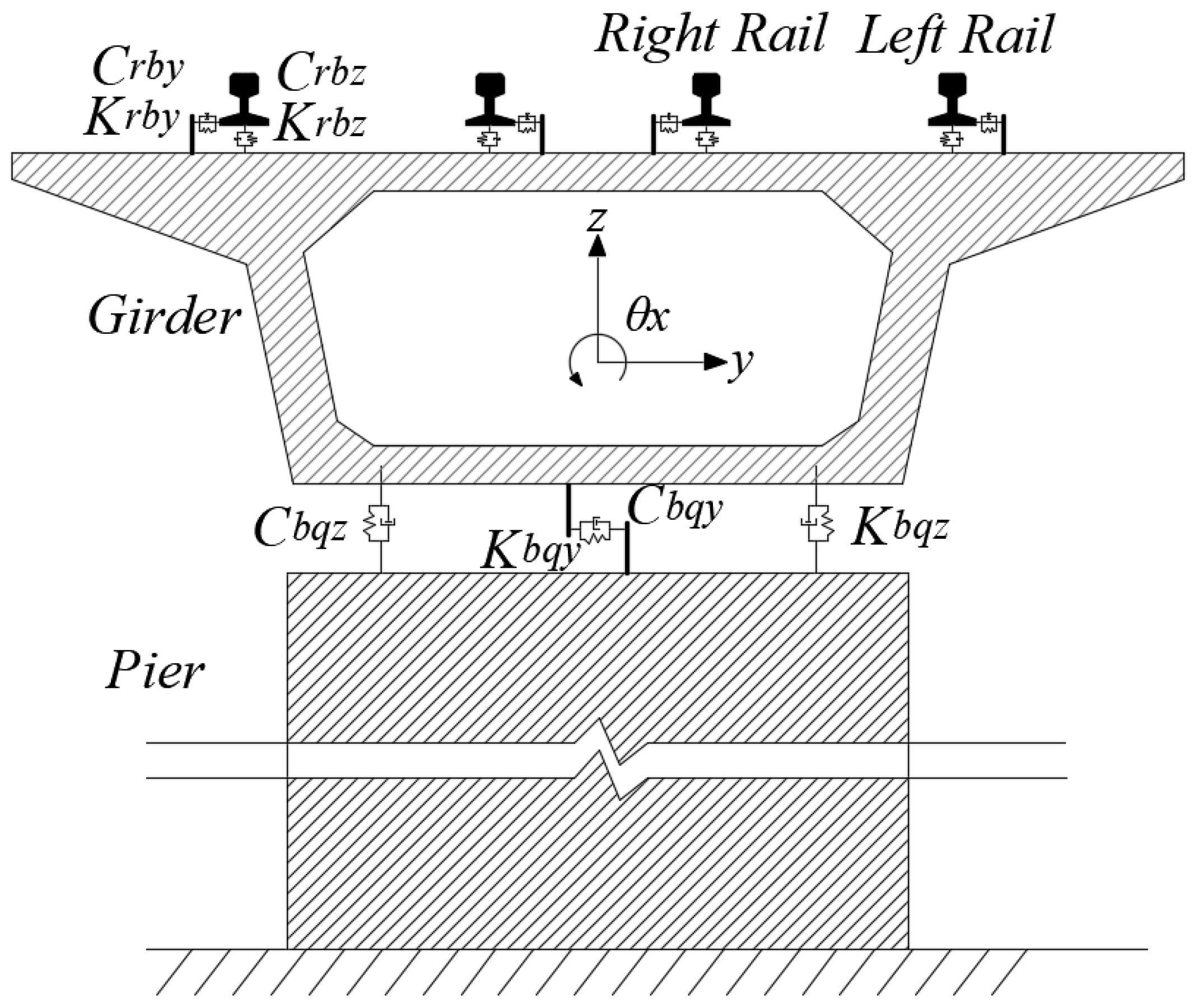
2.2. Track and Bridge Model

This paper takes CRTS Ⅱ slab ballastless track as an example to establish the track model. The track structure is mainly composed of a base, CA mortar layer, track board, elastic fasteners, rails and other components [30,31]. The steel rail is simulated as a beam element, and the track plate and base are both simulated as plate elements. The base is connected to the bridge, the track plate is connected to the base, and the steel rail is connected to the track plate as a linear spring damper, as shown in Figure 2.
The bridge adopts a simply supported concrete box girder at both ends and a concrete pier, as shown in Figure 3. The connection between the steel beam and the steel rail is also considered as a linear spring damper connection. A bridge model is established based on the finite element method, and the pier and beam are simulated as Euler–Bernoulli beam elements. Each element has two nodes, and each node contains six degrees of freedom.
The mass matrix M r r , M b b , stiffness matrix K r r , K b b and damping matrix C r r , C b b of the bridge and track can be easily calculated via the finite element method [32,33]. The damping matrix C b b of the bridge adopts Rayleigh damping, which can be composed of a mass matrix M b b and stiffness matrix K b b in a linear way.
C b b = 2 ω 1 ω 2 ζ ω 1 + ω 2 M b b + 2 ζ ω 1 + ω 2 K b b
where ω 1 , ω 2 denote first-order and second-order natural frequencies (rad) of the bridge structure, respectively, and ζ denotes the bridge damping ratio. Here, it is assumed that the first-order and second-order corresponding bridge damping ratios are equal. Moreover, the stiffness and damping matrices ( K r b , K b r , C r b , C b r ) of the interaction between the track and the bridge are also easily obtained, with the following relationships:
K b r = K r b T , C b r = C r b T

2.3. Rail Irregularity

In reality, when trains pass over bridges, there are irregularities in the running surface of the steel rails, which can be divided into four types: high and low irregularities, track orientation irregularities, horizontal irregularities, and gauge irregularities [34]. In this paper, the low interference rail irregularity power spectral density (PSD) of Germany is used to describe the rail irregularity state of high-speed railways [29,35].
S v ( Ω ) = A v Ω c 2 ( Ω 2 + Ω r 2 ) ( Ω 2 + Ω c 2 ) S a ( Ω ) = A a Ω c 2 ( Ω 2 + Ω r 2 ) ( Ω 2 + Ω c 2 ) S c ( Ω ) = A v b 0 2 Ω c 2 Ω 2 ( Ω 2 + Ω r 2 ) ( Ω 2 + Ω c 2 ) ( Ω 2 + Ω s 2 ) S s ( Ω ) = A g Ω c 2 Ω 2 ( Ω 2 + Ω r 2 ) ( Ω 2 + Ω c 2 ) ( Ω 2 + Ω s 2 )
where, S v ( Ω ) , S a ( Ω ) , S c ( Ω ) , S s ( Ω ) denote the irregularity PSD of the vertical rail profile, rail cross-level, rail alignment and rail distance, respectively m 2 / ( rad / m ) , A v , A a , A g denote the constants of roughness ( m 2 rad / m ) , Ω c , Ω r , Ω s denote the truncation frequency (rad/m), b 0 denotes the half distance between two rails (m), and the corresponding parameters are shown in Table 2.

2.4. Train–Track–Bridge Coupled Vibration

According to the mass matrix, stiffness matrix and damping matrix obtained using the finite element method, multi-rigid body dynamics and other processing methods, based on the energy principle, the train–track–bridge coupled vibration equation can be derived, as shown below:
M c c 0 0 0 M r r 0 0 0 M b b X ¨ c c X ¨ r r X ¨ b b + C c c C c r 0 C r c C r r C r b 0 C b r C b b X ˙ c c X ˙ r r X ˙ b b + K c c K c r 0 K r c K r r K r b 0 K b r K b b X c c X r r X b b = Q c c Q r r 0
where X c c , X r r and X b b denote the displacement vector of the train, rail and bridge, respectively, while Q c c , Q r r denote the load train vector of the train and rail, respectively.

2.5. Equation Solving of System Coupled Vibration

Since the equations of motion are functional equations with respect to time, at present, numerical analysis methods are commonly used, such as the mean acceleration method, linear acceleration method, Wilson-θ method, Newmark’s method, Runge–Kutta method, and Houbolt’s method. In this paper, the MATLAB program solves the system dynamic response based on the Wilson-θ method.
The Wilson-θ method is an improvement on the linear acceleration method, which is one of the simplest and best methods to use, expanding the time step from Δ t to θ Δ t , and unconditionally stabilizing at θ > 1.37 , and the MATLAB program in this paper takes θ = 1.4 . Since M , K , C vary with time, it is necessary to establish M t + θ Δ t , K t + θ Δ t , C t + θ Δ t at each moment. At the moment t, the initial acceleration is calculated from the given initial velocity of the system and the initial displacement using the following equation:
M t q ¨ t + C t q ˙ t + K t q t = Q t
Calculate Q t + θ Δ t at each moment in time according to the linear law of change.
Q t + θ Δ t = Q t + θ ( Q t + Δ t Q t )
Calculate the equivalent stiffness matrix and the equivalent load matrix at time t + θ Δ t , respectively.
K ¯ t + θ Δ t = K t + θ Δ t + 6 θ Δ t 2 M t + θ Δ t + 3 θ Δ t C t + θ Δ t Q ¯ t + θ Δ t = Q t + θ Δ t + 6 q t θ Δ t 2 + 6 q ˙ t θ Δ t + 2 q ¨ t M t + θ Δ t + 3 q t θ Δ t + 2 q ˙ t + θ Δ t q ¨ t 2 C t + θ Δ t
Solve for q t + θ Δ t at each moment using the following equation.
K ¯ t + θ Δ t q t + θ Δ t = Q ¯ t + θ Δ t
Finally, the acceleration, velocity, and displacement responses for each moment can be solved by the following equation:
q ¨ t + Δ t = 6 θ θ Δ t 2 ( q t + θ Δ t q t ) 6 θ 2 Δ t q ˙ t + 1 3 θ q ¨ t q ˙ t + Δ t = q ˙ t + Δ t 2 q ¨ t + Δ t + q ¨ t q t + Δ t = q t + Δ t q ˙ t + Δ t 2 6 q ¨ t + Δ t + 2 q ¨ t

3. Analysis and Calculation Parameters

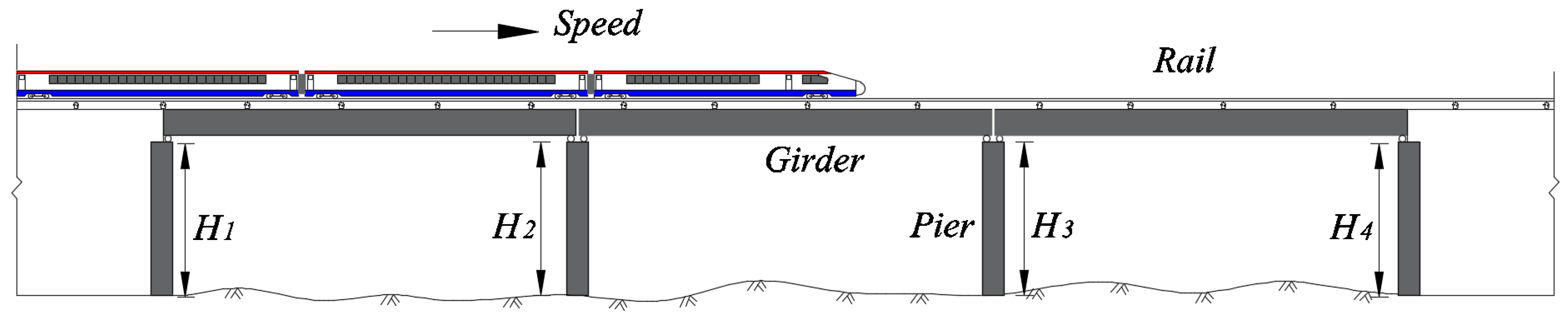
3.1. Research Scenario

In order to analyze the influence of unequal-height piers on the dynamic characteristics of high-speed train–track–bridge coupling systems, this paper takes a three span simply supported box girder bridge as an example. As shown in Figure 4, the train speed is 350 km/h, the span length is 32 m, and the bridge consists of a round-ended solid pier with a height of 8 m and a cross-sectional area of 7.6 m 2 , and a C35 cast-in-place concrete pier shaft. The structural damping ratio is 3%. The corresponding parameters of the bridge are shown in Table 3, and the track and wheel set parameters are detailed in the Ref. [36]. The train formation is: motor train + trailer × 6 + motor train. The corresponding parameters of the high-speed train and trailer are based on the German ICE3 train set parameters, as detailed in Ref. [37].

3.2. Pier Height Working Condition

In order to fully analyze the influence of unequal-height piers on the dynamic characteristics of a high-speed train–track–bridge coupling system, the equal-height pier condition is set, and two unequal-height pier conditions are considered, namely gradually increasing unequal-height piers and sharply increasing unequal-height piers. The pier height parameters are shown in Table 4 below:

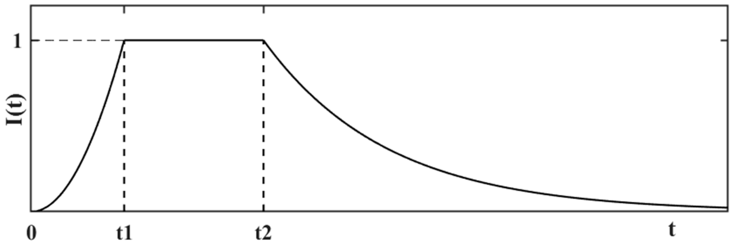
3.3. Earthquake Excitation Model

For high-speed railways, earthquakes not only directly affect the operation of high-speed trains and pose a threat of derailment to passengers, but also affect the construction and maintenance of high-speed railway lines. Once an earthquake occurs, it causes serious damage to infrastructures such as tracks and viaducts, greatly increasing maintenance costs and operational losses. Based on the above situation, it is of great significance to consider the seismic influence in vehicle–bridge vibration analysis.
Due to the limited number of existing seismic records, it is not enough to solely study the dynamic response of the system under earthquakes using existing records. Therefore, this article uses artificial seismic waves as seismic excitations. The mathematical model of seismic waves is simulated by using trigonometric series synthesis [35], and the artificial seismic wave is synthesized by using the simulated standard response spectrum. The acceleration equation of seismic ground motion is expressed in Equation (10):
q ¨ ( t ) = I ( t ) k = 1 n A ( ω k ) sin ( ω k + φ k )
I ( t ) = t t 1 2 0 t t 1 1 t 1 t t 2 e c ( t t 2 ) t 2 t
A ( ω k ) = 4 S g ( ω ) Δ ω
ω k = ω l + k 1 2 Δ ω Δ ω = ω u ω l n , k = 1 , 2 , n
where I ( t ) denotes the intensity envelope function, which describes the process of earthquakes from appearance, enhancement, stationarity, and weakening, as shown in Figure 5. The values of each parameter of the intensity envelope function are referred to in Ref. [35]. c, A ( ω k ) , S g ( ω ) , ω k , φ k , ω u , ω l denote the attenuation coefficient of the weakening section, the amplitude of corresponding ω k , the spectral density function of ground motion acceleration power, the k-th frequency, the random phase angle evenly distributed and mutually independent within [ 0   ,   2 π ] , and the upper and lower limits of frequency, respectively.
In this paper, the ground vibration power spectral density function model adopts the Clough–Penzien model that considers the low-frequency components.
S g ( ω ) = ω g 4 + 4 ζ g 4 ω g 2 ω 2 ( ω g 2 ω 2 ) 2 + 4 ζ g 2 ω g 2 ω 2 × ω 4 ( ω f 2 ω 2 ) 2 + 4 ζ f 2 ω f 2 ω 2 S 0
where ω g , ζ g denote the site excellence frequency and site damping ratio, respectively, ω f , ζ f denote the ground filtering parameters for controlling low-frequency components of ground motion, and S 0 denotes the spectral intensity factor, as shown in Table 5.
The site categories are divided into four classes, Ⅰ, Ⅱ, Ⅲ and Ⅳ, according to the soil layer where the structure is located.
(1)
Class I site soil: rocky, compact gravelly soil.
(2)
Class Ⅱ site soil: medium-dense, loose gravel soil, dense, medium-dense gravel, coarse and medium sand; clayey soil with foundation soil with a permissible bearing capacity σ 0 > 150 kPa.
(3)
Class Ⅲ site soil: loose gravel, coarse and medium sand, dense and medium-dense fine and silty sand, clayey soil with a permissible bearing capacity [σ0] ≤ 150 kPa and fill soil with σ 0 ≥ 130 kPa.
(4)
Class Ⅳ site soil: silty soil, loose fine and chalky sand, recently deposited clayey soil; fill with foundation soil with an allowable bearing capacity σ 0 < 130 kPa.
Taking a Class II site with an eight-degree fortification and a 0.1 g seismic acceleration as an example, the design earthquake group is set as the second group. The seismic excitation adopts a combination of longitudinal, transverse, and vertical earthquakes E x + E y + 0.65 E x .

4. Dynamic Response of the System

This paper conducted a study on the influence of three pier height working conditions on the coupled vibration response and running safety of the vehicle bridge system at five speeds of 150, 200, 250, 300, and 350 km/h. The constant height pier working conditions were selected to explore the influence of vehicle speed and seismic action on the dynamic response of the high-speed train–track–bridge system.

4.1. Validation of the System

In order to verify the reliability and accuracy of the train–track–bridge coupled vibration system model established in this paper, an example of Ref. [38] is used for the reliability analysis, the parameters of the bridge and the train are set to be the same as those in Ref. [38], and the train is set to run at a speed of 240 km/h. Comparing the vertical displacement of the bridge spans, as can be seen in Figure 6, the vertical time-dependent response of the bridge spans obtained via the two models are very close and almost overlap, which means that the train–track–bridge coupled vibration system model is reliable.

4.2. Train Running Safety Indicators

4.2.1. Derailment Coefficient

French scientist Nadal first began to study the wheel climbing phenomenon, and in 1896, according to the climbing wheel climbing tendency of static equilibrium conditions, deduced the minimum derailment coefficient Q/P [39]. The wheel–rail contact diagram as shown in Figure 7.
Q P = tan α μ 1 + μ tan α
where Q denotes the wheel rail lateral force, P denotes the wheel weight, α denotes the angle between tangent line and horizontal line at the contact point of wheel and rail, that is, rim contact angle; and μ denotes the coefficient of friction between wheel rim and rail side.
The derailment factor varies from country to country. According to Chinese standard TB10761-2013 [40], the derailment factor should meet the following requirements:
Q / P 0.8 Allowable   limit Q / P 1.0 Danger   limit

4.2.2. Rate of Wheel Load Reduction

In addition to the derailment coefficient, people also use the rate of wheel load reduction to determine the train running safety. When the wheels are substantially loaded down, that is, the vertical force on the wheels and rail is very small, the corresponding lateral force on the wheels and rail is often very small, and due to the impact of measurement error, it is difficult to calculate the derailment coefficient, especially when the wheel and rail are detached, which provides the derailment coefficient to assess the train running safety, addressing this serious problem.
Therefore, the increase in the rate of wheel load reduction can be used to comprehensively and effectively assess the derailment stability of the train’s running. The rate of wheel load reduction is defined as the ratio of the wheel weight reduction Δ P on the reduced side to the average static wheel weight P ¯ of the wheelset. The rate of wheel load reduction standard stipulated by China is as follows [41]:
Δ P / P ¯ 0.65 First   limit ,   eligibility   criteria Δ P / P ¯ 0.6 Sec ond   limit ,   increased   safety   margin   criteria

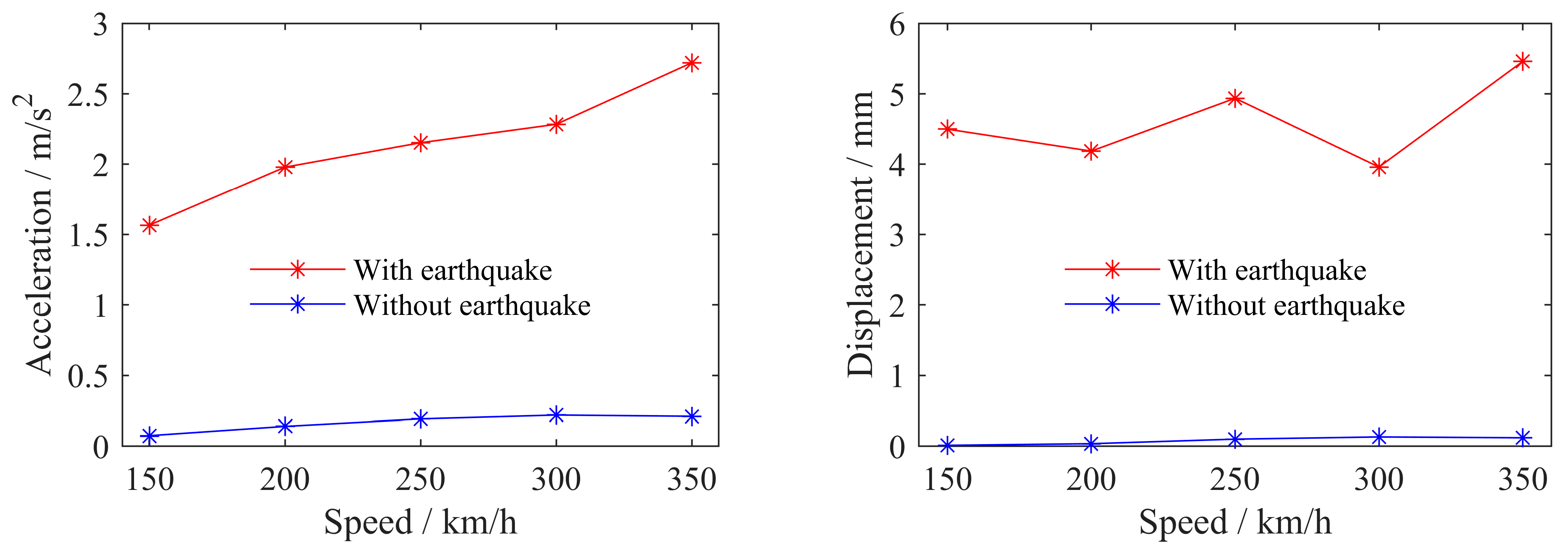
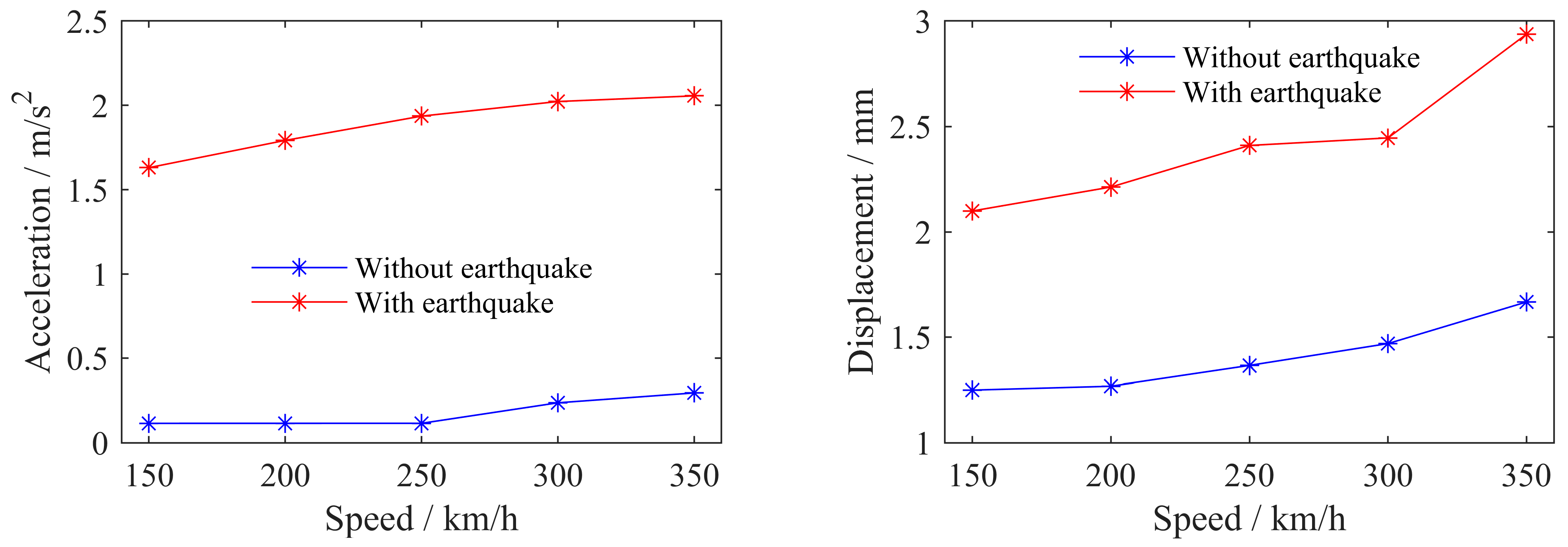
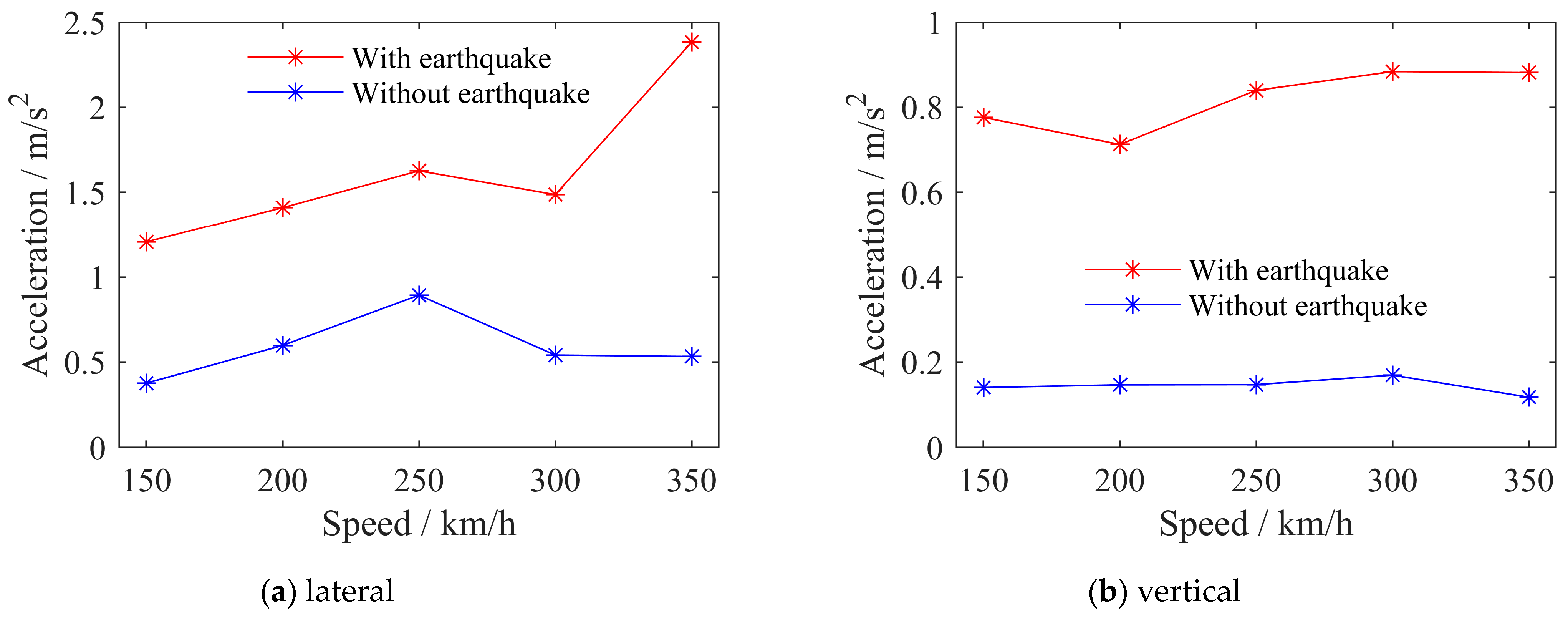
4.3. The Influence of Train Speed on System Dynamic Response

We compare the dynamic response of the system under no seismic excitation with that under seismic excitation, and analyze the influence of an earthquake on the dynamic response of the train–track–bridge system. The train passed over the bridge at speeds of 150, 200, 250, 300, and 350 km/h, respectively, and we recorded the peak dynamic response of the system, as shown in the following figures.
From Figure 8 and Figure 9, it can be seen that seismic excitation has a significant impact on the dynamic response of bridges, with a particularly prominent impact on the acceleration response. The lateral dynamic response of the bridge increases more than the vertical dynamic response. This is because when there is no earthquake, the lateral dynamic response of the train mainly comes from the lateral track’s irregularity, and the vertical dynamic response mainly comes from the train’s gravity. The seismic excitation is input according to the vertical seismic wave strength, which is 0.65 times the horizontal seismic wave strength. Therefore, the seismic excitation has a more intense and sensitive impact on the lateral dynamic response of the bridge than the vertical dynamic response, and under earthquake excitation, some responses exceed the safety index limit, seriously reducing the smoothness and safety of the train. Overall, the dynamic response of the bridge increases with the increase in vehicle speed.
From Figure 10, it can be seen that the train response generally increases with the increase in operating speed, and the lateral response is more affected by seismic excitation than the vertical response, for the same reason as the above bridge response influence law. From Figure 11, it can be seen that under seismic excitation, the wheel rail load reduction rate and derailment coefficient of trains generally increase with the increase in vehicle speed. When the operating speed is 350 km/h, the two safety indicators of trains approach the limit values [42]. When the seismic acceleration is greater, the vehicle speed is faster, and the bridge structure is more flexible, the risk of train derailment will greatly increase, and the safety and comfort of trains will be greatly reduced.

4.4. The Influence of Pier Height on System Dynamic Response

This paper only analyzes the influence of unequal pier heights on the dynamic response and running safety of the high-speed train–track–bridge system under seismic excitation when the train passes over the bridge at a speed of 300 km/h. The first- to fourth-order natural frequencies of the bridge as shown in Table 6.
The working conditions of the bridge piers are shown in Table 4 in Section 3.2. From Figure 12, it can be seen that compared to equal-height piers, the peak lateral dynamic response of bridges with unequal-height piers (gradually increasing) decreases, while the peak vertical dynamic response of bridges increases. The peak lateral dynamic response of bridges with unequal-height piers (Sharply increasing) increases sharply, while the peak vertical dynamic response of bridges decreases. From Figure 13, it can be seen that compared to equal-height piers, the peak lateral dynamic response of trains with unequal-height piers (gradually increasing) decreases, which is beneficial for stabilizing the vehicle body. The peak lateral dynamic response of trains with unequal-height piers (sharply increasing) increases sharply, seriously reducing passenger comfort. Moreover, the vertical dynamic response of trains under both unequal-height pier conditions increases, and the safety indicators of equal-height piers are significantly better than those under the two unequal-height pier conditions. From the data in the above figures, it can be concluded that considering the comfort and safety of the train, the optimal choice is to design equal-height bridge piers, followed by gradually increasing pier heights, and avoiding steep increases in pier heights.

5. Conclusions

In this study, based on the finite element method and multi-body dynamics method, a high-speed train–track–bridge coupling system model was established. Calculation and analysis were conducted via programming to explore the influence of unequal-height piers on the dynamic response of a high-speed railway vehicle bridge system. The following conclusion was obtained:
(1)
The dynamic response of the system and the safety index of the train generally increase with the increase in the train running speed.
(2)
Under seismic excitation, the dynamic response of the system is significantly increased, and the lateral dynamic response of the system is more affected by seismic excitation than the vertical response.
(3)
Compared to equal-height piers, the peak lateral dynamic response of the system with unequal-height piers (gradually increasing) decreases, which is beneficial for stabilizing the vehicle body. The peak lateral dynamic response of the system with unequal-height piers (steep increase in pier height) increases sharply, seriously reducing passenger comfort.
(4)
The vertical dynamic response of trains under two unequal-height pier conditions increases, and the safety indicators of equal-height piers are significantly better than the two unequal-height pier conditions. The recommended design is the optimal choice for equal-height bridge piers, followed by gradually increasing pier heights, and avoiding steep increases in pier heights.

Author Contributions

Data curation, Z.Z., H.Z., H.H., P.Z. and F.T.; Writing—original draft, Y.Z.; Writing—review & editing, L.J. and P.X. All authors have read and agreed to the published version of the manuscript.

Funding

This research work was jointly supported by the China Railway Corporation Limited Science and technology research and development program (2022-major-17), Science and Technology Research and Development Program Project of China railway group limited (2020-Key-02), the National Natural Science Foundation of China (Grant No. 11972379), the Hunan Natural Science Foundation Science and Education Joint Fund Project 2022JJ60109, Hunan Science Fund for Distinguished Young Scholars (2021JJ10061).

Data Availability Statement

Underlying research materials related to this paper can be accessed by requesting from the corresponding author.

Conflicts of Interest

The authors declare no conflict to interest.

References

  1. Souza, E.F.; Bragança, C.; Meixedo, A.; Ribeiro, D.; Bittencourt, T.N.; Carvalho, H. Drive-by Methodologies Applied to Railway Infrastructure Subsystems: A Literature Review—Part I: Bridges and Viaducts. Appl. Sci. 2023, 13, 6940. [Google Scholar] [CrossRef]
  2. Arvidsson, T.; Andersson, A.; Karoumi, R. International journal of rail transportation train running safety on non-ballasted bridges train running safety on non-ballasted bridges. Int. J. Rail Transp. 2019, 7, 1–22. [Google Scholar] [CrossRef]
  3. Zhai, W.; Han, Z.; Chen, Z.; Ling, L.; Zhu, S. Train–track–bridge dynamic interaction: A state-of-the-art review. Veh. Syst. Dyn. 2019, 57, 984–1027. [Google Scholar] [CrossRef]
  4. Biggs, J.M. Introduction to Structural Dynamics; McGraw-Hill Book Company: New York, NY, USA, 1964; pp. 23–32. [Google Scholar]
  5. Liu, W.K.; Li, S.; Park, H.S. Eighty Years of the Finite Element Method: Birth, Evolution, and Future. Arch. Comput. Methods Eng. 2022, 29, 4431–4453. [Google Scholar] [CrossRef]
  6. Matsuura, A. Dynamic behavior of bridge girder for high speed railway bridge. Q. Rep. RTRI 1979, 20, 70–76. [Google Scholar]
  7. Chu, K.-H.; Dhar Chaman, L.; Garg Vijay, K. Railway-Bridge Impact: Simplified Train and Bridge Model. J. Struct. Div. 1979, 105, 1823–1844. [Google Scholar] [CrossRef]
  8. Dhar, C.L. A method of computing railway bridge impact. Diss. Abstr. Int. 1978, 39-08, 3947. [Google Scholar]
  9. Liu, H.; Wang, P.; Wei, X.; Xiao, J.; Chen, R. Longitudinal Seismic Response of Continuously Welded Track on Railway Arch Bridges. Appl. Sci. 2018, 8, 775. [Google Scholar] [CrossRef]
  10. Zhao, H.; Wei, B.; Jiang, L.; Xiang, P.; Zhang, X.; Ma, H.; Xu, S.; Wang, L.; Wu, H.; Xie, X. A velocity-related running safety assessment index in seismic design for railway bridge. Mech. Syst. Signal Process. 2023, 198, 110305. [Google Scholar] [CrossRef]
  11. Yang, Y.B.; Wu, Y.S. Dynamic stability of trains moving over bridges shaken by earthquakes. J. Sound Vib. 2002, 258, 65–94. [Google Scholar] [CrossRef]
  12. Hujun, L.; Xiaozhen, L.; Yan, Z. Train running safety analysis of high-pier rigid frame bridge under earthquake action. In Proceedings of the 9th International Conference on Structural Dynamics, EURODYN 2014, Porto, Portugal, 30 June 2014; pp. 1267–1272. [Google Scholar]
  13. Xiang, P.; Ma, H.; Zhao, H.; Jiang, L.; Xu, S.; Liu, X. Safety analysis of train-track-bridge coupled braking system under earthquake. Structures 2023, 53, 1519–1529. [Google Scholar] [CrossRef]
  14. Xiang, P.; Huang, W.; Jiang, L.Z.; Lu, D.G.; Liu, X.; Zhang, Q. Investigations on the influence of prestressed concrete creep on train-track-bridge system. Constr. Build. Mater. 2021, 293, 123504. [Google Scholar] [CrossRef]
  15. Zeng, Y.; Zheng, H.; Jiang, Y.; Ran, J.; He, X. Modal Analysis of a Steel Truss Girder Cable-Stayed Bridge with Single Tower and Single Cable Plane. Appl. Sci. 2022, 12, 7627. [Google Scholar] [CrossRef]
  16. Han, Y.; Xia, H.; Guo, W.-W. Dynamic response of cable-stayed bridge to running trains and earthquakes. Eng. Mech. 2006, 23, 93. [Google Scholar]
  17. Guo, J.; Zhong, J.; Dang, X.; Yuan, W. Seismic Responses of a Cable-Stayed Bridge with Consideration of Uniform Temperature Load. Appl. Sci. 2016, 6, 408. [Google Scholar] [CrossRef]
  18. Variyavwala, J.P.; Desai, A.K. Evaluation of Train Running Safety on Railway Cable-Stayed Bridge During Seismic Excitation. Int. J. Struct. Stab. Dyn. 2023, 23, 2350066. [Google Scholar] [CrossRef]
  19. Zhai, W.; Wang, S. Influence of bridge structure stiffness on the dynamic performance of high-speed train-track-bridge coupled system. Zhongguo Tiedao Kexue/China Railw. Sci. 2012, 33, 19–26. [Google Scholar] [CrossRef]
  20. Chao, C.; Liang, L.; Zhai, W. Dynamic Response of High-Speed Train Subjected to Stiffness Degradation of Simply Supported Bridge. In Proceedings of the 2nd International Conference on Rail Transportation, ICRT 2021, Chengdu, China, 5–6 July 2021; pp. 134–145. [Google Scholar]
  21. Fan, X.; Liu, L.; Wang, X.; Cao, J.; Cheng, W. Vibration Response Analysis of Overhead System Regarding Train-Track-Bridge Dynamic Interaction. Appl. Sci. 2022, 12, 9053. [Google Scholar] [CrossRef]
  22. Chen, Z.; Zhai, W.; Cai, C.; Sun, Y. Safety threshold of high-speed railway pier settlement based on train-track-bridge dynamic interaction. Sci. China Technol. Sci. 2015, 58, 202–210. [Google Scholar] [CrossRef]
  23. Chen, Z.; Zhai, W.; Tian, G. Study on the safe value of multi-pier settlement for simply supported girder bridges in high-speed railways. Struct. Infrastruct. Eng. 2018, 14, 400–410. [Google Scholar] [CrossRef]
  24. Chen, Z.; Zhai, W.; Yin, Q. Analysis of structural stresses of tracks and vehicle dynamic responses in traintrackbridge system with pier settlement. Proc. Inst. Mech. Eng. Part F J. Rail Rapid Transit 2018, 232, 421–434. [Google Scholar] [CrossRef]
  25. Zhang, X.; Shan, Y.; Yang, X. Effect of Bridge-Pier Differential Settlement on the Dynamic Response of a High-Speed Railway Train-Track-Bridge System. Math. Probl. Eng. 2017, 2017, 8960628. [Google Scholar] [CrossRef]
  26. Gou, H.; Liu, C.; Hua, H.; Bao, Y.; Pu, Q. Mapping relationship between dynamic responses of high-speed trains and additional bridge deformations. JVC/J. Vib. Control 2021, 27, 1051–1062. [Google Scholar] [CrossRef]
  27. Feng, Y.-L.; Jiang, L.-Z.; Chen, M.-C.; Zhou, W.-B.; Liu, X.; Zhang, Y.-T. Deformation compatibility relationship of track interlayer with uneven settlement of side pier of continuous girder bridge and its dynamic application. Gongcheng Lixue/Eng. Mech. 2021, 38, 179–190. [Google Scholar] [CrossRef]
  28. Xu, L.; Yu, Z.; Shan, Z. Numerical simulation for traintrackbridge dynamic interaction considering damage constitutive relation of concrete tracks. Arch. Civ. Mech. Eng. 2021, 21, 116. [Google Scholar] [CrossRef]
  29. Jiang, L.; Liu, X.; Xiang, P.; Zhou, W. Train-bridge system dynamics analysis with uncertain parameters based on new point estimate method. Eng. Struct. 2019, 199, 109454. [Google Scholar] [CrossRef]
  30. Zhai, W. Development of vehicle-track coupled dynamics theory and engineering practice. Kexue Tongbao/Chin. Sci. Bull. 2022, 67, 3793–3807. [Google Scholar] [CrossRef]
  31. Xu, L.; Lu, T. Influence of the finite element type of the sleeper on vehicle-track interaction: A numerical study. Veh. Syst. Dyn. 2021, 59, 1533–1556. [Google Scholar] [CrossRef]
  32. Chen, Y.; Huang, X.-Q.; Ma, Y.-F. Coupling vibration of vehicle-bridge system. Appl. Math. Mech. 2004, 25, 390–395. [Google Scholar] [CrossRef]
  33. Li, X.-Z.; Zhang, L.-M.; Zhang, J. State-of-the-art review and trend of studies on coupling vibration for vehicle and highway bridge system. Gongcheng Lixue/Eng. Mech. 2008, 25, 230–240. [Google Scholar]
  34. Zhao, H.; Wei, B.; Guo, P.; Tan, J.; Xiang, P.; Jiang, L.; Fu, W.; Liu, X. Random analysis of train-bridge coupled system under non-uniform ground motion. Adv. Struct. Eng. 2023. [Google Scholar] [CrossRef]
  35. Gou, H.; Liu, C.; Xie, R.; Bao, Y.; Zhao, L.; Pu, Q. Running safety of high-speed train on deformed railway bridges with interlayer connection failure. Steel Compos. Struct. 2021, 39, 261–274. [Google Scholar] [CrossRef]
  36. Yu, Z.-w.; Mao, J.-f. Probability analysis of train-track-bridge interactions using a random wheel/rail contact model. Eng. Struct. 2017, 144, 120–138. [Google Scholar] [CrossRef]
  37. Zeng, Q.; Dimitrakopoulos, E.G. Seismic response analysis of an interacting curved bridge-train system under frequent earthquakes. Earthq. Eng. Struct. Dyn. 2016, 45, 1129–1148. [Google Scholar] [CrossRef]
  38. Mao, J.; Yu, Z.; Xiao, Y.; Jin, C.; Bai, Y. Random dynamic analysis of a train-bridge coupled system involving random system parameters based on probability density evolution method. Probabilistic Eng. Mech. 2016, 46, 48–61. [Google Scholar] [CrossRef]
  39. Zeng, Q.; Dimitrakopoulos, E.G. Derailment mechanism of trains running over bridges during strong earthquakes. Procedia Eng. 2017, 199, 2633–2638. [Google Scholar] [CrossRef]
  40. China, S. Technical Regulations for Dynamic Acceptance for High-Speed Railways Construction; Standards Press of China: Beijing, China, 2013. [Google Scholar]
  41. Zhao, H.; Wei, B.; Jiang, L.; Xiang, P. Seismic running safety assessment for stochastic vibration of train–bridge coupled system. Arch. Civ. Mech. Eng. 2022, 22, 180. [Google Scholar] [CrossRef]
  42. Luo, X. Study on methodology for running safety assessment of trains in seismic design of railway structures. Soil Dyn. Earthq. Eng. 2005, 25, 79–91. [Google Scholar] [CrossRef]
Figure 1. Single train model.
Applsci 13 10271 g001
Figure 2. Cross section view of track model.
Applsci 13 10271 g002
Figure 3. Cross section view of bridge model.
Applsci 13 10271 g003
Figure 4. High-speed train–track–bridge coupled system.
Applsci 13 10271 g004
Figure 5. Strength envelope function diagram.
Applsci 13 10271 g005
Figure 6. Model validation with the example in Ref. [38].
Applsci 13 10271 g006
Figure 7. Wheel–rail contact diagram.
Applsci 13 10271 g007
Figure 8. Peak lateral response of bridge midspan.
Applsci 13 10271 g008
Figure 9. Peak vertical response of bridge midspan.
Applsci 13 10271 g009
Figure 10. Peak train acceleration.
Applsci 13 10271 g010
Figure 11. Train safety index.
Applsci 13 10271 g011
Figure 12. Peak response of bridge midspan.
Applsci 13 10271 g012
Figure 13. Train dynamic response.
Applsci 13 10271 g013
Table 1. Distribution of 38 degrees of freedom for a single train section.
VerticalLongitudinalLateralYawRollPitch
Car body z c x c y c θ z c θ x c θ y c
Front bogie z t f x t f y t f θ z t f θ x t f θ y t f
Rear bogie z t b x t b y t b θ z t b θ x t b θ y t b
First wheel set z w 1 x w 1 y w 1 θ z w 1 θ x w 1 -
Second wheel set z w 2 x w 2 y w 2 θ z w 2 θ x w 2 -
Third wheel set z w 3 x w 3 y w 3 θ z w 3 θ x w 3 -
Fourth wheel-set z w 4 x w 4 y w 4 θ z w 4 θ x w 4 -
Table 2. Parameters of PSD of rail irregularity.
Ω c Ω r Ω s A g A v A a
0.82640.02060.438 5.32 × 10 8 2.119 × 10 7 4.032 × 10 7
Table 3. Some parameters of the bridge.
ParametersDefinitionsValuesUnits
E b Elastic modulus3.45 × 1010 N / m 2
I Mass moment of inertia of cross section12.744 m 4
μ Poisson’s ratio0.2/
m ¯ b Mass per unit length2.972 × 104 kg / m
L e Length of element3.2 m
ζ Damping ratio0.03/
Table 4. Pier height parameters under different working conditions.
Working Condition Type H 1 H 2 H 3 H 4
Equal-height pier (m)8888
Gradually increasing (m)8101214
Sharply increasing (m)881414
Table 5. Seismic PSD parameter values.
ParametersSite Classification
IIIIIIIV
ζ g 0.7280.7750.8220.868
ζ f 0.4110.5571.1402.208
ω g ( rad s - 1 ) 24.76318.65613.4919.848
ω f ( rad s - 1 ) 0.4530.3550.1540.082
S 0 ( cm 2 / s 2 ) (PGA = 0.1 g)11.24115.54622.37031.201
S 0 ( cm 2 / s 2 ) (PGA = 0.2 g)43.02859.51285.598119.304
S 0 ( cm 2 / s 2 ) (PGA = 0.4 g)172.103238.028342.905478.009
Table 6. First- to fourth-order natural frequencies of the bridge.
Working Condition Type1st Modulus2nd Modulus3rd Modulus4th Modulus
Equal-height pier13.18713.30215.80621.443
Gradually increasing10.45210.51812.99815.538
Sharply increasing9.63010.83213.96415.595
Disclaimer/Publisher’s Note: The statements, opinions and data contained in all publications are solely those of the individual author(s) and contributor(s) and not of MDPI and/or the editor(s). MDPI and/or the editor(s) disclaim responsibility for any injury to people or property resulting from any ideas, methods, instructions or products referred to in the content.

