1. Introduction
As an important device in the propulsion systems of deep-sea submersibles, the mechanical seal plays a vital role in the stability, reliability, and safe operation of deep-sea submersibles. In extreme marine environments, the mechanical seal is susceptible to alternating loads whose magnitude and direction vary periodically with time. The periodic intermittent frictional contact problem of the seal face occurs under alternating loads, and a moving heat source is generated on the seal face, resulting in thermal shock. Repeated thermal shocks and the synergy effect of the locally varying contact pressure and friction force cause the failure of the mechanical seal due to the deformation and wear aggravation of the seal face. Therefore, it is necessary to research the deformation of the seal face to establish the coupling deformation characteristics under alternating loads and improve the sealing performance of the mechanical seal.
In the field of fluid seals, many scholars have completed a great deal of work on the deformation of the mechanical seal. For example, Li et al. [
1] studied the deformation of the seal ring based on the finite element method and found that the thermal deformation of the seal ring was larger than that of force deformation. Green et al. [
2] focused on the time-varying effect of the deformation and contact pressure of the seal face during the start–stop stage of the mechanical seal. Brunetiere [
3,
4] and Wen et al. [
5] investigated the influence of the deformation of the seal ring on the performance of the mechanical seal based on the thermal–elasto–hydrodynamic model. Gao et al. [
6,
7] established an axisymmetric model of the mechanical seal and presented that the seal face would appear to form a convergent gap based on the thermal–mechanical coupling effect. Li’s team [
8,
9] established the thermal–structural coupling model of the mechanical seal using finite element software and studied the deformation characteristics of the seal face based on high-speed dry friction. Fan et al. [
10] investigated the coupling deformation of the deep-sea mechanical seal using the separation method, and Chen et al. [
11] used the integral coupling method to investigate the thermal–mechanical coupling characteristics of the mechanical seal ring. Zhou et al. [
12] analyzed the coupling effect of the thermal deformation of the seal face of the mechanical seal based on the finite element method (FEM).
Many researchers have contributed to the deformation characteristics of the mechanical seal face and successfully solved related problems using computational fluid dynamics (CFD). However, there are still some limitations due to the complexity of the problem and many simplified assumptions, and most research is performed in a steady state. There are few studies on the deformation of the mechanical seal face based on marine transient conditions, especially on the deformation characteristics of the seal face under alternating loads. Although some scholars have researched the thermal–mechanical coupling characteristics of the mechanical seal face under alternating loads [
13], they did not consider the effect of thermal deformation. Later, some scholars focused on the thermal–mechanical coupling effect of the seal face [
14]. However, the actual operation state of the mechanical seal under variable working conditions has not been considered, and research on mechanical seals under continuous alternating fluctuation conditions is still relatively scarce.
The authors studied the temperature distribution of the mechanical seal face in the previous work and the temperature distribution presented the alternating transient characteristics under alternating loads [
15]. Based on this mentioned research, to further study the influence of the instantaneous alternating fluctuation of working conditions on the performance of the mechanical seal face, taking the mechanical seal of the submersible as the object, this paper focuses on the study of deformation characteristics of the mechanical seal face under alternating loads. By considering the influence of the transient fluctuation of working conditions and the coupling effect, the thermal–mechanical coupling deformation characteristics of the mechanical seal face under different alternating loads are revealed, and the morphology and wear characteristics of the mechanical seal face are presented based on the pseudo-real test of the mechanical seal under alternating conditions for evaluation. It provides the basis for improving the stability and reliability of the marine mechanical seal under variable working conditions.
3. Results
3.1. Stable Working Conditions
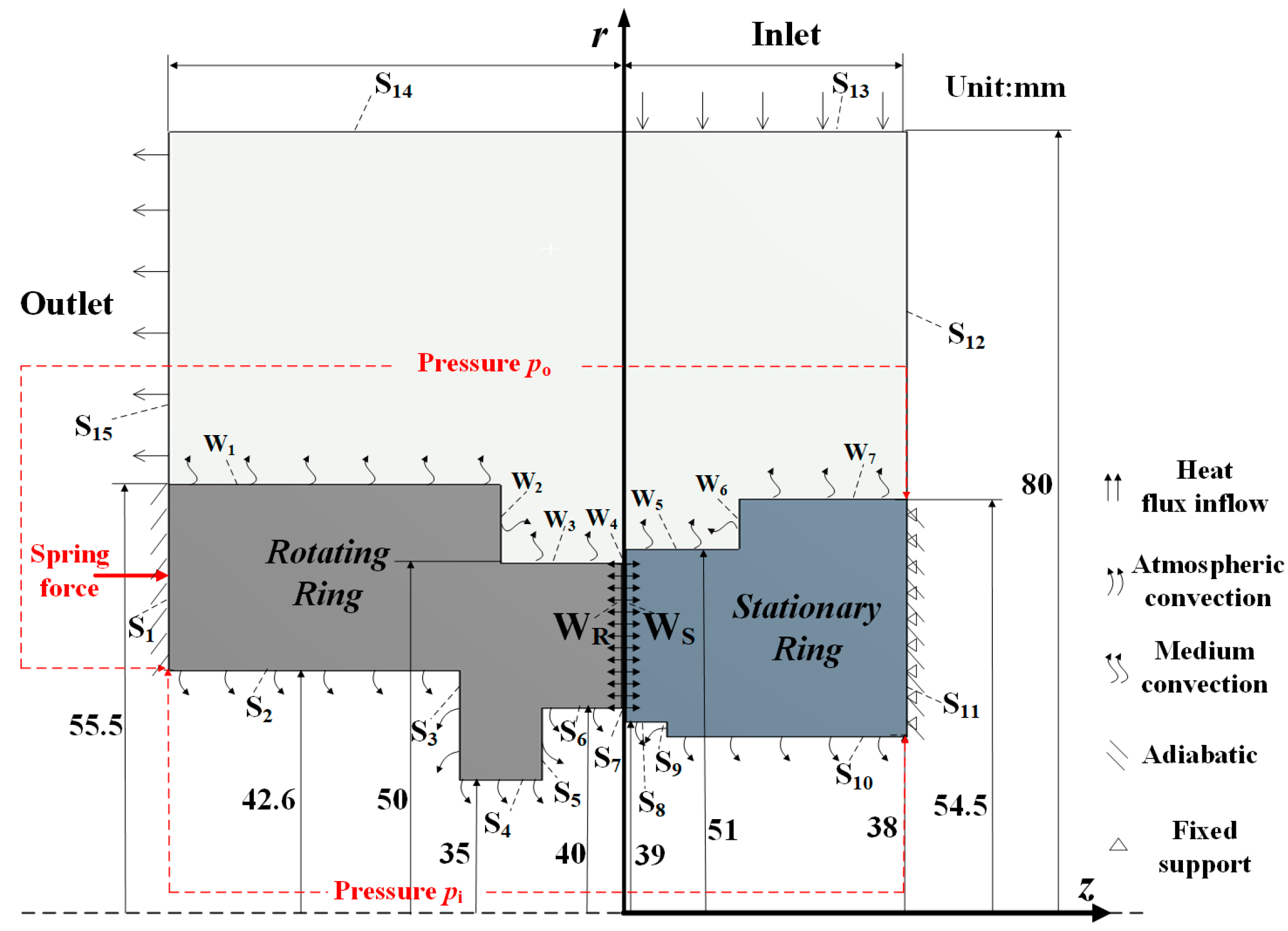
According to the mentioned geometric and numerical model, the steady-state analysis is performed first. Since the axial displacement of the seal ring has a great influence on the seal performance of the mechanical seal, the axial deformation characteristics of the seal ring under different working conditions are the main focus.
Figure 2 presents the contour graph of the axial deformation of the seal ring under the default working parameters (working medium pressure
p = 400 kPa, rotational speed
n = 3600 rpm and
psp = 200 kPa). From
Figure 2, there are similar trends between thermal deformation and thermal–mechanical coupling deformation. Due to the temperature gradient distribution of the seal ring, mainly concentrated near the seal face, and because the temperature gradient along the axial direction is larger than that along the radial direction [
15], the thermal deformation of the seal ring is also mainly concentrated near the seal face. The thermal deformation at the inner diameter of the seal face is greater than that at the outer diameter. This is because the friction heat is mainly concentrated on the inner diameter side of the seal face, and the convective heat transfer coefficient on the inner diameter side of the seal ring is relatively smaller than that on the outer diameter. Under the thermal–mechanical coupling effect, the inner diameter side of the seal face is extruded, while the outer diameter side is in a non-contact state and there is a divergent cone.
In addition, since the thermal conductivity of the rotating ring is smaller than that of the stationary ring, the temperature gradients of the rotating ring are larger than that of the stationary ring. Thus, the thermal deformation of the whole rotating ring is larger than that of the stationary ring. Therefore, the thermal deformation can be diminished by adopting seal ring materials with larger thermal conductivity. In addition, the elastic modulus of the rotating ring is smaller than that of the stationary ring, so the thermal–mechanical coupling deformation of the whole rotating ring is also larger than that of the stationary ring.
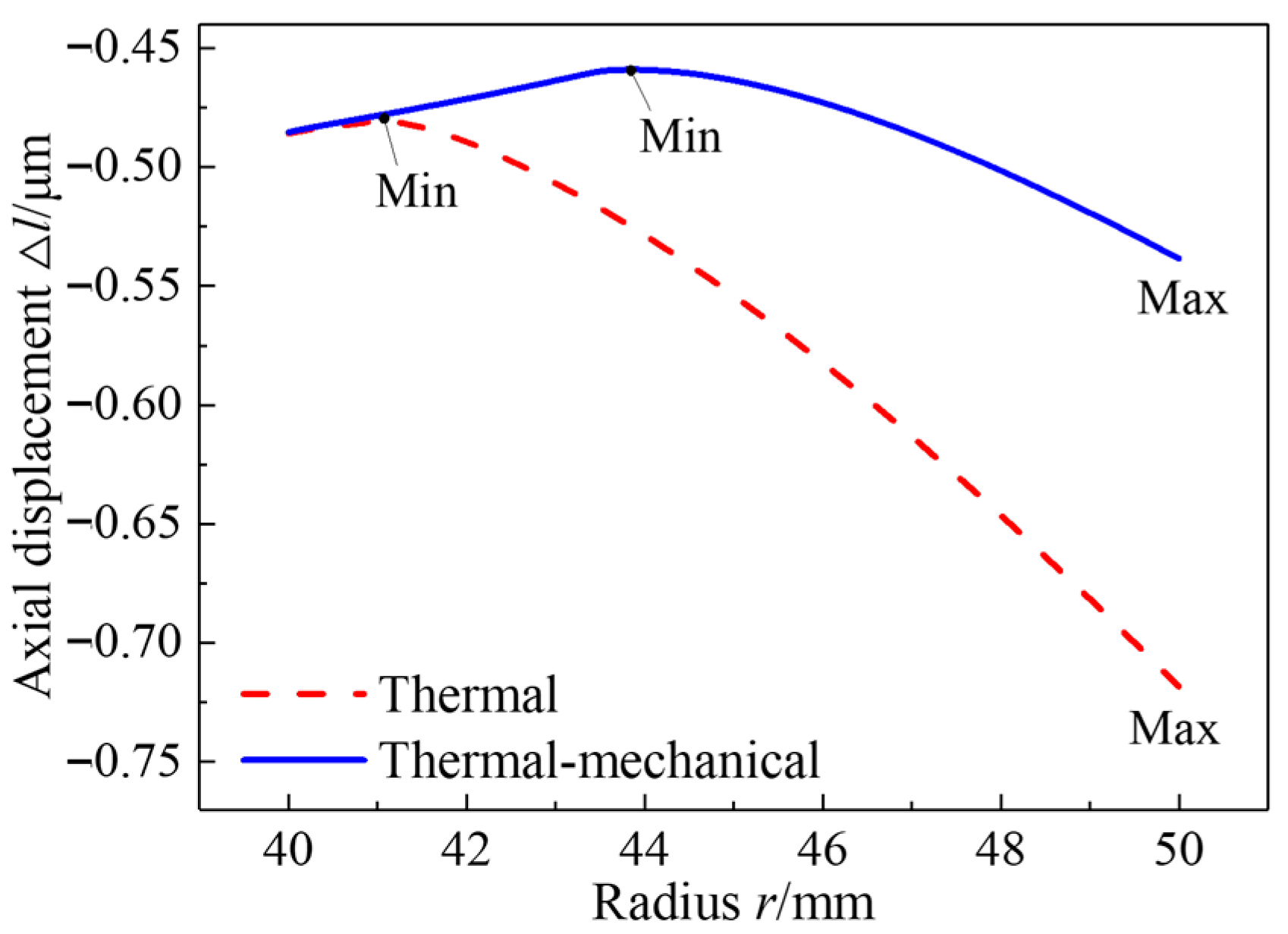
The axial displacement of the end face of the rotating ring along the radial direction under the default working parameters is presented in
Figure 3. The dotted line describes the thermal deformation, and the solid line represents the thermal–mechanical coupling deformation. It can be intuitively seen that the maximum deformation of the end face of the rotating ring occurs at the outer diameter, while the minimum deformation occurs at different locations. Compared with the thermal deformation, the thermal–mechanical coupling deformation is in a convex shape, and the maximum displacement is about 0.538 μm smaller than that of the thermal deformation at about 0.718 μm. In
Figure 3, the minimum deformation of the rotating ring is located near the middle diameter of the end face based on the thermal–mechanical coupling effect. However, the minimum thermal deformation occurs at the place that approaches the inner diameter of the end face. This indicates that the position near the middle diameter of the end face is prone to wear under the thermal–mechanical coupling effect, while the inner diameter region of the end face is prone to wear if the thermal effect is only considered.
Furthermore, the deformation of the end face of the rotating ring is slightly reduced under the thermal–mechanical coupling effect. This is because the thermal deformation caused by the friction heat is dominant in the operation process of the seal ring, and the deformation caused by mechanical force is opposite to the trend of thermal deformation. Under the action of the thermal stress, the extrusion caused by expansion occurs on the seal face, and the expansion at the inner diameter side of the end face of the rotating ring is larger than that at the outer diameter side due to the higher temperature at the inner diameter of the seal face. The larger the temperature gradient of the seal face, the higher the thermal stress of the end face becomes, resulting in seal failure caused by heat crack.
Therefore, it is necessary to minimize the deformation of the seal face by reducing the temperature gradient and the thermal stress of the seal face through reasonable structural design and optimization, to avoid the occurrence of heat cracks in the actual operation of the mechanical seal.
3.1.1. Medium Pressure
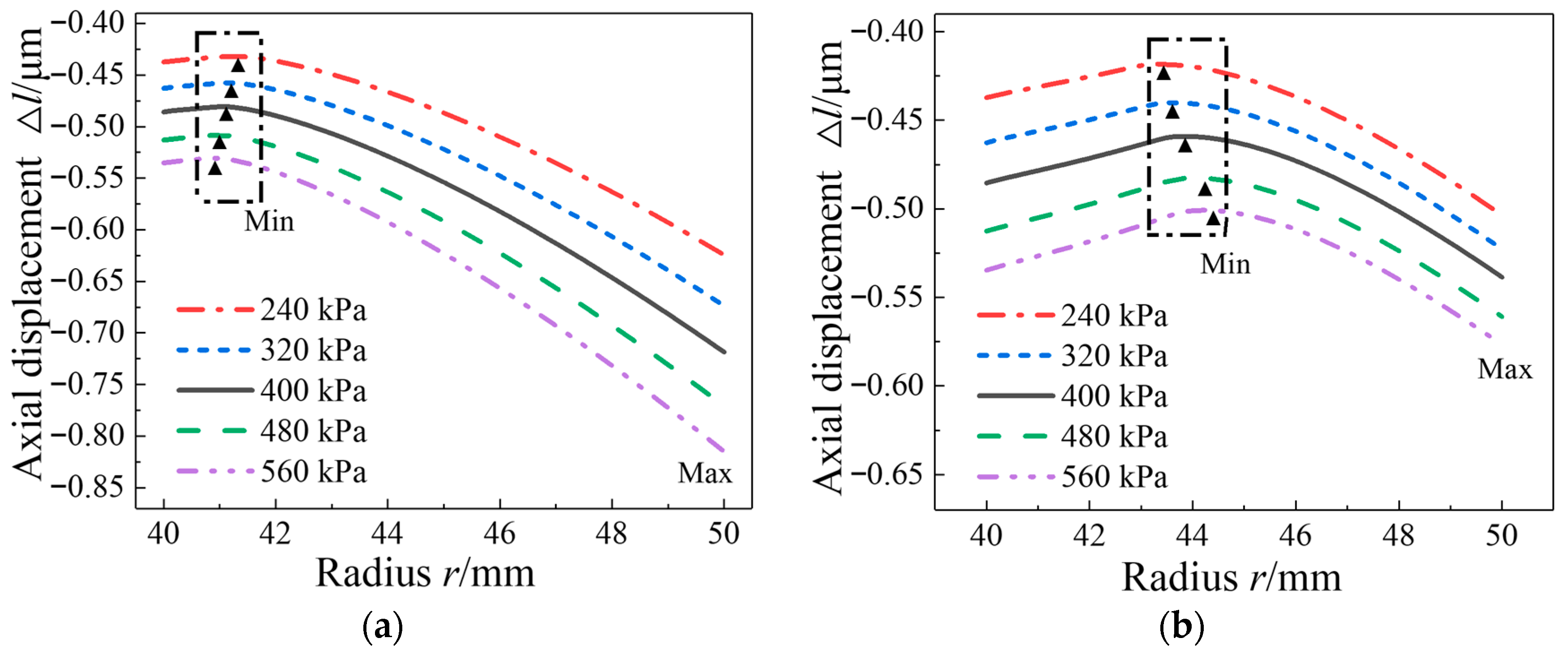
The axial displacement of the end face of the rotating ring under different medium pressures is described in
Figure 4, where the thermal deformation and the thermal–mechanical coupling deformation are all presented. From this figure, it can be known that the axial displacement of the end face of the rotating ring gradually increases with the increase in the medium pressure, and the thermal deformation is also greater than the thermal–mechanical coupling deformation.
As for the thermal deformation shown in
Figure 4a, the minimum displacement is always close to the inner diameter of the end face and it is closer to the inner diameter of the end face with the increase in the medium pressure. This is due to the temperature at the inner diameter being significantly higher than that at the outer diameter, resulting in an uneven distribution of thermal deformation. However, the minimum displacement under the coupling effect is gradually closer to the middle diameter with the increase of the medium pressure, shown in
Figure 4b, indicating that this location is more prone to wear. Meantime, due to the increase of the clamping force from the rotating ring to the stationary ring caused by the increase of the medium pressure, the axial displacement at the outer diameter of the end face under the coupling effect is smaller than that of the thermal deformation.
3.1.2. Rotational Speed
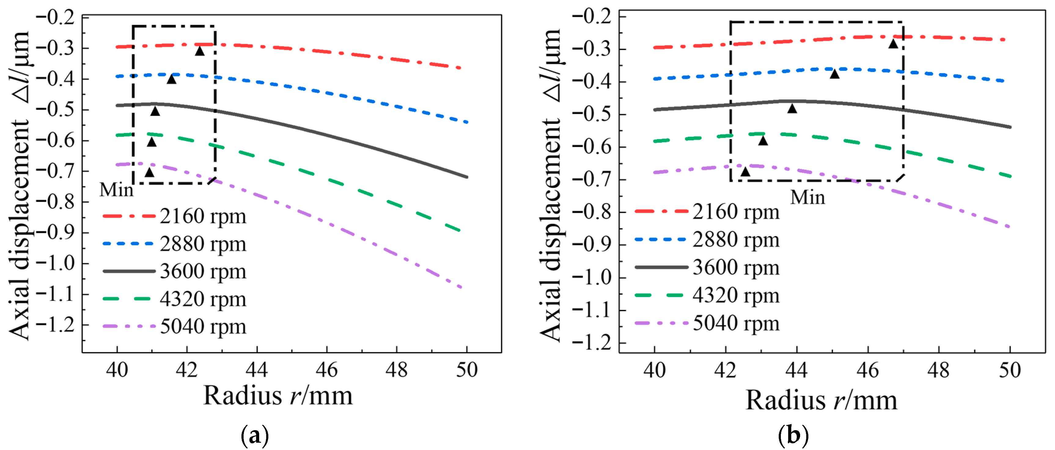
Figure 5 presents the axial displacement of the end face of the rotating ring along the radial direction under different rotational speeds. The deformation of the seal face increases significantly as the rotational speed increases. This is attributed to the increased stress and friction heat on the seal face based on the increased rotational speed. The higher the rotational speed, the larger the taper of the end face caused by the thermal deformation and coupling deformation.
In addition, the thermal deformation of the rotating ring is greater than that of the coupling deformation. When the rotational speed is 5040 rpm, the maximum displacement of the end face during thermal deformation is about 1.1 μm, as shown in
Figure 5a, and larger than the maximum thermal–mechanical coupling displacement which is about 0.85 μm, as shown in
Figure 5b. This indicates that the gap generated at the outer diameter of the end face under thermal deformation is greater than that of the coupling deformation.
For the minimum displacement, the thermal deformation of the rotating ring is closer to the inner diameter of the end face, as shown in
Figure 5a, and the minimum thermal–mechanical coupling deformation shown in
Figure 5b also gradually approaches the inner diameter with the increase in the rotational speed. The main reason is that the temperature difference between the inner and outer diameter of the end face gradually increases with the increase in the rotational speed due to the contact friction at the inner diameter and the strong convective heat transfer at the outer diameter. Thus, the degree of convergence at the inner diameter and the degree of divergence at the outer diameter of the end face are increasing. The inner diameter side of the end face is more prone to extrusion and localized wear based on the increased rotational speed. Therefore, as much as possible, the mechanical seal should not be kept in high-speed operation for a long time. In addition, the damage to the mechanical seal caused by thermal stress and thermal deformation can be reduced by reducing the heat generated by friction and improving the heat transfer effect of the system.
3.2. Alternating Working Conditions
In the research, the alternating working condition is simplified through the Fourier series. If the working condition parameter
f(
t) starts to change periodically from the equilibrium position at the initial moment, the expression of the formula
f(
t) is shown as follows [
15]:
where
Ap is the peak value of the parameter;
Av is the trough value of the parameter;
Γ is the period, s;
t is the time, s.
Based on Formula (5), the alternating speed and alternating medium pressure are designed in the FLUENT software. The above-mentioned default stable operating conditions of the mechanical seal are used in the research; that is, the rotational speed n = 3600 rpm and the medium pressure p = 400 kPa. The dimensionless amplitude M is defined; that is, M = (Ap − f0)/f0, where f0 = 0.5(Ap + Av). The parameter amplitude M is taken as 0.1, 0.2, 0.3, 0.4, and 0.5, respectively, and the periods Γ are 1.6 s, 3.2 s, 4.8 s, 6.4 s, and 8.0 s, respectively.
The temperature distribution of the seal ring in a steady state is applied to the structure of the transient analysis for the coupling deformation of the seal face under alternating loads.
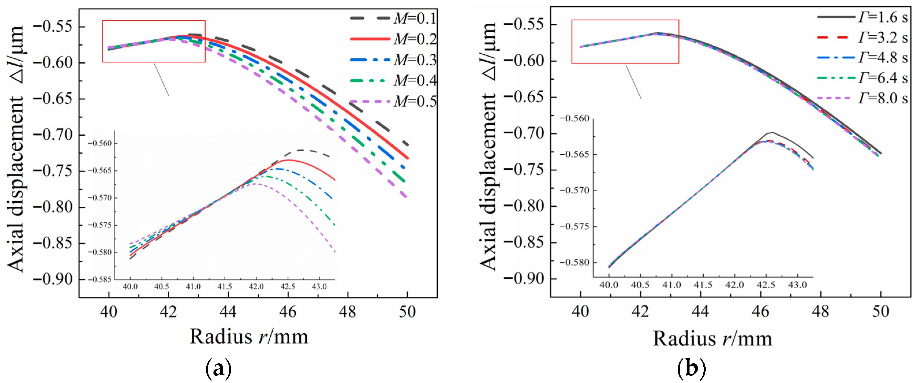
3.2.1. Alternating Medium Pressure
The thermal–mechanical coupling deformation trend of the seal ring under the alternating medium pressure is similar to the results in the stable state shown in
Figure 2. The contact wear occurs at the inner diameter of the seal face and there is a convergent gap at the outer diameter of the seal face. The thermal–mechanical coupling deformation of the whole rotating ring is also larger than that of the stationary ring under the alternating medium pressure due to the smaller elastic modulus of the rotating ring. The axial displacement of the end face of the rotating ring along the radial direction under alternating medium pressure with different amplitudes and periods is described in
Figure 6. From this figure, it can be known that the deformation trends of the end face of the rotating ring based on different amplitudes are close to that of the results with different periods. They are all in a convex shape, and the convex position is closer to the inner diameter of the end face, which may cause this position to be severely worn. This coincides with the results in the stable state shown in
Figure 4.
In
Figure 6, the amplitude and period of the alternating medium pressure have little influence on the coupling deformation of the inner diameter region of the end face of the rotating ring. However, the axial displacement near the outer diameter of the end face increases slightly as the amplitude of the alternating medium pressure increases, as shown in
Figure 6a. This is due to the increased temperature difference between the inner and outer diameters and increased sealing pressure as the increasing amplitude. When the amplitude
M is 0.5, the maximum axial displacement of the end face of the rotating ring |Δ
l| can reach up to 0.789 μm, larger than the stable result of about 0.57 μm. The taper angle on the outer diameter of the end face is also increased under the alternating conditions compared with the stable results.
In
Figure 6b, although the coupling deformation trend of the end face of the rotating ring under different periods is in a similar convex shape to that of results with different amplitudes, there is no obvious difference in the coupling deformation displacement of the end face as the period increases. The maximum coupling deformation displacement of the end face is maintained at the value of about 0.73 μm. The periods of the alternating loads have little effect on the coupling deformation of the end face of the rotating ring.
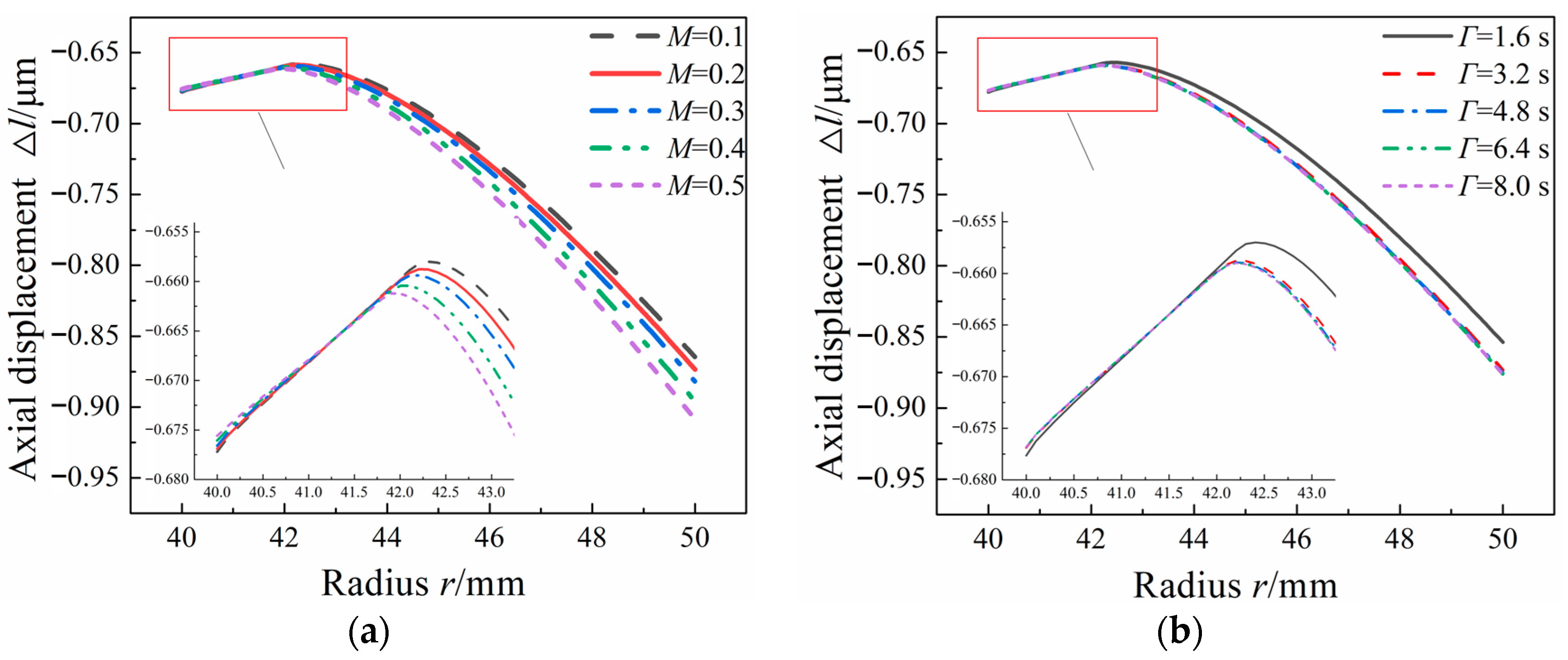
3.2.2. Alternating Rotational Speed
The thermal–mechanical coupling deformation trend of the seal ring under alternating rotational speed is close to that under alternating medium pressure. The contact also occurs at the inner diameter of the seal face and a tapered gap appears at the outer diameter of the seal face. The coupling deformation of the end face of the rotating ring is also larger than that of the stationary ring.
Figure 7 describes the axial displacement of the end face of the rotating ring along the radial direction under alternating rotational speeds with different amplitudes and periods. The coupling deformation trends of the end face of the rotating ring are all in a convex shape like that of the alternating medium pressure. With the increase in the amplitude of the alternating rotational speed, there is little change in coupling deformation at the inner diameter, but the axial displacement at the outer diameter increases gradually as shown in
Figure 7a. The main reason is that the friction heat of the seal face increases with the increase in the amplitude of the alternating rotational speed, and the temperature difference between the inner and outer diameters of the seal face increases gradually. When the amplitude
M is 0.1, the maximum axial displacement of the end face of the rotating ring |Δ
l| is about 0.865 μm. If
M is 0.5, the corresponding maximum axial displacement |Δ
l| is about 0.91 μm. As the amplitude increases, the taper angle on the outer diameter of the end face is also increased due to the increased temperature difference between the inner and outer diameters of the seal face. Compared with the results of the alternating medium pressure, the maximum coupling deformation of the end face of the rotating ring under alternating rotational speed is larger based on the same amplitude. The effect of alternating rotational speed on the coupling deformation of the seal face is more significant than that of alternating medium pressure.
In
Figure 7b, although the coupling deformation trend of the end face for different periods is in a similar convex shape, there is no obvious difference in coupling deformation of the end face as the period of the alternating rotational speed increases, especially in coupling deformation at the inner diameter of the end face. Compared with the results of alternating medium pressure with different periods, the axial displacement at the outer diameter of the end face is slightly different. When the period
Γ is 1.6 s, the maximum axial displacement of the end face |Δ
l| is about 0.85 μm. If the
Γ is 3.2 s, the maximum axial displacement |Δ
l| increases slightly by about 0.87 μm. If the alternating period
Γ continues to increase, there is no obvious difference in the maximum axial displacement of the end face due to the temperature distribution and contact state of the seal face reaching a steady state.
According to the above-mentioned results, it can be concluded that the influence of the alternating amplitude on the coupling deformation of the seal face is more significant than that of the alternating period.
When the working condition fluctuates alternately, the coupling deformation of the end face is larger than that in the stable working condition. The end face tends to be squeezed at the inner diameter side, and there is a tapered gap at the outer diameter of the seal face. Under alternating working conditions, the mechanical seal is in a state of high-frequency vibration, and the seal ring has a weak ability to resist and suppress alternating disturbance, which is prone to instability, especially for the instantaneous variation in rotational speed.
4. Discussion
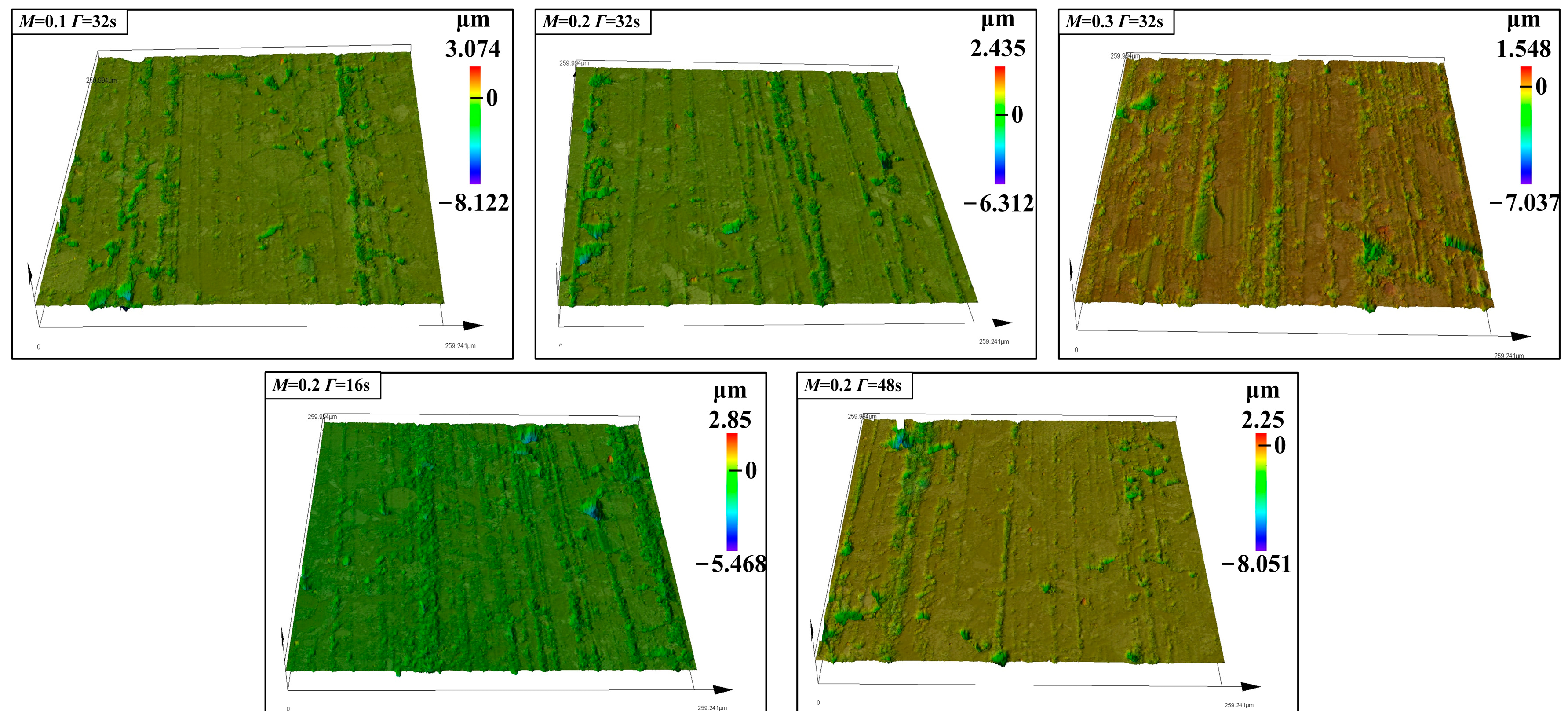
During the actual operation of the mechanical seal, wear inevitably occurs on the seal face, which may cause very adverse interference with the normal operation of the equipment. To further reveal the influence of the alternating working conditions on the performance of the mechanical face seal, the pseudo-real test study on the surface morphology and wear characteristics of the seal face is performed based on different alternating working conditions. Because SSiC has higher hardness and is more wear-resistant than M106K, the surface morphology of the end face of the rotating ring (M106K) is focused on in the paper.
When the medium pressure fluctuates periodically, it is easy to cause wear near the inner diameter of the end face of the rotating ring. The wear degree of the seal face under alternating medium pressure is increased compared with the results under stable conditions.
To further analyze the characteristics of the surface morphology of the rotating ring under alternating working conditions, the morphology of the end face of the rotating ring near the inner diameter is magnified 50 times under a three-dimensional (3-D) laser microscope.
Figure 8 presents the surface morphology of the end face of the rotating ring under alternating medium pressure with different amplitudes and periods. There are furrows with different depths appearing on the end face. The number of pits and furrows on the end face increases slightly with the increase in amplitude, and the width of the furrows also increases. This means that the wear of the end face of the rotating ring increases with the increase in the amplitude of the alternating medium pressure.
When the alternating amplitude is the same and the alternating period is varied, there is a small difference in the wear degree of the end face of the rotating ring. The alternating period has little influence on the wear of the end face of the rotating ring compared with the results based on different amplitudes.
From the test results, it can be concluded that the wear degree of the surface morphology at the inner diameter of the end face of the rotating ring is greater than that at the outer diameter of the end face. This indicates that the temperature at the inner diameter of the end face is higher and that this position is more prone to wear.
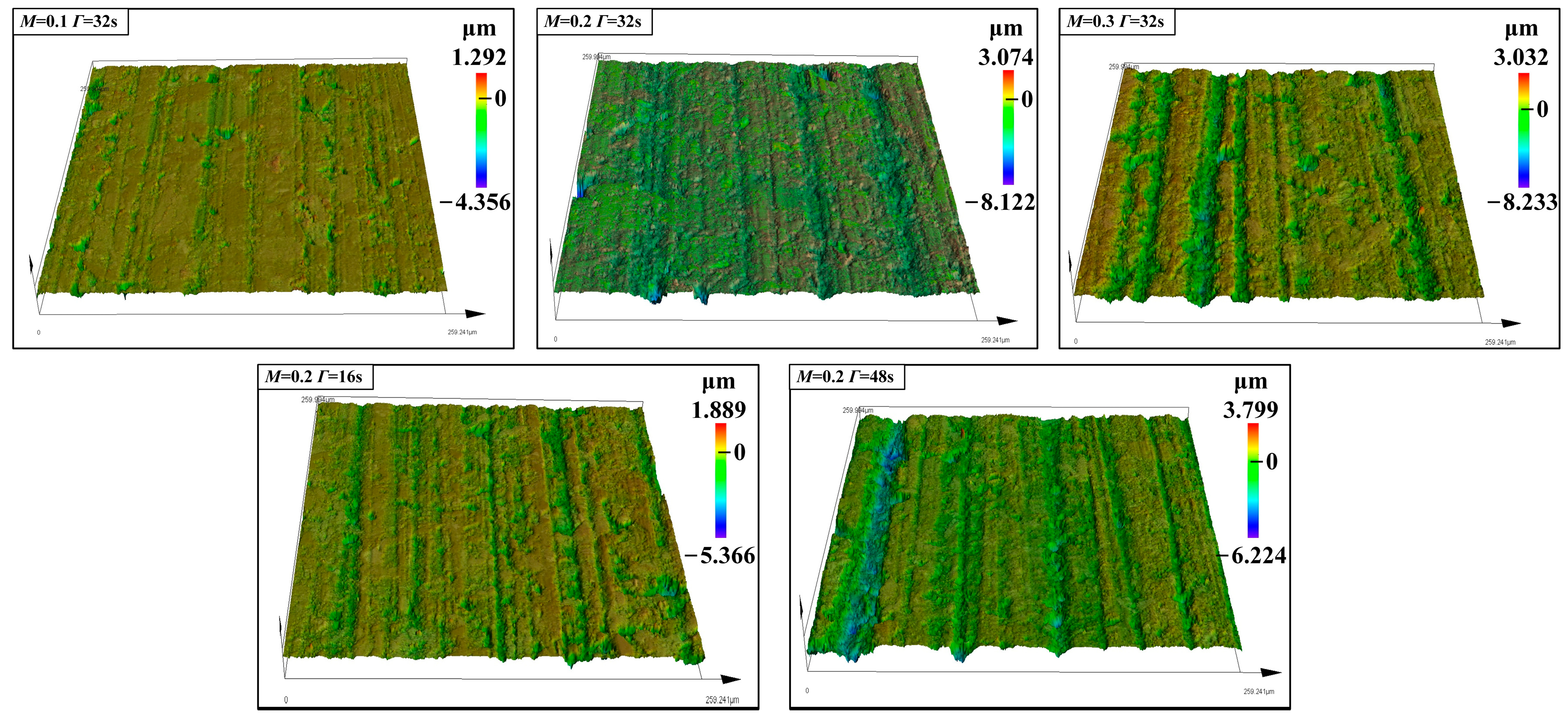
The surface morphology of the end face of the rotating ring under alternating rotational speed with different amplitudes and periods is described in
Figure 9. The influence of friction heat is particularly significant and the wear of the end face of the rotating ring is the most serious under the condition of the alternating rotational speed. This may be because the contact state of the friction pair changes continuously under the instantaneous alternating conditions, and the impregnated graphite part is carbonized at high temperature to form free abrasive particles and gather on the seal face, causing abrasive wear. When the alternating working conditions are intensified, a large area of material shedding occurs on the end face, and the number and width of furrows increase significantly. With the increase in the amplitude of the alternating rotational speed, the wear at the inner diameter of the end face is more serious than that at the outer diameter of the end face. In addition, compared with the results in
Figure 8, it can be found that the impact of alternating rotational speed on the wear of the end face is greater than that of alternating medium pressure.
When the period is increased, the width of the furrows also increases, although the increase is relatively small. Compared with the results of alternating rotational speed with different amplitudes, the alternating period has a limited influence on the wear of the end face of the rotating ring. In addition, although the wear effect of alternating rotational speed with different periods is slightly more significant than that of the alternating medium pressure with different periods as shown in
Figure 8, the overall effect of the alternating period is small relative to the alternating amplitude.
According to the test results described above, combined with the coupling deformation of the end face, the wear of the end face of the rotating ring is consistent with the coupling deformation trend of the end face of the rotating ring in the simulation. The larger the amplitude of the alternating load, the greater the deformation and wear of the end face of the rotating ring, and the effect of alternating rotational speed is more significant. However, the period of the alternating load has little effect on the deformation and wear of the end face of the rotating ring.
In addition, from the surface morphology of the rotating ring under alternating working conditions, it can be found that the wear of the end face of the rotating ring is more serious than under stable working conditions. This may be attributed to the alternating working condition causing the vibration of the shaft and chamber to a certain extent, resulting in secondary wear of the seal face.
Therefore, close attention should be paid to the adverse effects of complex and harsh working conditions on the mechanical seals, especially under the working conditions of alternating rotational speed. The occurrence of the resonance and vibration of the shaft and chamber should be avoided, and the deformation of the seal face should be minimized as much as possible through reasonable structural design and optimization, and its wear resistance should be enhanced by considering the advanced processing technologies for improving the actual operational stability and reliability of the mechanical seal.
In addition, the improved numerical model needs to be considered for more accurate calculation results. In the present numerical simulation, the sealing gap is assumed to be constant and convergent to simplify the calculation for deformation estimation. Based on the simulation results, to obtain more accurate and efficient calculation results, the two-way thermal–fluid–structural fully coupled iteration will be considered in the subsequent model improvement and optimization to enhance the precision and accuracy of the numerical simulation. In addition, the thermal boundary conditions directly affect the accuracy of the calculation of the temperature distribution of the seal ring. The empirical formula is used to calculate the convection heat transfer coefficients of the seal rings in the present research. There is a certain deviation from the convection heat transfer coefficient during actual operation, so the more accurate convective heat transfer coefficients through the experiments will be considered in the numerical model in future research.

