Abstract
Strengthening mechanisms were examined in a Fe-0.43C-1.60Si-0.01Mn-1.1Cr-0.95Mo-0.08V-0.05Nb steel exhibiting a yield strength (YS) of 1310 MPa after tempering and 1550 MPa after tempforming. The dislocation strengthening gave a major contribution to the overall YS of the steel in the tempered condition, whereas dispersion strengthening was a major contributor to the YS of the steel in the tempformed condition. High values of dislocation strengthening after tempering were attributed to dislocations composing the lath boundaries. A high density of free dislocations provided nearly the same dislocation strengthening after tempforming. Warm rolling after tempering led to alignment of intercrystallite boundaries along the rolling direction that decreased the interparticle spacing between M23C6 carbides located at these boundaries and thus increased the magnitude of dispersion strengthening. The boundary strengthening contributed to overall YS significantly due to small lath thickness after tempering and nanoscale spacing between lamellar boundaries after tempforming.
1. Introduction
Low-alloy ultra-high-strength (UHS) steels with yield strengths (YS) above 1400 MPa are used as structural materials for critical applications, especially in the aerospace industry, due to sufficient ductility and good toughness [1]. Heat treatment of UHS steels includes full austenitizing followed by water quenching and final low-temperature tempering. This treatment results in the formation of a low-temperature-tempered martensitic microstructure that provides a high strength but relatively low Charpy impact toughness [1]. A thermomechanical processing known as tempforming was developed by Japanese scientists to enhance the impact toughness [2,3,4]. This processing consists of austenitizing, water quenching, and high-temperature tempering at T ≥ 500 °C, followed by large-strain rolling at the same temperature. Tempforming increases the impact toughness by a factor of 10 along with a 30 pct increase in YS owing to the formation of a lamellar-type microstructure with the transverse crystallite dimension of ~100 nm [2,3,4,5,6]. Numerous works have dealt with the examination of fracture mechanisms in tempformed steels [2,3,4,7]. However, the strengthening mechanisms responsible for the YS increment after tempforming have not been studied in detail. D. Zhang et al. [8] suggested that grain boundary strengthening gives the largest contribution to the overall YS of a warm-rolled pearlitic steel plate. X. Zhang et al. [9] reported that the boundary strengthening attributed to small spacing between cementite lamellae and the dislocation strengthening associated with high dislocation density evolved during cold drawing were the major contributors to the strength of an eutectoid composition steel. In contrast, A. Dolzhenko et al. [5] considered the dispersion strengthening and the dislocation strengthening to be the major contributors to the strength of a Fe-0.08C-1.55Mn-1.16Cr-0.42Mo-0.17Si-0.08V-0.03Nb steel subjected to tempforming.
The aim of the present study is to evaluate and compare the strengthening mechanisms in a medium-carbon UHS steel after tempering and tempforming. Specific attention is paid to the effect of rolling on the contribution of different strengthening mechanisms to overall YS.
2. Materials and Methods
A medium-carbon steel with the chemical composition (in wt.%) of Fe-0.43C-1.60Si-0.01Mn-1.1Cr-0.95Mo-0.08V-0.05Nb-0.04Ti-0.003B-0.007S-0.004P was produced via air induction melting followed by electro-slag remelting. The ingots were subjected to hot forging at a temperature of 1150 °C followed by air cooling. Then, the billets were machined from the ingots and austenitized at a temperature of 900 °C for 40 min followed by water quenching. A part of the billets was tempered for 1 h at temperatures of 600 °C and 650 °C. These steel samples are denoted as QT600 and QT650, respectively. The other part was subjected to the tempforming process, which consisted of tempering followed by plate-rolling at the same temperature to a total strain of 1.4. Billets with dimensions of 45 mm × 32 mm × 153 mm (thickness × width × length) were used for tempforming. Reduction per one pass was about 8 pct and total number of passes was 17. Tempforming was conducted at 600 °C and 650 °C. These steel conditions are denoted here as TF600 and TF650, respectively.
The structural characterization of the steel samples was carried out using a JEM-2100 transmission electron microscope (TEM) (JEOL Ltd., Tokyo, Japan) and a Quanta 600 FEG scanning electron microscope (FEI Corporation, Hillsboro, OR, USA) incorporating an orientation imaging microscopy (OIM) system. The OIM mapping based on automatic analysis of electron back-scattering diffraction (EBSD) patterns was performed with a relatively small scan-step size of 30 nm. The density of lattice dislocation on TEM micrographs was estimated by counting the individual dislocations within martensite laths per unit area. The density of dislocations with like sign and dislocations in lath/subgrain boundaries (ρ*) was estimated using Kernel Average Misorientation (θKAM) using TSL OIM Analysis 6 software, setting the maximal misorientation of 15°, as
where b and h are the Burgers vector and the OIM step size, respectively [10]. The Tailor factors were calculated from the OIM data along the rolling direction using TSL OIM Analysis 6 software. The high-angle (HAB) and low-angle boundaries (LAB) were defined when the adjacent pixels in the OIM maps exhibited a misorientation of θ ≥ 15° and 2 < θ < 15°, and these boundaries are depicted using black and white lines, respectively, in the OIM micrographs.
The tensile tests of flat specimens with a cross-sectional area of 7 × 3 mm2 and a 35 mm gauge length were carried out at room temperature using an Instron 5882 testing machine (Illinois ToolWorks Inc., Norwood, MA, USA).
The equilibrium mass fractions of the alloying elements in solid solution and the volume fractions of precipitated phases were calculated using Thermo-Calc software (Ver. 5, Thermo-Calc Software, Stockholm, Sweden) using the TCFE7 database.
3. Results
3.1. Microstructure
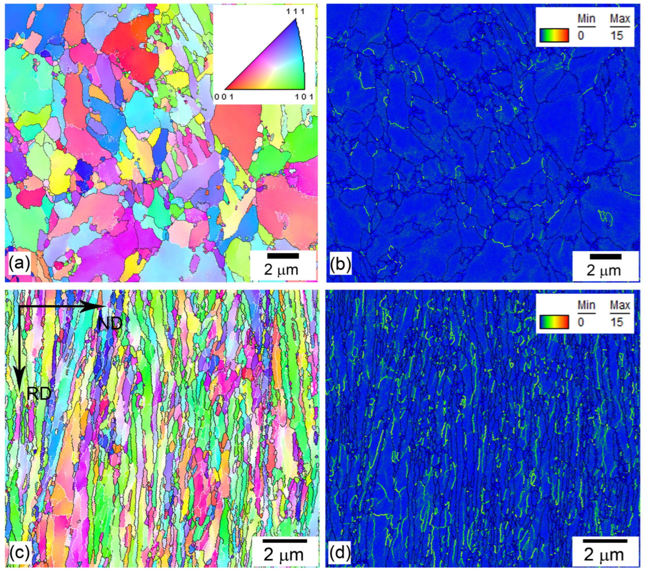
Some of the microstructural features such as the texture, the distance between HAB, the transverse lath/subgrain size after tempering and tempforming at 600 °C and 650 °C with a total strain of 1.4 were described in previous papers [6,11]. The main structural parameters of the steel in four different conditions are summarized in Table 1. Typical OIM maps and TEM images of the steel after tempering and tempforming at different temperatures are shown in Figure 1, Figure 2 and Figure 3. After tempering at 600 or 650 °C, the tempered martensite lath structure (TMLS) with an average distance between HAB of 1.1 μm evolved (Figure 1a and Figure 2a). The dislocations were mainly collected in dislocation sub-boundaries (Figure 1b and Figure 2b). The average KAM values were 0.46 and 0.56 after tempering at 600 and 650 °C, respectively. Tempforming led to the formation of a lamellar microstructure consisting of LABs and HABs aligned in the rolling direction (RD) (Figure 1c,d and Figure 2c,d). It is obvious (Table 1) that the prior austenite grains and packets tended to deform as a whole billet. As a result, the distances between HABs in normal direction (ND) decreased by factors of ~3 and ~5 during tempforming at 600 and 650 °C, respectively. Warm rolling after tempering induced dynamic recovery at 600 °C and continuous dynamic recrystallization (cDRX) at 650 °C. LABs also aligned with RD and lamellar microstructure consisted of longitudinal LABs and HABs (Figure 2a,b). The spacing between LABs decreased and the density of free dislocations within lamellae increased during warm rolling (Table 1, Figure 3f). As a result, the average KAM values increased to 0.92° and 0.85° after tempforming at 600 and 650 °C, respectively (Figure 1c and Figure 2c, Table 1).

Table 1.
Structural parameters of the medium-carbon UHS steel after tempering and tempforming.
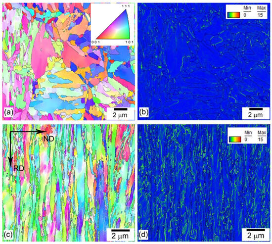
Figure 1.
Typical EBSD (a,c) and KAM (b,d) maps of medium-carbon low-alloy steel after tempering at 600 °C (a,b) and tempforming at 600 °C (c,d) with true strain of 1.4. Black and white lines in EBSD maps (a,c) indicate HAB and LAB, respectively.
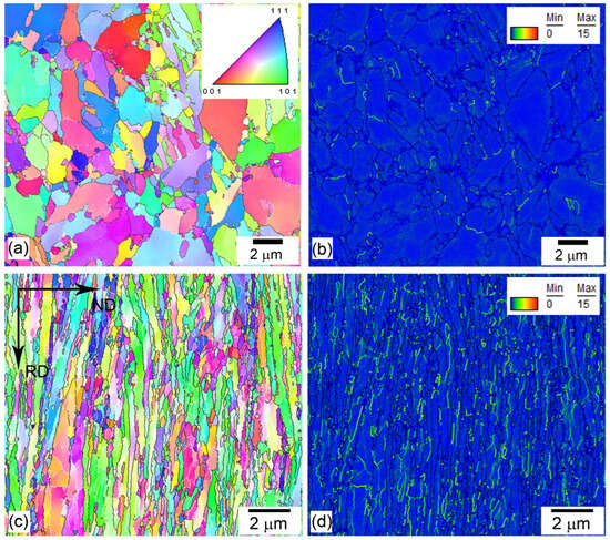
Figure 2.
Typical EBSD (a,c) and KAM (b,d) maps of medium-carbon low-alloy steel after tempering at 650 °C (a,b) and tempforming at 650 °C (c,d) with true strain of 1.4. Black and white lines in EBSD maps (a,c) indicate HAB and LAB, respectively.
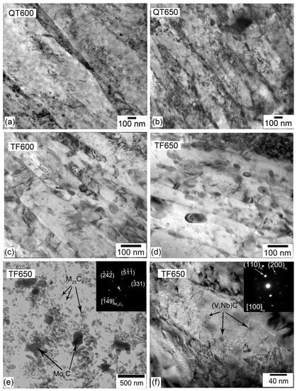
Figure 3.
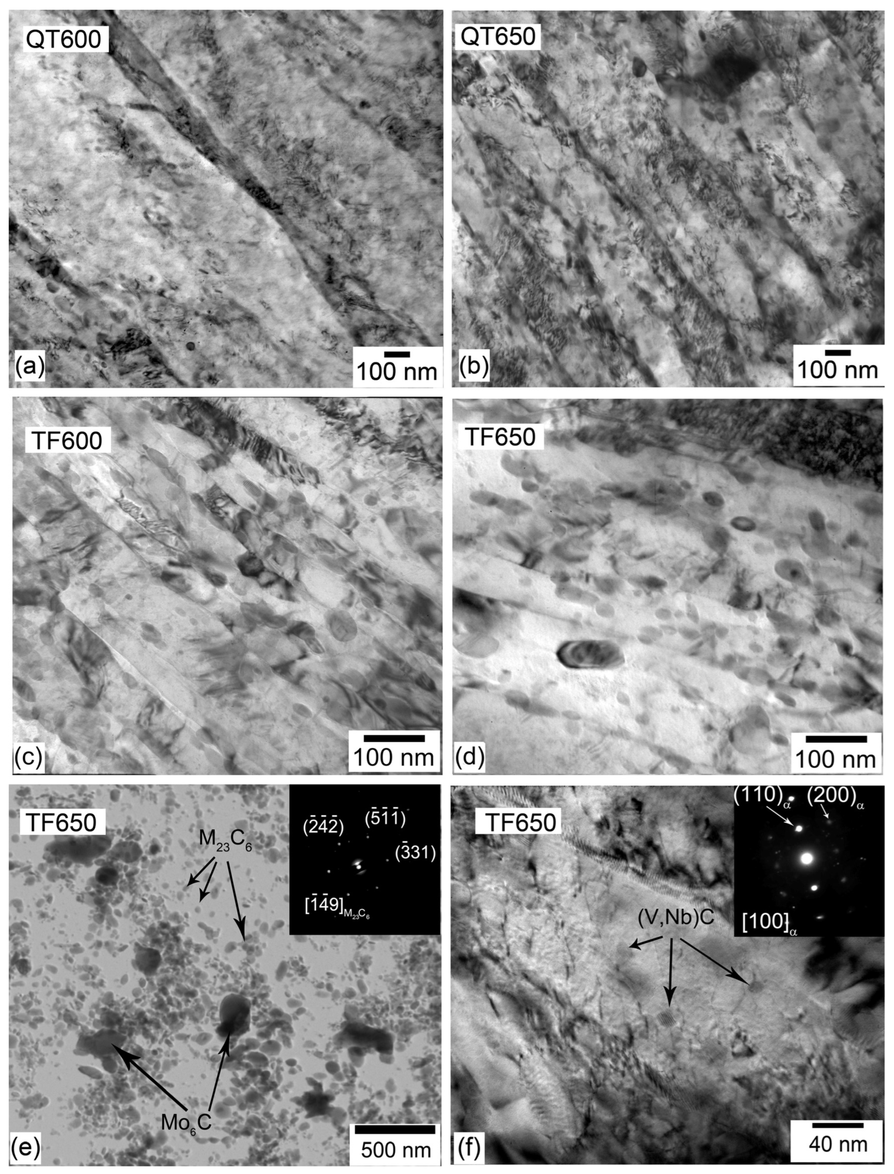
Typical TEM micrographs of medium-carbon low-alloy steel after tempering (QT) and tempforming (TF) at temperatures of 600 °C (a,c) and 650 °C (b,d–f): lath/subgrain structure (a–d); typical dispersion particles on carbon replica (e), dislocations and (V,Nb)C carbides within subgrains after warm rolling (f).
TMLS is characterized by high internal stresses as suggested by bend contrast at TEM images in Figure 3a,b. These stresses are exerted by lath boundaries, which are an irregular dislocation network [12]. An increase in tempering temperature from 600 to 650 °C decreases the density of free dislocations within laths and, therefore, elastic stress fields. The TEM images after warm rolling show a lack of the specific bend contrast (Figure 3c,d) that is indicative for the rearrangement of intrinsic boundary dislocations and transformation of lath boundaries to ordinary subgrain boundaries free of long-range internal stresses [13].
The tempered microstructures contained numerous precipitates (Figure 3a,b). M6C carbides were located on the boundaries of prior austenite grains and M23C6 carbides on LABs and HABs [11]. It is worth noting that only carbides located on block and lath boundaries may contribute to dispersion strengthening. The volume fraction of relatively large M6C carbides is low and comprises 0.6% (Table 1, Figure 3e). Therefore, the contribution of M6C carbides to overall YS will be not considered in the present study. The carbides of (V,Nb)C with an average size of 46 nm were homogeneously distributed in subgrain interiors (Figure 3f). The volume fraction of (V,Nb)C carbides was comparable to M6C carbides, but the density of those particles is remarkably higher because of their smaller size. Therefore, the contribution of (V,Nb)C carbide particles to overall YS will be taken into consideration. The M23C6 carbides comprise chains along the low- and high-angle lamellar boundaries (Figure 3c–e). The interparticle spacing between M23C6 carbides and the transverse distance between LABs are nearly the same.
3.2. Tension Mechanical Properties
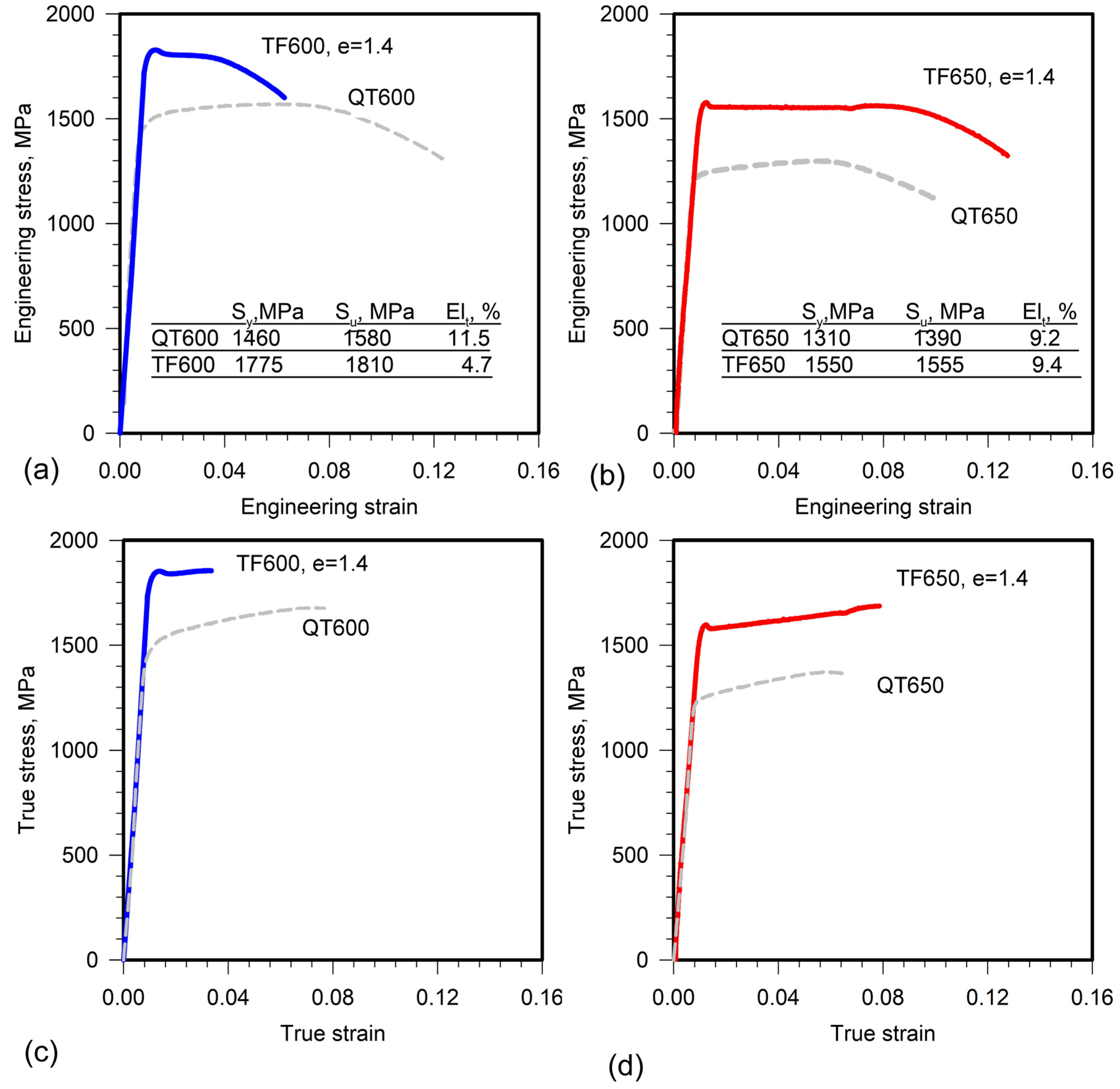
The engineering and true stress–strain curves after tempering and tempforming are shown in Figure 4. The medium-carbon steel was significantly strengthened by tempforming in comparison with tempering. YS increased by 315 MPa and 240 MPa after warm rolling at 600 °C and 650 °C, respectively (Figure 4a,b). An increase in temperature from 600 to 650 °C resulted in an 8% (150 MPa) and 12% (225 MPa) decrease in YS after tempering and tempforming, respectively (Figure 4a,b). Therefore, the temperature effect on the YS of tempformed steel is stronger than that on the YS of tempered steel.
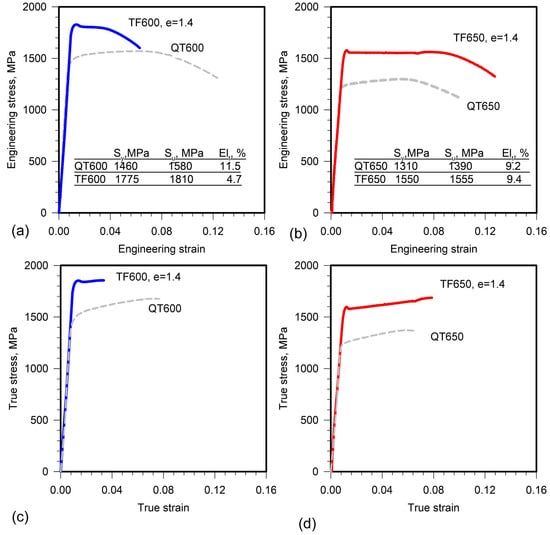
Figure 4.
Engineering (a,b) and true (c,d) stress–strain curves of medium-carbon low-alloy steel. The bold blue and red lines represent tensile properties after tempforming (TF) at (a,c) 600 °C and (b,d) 650 °C, respectively. The dashed lines show curves for the steel samples quenched and tempered at (a,c) 600 °C (QT600) and (b,d) 650 °C (QT650). Table inserts summarize the values of yield strength, Sy, ultimate tensile strength, Su, and total elongation, Elt, for reference.
Warm rolling after tempering leads to transition from continuous to discontinuous yielding. The tempformed steel exhibits Piobert–Luders deformation behavior [14,15] with upper yield strength, a characteristic drop in the true stress–strain curves, and a short yielding plateau with distinct low yield strength [14] followed by apparent steady state until rupture (Figure 4c,d). It is worth noting that tempered steel exhibits a work-hardening stage after continuous yielding. The low yield strength [14] will be considered as YS to analyze the strengthening mechanisms for the tempformed steel samples.
4. Discussion
Different strengthening mechanisms could be operative in low-alloy steels [5,8,9,16,17]. It is well-known that all strengthening mechanisms give additive contributions, and overall YS can be expressed as
where is the Peierls–Nabarro or friction stress of high-purity ferrite, is the solid solution strengthening by substitutional and interstitial elements in ferrite, is the dispersion strengthening attributed to M23C6 carbides and (V,Nb)C carbides in the present work, , is the dislocation strengthening, and is the grain size strengthening. ~45 MPa is usually adopted for calculation of the YS in low-alloy steels [5,16].
Pickering’s empirical equation in the form of
is widely used for the calculation of solid solution strengthening originating from substitutional and interstitial solutes [16,17]. The concentrations in Equation (3) are expressed in wt.%. The ferrite matrix is significantly depleted by carbon, chromium, and molybdenum due to precipitation of numerous carbides during tempering. Data reported by X. Zhang et al. [9] showed that dissolution of carbides due to plastic deformation is insignificant and the contribution of solid solution strengthening to overall YS is not important for strains up to about 2.67. Therefore, experimental concentrations of solute elements in the ferritic matrix could be taken from the Thermo-Calc equilibrium calculation (Table 2). The concentrations of other elements are negligible and were discarded from calculation of the solid solution strengthening. The sum of the friction stress and the solid solution strengthening, , was calculated to be 61 and 74 MPa for the present steel at 600 and 650 °C, respectively. These values support the low effect of solid solution strengthening on overall YS reported by X. Zhang et al. [9].
σSS = 32 Mn − 31 Cr + 11 Mo + 5544 Css,
Table 2.
Equilibrium chemical composition of ferrite matrix of medium-carbon steel at 600 and 650 °C calculated with Thermo-Calc software.
Dispersion strengthening is generally attributed to the Orowan mechanism and can be evaluated with the following equation [5,18]:
where λ is the interparticle spacing, M is the Taylor factor taken from Table 1, G = 81 GPa is the shear modulus, b = 0.248 nm is the Burgers vector, d* depends on the ratio between dP and λ and can be calculated as d* = (dP−1 + λ−1)−1, and r0 is the dislocation core dimension of approximately 2b. The interaction between the (V,Nb)C carbides precipitated in the ferritic matrix and the gliding dislocations contributes to the overall dispersion strengthening due to Orowan bowing in accordance with Equation (4). The interparticle spacing is calculated as λ = 0.2dp (π/Fv)0.5 for these dispersoids with an average size of dP and the volume fraction, FV, taken from Table 1. The interparticle spacing for M23C6 carbides is taken as the transverse dimensions of laths or lamellae. The M23C6 carbides located at boundaries of blocks and laths may contribute to the overall dispersion strengthening in TMLS if the dislocation glide occurs along the laths on two possible <111> slip directions leading to attractive interaction between a gliding dislocation and boundary particles [19,20]. This dislocation glide occurs parallel to the lath interfaces along laths in TMLS and is known as in-lath slip [20]. The dislocation glide with two other <111> slip directions, known as out-of-lath slip [20], could not interact with the boundary particles. Large straining during tempforming provides significant re-orientation of lattice. In the lamellar structure the in-lath slip can occur in {110} <111> grains via the dislocation glide along two possible <111> slip directions in the lamellae on a {110} plane lying parallel to longitudinal lamellae boundaries and RD [4]. Therefore, boundary M23C6 carbides contribute to YS after tempering and tempforming. Since the interaction mechanisms of gliding dislocations with (V,Nb)C carbides and boundary M23C6 carbides are different, the Pythagorean addition rule, i.e., ΔσP = (σOr12 + σOr22)0.5, [16,21] is used to calculate the overall dispersion strengthening (Table 3).
σp = 0.2 MGbλ−1(ln(d*/r0) + 0.7),
Table 3.
Contribution of different strengthening mechanisms to overall YS after tempering (QT) and tempforming (TF) at different temperatures.
The grain size strengthening can be expressed by the second term of the well-known Hall–Petch relationship [5,8,9,16,17,22,23]
where d is the effective grain size and ky is the Hall–Petch slope. The effective grain size is taken as a double lamellar/lath thickness taking into account the volume available for the formation of pile-ups in the lamellae [9]. The ky value of 0.31 MPa·m−2 describes with a high accuracy the grain boundary strengthening in medium-carbon steels [24]. The resulted values of the grain size strengthening are presented in Table 3.
σHP = kyd−0.5,
The dislocation strengthening from the interior dislocations is described by a Taylor-type relationship [5,8,9,16,17]:
where ρ is the density of free interior dislocations taken from Table 1, α is a constant (0.24 for low-alloy steels [9,16]). The dislocation strengthening, σd, attributed to free lattice dislocations located within the laths or lamellae, is presented in Table 3. Lath boundaries are irregular dislocation arrays may also contribute to the dislocation strengthening [12,25,26,27]. Intrinsic dislocations composing lath boundaries and free dislocations contribute to the dislocation strengthening due to long-range elastic stress fields [17]. These fields correlate with the ρKAM value. The dislocation strengthening, , attributed to dislocations with like sign and calculated with Equation (6) using the ρKAM value from Table 1 is presented in Table 3.
σd = αMGbρ0.5,
This dislocation strengthening () is remarkably higher than σd and, therefore, the contribution of intrinsic lath boundary dislocations to overall dislocation strengthening is higher than that of free interior dislocations in the tempered condition. The resulting values of YS, , for QT600 and QT650 treatments are calculated as follows:
and presented in Table 3.
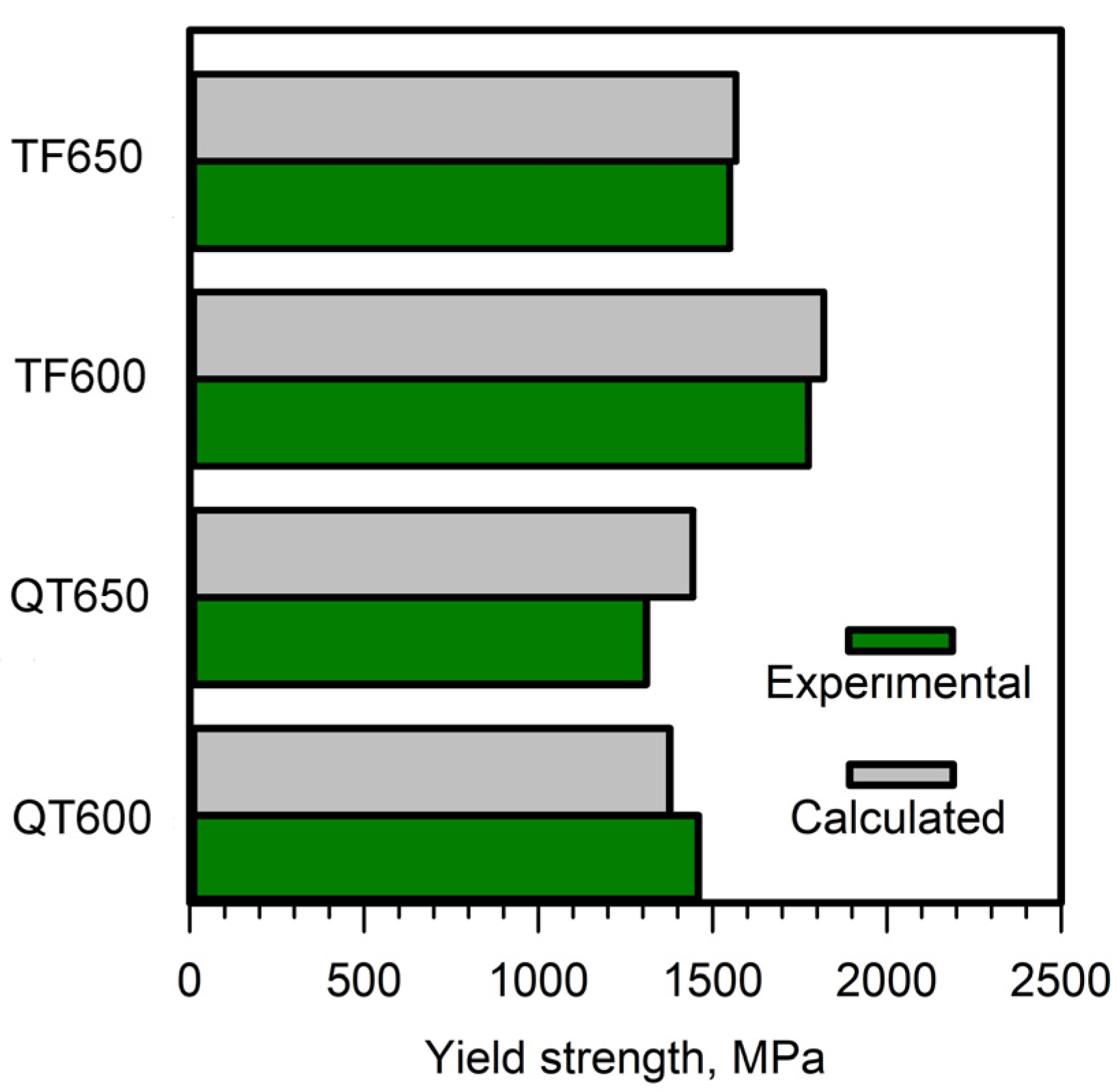
A comparison between experimentally measured YS from Figure 4 and calculated YS from Table 3 is shown in Figure 5. It can be seen that the experimental YSs match theoretical values for the tempered steel with high accuracy, suggesting the contribution of intrinsic lath boundary dislocations to the dislocation strengthening. Theoretical values of the steel after tempforming and experimental YSs are essentially the same if the dislocation strengthening calculated by Equation (6) using density of free dislocation, ρ, is taken into account. The use of the ρKAM values for the steel in tempformed condition leads to significant overestimation of theoretical YS. Therefore, intrinsic dislocations of LABs in lamellar structure do not contribute to the dislocation strengthening due to lacking the long-range elastic stress fields. The lacking of long range elastic stress fields originating from lamellar boundaries has been found in TEM studies (Figure 3c,d). High ρKAM values (Table 1) may be calculated due to accumulative misorientation of LABs with nanoscale spacing in the lamellar structure. Subbondaries in lamellar structures do not contribute to the dislocation strengthening.

Figure 5.
Comparison between experimentally measured yield stresses and those predicted by different strengthening mechanisms in medium-carbon low-alloy steel.
Inspection of Table 3 shows that the dislocation strengthening is the major contributor to YS of the tempered steel. The dispersion strengthening and the grain size strengthening are also important for the YS of this material, while the role of the solid solution strengthening is insignificant due to almost full carbon depletion from ferrite. It is worth noting that the contributions of boundary M23C6 carbides and (V,Nb)C carbides to overall dispersion strengthening are nearly the same, and, therefore, small additions of Nb are effective in increasing the YS of low-alloy steel [11]. The boundary M23C6 carbides also contribute to the strength due to the formation of chains at lath and block boundaries. It seems that the small lath thickness at relatively high tempering temperatures is associated with high Zener drag pressure exerted by these chains [28]. The dispersed M23C6 carbides and (V,Nb)C carbides prevent recovery in lath boundaries and relieving internal stress up to high tempering temperatures that provides high values of the dislocation strengthening in this material condition. Thus, thin laths and lath boundaries exerting long-range elastic stress fields are key factors for attaining high YS in tempered low-alloy steels.
Warm rolling after tempering increases YS due the replacement of TMLS by lamellar structure. The alignment of boundary M23C6 carbide chains along RD significantly increases the dispersion strengthening due to decreased interparticle spacing. As a result, the dispersion strengthening becomes the major contributor to overall YS in tempformed steel with a high volume fraction of boundary M23C6 carbides. It seems that tempforming provides about 50% increment in YS of medium-carbon low-alloy steels [2,3,4,6] in comparison with low-carbon steels [5,7] due to the frequent M23C6 carbide chains on the lamellar boundaries after tempforming. These chains contribute to YS through dispersion strengthening. In addition, the dispersion of boundary M23C6 carbides and matrix (V,Nb)C carbides provides very small interboundary spacing in the lamellar structure that gives the large contribution of grain size strengthening. This is an indirect effect of M23C6 carbides and (V,Nb)C carbides on YS of the medium-carbon low-alloy steel. Warm rolling relives internal stress exerted by lath boundaries owing to dynamic recovery. Concurrently, warm rolling increases the density of free interior dislocations. As a result, the values of dislocation strengthening remain high. Thus, the dispersion strengthening, the grain size strengthening, and the dislocation strengthening are the major contributors to YS of the tempformed steel.
5. Conclusions
- Dislocation strengthening gives the largest contribution to the overall yield strength of ~1400 MPa in the medium-carbon low-alloy steel in tempered condition due to small lath thickness and internal stresses originating from lath boundaries. Thin laths also provide relatively high values of grain size strengthening and dispersion strengthening. Low-angle boundaries in lamellar structure give no contribution to the dislocation strengthening of the present steel subjected to tempforming. High values of the grain size strengthening are attributed to small spacing between lamellar boundaries in the steel after tempforming.
- Dispersion strengthening is the major contributor to the overall yield strength ranging from 1550 to 1775 MPa in tempformed steel due to the formation of frequent M23C6 carbide chains on lamellar boundaries and small interboundary spacing of lamellar structure. The latter also provides high values of grain size strengthening. The high density of free dislocations induced by warm rolling is the third factor providing high yield strength.
- The dispersion of boundary M23C6 carbides and matrix (V,Nb)C carbides plays a key role in the yield strength of the steel in tempered and tempformed conditions. The direct effect of dispersoids on the yield strength is associated with dispersion strengthening, whereas indirect enhancement of the strength is attributed to the influence of M23C6 carbides and (V,Nb)C carbides on the characteristics of the tempered martensite lath structure and the lamellar structure that provides high values of the grain size strengthening and the dislocation strengthening.
Author Contributions
Conceptualization, V.D. and R.K.; methodology, V.D. and D.Y.; validation, D.Y.; formal analysis, V.D.; investigation, D.Y., V.D. and R.K.; resources, R.K.; data curation, D.Y. and V.D.; writing—original draft preparation, V.D. and R.K.; writing—review and editing, D.Y.; visualization, D.Y. and V.D.; supervision, R.K.; project administration, R.K.; funding acquisition, R.K. All authors have read and agreed to the published version of the manuscript.
Funding
This research was funded by the Ministry of Science and Higher Education of the Russian Federation, grant number 075-15-2021-572.
Institutional Review Board Statement
Not applicable.
Informed Consent Statement
Not applicable.
Data Availability Statement
Not applicable.
Acknowledgments
The studies were carried out on the equipment of the Joint Scientific Center for Technologies and Materials of Belgorod State National Research University, which was supported by the Ministry of Science and Higher Education of the Russian Federation under contract No. 075-15-2021-690 (unique identifier RF—2296.61321X0030).
Conflicts of Interest
The authors declare no conflict of interest.
References
- Krauss, G. Steels: Processing Structure, and Performance, 2nd ed.; ASM International: Materials Park, OH, USA, 2005. [Google Scholar]
- Kimura, Y.; Inoue, T.; Yin, F.; Tsuzaki, K. Inverse Temperature Dependence of Toughness in an Ultrafine Grain-Structure Steel. Science 2008, 320, 1057–1060. [Google Scholar] [CrossRef] [PubMed]
- Kimura, Y.; Inoue, T.; Tsuzaki, K. Tempforming in Medium-Carbon Low-Alloy Steel. J. Alloys Compd. 2013, 577, S538. [Google Scholar] [CrossRef]
- Kimura, Y.; Inoue, T. Mechanical Property of Ultrafine Elongated Grain Structure Steel Processed by Warm Tempforming and Its Application to Ultrahigh-Strength Bolt. ISIJ Int. 2020, 60, 1108–1126. [Google Scholar] [CrossRef]
- Dolzhenko, A.; Pydrin, A.; Gaidar, S.; Kaibyshev, R.; Belyakov, A. Microstructure and Strengthening Mechanisms in an Hsla Steel Subjected to Tempforming. Metals 2022, 12, 48. [Google Scholar] [CrossRef]
- Yuzbekova, D.; Dudko, V.; Pydrin, A.; Gaidar, S.; Mironov, S.; Kaibyshev, R. Effect of Tempforming on Strength and Toughness of Medium-Carbon Law-Alloy Steel. Materials 2023, 16, 1202. [Google Scholar] [CrossRef]
- Dolzhenko, A.; Kaibyshev, R.; Belyakov, A. Tempforming as an Advanced Processing Method for Carbon Steels. Metals 2020, 10, 1566. [Google Scholar] [CrossRef]
- Zhang, D.; Zhang, M.; Cao, K.; Ning, J.; Feng, Y. Effect of Annealing Time on Microstructure Stability and Mechanical Behavior of Ferrite-Cementite Steel with Multiscale Lamellar Structure. Metall. Mater. Trans. B Process Metall. Mater. Process. Sci. 2021, 52, 1023–1033. [Google Scholar] [CrossRef]
- Zhang, X.; Godfrey, A.; Huang, X.; Hansen, N.; Liu, Q. Microstructure and Strengthening Mechanisms in Cold-Drawn Pearlitic Steel Wire. Acta Mater. 2011, 59, 3422–3430. [Google Scholar] [CrossRef]
- Calcagnotto, M.; Ponge, D.; Demir, E.; Raabe, D. Orientation Gradients and Geometrically Necessary Dislocations in Ultrafine Grained Dual-Phase Steels Studied by 2D and 3D EBSD. Mater. Sci. Eng. A 2010, 527, 2738–2746. [Google Scholar] [CrossRef]
- Dudko, V.; Yuzbekova, D.; Gaidar, S.; Vetrova, S.; Kaibyshev, R. Tempering Behaviour of Novel Low-Alloy High-Strength Steel. Metals 2022, 12, 2177. [Google Scholar] [CrossRef]
- Dudko, V.; Belyakov, A.; Kaibyshev, R. Evolution of Lath Substructure and Internal Stresses in a 9% Cr Steel during Creep. ISIJ Int. 2016, 57, 3–6. [Google Scholar] [CrossRef]
- Humphreys, F.J.; Hatherly, M. Recrystallization and Related Annealing Phenomena; Elsevier: Oxford, UK, 2005. [Google Scholar]
- Schwab, R.; Ruff, V. On the Nature of the Yield Point Phenomenon. Acta Mater. 2013, 61, 1798–1808. [Google Scholar] [CrossRef]
- Antolovich, S.D.; Armstrong, R.W. Plastic Strain Localization in Metals: Origins and Consequences. Prog. Mater. Sci. 2014, 59, 1–160. [Google Scholar] [CrossRef]
- Xiong, Z.; Timokhina, I.; Pereloma, E. Clustering, Nano-Scale Precipitation and Strengthening of Steels. Prog. Mater. Sci. 2021, 118, 100764. [Google Scholar] [CrossRef]
- Gutiérrez, I.; Altuna, M.A. Work-Hardening of Ferrite and Microstructure-Based Modelling of Its Mechanical Behaviour under Tension. Acta Mater. 2008, 56, 4682–4690. [Google Scholar] [CrossRef]
- Queyreau, S.; Monnet, G.; Devincre, B. Orowan Strengthening and Forest Hardening Superposition Examined by Dislocation Dynamics Simulations. Acta Mater. 2010, 58, 5586–5595. [Google Scholar] [CrossRef]
- Na, H.; Nambu, S.; Ojima, M.; Inoue, J.; Koseki, T. Crystallographic and Microstructural Studies of Lath Martensitic Steel during Tensile Deformation. Met. Mater. Trans. A Phys. Met. Mater. Sci. 2014, 45, 5029–5043. [Google Scholar] [CrossRef]
- Inoue, J.; Sadeghi, A.; Koseki, T. Slip Band Formation at Free Surface of Lath Martensite in Low Carbon Steel. Acta Mater. 2019, 165, 129–141. [Google Scholar] [CrossRef]
- Koppenaal, T.J.; Kuhlmann-Wilsdorf, D. The Effect of Prestressing on the Strength of Neutron-Irradiated Copper Single Crystals. Appl. Phys. Lett. 1964, 4, 59–61. [Google Scholar] [CrossRef]
- Hall, E.O. The Deformation and Ageing of Mild Steel III Discussion of Results. Proc. Phys. Society. Sect. B 1951, 64, 747. [Google Scholar] [CrossRef]
- Petch, N.J. The Cleavage Strength of Polycrystals. J. Iron Steel Inst. 1953, 174, 25–28. [Google Scholar]
- Takaki, S.; Akama, D.; Nakada, N.; Tsuchiyama, T. Effect of Grain Boundary Segregation of Interstitial Elements on Hallpetch Coefficient in Steels. Mater. Trans. 2014, 55, 28–34. [Google Scholar] [CrossRef]
- Naylor, J.P. The Influence of the Lath Morphology on the Yield Stress and Transition Temperature of Martensitic-Bainitic Steels. Metall. Trans. A 1979, 10, 861–873. [Google Scholar] [CrossRef]
- Harrell, T.J.; Topping, T.D.; Wen, H.; Hu, T.; Schoenung, J.M.; Lavernia, E.J. Microstructure and Strengthening Mechanisms in an Ultrafine Grained Al-Mg-Sc Alloy Produced by Powder Metallurgy. Met. Mater. Trans. A Phys. Met. Mater. Sci. 2014, 45, 6329–6343. [Google Scholar] [CrossRef]
- Argon, A.S. Strengthening Mechanisms in Crystal Plasticity; Oxford University Press: New York, NY, USA, 2008. [Google Scholar]
- Mishnev, R.; Dudova, N.; Kaibyshev, R. On the Origin of the Superior Long-Term Creep Resistance of a 10% Cr Steel. Mater. Sci. Eng. A 2018, 713, 161–173. [Google Scholar] [CrossRef]

Disclaimer/Publisher’s Note: The statements, opinions and data contained in all publications are solely those of the individual author(s) and contributor(s) and not of MDPI and/or the editor(s). MDPI and/or the editor(s) disclaim responsibility for any injury to people or property resulting from any ideas, methods, instructions or products referred to in the content. |
© 2023 by the authors. Licensee MDPI, Basel, Switzerland. This article is an open access article distributed under the terms and conditions of the Creative Commons Attribution (CC BY) license (https://creativecommons.org/licenses/by/4.0/).