Article

LoRaWAPS: A Wide-Area Positioning System Based on LoRa Mesh

1
State Key Laboratory of Industrial Control Technology, Zhejiang University, Hangzhou 310027, China
2
Department of Information Engineering, Yangzhou Polytechnic College, Yangzhou 225009, China
3
College of Information Science and Electronic Engineering, Zhejiang University, Hangzhou 310027, China
4
College of Control Science and Engineering, Zhejiang University, Hangzhou 310027, China
*
Author to whom correspondence should be addressed.
Appl. Sci. 2023, 13(17), 9501; https://doi.org/10.3390/app13179501
Submission received: 30 June 2023 / Revised: 8 August 2023 / Accepted: 17 August 2023 / Published: 22 August 2023

Abstract

:
The positioning task of the Internet of Things (IoT) for outdoor environments requires that the node devices meet the requirements of low power consumption, long endurance, and low cost and that the positioning system can achieve high-precision positioning and wide-area coverage. Considering that traditional IoT positioning technology cannot balance the cost, energy consumption, and positioning performance well, a Wide-Area Positioning System Based on Long Range Mesh (LoRaWAPS), which is a low-cost and low-power outdoor positioning system with multi-anchor wireless mesh networking and multi-dimensional data fusion, is designed in this paper. To meet the need for a positioning system, a low-power consumption and high-reliability LoRa Mesh protocol is proposed. Aiming at the problem that the accuracy of LoRa ranging is easily affected by the non-line-of-sight (NLOS) path propagation of signals, a distance estimation algorithm based on the fusion of time of flight (TOF) and received signal strength indicator (RSSI) multi-sampling data is proposed. Furthermore, a position estimation algorithm is designed to minimize the posteriori RSSI error for multi-anchor cooperative estimation scenarios. Furthermore, the prototype of LoRaWAPS is built and tested in the campus environment. The experimental results show that the proposed system can provide reliable location service with low power and low cost.

1. Introduction

With the rapid development of IoT, the demand for obtaining location information is constantly emerging in industries, transportation, agriculture, and other fields. Spatial positioning is a typical scenario and key feature of the Internet of Things in the mass application, and will become more important in the next generation of IoT network [1]. In recent years, a series of outdoor positioning applications have emerged, including tracking the location and movement of livestock in diet monitoring and meat tracing, positioning of key residential facilities and vehicles in smart cities, and so on.
The characteristics of the aforementioned outdoor wide-area location services are as follows: (1) low-cost IoT nodes (including user terminal equipment) are often dependent on their own power supply and are energy-sensitive [2]. (2) The outdoor environment is complicated, including non-line-of-sight (NLOS) [3], multipath [4], wide area [5], and multilayer effect [6], as well as interference from moving objects and human [7]. (3) The error of low-cost sensors is large and changes over time, and it is easy to be affected by environmental factors (such as temperature) [8].
Mainstream IoT positioning systems include Global Navigation Satellite Systems (GNSS), cellular mobile network positioning, and positioning systems based on Low-Power Wide-Area Networks (LPWAN), WiFi, Bluetooth, ZigBee, Near Field Communication (NFC), Radio Frequency Identification (RFID) and other wireless communication technologies. Among them, WiFi, Bluetooth, ZigBee, NFC, and RFID can only be used in indoor positioning scenarios due to their limited communication range. Standalone GNSS can provide positioning services worldwide; however, the performance of positioning will degrade due to interruptions, degradation, and multipath in urban environments. In addition, a GNSS module costs more than 10 USD with a power consumption of 120 mW. A 4G module is about 15 USD with an average power consumption larger than 300 mW [9]. With consideration of the cost and power consumption, GNSS and cellular positioning are usually not considered in wide-area IoT positioning [2,10]. LPWAN is capable of long-distance communication at low bit rates, which can simultaneously meet the requirements of signal coverage, cost, and battery life. Therefore, how to obtain accurate position estimation from radio signals transmitted by LPWAN equipment has become a hot topic in current research.
As a representative LPWAN technology, Long Range (LoRa) has strong anti-noise ability and long-distance communication ability. LoRa has telecommunication capabilities, and a small number of LoRa gateways can cover a geographic area (such as a campus) and serve as anchor points to support the positioning of LoRa terminal devices. However, large-scale fading and multipath transmission caused by building occlusion severely limit the communication and positioning ability of a single LoRa anchor point. A Wide-Area Positioning System Based on LoRa Mesh (LoRaWAPS) designed in this paper deploys multiple groups of LoRa positioning anchors in the region to overcome the above effects and achieve high positioning precision. In addition, due to the low cost of standard LoRa hardware, a large number of LoRa anchors will not incur significant infrastructure costs. LoRaWAPS’s low-power LoRa anchor relies on wireless mesh networking, which allows it to be deployed wherever it is needed, regardless of the network and power requirements of the deployment site. LoRaWAPS holds the promise of a truly seamless outdoor wide area coverage for localization and data transmission.
The main contributions of this paper are summarized as follows:
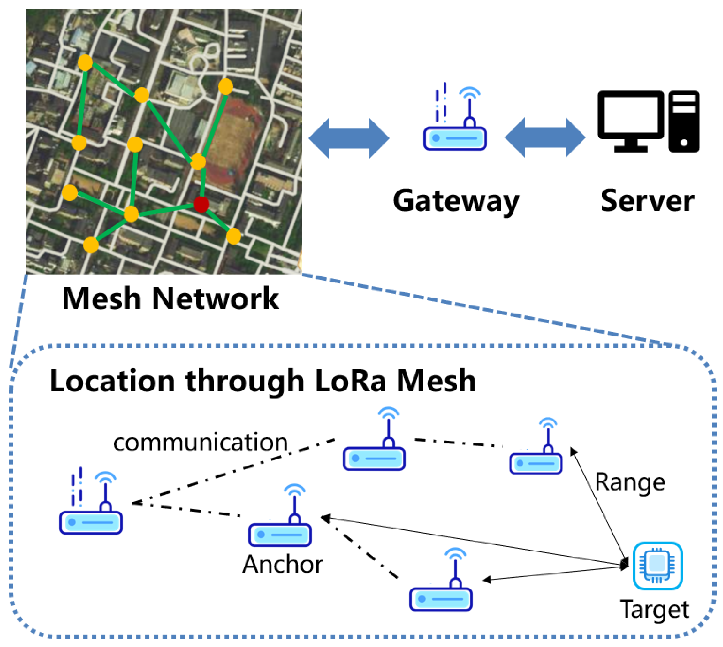
  • A wide area localization method and system based on LoRa Mesh are designed. In view of the limited radio frequency (RF) channel of LoRa hardware and the difficulty that positioning tasks and communication tasks preempt time-frequency resources, the system realizes the coexistence of communication and positioning functions by optimizing the system logic. On this basis, a demonstrable LoRa communication-positioning sensing system is built through software and hardware design. To the best of our knowledge, this is the first system capable of simultaneously running LoRa Mesh networking communication and LoRa wireless positioning tasks.
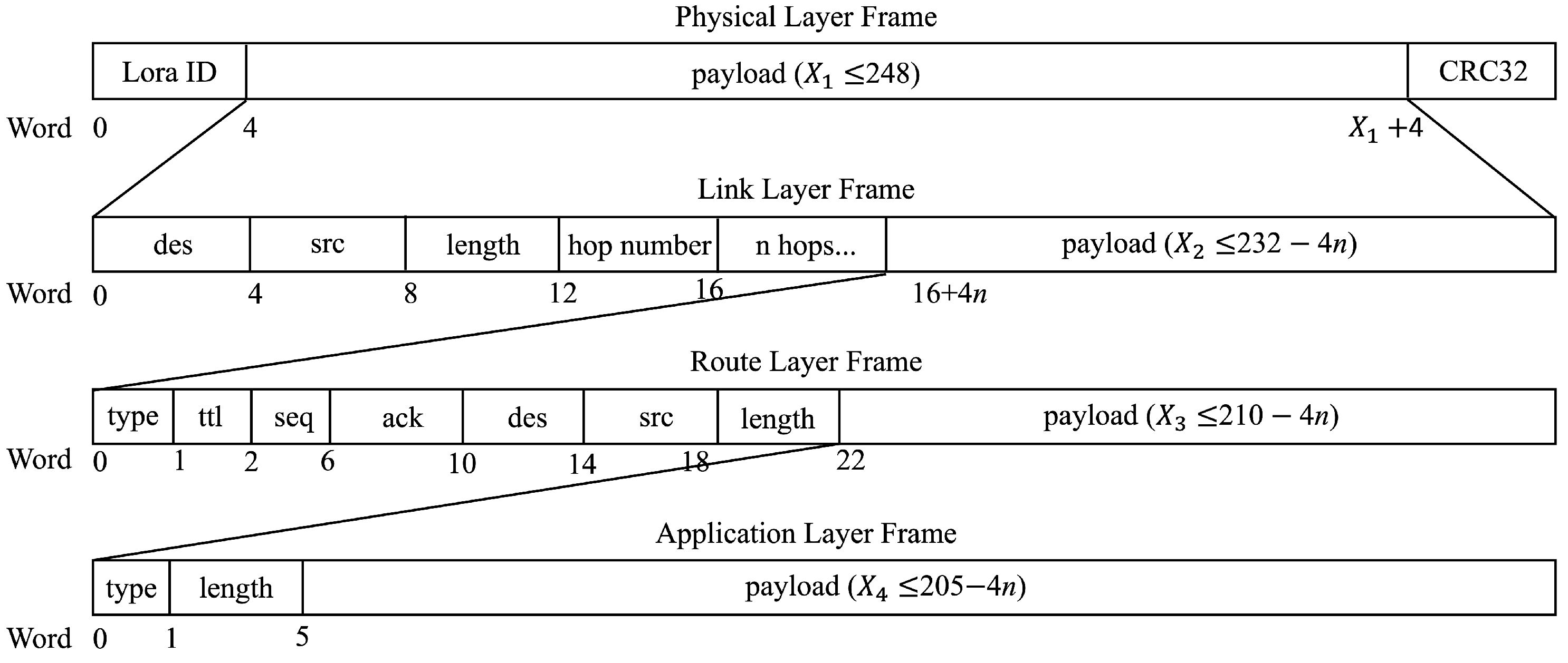
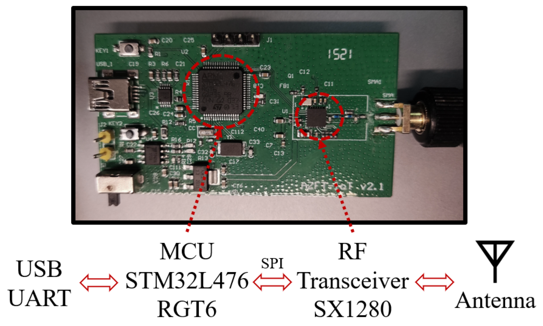
  • For hardware design, a hardware abstraction layer is added for cost control or power optimization. Moreover, a LoRa Mesh protocol with low power consumption and high reliability is designed. In view of the lack of a LoRa Mesh protocol standard, we rebuild and simplify the LoRa Mesh protocol stack and improve the packet format. Compared with other wireless Mesh protocols, the route discovery and route maintenance process of the LoRa Mesh protocol designed in this paper is simpler and more energy-efficient. The protocol also introduces the mechanism of channel activity detection and packet Cyclic Redundancy Check (CRC) check to optimize packet congestion and improve communication reliability.
  • A routing algorithm based on local link state information of nodes is designed. Under the background of limited local routing state information of nodes, the influence of communication delay, communication reliability, and node load is considered jointly, and the routing algorithm in the protocol is designed to improve the networking efficiency. The experimental results show that the proposed routing algorithm can take into account both delay and communication quality effectively compared with other routing algorithms.
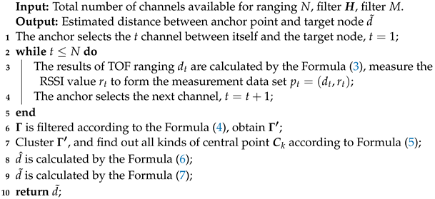
  • A distance estimation algorithm based on multi-sample data of time of flight (TOF) and RSSI is designed. Aiming at the problem that the range accuracy of LoRa is easily affected by the NLOS path propagation of signals, based on the fusion of TOF and received signal strength indicator (RSSI) data obtained by multi-beat sampling, the line-of-sight channel, and non-line-of-sight channel are screened by clustering idea, and the line-of-sight (LOS) channel is found and the distance is estimated. The experimental results of distance measurement in outdoor scenes show that the average distance measurement error of this algorithm is about 6 m.
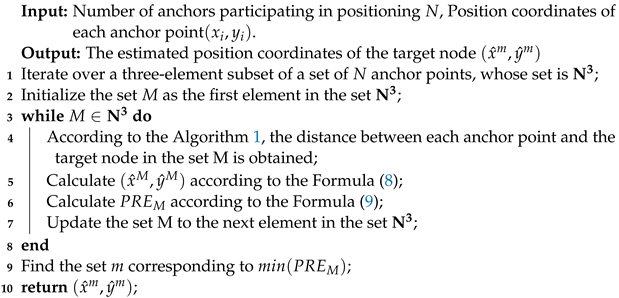
  • A position estimation algorithm is designed to minimize the posterior RSSI error. By calculating the posterior RSSI error of position estimation coordinates, an evaluation criterion of position estimation results is designed. Based on this criterion, a heuristic anchor point selection method is designed to reduce the interference of bad anchor points and improve the accuracy of the position solution. Experimental results in outdoor scenes show that the proposed algorithm can provide meter-level positioning accuracy when the regional anchor point density is high.
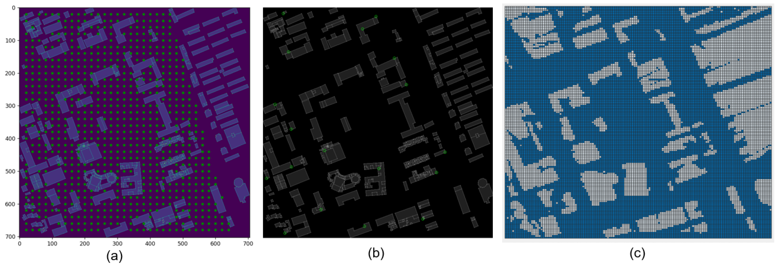
  • The optimal position of the anchor point is discussed. In order to solve the problem of lack of reference basis for anchor location, electromagnetic simulation is used to simulate the spatial signal distribution, and a heuristic anchor location selection algorithm is designed based on the spatial signal distribution and a priori knowledge to find the best anchor location with the best coverage effect.

2. Literature Review

In this section, we introduce research studies on LoRa networking and LoRa localization, and analyze the limitations of these existing works.

2.1. LoRa Primer and Its Mesh Networking

LoRa is a kind of radio modulation technique using a proprietary spread spectrum modulation that is a derivative of chirp spread spectrum (CSS). According to the operating frequency band, LoRa can be divided into LoRa sub-GHz and LoRa 2.4 GHz. LoRa Wide Area Network (LoRaWAN) is a star network protocol based on LoRa sub-GHz. Currently, there is no LoRa 2.4 GHz network protocol.
The research on LoRa networking mainly focuses on LoRaWAN. LoRaWAN is a star network with mature standards. The existing research mainly focuses on analyzing the standard LoRaWAN protocol and discussing how to mitigate the issues caused by signal attenuation and collisions in high-density wireless devices [11,12].
However, LoRaWAN does not have a mechanism for controlling frequency band selection to simplify device control layer design, reduce device power consumption, and consequently extend the battery life of battery-powered devices. Additionally, LoRa devices can transmit data to gateways at any time, causing severe packet collisions if multiple devices transmit signals simultaneously. This limitation restricts the outdoor deployment of LoRaWAN. In reference [13], the authors have found that the available uplink capacity of devices in LoRaWAN is related to the distance to the gateway and the number of devices connected to the gateway. In scenarios with a high number of gateway-connected devices, the uplink capacity may drop to an average of 100 bits per second. Moreover, in LoRaWAN, the lack of a clear channel assessment mechanism increases the probability of data packet collisions, and in high-density LoRa device environments, the data packet delivery rate can drop to 25% [11]. Another study [14] also points out that under significant path loss, star networks have a 30–70% higher packet loss probability compared to mesh networks.
To address the shortcomings of LoRaWAN, a LoRa Mesh network system is proposed and its performance is evaluated [15]. However, current research on LoRa Mesh has not adequately addressed data congestion issues and has not conducted in-depth research on routing selection and related problems. In recent years, the LoRa network has been applied to the fields of animal rescue [16], environmental detection [17], industrial production [18], and so on. However, these applications of the LoRa network are limited to the field of data transmission and are not effectively combined with LoRa positioning technology for wide area positioning and tracking.

2.2. LoRa Localization

Due to LoRa’s characteristics of low power consumption, low cost, wide coverage, and large connection, many researchers have applied LoRa to location-based tasks which are not sensitive to time delay. Muller et al. [19] has made statistics on the ranging error of the LoRa signal and pointed out that LoRa has the ranging capability within kilometers. A comprehensive characterization of the LoRa signal and an evaluation of its real location service is presented in reference [20]. On this basis, a series of positioning methods based on LoRa are proposed, which can be roughly divided into two categories: Time Difference of Arrival (TDOA) based positioning methods and RSSI based positioning methods.
The principle of the TDOA-based positioning method is to determine the location of a device by measuring the time difference between the arrival of the same signal at multiple gateways. There are currently three main methods for extracting LoRa signal timestamps: (1) reading timestamps provided by LoRaWAN gateways, (2) estimating arrival times in the frequency domain, and (3) estimating arrival times in the time domain. However, due to the 1-microsecond resolution of current LoRa hardware and software stacks, these methods can only achieve microsecond-level timestamp precision. As a result, their positioning performance is relatively poor since radio signals can propagate approximately 300 m in 1 microsecond in free space, making these methods insufficient for precise localization. Many TDOA-based LoRa positioning systems rely on timestamps provided by LoRa gateways, leading to suboptimal positioning accuracy [21,22,23]. On this basis, Lam et al. [24] remove bad anchor nodes or selects well-performing anchor nodes in the positioning process to reduce the impact of non-Gaussian noise on the LoRa network, and proves that the positioning accuracy of the LoRa system can be comparable to that of the GNSS with a sufficient number of anchor nodes. In order to improve the precision of LoRa positioning, some researchers have utilized highly customized LoRa devices to achieve nanosecond-level timestamp accuracy, thereby achieving meter-level accuracy in TDOA positioning [25]. However, considering cost constraints and the need for widespread adoption, TDOA positioning systems developed based on generic LoRa hardware still cannot address the aforementioned challenges.
Different from TDOA-based methods, the principle of the Received Signal Strength Indication (RSSI)-based localization method is to establish a path loss model based on the measured RSSI at different distances from the signal source. In the RSSI-based ranging algorithm, nodes use a known signal propagation model to characterize the relationship between RSSI and distance. They estimate the distance to the signal source based on RSSI measurements. Finally, by utilizing distance information obtained from multiple positioning anchor nodes, the coordinates of the target node are calculated [26]. Many RSSI-based LoRa positioning products have been developed [26,27,28,29,30]. To improve positioning accuracy, researchers have conducted studies in areas such as correcting the RSSI path loss model, mitigating multipath interference, and noise suppression. Regarding path loss model correction, He et al. [31] model RSSI in indoor and outdoor environments using Gaussian processes and then develop a localization method through maximum likelihood estimation. In reference [32], terrain parameters are introduced to correct the accuracy of the traditional RSSI model. In reference [33], DeepLoRa employs remote sensing to automatically identify land cover types along LoRa links, and then utilizes deep learning to estimate the path loss in complex environments. In reference [34], SateLoc uses satellite images to recognize land cover types and generates virtual fingerprint databases for each gateway based on the path loss parameters corresponding to different land cover types, enabling positioning through fingerprint matching. However, these methods still have significant errors or require auxiliary information, such as satellite remote sensing, making them less suitable for general deployment. In terms of suppressing multipath interference and noise, an improved RSSI ranging output algorithm based on Wiener filtering is proposed, effectively reducing noise interference and achieving more accurate ranging and positioning [35]. To combat multipath interference, an amplitude-based anti-multipath method is proposed in reference [36], achieving 4.6 m accuracy in indoor settings, but requiring specially designed antennas. To avoid multipath interference, a large-scale outdoor fingerprint database is built in reference [37], enabling high-precision positioning, but facing challenges such as fingerprint aging and deployment migration. In reference [38], the authors achieve high-precision positioning with an error less than 10 m in a 50 m × 50 m × 22 m outdoor 3D space, combining RSSI fingerprints and path loss models. However, this method also requires extensive prior information for building the fingerprint database. Overall, RSSI-based LoRa positioning technology is susceptible to multipath effects, and its accuracy depends on the number and deployment locations of anchor nodes.
The above-mentioned localization techniques are based on LoRa sub-GHz development, and their positioning accuracy is limited due to the restricted signal bandwidth. In recent years, a series of localization techniques based on LoRa 2.4 GHz have been developed, which utilize high-precision TOF ranging to reduce outdoor positioning errors to below 5 m [19,39]. However, these LoRa 2.4 GHz-based localization techniques still struggle to overcome the interference caused by multipath effects.
Currently, most of the research on LoRa positioning is based on a small number of LoRa positioning devices, resulting in limited coverage of outdoor areas. With the demand for outdoor wide-area positioning, a positioning system would require a large number of LoRa positioning devices, which should be interconnected wirelessly through the LoRa network. However, the application of LoRa networks has been mainly focused on data transmission, and the research on providing positioning services using the LoRa network is still immature. LoRaWAN, as the mainstream LoRa network technology, has been discussed by a few researchers for outdoor positioning systems. In reference [40], a LoRaWAN system consisting of 68 positioning devices was built, covering the city area of Antwerp. The positioning was achieved through fingerprinting, with an average positioning error of 398.4 m. The RSSI test dataset of this system has been made open-source, and some researchers used deep learning and fingerprinting methods to reduce the average positioning error to 381.8 m [41] and 340 m [42], respectively. In reference [43], a fusion of RSSI and timestamp data reduced the average error to 322.6 m using the same dataset. In experiments with a public outdoor LoRaWAN network in the Netherlands, a TDOA-based positioning error of 150 m is obtained [44]. Similarly, in the Netherlands’ public LoRaWAN network experiment, an average positioning accuracy of 82 m is achieved using a TDOA-based method [23]. Furthermore, TDOA multipolarization positioning in a 2 × 3 km area using four positioning devices is realized with an average error of about 100 m [21]. Additionally, experiments using four positioning devices in an open outdoor area of 340 m × 340 m is conducted with an average error of 24.1 m [45].
Although the outdoor positioning accuracy based on LoRaWAN is continuously improving, the existing research’s positioning precision still falls short of meeting the practical positioning tasks’ requirements. This is because LoRaWAN’s signal power is relatively low, making it susceptible to strong signal attenuation, resulting in significant system positioning errors [10]. Most works reduce positioning errors by limiting their solutions to specific settings (e.g., very small area coverage, fixed devices, controlled test durations, etc.). Therefore, to enhance outdoor positioning capabilities based on LoRa networks, it is necessary to increase the density of positioning devices within the area, enhance the network’s reliability and scalability, and provide more options for positioning algorithms. Compared to the single-hop topology of LoRaWAN, outdoor positioning systems based on LoRa Mesh have greater potential.
Due to the early stage of research, there have been few attempts to use LoRa Mesh networks for positioning. In reference [46], a star network and RSSI-based positioning method were used for parking lot positioning. However, it has drawbacks such as low spectrum efficiency, the need for prior knowledge of parking spaces, and limited coverage range of the star network. In the paper [47], a hybrid network combining LoRaWAN and Mesh was used for urban environment positioning. However, its positioning functionality was achieved through GNSS and is only suitable for devices with an external power supply. These systems are early attempts at using LoRa Mesh for outdoor positioning and still face various challenges. Integrating large-scale LoRa Mesh networks with positioning algorithms to achieve outdoor wide-area positioning in urban environments still faces many challenges that need to be addressed. Currently, there is no unified standard for the LoRa Mesh protocol, and existing LoRa positioning algorithms heavily rely on the deployment locations of anchor nodes. Furthermore, the problems of how to overcome the interference of the multipath effect and how to achieve a larger range of locations through a LoRa network with low power and low cost have not been effectively solved.

3. System Overview

This section introduces an overview and practical challenges of LoRaWAPS. LoRaWAPS plans to deploy a large number of low-cost, low-power positioning anchors which are networked using the LoRa Mesh protocol. Through the coordination of a large number of anchor points, full signal coverage is provided for the region to avoid larger positioning errors caused by poor signal quality. The system architecture is shown in Figure 1. The system consists of a server, a gateway, a number of positioning anchors, and a number of targets.
Tags are used to track the locations of goods or persons. The tag is portable and has long battery life. It is equipped with a large-capacity battery that can last for several years with a single charge. The tag weighs less than 100 g. LoRa technology enables wireless communication and ranges between tags and positioning anchors.
Location anchors are placed within the region. The location coordinates of the anchors are known to the server. The wireless networking among anchor points and gateways is completed through LoRa Mesh protocol. Distance information can be obtained by TOF ranging between the anchor point and the tag. Data packets such as distance information and task instruction between the anchor point and the tag are transmitted bidirectionally between the gateway and the anchor point through wireless mesh networking. The anchor can be powered by solar energy or its own integrated large-capacity battery instead of external power sources. Therefore, external power cables and network cables are not required for anchor deployment.
The gateway is the source node in the entire LoRa Mesh network. It communicates with anchor points and tags through the wireless network, and is also connected to the server through wired access, playing the role of uploading and transmitting.
The server is the “brain” of the system, which grasps the position coordinates and links state information of all anchor points. The server sends the ranging instruction to the anchor point and label through the gateway, receives the ranging result from the anchor point and label through the gateway, and estimates the location coordinates of the label based on collected data.

4. System Design

In this section, the design of the system is described. We first present the design of the hardware and then illustrate the details of the mesh networking. Finally, the ranging and localization algorithms are proposed.

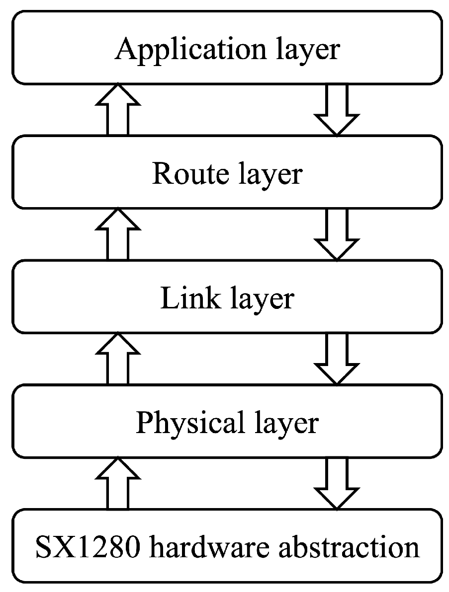
4.1. Hardware Design

The system consists of gateways, anchors, and targets. The gateway and anchor consist of a LoRa radio module, a control module, an interface module, a low noise amplifier (LNA), and a high-gain antenna. The hardware structure of the target is much the same as the anchor, except that the LNA is removed, as shown in Figure 2.
The radio module uses the SX1280 chip. SX1280 is an RF-integrated chip developed by SEMTECH, which can carry out ultra-long distance communication in the 2.4 GHz band with linearity and can withstand severe interference. The receiving gain of the low noise amplifier is 10 dB and the transmitting gain is 11 dB. It has a built-in automatic discrimination circuit for high-speed transceiver switching, which can automatically switch the transceiver state and work automatically without the control signal given by the control chip. The control module is based on STM32L476RGT6, a low-power ARM Cortex-M4 microprocessor. The control module is responsible for controlling the RF module and uploading the data and is connected to the radio module through serial peripheral interface (SPI). The interface module uses the serial port to network port chip to provide wired network access and data reporting (as a gateway).
The current design focuses on functional verification, so its size and low-power characteristics are not optimized. Despite that, all the following proposed algorithms are device-independent by adding a hardware abstraction layer, making it easy to port to other platforms for cost control or power optimization.

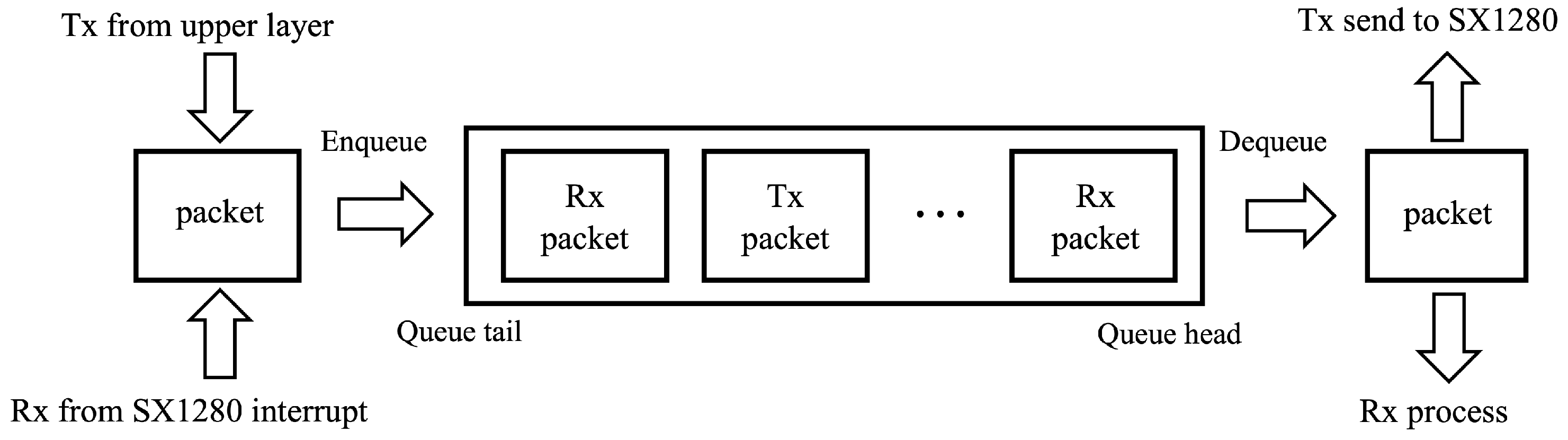
4.2. LoRa Mesh Protocol Design

In this section, the design of the mesh networking protocol is described. The mesh networking protocol is an on-demand routing protocol. It discovers and maintains routes only when data needs to be sent, effectively reducing power consumption. We also design the layered structure of the grid protocol to make it modular and maintainable. Furthermore, we propose a routing algorithm that balances efficiency and communication quality.

4.2.1. The Structure of the Mesh Protocol

The proposed mesh networking protocol consists of four layers: the physical layer, the link layer, the routing layer, and the application layer. Its architecture is shown in Figure 3.
The physical layer communicates with the hardware and guarantees network reliability at the hardware level. There is a packet queue in the physical layer, as shown in Figure 4. All sending packets and received packets will be serialized in the queue to reduce hardware conflicts while keeping the order of packets. Channel activity detection (CAD) and random delay mechanism are used in the physical layer to reduce data collisions. Specifically, the authors require the device to set CAD mode to check if the channel is occupied before sending data. CAD can detect LoRa lead codes on wireless channels. The lead code is used to keep the receiver in sync with the incoming data stream and is 12 symbols in length by default. If the channel is occupied, the device changes the channel or waits for a random period of time before sending data. In addition, 32-bit Cyclic Redundancy Check (CRC32) is also used to reduce data errors.
The link layer ensures that packets passing to the upper layers are all packets to be processed by this node. In this layer, the target and source IP are defined in this specific hop, which only represents the previous hop node and the next hop node of the packet. The node will only process the packet whose target IP is the same as its own IP or is a broadcast IP. To prevent the infinite flooding of a broadcast packet, the link layer also maintains a list of nodes traveled.
The route layer is the key layer of our mesh protocol, maintaining a route table, executing the routing algorithm, and ensuring the best-effort delivery of the packet. The route table contains information on the network collected from received packets. When a Packet is to be sent, the route layer will use the route algorithm to choose a path from the route table, and create a route layer header. We also maintain a waiting list in this layer, which is used to handle replies and re-transmit a packet if no reply is received in a specified resend interval time, a packet without a reply might be re-transmitted several times before declaring an error.
The topmost layer is the application layer, whose role is to implement functions such as sending positioning instructions, handling messages, or communicating with the host computer.
The packet structure is shown in Figure 5, each layer will add a new header. In the physic layer header, LoRa ID is used to distinguish LoRa packets that belong to our system and CRC32 is used to check the payload’s Integrity. In the link layer header, destination IP, source IP, and node IPs in this specific hop, the length field represents the payload’s length, and the hop number records the number of nodes the packet has passed through. Following the hop number filed, a list records all nodes traveled. The route layer header has seven fields, destination IP and source IP indicates the final and initial nodes which differ from those in the link layer. The application layer packet only contains the type and length field for content indication.

4.2.2. Route Discovery and Maintenance

As mentioned before, our LoRa mesh protocol is a kind of on-demand routing protocol, when there is no load in the network, all of the nodes keep silent. When there is a load, the network starts the update and maintenance process. As shown in Figure 6, when starting to transmit a message, the node will look up the route table to find a valid route to its destination. If the route exists, the packet will be transmitted following the path, if not, the node will start finding a route by sending a broadcast lookup packet. Each node that received the broadcast packet without a valid route to the destination will relay this broadcast. If received by the destination node or any node with a valid route to the destination, they will reply to the source node according to the path of the broadcast packet. After sending the lookup packet, the source node will add it to the waiting list for timeout re-transmission. Once the lookup packet reply is received, the suspended message packet will be transmitted to the destination through the discovered route.
When the network is active, each node can update its route table by capturing the packets of the surrounding nodes. Each route table entry has a valid time field, which will be refreshed by a new packet from the route path, and the RSSI field can also be updated by any captured packet. If the entry’s valid time ends, the entry will be set to be invalid. If one route entry fails on several transmission tasks, it will also be set to be invalid.

4.2.3. Routing Algorithm

After receiving the broadcast packets forwarded by multiple nearby nodes, the node to be added to the network needs to select the most suitable parent node and join the network. There are two main routing algorithms in current mesh networking protocols. One algorithm is to choose the node with the lowest signal attenuation between themselves, namely the algorithm of maximizing RSSI. The other algorithm is to select the node with the smallest hop count to the gateway, that is, to minimize the hop count. However, these two routing algorithms cannot balance communication efficiency and communication quality well. The goal of the minimal hop count networking is to reduce the hop count of routes. However, when the RSSI between two nodes is lower than −80 dBm, the link reliability deteriorates seriously, which is reflected as a high packet loss rate. The maximum RSSI algorithm selects the path that maximizes the overall RSSI value of the link, thus ensuring the quality of the connection between each hop. However, if the hop limit is not considered, the selected path may have unnecessary forwarding, which increases the transmission delay.
A heuristic algorithm is designed to find the optimal route in order to take into account node load, packet arrival rate (PDR), and data transmission time (DTT). First, LoRa broadcast packets are modified. When each node forwards broadcast packets, the hop count of the node to the gateway and the current load of the node are updated. After receiving the broadcast packets forwarded by surrounding nodes, the node to be connected to the network can calculate the attractiveness of surrounding nodes. Attractiveness can be calculated based on self-measured RSSI and the information in received packets. We define the attraction of node i to node j as:
K i , j = r i , j 2 M j T j ,
r i , j = 10 60 10 , r i , j > 60 dBm , 10 r i , j 10 , r i , j 60 dBm .
In the equations, K i , j is the attraction of node j to node i. Node i will choose a surrounding node j with the highest attraction and join it. r i , j is originally the absolute power calculated from RSSI between node i and j. Considering that if the RSSI is higher than −60 dbm, the link is already reliable enough, the authors fix the RSSI value higher than −60 dbm at −60 dbm to avoid ignoring hop count and path load due to redundant RSSI. M j is the path load on the node j, which means how many routings are forwarded through the node j. T j is the number of hops from node j to the gateway. Considering the above three factors at the same time can make the routing algorithm more reasonable and reliable.

4.3. LoRa Ranging and Localization

This section introduces how to use the LoRa Mesh network to locate and track the target. Firstly, we introduce the working flow of location, then process the ranging results of anchors and the target, and finally give the algorithm of multi-point location.

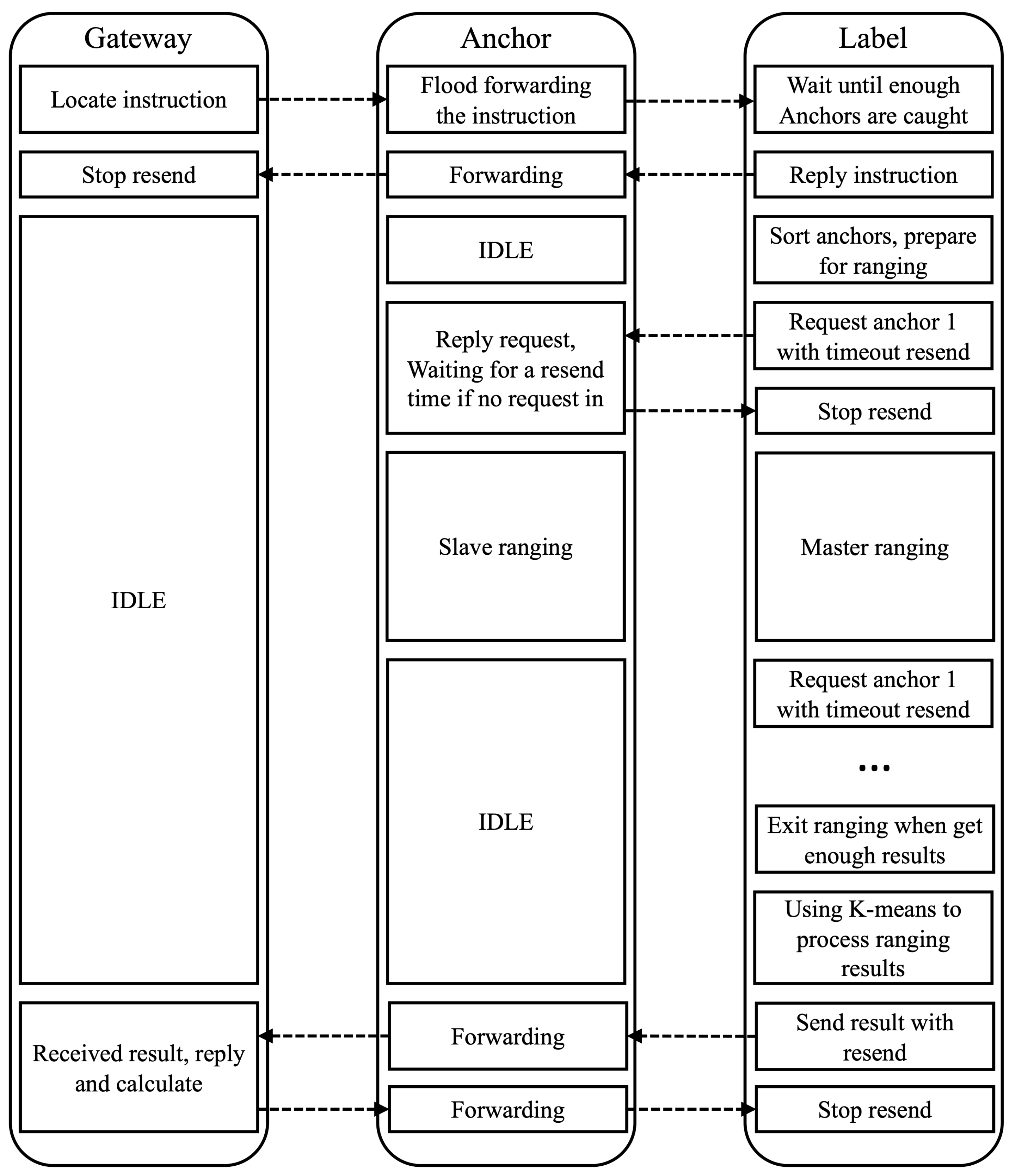
4.3.1. Positioning Workflow

It is important to note that standard LoRa hardware has only one RF channel. To carry out the ranging operation, the packet-type parameter of SX1280 should be set from LoRa to LoRa Ranging. This means that nodes cannot communicate during ranging. If the workflow of the system is not correct, some nodes in a path that is transmitting data may be in ranging mode, which will cause the data transfer to fail. Therefore, the positioning workflow of the system is very important.
We have taken mode switching of LoRa into consideration and designed the workflow of system positioning, as shown in Figure 7. The gateway sends the positioning instruction, and the anchor points in the network broadcast and forward the positioning instruction after receiving it. The target is usually in a standby state to save energy consumption. After receiving the positioning instruction, it will record the anchor information of the surrounding forwarding positioning instruction and apply it for joining the network. In the next stage, the target initiates ranging to the surrounding anchor points, until all the surrounding anchor points complete ranging, all the results are sent to the gateway, and the target returns to the standby mode.
Since the target may be moving, they need to find the anchor node currently around before each ranging. Therefore, the authors broadcast location instructions to the node. When the target receives a broadcast location instruction for the first time, it updates the routing table and collects all broadcast instruction packets from the neighbor node. If the number of nodes around is enough to obtain location results, the label responds to the gateway and starts its ranging work.
Figure 7 also shows that, during ranging, the target acts as the master role, and the other anchors act as the slave role. This is because only the target knows the link status information of all surrounding anchors. The target records the corresponding RSSI value when receiving broadcast packets from surrounding anchors and sorts the anchors in order of RSSI value. The target will preferentially range anchors with good signal quality (high RSSI value). At the beginning of ranging with one anchor, the target sends a ranging request to the anchor and waits for the reply. If no reply is received within the resend interval time, the target will resend the packet. For anchors, if it receives a ranging request from the target and is ready for the ranging, it replies to the target directly and waits for a resend interval time to listen if a ranging request comes again, which avoids the loss of reply. If target receives the right reply to the request, it switches to the ranging master mode, and will take an extra resend interval time for the anchor to switch to ranging slave mode. Both the master mode and slave mode have a timeout exit mechanism if no action takes place.
For anchors that are far away from the target, communication or positioning of other targets can be carried out as usual, so that the whole system can carry out both communication and positioning tasks at the same time.

4.3.2. Ranging Algorithm

The positioning function of LoRaWAPS is based on the ranging result of anchors and targets. Therefore, it is very important to process the ranging data to make the distance estimation more accurate.
The Semtech SX1280 transceiver has a built-in ranging engine, which performs time-of-flight measurements between a pair of transceiver radios. The distance between the master node and the slave node can be calculated according to the result of the timer:
d = N c 2 12 B .
In the equation, N is the result of the timer, B is the transmission bandwidth in Hz , and c is the speed of light.
We first perform ranging operation and ranging correction according to Semtech SX1280 datasheet [48]. To improve distance measurement accuracy, ranging is carried out on 40 different channels successively, and timeout re-transmission and exit mechanisms are used to cover as many channels as possible.
TOF and RSSI for 40 channels can be obtained. Firstly, we filter the TOF data to eliminate the extreme cases in the data. Then, the RSSI data is filtered and the corresponding data of the channel with large signal attenuation is removed. Secondly, considering the influence of signal refraction and other non-Gaussian noises, the authors propose to use the K-Means clustering algorithm to divide NLOS and Line of Sight (LOS) results. K-Means is a clustering algorithm based on the division of sample sets. We cluster the data of the remaining channels into multiple clusters, in which each cluster corresponds to the data of different channels. The center point of the cluster corresponding to the LOS channel has the minimum TOF value. We then average the results classified as LOS channels to obtain the output. Finally, because the drift of the LoRa hardware clock will lead to the deviation of frequency, some nonlinear results will appear in the close-range measurement, leading to the decrease in distance estimation accuracy, which needs to be corrected [49]. The ranging algorithm is shown in Algorithm 1.
First of all, assume the data of the t-th channel is defined as p t = ( d t , r t ) , d t is the TOF ranging data calculated according to Formula (3), and  r t is RSSI value. Γ = p 1 ( Γ ) , p 2 ( Γ ) , , p N ( Γ ) ( Γ ) represents a set of data and p n ( Γ ) is an element of the set. Filter H is used for data line filtering. Filter H can be a median filter, mean filter, or other similar filter.
Γ H Γ .
Secondly, considering the influence of signal multipath propagation and other non-Gaussian noise, K-Means clustering is used to divide the data in the dataset Γ into M classes. C k represents a cluster resulting from K-Means clustering. p c k represents the center point of the cluster C k .
p c k = E ( C k ) ,
d c k and r c k are the TOF ranging data and the RSSI value in the center point p c k . Find the cluster that has the minimum ranging distance d c k , the data corresponding to the line-of-sight channel can be extracted.
d ^ = m i n k   d c k ,
where d ^ is the estimated distance.
Finally, the estimated distance is modified to obtain the final result d ˜ .
d ˜ = d ^ , d ^ > 100 m , γ d ^ + ( 1 γ ) 10 r 0 r ^ 10 n , d ^ 100 m .
Among them, γ is selected by experimental analysis, n is the road loss parameter, and r 0 represents the RSSI value at a distance of 1 m.
Algorithm 1: Distance estimation algorithm based on TOF-RSSI fusion clustering
Applsci 13 09501 i001

4.3.3. Location Algorithm

With multiple distance information from moving target to stationary anchors with known coordinates, the authors are able to solve coordinates target. The classic three-point positioning method is usually adopted. Assume that the coordinates of the three selected anchor points are ( x a , y a ) , ( x b , y b ) , ( x c , y c ) , the ranging results between the LoRa tag and the three anchors are ( d ˜ a , d ˜ b , d ˜ c ) , and  ( x ^ , y ^ ) represents the estimated LoRa tag position coordinates. The optimal ( x ^ , y ^ ) is obtained using the iterative method, which minimizes the ranging error f ( x , y ) = i = a , b , c d ˜ i x i x ^ ) 2 + ( y i y ^ ) 2 2 . The expression of the k + 1 iteration is written as:
x ^ k + 1 = x ^ k f x ^ k , y ^ k · f ( x , y ) x x = x ^ k , y = y ^ k 1 , y ^ k + 1 = y ^ k f x ^ k , y ^ k · f ( x , y ) y x = x ^ k , y = y ^ k 1 .
Since the true position of the target is unknown, it is impossible to know the positioning error after positioning, so we cannot directly optimize the positioning performance. However, since the RSSI measurements of all anchors to the targets and the estimated location of the target are known, the performance of positioning can be heuristically estimated by comparing the difference between measured and calculated RSSI using the estimated location of the target. Therefore, the posteriori RSSI error (PRE) between the anchor and the target is defined to evaluate the anchor positioning capability as:
P R E i = ( r i r ^ i ) ,
where r i = r 0 10 α log 10 d ^ i denotes the wireless signal strength calculated according to the estimated position. r 0 is the radio signal intensity at an interval of 1 m. Based on the above heuristic, the location algorithm is shown in Algorithm 2.
Firstly, M different sets are selected from the ranging data of N anchor points to the target obtained, and the location of anchor points ( x ^ M , y ^ M ) is estimated according to the method in Equation (8). Secondly, calculate the mean PRE of each anchor point corresponding to each ( x ^ m , y ^ m ) according to Equation (9), m M . Finally, ( x ^ m , y ^ m ) corresponding to the set m with the minimum mean PRE is selected as the positioning result.
Algorithm 2: Multi-point location algorithm based on minimizing posteriori error
Applsci 13 09501 i002

5. Implementation

In this section, we introduce the implementation of LoRaWAPS, including the designing of the control interface and visualization and the optimization of anchors deployment.

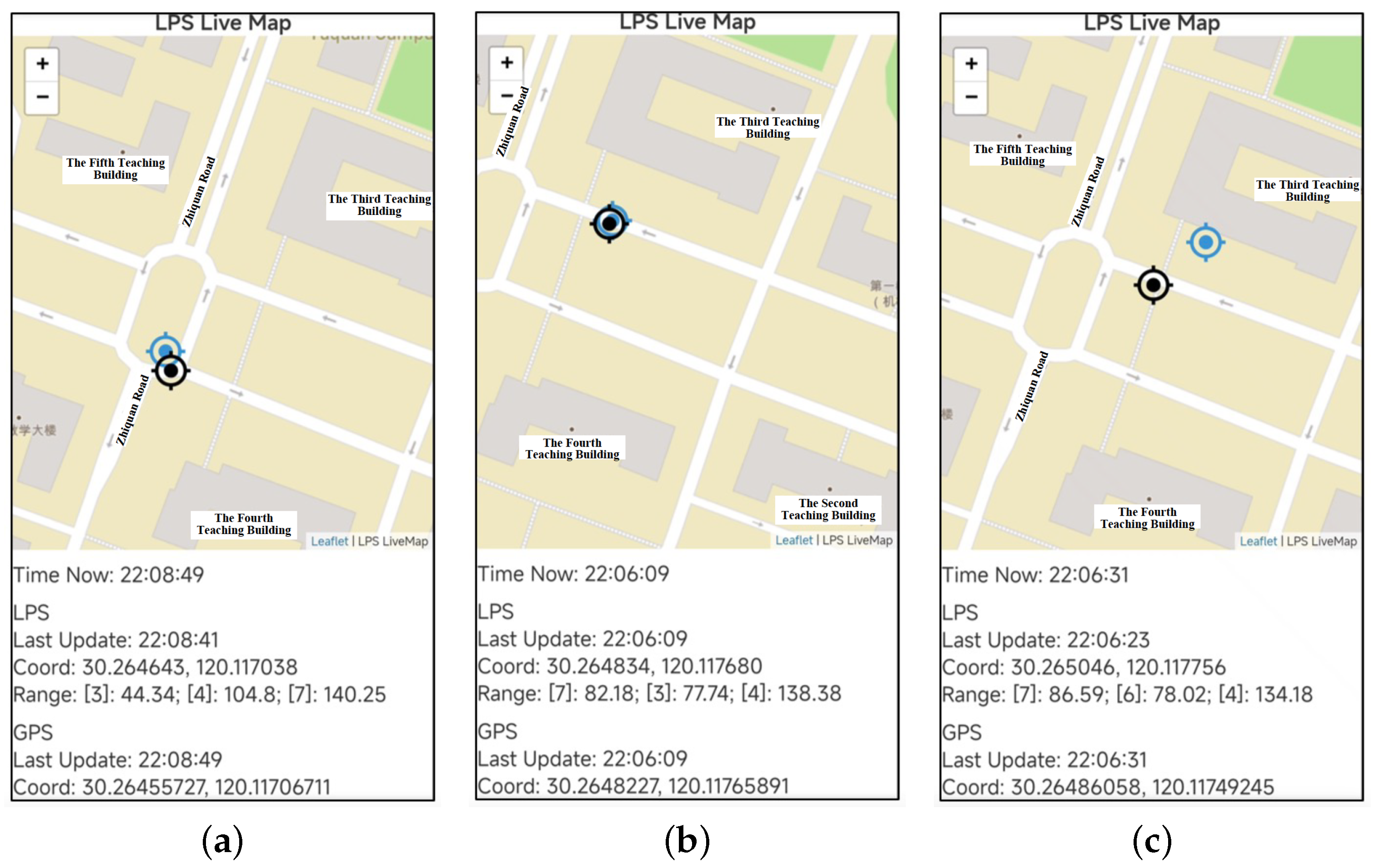
5.1. Control and Visualization Interface

For the control of the system, an control interface is designed, as shown in Figure 8. We can connect the host computer running the Python script to an arbitrary node in the mesh network through a USB serial. When the Python script receives an input command, it will process it and send further commands to the node. The node will uni-cast or broadcast the command according to the command type, so the command can be received by one or all nodes in the mesh network. Replies received by the node will be sent back to the host computer. In particular, localization results are produced to a Kafka topic data stream. A web page will consume that data and visualize them on a map. Global Positioning System (GPS) data for experiment use can also be collected from an Android device with a custom app and uploaded to be shown on map.

5.2. Anchors Deployment

We deploy the system in the Yuquan Campus of Zhejiang University. In the actual deployment of the system, the selection of the most appropriate anchor location is considered to better cover the positioning blind area. With the help of electromagnetic simulation software, the signal intensity of anchors at different positions can be generated to help evaluate the coverage ability of anchors.
The actual deployment requires the coverage area to receive stable signals from at least three anchor points ( R S S I 85 dBm). Through the heuristic algorithm, we hope to use as few anchor points as possible to provide positioning ability covering Yuquan Campus. The proposed algorithm is shown in Algorithm 3.
As shown in Figure 9a, we assume several locations l n where anchors can be placed at intervals of 5 m. Specifically, the green dots in the figure indicate the location of chosen anchor points. Then, we convert the spatial grid into grids spaced 1 m apart and calculate the signal intensity of the anchor placed at position L n on all grid points, denoted as S n . The member s j n of the set S n denotes the signal strength of the anchor placed at the n-th point at the j-th lattice point. Its value is obtained by electromagnetic simulation software. At this point, each position l n in the set L can place anchors. c j represents the signal coverage quality at the j-th lattice point, which is 0 data when there is no signal.
Then, suppose that after placing an anchor point at l n ,
c j ( n ) = c j + 1 , s j n > 85 dBm & c j < 3 , c j , e l s e .
Next, find n 0 for maximizing C ( n ) ,
C ( n ) = j ( c j ( n ) c j ) .
Move n 0 out of set L and add it to set L , whose elements indicate where to place the anchor.
c j = c j ( n 0 ) .
Finally, repeat steps 2 to 3 until a set L of k elements is found, the set L represents the lattice points where the optimal k anchor points are placed.
Algorithm 3: LoRa anchors optimization deployment algorithm
Applsci 13 09501 i003
Based on the above algorithm, numerical experiments in the Yuquan Campus of Zhejiang University were carried out. Firstly, a number of green grid points 5 m apart are marked on the map to indicate the alternative anchor position, as shown in Figure 9a. We found that only 18 anchor points could be deployed to provide a stable location service capability for the entire outdoor area of the campus. The green dots in Figure 9b indicate where the anchor points should be placed. Figure 9c shows the signal coverage capability when 18 anchor points are placed. The blue area in the figure indicates that positioning signals from more than three anchor points can be received. The white area that cannot provide positioning services corresponds to the building area.

6. Evaluation

This section reports on how our system is performed in real-world environments. We demonstrate the ranging capabilities of LoRaWAPS in Section 6.1 and the positioning capabilities of LoRaWAPS in Section 6.2. During actual experiments, we use smartphones of Honor 30 Pro+ or OPPO Ace, with operating systems of Harmony OS or Android 12, and processors of Huawei Kirin 990 or Snapdragon 865. The mobile devices are mounted on the surface of buildings or on tripods. The height of them being mounted is about 1.7 m.

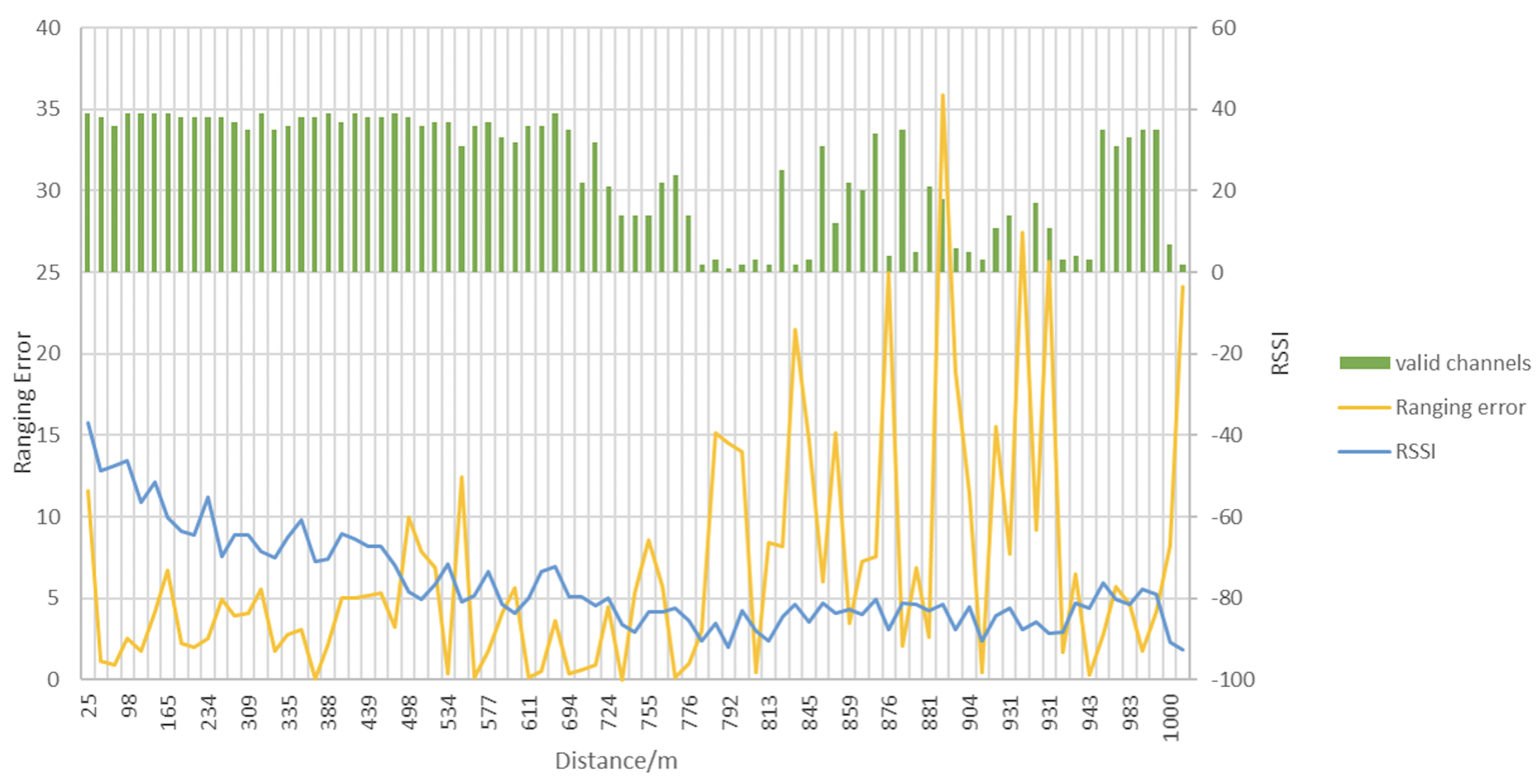
6.1. Ranging Experiment

We first evaluated the transmission capability of the LoRa signal. We conducted outdoor ranging experiments using standard LoRa hardware, the specifications of which are described in Section 4. The LoRa hardware tried 40 channels per ranging, and not every channel was successful. The quality of the signal and the effect of ranging can be evaluated by recording the number of successful ranging channels at different distances. We also recorded the RSSI in each experiment, and calculated the ranging error from the ranging result and the GPS result.
In the experiment, the working mode of master-slave TOF ranging was adopted, the spread factor SF = 6 and the transmission power was 20 mW. This experiment was carried out between two nodes on a straight and relatively clear road, ranging was performed approximately every 25 m, the result was then filtered and evaluated as shown in Figure 10.
In Figure 10, the horizontal axis indicates the distance between two LoRa devices. The green bar chart shows the number of successful ranging channels, which decreases gradually as the distance increases. The left vertical coordinate indicates the ranging error at different distances, corresponding to the yellow curve, while the right vertical coordinate indicates the RSSI at different distances, corresponding to the blue curve. As the distance increases and the signal quality decreases, the RSSI value decreases gradually, and the measurement error increases. RSSI and ranging errors are not only affected by distance, but also by non-Gaussian noise such as multipath, so the curves in the figure are not monotonically changing. All in all, LoRa’s ranging ability is strong, the ranging distance reaches up to 1000 m. The ranging error is below 15 m. In particular, LoRa’s ranging capability is excellent up to 500 m without shading, which provides a good basis for location services.
Next, we evaluated the proposed ranging algorithm. Other mainstream LoRa systems were compared in the experiment [35,49]. In the experiment, the LoRa anchor was placed at a high point in the center of a square area with a side length of 200 m. The target was measured at 30 different locations in the area. We recorded the errors between the ranging results and the actual distance in each experiment. The cumulative distribution function of ranging errors is shown in Figure 11.
In the figure, the blue lines represent our proposed ranging method with an average error of 6.46 m, 75% of which are less than 10 m. The other two mainstream LoRa systems have ranging errors of 11.48 and 13.58 m, respectively. They use the mean filter or Kalman filter to reduce the influence of noise on the ranging results, but can not overcome the interference of non-Gaussian noise caused by the multipath effect. The proposed method overcomes the influence of the multipath effect by clustering on the basis of filtering, and is proved to be effective by experiments.

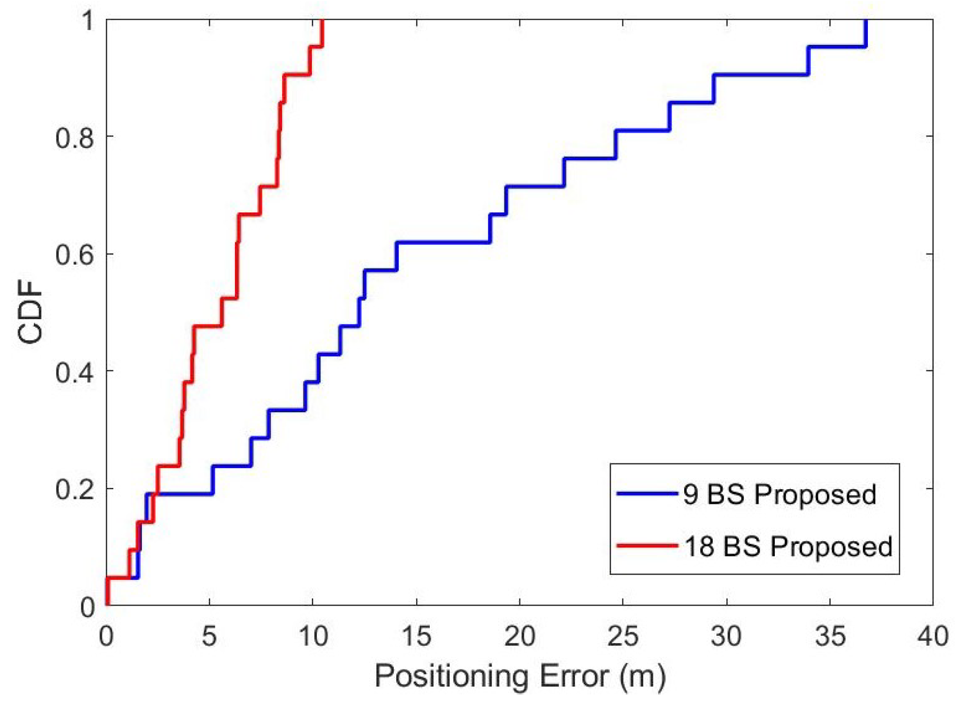
6.2. Positioning Experiment

Based on the previous steps, this section evaluates the positioning performance of the system.
In the experiment, a total of 9 LoRa anchor points were placed in a square area with a side length of 500 m. The locations of the anchor points were determined according to the proposed anchor point deployment algorithm. Nine anchor points were networked by wireless mesh, 30 different positions of the target were located in the region and the positioning errors were recorded. The bandwidth, spread factor, and other parameters of the system are the same as those of the ranging experiment. We compare the mainstream LoRa positioning system, which uses all anchor points for position calculation [24]. The cumulative distribution function of positioning errors is shown in Figure 12.
In Figure 12, the red line represents the positioning error of LoRaWAPS, with an average error of 14.49 m and 70% of the errors being less than 20 m. The blue line corresponds to the positioning error of the system in reference [24], with an average positioning error of 33.93 m. Thanks to the improvement of the ranging algorithm and positioning algorithm, LoRaWAPS shows better positioning performance. However, there is still quite a large area of poor signal quality due to the occlusion of buildings, trees, and vehicles, leading to low ranging and positioning accuracy (larger than 10 m).
To investigate the effect of the density of LoRa anchor points on positioning performance, 18 anchor points are deployed in the same square area with a side length of 500 m to achieve better signal coverage. Other settings are the same as in the previous experiment. The cumulative distribution function of positioning error for different anchor point densities is shown in Figure 13.
In Figure 13, the red lines represent the positioning errors of the system when 18 anchor points are deployed. The average positioning error is less than 5 m, and the maximum positioning error is less than 10 m. Considering that the positioning error with civil GPS as a reference is about 5 m, it can be considered that the positioning capability of the proposed system is close to GPS when the deployment density of anchor points is high.
Finally, system-level experiments were conducted to prove that all parts of the system can run smoothly. We have deployed LoRaWAPS in the Yuquan Campus of Zhejiang University, with a total of 21 anchor points, covering an area of approximately 0.25 km 2 within the campus. The experimental area where we collected data is surrounded by buildings that are mostly below 50 m in height. In order to evaluate the real-time positioning accuracy of the LoRaWAPS, the presenter moved freely within the campus with a target node and a mobile phone with satellite positioning capability. The mobile phone recorded the GPS coordinates in real time and uploaded them to the server. LoRaWAPS located the target node through anchor points and uploaded the location results to the server as well. The presenter can access the server via a web page to compare the GPS positioning results with LoRaWAPS positioning results in real time. The web page is shown in Figure 14.
In Figure 14, blue circles represent LoRaWAPS location results and black circles represent GPS location results. At the bottom of the map, time, position coordinates calculated by LoRaWAPS, anchor numbers involved in positioning in LoRaWAPS, ranging results of each anchor, and position coordinates provided by GPS, are displayed successively in real time. It can be seen that in most cases, the positioning error of LoRaWAPS is within 15 m. This accuracy is acceptable for most IoT location scenarios. If higher positioning accuracy is needed, simply increase the density of anchor deployment in exchange for better signal coverage.

7. Conclusions

In this paper, LoRaWAPS, a low-cost and low-power outdoor positioning system with multi-anchor wireless mesh networking and multi-dimensional data fusion is designed based on LoRa technology. A hardware platform for LoRaWAPS is designed and built, based on which, a low-power on-demand routing protocol is designed to realize mesh networking between nodes, and compared with other wireless mesh protocols, the route discovery and route maintenance process of LoRa Mesh protocol designed in this paper is simple and more energy-efficient. Furthermore, a distance estimation algorithm for TOF and RSSI data fusion and a position estimation algorithm for minimizing the posterior of RSSI errors are designed for LoRaWAPS. The experimental results show that the designed outdoor positioning system based on LoRa Mesh utilizing low-cost and low-power hardware can achieve high-precision positioning through the wireless mesh, enabling multiple anchor points to work together and reducing the interference caused by multipath effects, making it convenient for applications such as outdoor warehouse goods tracking, personnel management, and remote grazing in emerging IoT scenarios.
However, due to the increasingly complex and dynamic outdoor environment and the limited frequency band resources, the current systems cannot meet the actual needs of future outdoor wide-area positioning with low power consumption and low cost. In future, we will design the positioning system by improving anchor point structures with integrated multiple antenna technologies for angle and distance measurements in stereoscopic scenes, realize multi-target real-time localization with limited spectrum resources by efficiently allocating spectrum resources and avoiding interference among users, and achieve indoor and outdoor fusion positioning by designing indoor–outdoor scene switching and positioning data fusion algorithms.

Author Contributions

Methodology, B.L. and Y.X.; Software, Y.X.; Validation, B.L. and Y.X.; Investigation, B.L., Y.X. and Y.L.; Writing—original draft, Y.X.; Writing—review & editing, Y.L.; Supervision, Z.S.; Funding acquisition, Z.S. All authors have read and agreed to the published version of the manuscript.

Funding

This work was supported by the Open Research Project of the State Key Laboratory of Industrial Control Technology, Zhejiang University, China (No. ICT2023B25) and the National Natural Science Foundation of China (No. U21A20456).

Data Availability Statement

No new data were created or analyzed in this study. Data sharing is not applicable to this article.

Conflicts of Interest

The authors declare no conflict of interest.

References

  1. Zafari, F.; Gkelias, A.; Leung, K.K. A Survey of Indoor Localization Systems and Technologies. IEEE Commun. Surv. Tutor. 2019, 21, 2568–2599. [Google Scholar] [CrossRef]
  2. Li, Y.; Zhuang, Y.; Hu, X.; Gao, Z.; Hu, J.; Chen, L.; He, Z.; Pei, L.; Chen, K.; Wang, M.; et al. Toward Location-Enabled IoT (LE-IoT): IoT Positioning Techniques, Error Sources, and Error Mitigation. IEEE Internet Things J. 2021, 8, 4035–4062. [Google Scholar] [CrossRef]
  3. Ramadan, M.; Sark, V.; Gutierrez, J.; Grass, E. NLOS Identification for Indoor Localization using Random Forest Algorithm. In Proceedings of the WSA 2018, 22nd International ITG Workshop on Smart Antennas, Bochum, Germany, 14–16 March 2018; pp. 1–5. [Google Scholar]
  4. Wielandt, S.; Goemaere, J.P.; De Strycker, L. Multipath-assisted angle of arrival indoor positioning system in the 2.4 GHz and 5 GHz band. In Proceedings of the International Conference on Indoor Positioning and Indoor Navigation (IPIN), Alcala de Henares, Spain, 4–7 October 2016; pp. 1–6. [Google Scholar]
  5. Erceg, V.; Greenstein, L.; Tjandra, S.; Parkoff, S.; Gupta, A.; Kulic, B.; Julius, A.; Bianchi, R. An empirically based path loss model for wireless channels in suburban environments. IEEE J. Sel. Areas Commun. 1999, 17, 1205–1211. [Google Scholar] [CrossRef]
  6. Xu, X.; Peng, A.; Hong, X. Unscented Kalman Filtering Based Multipath-assisted Positioning with Peak Flow Tracking. In Proceedings of the IEEE 12th International Conference on Indoor Positioning and Indoor Navigation (IPIN), Beijing, China, 5–8 September 2022; pp. 1–8. [Google Scholar]
  7. Elbakly, R.; Aly, H.; Youssef, M. TrueStory: Accurate and Robust RF-Based Floor Estimation for Challenging Indoor Environments. IEEE Sens. J. 2018, 18, 10115–10124. [Google Scholar] [CrossRef]
  8. Li, Y.; Zhuang, Y.; Zhang, P.; Lan, H.; Niu, X.; El-Sheimy, N. An improved inertial/wifi/magnetic fusion structure for indoor navigation. Inf. Fusion 2017, 34, 101–119. [Google Scholar] [CrossRef]
  9. He, Z.; Petovello, M.; Lachapelle, G. Indoor doppler error characterization for high sensitivity GNSS receivers. IEEE Trans. Aerosp. Electron. Syst. 2014, 50. [Google Scholar] [CrossRef]
  10. Gu, C.; Jiang, L.; Tan, R. LoRa-Based Localization: Opportunities and Challenges. In Proceedings of the International Conference on Embedded Wireless Systems and Networks (EWSN), Beijing, China, 25–27 February 2019. [Google Scholar]
  11. Varsier, N.; Schwoerer, J. Capacity limits of LoRaWAN technology for smart metering applications. In Proceedings of the IEEE International Conference on Communications (ICC), Paris, France, 21–25 May 2017; pp. 1–6. [Google Scholar]
  12. Voigt, T.; Bor, M.; Roedig, U.; Alonso, J. Mitigating Inter-network Interference in LoRa Networks. In Proceedings of the International Conference on Embedded Wireless Systems and Networks, Uppsala, Sweden, 20–22 February 2017. [Google Scholar]
  13. Mikhaylov, K.; Petaejaejaervi, J.; Haenninen, T. Analysis of Capacity and Scalability of the LoRa Low Power Wide Area Network Technology. In Proceedings of the European Wireless 2016, 22nd European Wireless Conference, Oulu, Finland, 18–20 May 2016; pp. 1–6. [Google Scholar]
  14. Callebaut, G.; Van der Perre, L. Characterization of LoRa Point-to-Point Path Loss: Measurement Campaigns and Modeling Considering Censored Data. IEEE Internet Things J. 2020, 7, 1910–1918. [Google Scholar] [CrossRef]
  15. Lee, H.C.; Ke, K.H. Monitoring of Large-Area IoT Sensors Using a LoRa Wireless Mesh Network System: Design and Evaluation. IEEE Trans. Instrum. Meas. 2018, 67, 2177–2187. [Google Scholar] [CrossRef]
  16. O’Kennedy, M.; Niesler, T.; Wolhuter, R.; Mitton, N. Practical evaluation of carrier sensing for a LoRa wildlife monitoring network. In Proceedings of the IFIP Networking Conference (Networking), Paris, France, 22–26 June 2020; pp. 614–618. [Google Scholar]
  17. Pan, M.; Chen, C.; Yin, X.; Huang, Z. UAV-Aided Emergency Environmental Monitoring in Infrastructure-Less Areas: LoRa Mesh Networking Approach. IEEE Internet Things J. 2022, 9, 2918–2932. [Google Scholar] [CrossRef]
  18. Farzhana, I.; Chandrasekar, A.; Diwakaran, S.; Hemavathi, S.; Ramkumar, G. LoRaWAN Mesh Networks: An efficient mesh formation of LoRa devices in rural energy system. In Proceedings of the International Conference on Innovative Computing, Intelligent Communication and Smart Electrical Systems (ICSES), PChennai, India, 15–16 July 2022; pp. 1–8. [Google Scholar]
  19. Müller, P.; Stoll, H.; Sarperi, L.; Schüpbach, C. Outdoor Ranging and Positioning based on LoRa Modulation. In Proceedings of the International Conference on Localization and GNSS (ICL-GNSS), Tampere, Finland, 1–3 June 2021; pp. 1–6. [Google Scholar]
  20. You, L.; Zhe, H.; Li, Y.; Xu, H.; Yu, Z. Towards Location Enhanced IoT: Characterization of LoRa Signal For Wide Area Localization. In Proceedings of the 2018 Ubiquitous Positioning, Indoor Navigation and Location-Based Services (UPINLBS), Wuhan, China, 22–23 March 2018. [Google Scholar]
  21. Fargas, B.C.; Petersen, M.N. GPS-free geolocation using LoRa in low-power WANs. In Proceedings of the 2017 Global Internet of Things Summit (GIoTS), Geneva, Switzerland, 6–9 June 2017; pp. 1–6. [Google Scholar]
  22. Carvalho, D.F.; Depari, A.; Ferrari, P.; Flammini, A.; Rinaldi, S.; Sisinni, E. On the feasibility of mobile sensing and tracking applications based on LPWAN. In Proceedings of the 2018 IEEE Sensors Applications Symposium (SAS), Seoul, Republic of Korea, 12–14 March 2018; pp. 1–6. [Google Scholar]
  23. Nico, P.; David, P.; Jens, T.; Luc, M.; Pieter, S.; Kim, H.; Wout, J. TDoA-Based Outdoor Positioning with Tracking Algorithm in a Public LoRa Network. Wirel. Commun. Mob. Comput. 2018, 2018, 1864209. [Google Scholar]
  24. Lam, K.H.; Cheung, C.C.; Lee, W.C. RSSI-Based LoRa Localization Systems for Large-Scale Indoor and Outdoor Environments. IEEE Trans. Veh. Technol. 2019, 68, 11778–11791. [Google Scholar] [CrossRef]
  25. Nandakumar, R.; Iyer, V.; Gollakota, S. 3D Localization for Subcentimeter-Sized Devices. In Proceedings of the 16th ACM Conference on Embedded Networked Sensor Systems, Shenzhen, China, 4–7 November 2018; Volume 64, pp. 117–125. [Google Scholar]
  26. Lam, K.H.; Cheung, C.C.; Lee, W.C. LoRa-based localization systems for noisy outdoor environment. In Proceedings of the IEEE 13th International Conference on Wireless and Mobile Computing, Networking and Communications (WiMob), Rome, Italy, 9–11 October 2017; pp. 278–284. [Google Scholar]
  27. Bianco, G.M.; Marrocco, G. Radio Frequency Identification and Localization by Wearable LoRa for Search and Rescue in Mountains. In Proceedings of the IEEE International Conference on RFID (RFID), Las Vegas, NV, USA, 17–19 May 2022; pp. 120–125. [Google Scholar]
  28. Bornholdt, L.; Kaven, S.; Skwarek, V. Adaptive procedure for indoor localization using LoRa devices. In Proceedings of the International Conference on Indoor Positioning and Indoor Navigation (IPIN), Lloret de Mar, Spain, 29 November–2 December 2021; pp. 1–8. [Google Scholar]
  29. Shi, J.; Sha, M. Localizing Campus Shuttles from One Single Base Station Using LoRa Link Characteristics. In Proceedings of the International Conference on Computer Communications and Networks (ICCCN), Honolulu, HI, USA, 25–28 July 2022; pp. 1–10. [Google Scholar]
  30. Huang, K.W.; Lin, H.; Yang, R.M.; Chen, M.K. A Weighted Circular Algorithm Incorporated with Genetic Algorithms in RSSI Positioning Systems. In Proceedings of the IET International Conference on Engineering Technologies and Applications (IET-ICETA), Yunlin, Taiwan, 21–23 October 2022; pp. 1–2. [Google Scholar]
  31. He, Z.; Li, Y.; Pei, L.; O’Keefe, K. Enhanced Gaussian Process-Based Localization Using a Low Power Wide Area Network. IEEE Commun. Lett. 2019, 23, 164–167. [Google Scholar] [CrossRef]
  32. Demetri, S.; Zúñiga, M.; Picco, G.P.; Kuipers, F.; Bruzzone, L.; Telkamp, T. Automated Estimation of Link Quality for LoRa: A Remote Sensing Approach. In Proceedings of the 18th ACM/IEEE International Conference on Information Processing in Sensor Networks (IPSN), Montreal, QC, Canada, 16–18 April 2019; pp. 145–156. [Google Scholar] [CrossRef]
  33. Liu, L.; Yao, Y.; Cao, Z.; Zhang, M. DeepLoRa: Learning Accurate Path Loss Model for Long Distance Links in LPWAN. In Proceedings of the IEEE INFOCOM 2021—IEEE Conference on Computer Communications, Vancouver, BC, Canada, 10–13 May 2021; pp. 1–10. [Google Scholar] [CrossRef]
  34. Lin, Y.; Dong, W.; Gao, Y.; Gu, T. SateLoc: A Virtual Fingerprinting Approach to Outdoor LoRa Localization using Satellite Images. In Proceedings of the 19th ACM/IEEE International Conference on Information Processing in Sensor Networks (IPSN), Sydney, Australia, 21–24 April 2020; pp. 13–24. [Google Scholar] [CrossRef]
  35. Savazzi, P.; Goldoni, E.; Vizziello, A.; Favalli, L.; Gamba, P. A Wiener-Based RSSI Localization Algorithm Exploiting Modulation Diversity in LoRa Networks. IEEE Sens. J. 2019, 19, 12381–12388. [Google Scholar] [CrossRef]
  36. Chen, L.; Xiong, J.; Chen, X.; Chen, K.; Han, D.; Fang, D.; Tang, Z.; Wang, Z. WideSee: Towards wide-area contactless wireless sensing. In Proceedings of the 17th ACM Conference on Embedded Networked Sensor Systems (SenSys), New York, NY, USA, 10–13 November 2019. [Google Scholar]
  37. Purohit, J.; Wang, X.; Mao, S.; Sun, X.; Yang, C. Fingerprinting-based Indoor and Outdoor Localization with LoRa and Deep Learning. In Proceedings of the GLOBECOM 2020—IEEE Global Communications Conference, Taipei, Taiwan, 7–11 December 2020; pp. 1–6. [Google Scholar] [CrossRef]
  38. Fang, J.; Wang, L.; Qin, Z.; Lu, B. LoRa-based Outdoor 3D Localization. In Proceedings of the IEEE INFOCOM 2022—IEEE Conference on Computer Communications Workshops (INFOCOM WKSHPS), Virtual, 2–5 May 2022; pp. 1–2. [Google Scholar] [CrossRef]
  39. Chen, H.; Zeng, J.; He, S.; Shi, Z.; Chen, J.; Tao, Z. MAGIC: A Lightweight System for Localizing Multiple Devices Via A Single LoRa Gateway. In Proceedings of the ICC 2020—2020 IEEE International Conference on Communications (ICC), Virtual, 7–11 June 2020; pp. 1–6. [Google Scholar]
  40. Michiel, A.; Rafael, B.; Koen, V.V.; Maarten, W. Sigfox and LoRaWAN Datasets for Fingerprint Localization in Large Urban and Rural Areas. Data 2018, 3, 13. [Google Scholar] [CrossRef]
  41. Kalousis, A.; Anagnostopoulos, G.G. A Reproducible Comparison of RSSI Fingerprinting Localization Methods Using LoRaWAN. In Proceedings of the 2019 16th Workshop on Positioning, Navigation and Communications (WPNC), Bremen, Germany, 23–24 October 2019. [Google Scholar]
  42. Janssen, T.; Berkvens, R.; Weyn, M. Benchmarking RSS-based Localization Algorithms with LoRaWAN. Internet Things 2020, 11, 100235. [Google Scholar] [CrossRef]
  43. Pandangan, Z.A.; Talampas, M. Hybrid LoRaWAN Localization using Ensemble Learning. In Proceedings of the 2020 Global Internet of Things Summit (GIoTS), Dublin, Ireland, 3–5 June 2020. [Google Scholar]
  44. Plets, D.; Podevijn, N.; Trogh, J.; Martens, L.; Joseph, W. Experimental Performance Evaluation of Outdoor TDoA and RSS Positioning in a Public LoRa Network. In Proceedings of the International Conference on Indoor Positioning and Indoor Navigation, Nantes, France, 24–27 September 2018. [Google Scholar]
  45. Choi, W.; Chang, Y.S.; Jung, Y.; Song, J. Low-Power LoRa Signal-Based Outdoor Positioning Using Fingerprint Algorithm. Int. J. Geo-Inf. 2018, 7, 440. [Google Scholar] [CrossRef]
  46. Gotthard, P.; Jankech, T. Low-Cost Car Park Localization Using RSSI in Supervised LoRa Mesh Networks. In Proceedings of the 2018 15th Workshop on Positioning, Navigation and Communications (WPNC), Bremen, Germany, 25–26 October 2018; pp. 1–6. [Google Scholar]
  47. Kaven, S.; Bornholdt, L.; Skwarek, V. Authentication by RSSI-Position Based Localization in a LoRa LPWAN. In Proceedings of the 2020 6th IEEE Congress on Information Science and Technology (CiSt), Agadir, Morocco, 12–18 December 2020; pp. 448–454. [Google Scholar]
  48. LoRa Reference Design for 2.4GHz Gateway Based on SX1280. Available online: https://www.semtech.com/products/wireless-rf/lora-core/sx1280zxxxxgw1 (accessed on 21 May 2023).
  49. Hu, K.; Chen, Y.; He, S.; Shi, Z.; Chen, J.; Tao, Z. iLoc: A Low-Cost Low-Power Outdoor Localization System for Internet of Things. In Proceedings of the IEEE Global Communications Conference (GLOBECOM), Waikoloa, HI, USA, 9–13 December 2019; pp. 1–6. [Google Scholar]
Figure 1. System architecture.
Applsci 13 09501 g001
Figure 2. The hardware structure of the target.
Applsci 13 09501 g002
Figure 3. Mesh protocol hierarchy.
Applsci 13 09501 g003
Figure 4. The packet queue in physical layer.
Applsci 13 09501 g004
Figure 5. The packet structure.
Applsci 13 09501 g005
Figure 6. Flowchart of route lookup.
Applsci 13 09501 g006
Figure 7. Positioning workflow.
Applsci 13 09501 g007
Figure 8. Control and visualization Interface.
Applsci 13 09501 g008
Figure 9. Anchor deployment location selection and area coverage capability: (a) Alternative deployment locations; (b) Optimal placement of anchors; (c) Location capability coverage.
Applsci 13 09501 g009
Figure 10. TOF Performance test.
Applsci 13 09501 g010
Figure 11. CDF of range algorithm.
Applsci 13 09501 g011
Figure 12. CDF of localization algorithm.
Applsci 13 09501 g012
Figure 13. Influence of anchor density on positioning ability.
Applsci 13 09501 g013
Figure 14. Localization system test: (a) Normal case, 5 m < positioning error < 15 m; (b) Good case, positioning error < 5 m; (c) Bad case, positioning error > 15 m.
Applsci 13 09501 g014
Disclaimer/Publisher’s Note: The statements, opinions and data contained in all publications are solely those of the individual author(s) and contributor(s) and not of MDPI and/or the editor(s). MDPI and/or the editor(s) disclaim responsibility for any injury to people or property resulting from any ideas, methods, instructions or products referred to in the content.

