Abstract
Humanoid and collaborative robots find their application in numerous sectors, such as automotive, electrical and mechanical engineering, not excluding the field of bioengineering. They replace repetitive and often monotonous human activity. As the trend nowadays is for continuous optimization of production processes, their advantage is easy relocation and operative application to new tasks, which allows the automation of practically all manual work. A common feature of manipulators is the control of the positioning of the actuators, primarily by adjusting the parameters of the drive units. Feedback is often implemented through various sensors that provide real-time information. However, most of the sensors in use do not provide information that would allow obtaining data on the history of the operating load in order to assess the further safe and reliable operation of the mechanical parts. This paper presents a low-cost torque sensor that was proposed by modifying the design of an existing part. The torque sensor was developed on the principle of strain gauge measurement. The results of strain–stress analysis obtained by numerical modelling were experimentally validated under static and dynamic loading. Practical application is mainly the development and long-term testing of prototypes of various types of manipulators and collaborative robots, where high accuracy and repeatability of positioning are essential.
1. Introduction
A collaborative robot, also known as a cobot, is an industrial robot that can work safely alongside humans in a common workspace. In contrast, autonomous robots are fixed and set up to perform a single task repeatedly. Continuous developments in mobile technology, artificial intelligence, machine vision, and touch technology allow small, lower-powered robots to sense their surroundings and safely perform multiple tasks close to humans. Cobots performing production-related tasks, including assembly, material handling, machine operation, and product quality control, are programmed to protect the safety of their human co-workers. The beginnings of the implementation of industrial robots and manipulators in technological processes are associated with the 1980s [1,2]. Since then, they have undergone a long evolution not only in terms of design but also in terms of control. Cobots operate quickly and reliably, so their application is now commonplace. They are controlled by pre-built rigid codes, but in recent years, the emphasis has been placed on multimodal yet symbiotic methods of communication and control. These methods include voice processing, gesture recognition, haptic interaction, etc. Wang et al. [3] provide an overview of symbiotic assemblies based on human–robot collaboration and indicates future research trends.
The manipulator structure is subjected to the action of gravitational forces, caused by the self-weight of the manipulator and the manipulated object, and dynamic forces, generated during the acceleration and deceleration of the motion units. Online monitoring of the magnitudes of these forces helps design actuators appropriately and is also crucial in constructing custom kinematic structures. It is essential to consider not only providing the required strength but also sufficient stiffness due to the high demands on positioning accuracy. These are mainly for manipulators with a large load capacity or with extensive accessibility of the links [4]. In practice, various sensors are used to detect the transmitted load and to accurately adjust the position of the individual parts of the manipulator link. The precise positioning of the robot links is controlled by adjusting the power of the actuators. The driving effect is transmitted between the individual members using connecting parts, enabling the transmission of the force flow. In manufacturing, the actuators are primarily subject to smooth starting and braking requirements, high positioning accuracy, sufficient positional rigidity, minimum weight, minimum size, and suitable spatial arrangement. These requirements aim to ensure a steady, smooth, and frictionless handling and working technological operation of the manipulator. Due to the high inertial forces and speeds, low mass and small dimensions are required [5]. A common feature in robot development is the kinematics design phase. It is widely known that due to manufacturing and assembly tolerances, the actual kinematic parameters of a robot deviate from their nominal values, which are referred to as kinematic errors. Guanglong et al., in [6], present an online robot self-calibration method based on an inertial measurement unit (IMU) and a position sensor. In this method, the position marker and the IMU need to be firmly attached to the robot tool, which allows the position of the manipulator to be obtained from the position sensor and the orientation from the IMU in real-time. They proposed an efficient approach that uses Kalman filters (KFs) to estimate the manipulator position and orientation. The use of these position (orientation and location) estimation methods will lead to an increase in the reliability and accuracy of the position measurement. Compared to existing self-calibration methods, the most significant advantage of this method is that it does not need any complex steps, such as camera calibration, corner detection, and laser tracking, which makes the proposed robot calibration procedure more autonomous in a dynamic manufacturing environment. Moreover, a reduction in complex steps leads to an increase in calibration accuracy. Like most machines and devices, collaborative robotics has limitations, e.g., to achieve the required safety when working by humans, and there are limitations on the load capacity and accessibility of the arms, so they are not suitable for heavy-duty operations. In [7], an overview of the potential uses of collaborative robots in various applications is described. It discusses the sensor devices useful for human detection and activity recognition in industrial environments. The analysis of cobot motion with respect to human proximity has also been addressed by other authors [8,9]. Collaborative robots are relevant in mixed manufacturing, where small series of highly individualized products are produced. They are ideal for companies that need to automate sub-processes parallel with human work and require agility and flexibility in automating different processes [10,11].
When designing new devices (prototypes), it is essential to verify the theoretical assumptions. A mathematical model of a real physical system is only as good as its ability to predict what experiments show. In order to have a good model, both its structure, i.e., taking into account all relevant dynamics, and its parameters must be correct. Some model parameters, such as the masses and lengths of the robot segments, can be measured. In contrast, others, such as the temperature-dependent dry and viscous friction, the moments of inertia, or the position of the centre of mass of the segments, are almost always unknown. Kouritem et al. [12] described a multi-objective design mechanism to minimize the initial and operational costs of industrial robotic links. They investigated the influence of material type and physical dimensions of the robotic link to withstand high loads at critical locations across different frequencies. Based on vibration analysis using FEM, they proposed a design to avoid robot failure at or close to the resonance frequency. Kovincic et al. [13] investigated the dynamical parameters of a universal robot in two ways, namely, using Moore–Penrose pseudo-inversion and optimization. Numerical modelling methods, such as the finite element method (FEM), are most commonly used for validation. However, the real operating conditions are sometimes different as they depend not only on the ideal shape of the part but also on other influences such as assembly inaccuracy and manufacturing inaccuracy. These influences can be analysed primarily by using experimental methods. However, there are also many questions here as well, such as what method is appropriate for obtaining a given parameter [14,15,16]. Furthermore, applying an experimental method often depends on the feasibility of the experiment itself, the operating range of the measuring instrument and the type of measurement (static/dynamic) [6,17]. Schäffer et al. [18] describe a new generation of torque-controlled lightweight robots. In order to operate in unstructured environments and interact with humans, these robots have design features and control/software functions that differentiate them from conventional robots, such as a 1:1 load-to-weight ratio, torque sensing at the joints, active vibration damping and sensitive collision detection, as well as compliant control at the joint and Cartesian plane level. Planning and control robustness with respect to environmental changes is crucial due to the environment’s partially unknown properties. The paper presents a methodology for how joint torque sensing (as a crucial property of the robot) is subsequently exploited to achieve the above-mentioned performance, safety, and robustness properties. Hirzinger et al. [19] discussed the possibilities of torque control in space robotics. It involved the development of torque-controlled lightweight robots using all simulation and computational technologies available to approach the technical limits. With 13 active joints integrated into the hand, it was possible to verify strong force grips like soft fingertip grips. A special adapter was designed so that only 12 wires leading from the hand were conducted inside the hollow shafts of the robotic joints. The developed robot was the basis for developing the DLR space robot.
Robotics is also one of the fields where strain gauge sensors are used for online monitoring of forces and torques. Often, this involves not only the use of commercial sensors but also various innovative modifications to selected parts of the manipulators. Billeschou et al. [19] used a custom three-axis sensor to measure torque and forces in the leg of a walking robot. They achieved a maximum deviation of ±2% higher than other commercial three-axis strain gauge sensors. However, the developed sensor’s deviation can be considered a compromise when comparing its mass, dimensions and, especially, manufacturing cost. Ubeda et al. [20] dealt with developing an ultra-low-cost torque sensor for a measurement range of 1 Nm, 5 Nm and 20 Nm. They showed different approaches to designing sensor geometry using numerical modelling by finite element method. Based on the results obtained, real sensors were manufactured from aluminium 7075-T6 material. The experimental measurement results were in good agreement with the numerical simulations.
This paper presents the design and implementation of a low-cost torque sensor as a part of a prototype manipulator designed for manipulation with a load of 10 kg. As a standard practice, commercially available sensors are used for monitoring various parameters, such as acceleration, displacement and the magnitude of a moment. Their dimensions, measuring range and location often must be considered at the initial design stage. The vibration of the manipulator’s links in terms of the precision of the exact positioning of the actuators must also be considered, as this directly affects the accuracy and quality of production. In addition, from a mechanical point of view, vibration can be considered a cyclic loading that, in some cases, can cause a reduction in the lifetime of a seemingly minor component in terms of fatigue, which can subsequently cause more significant damage. It may not be interesting for short-term operations, but manipulators are often designed as part of automated systems for long-term use. In such a case, operating parameter diagnostics participate essentially in predicting the lifetime of machines and manipulators. The aim of the design modification of the load-bearing element proposed by the authors is the possibility of immediate identification of the magnitude and orientation of the torque by using the strain gauges applied directly on the mechanical part of the manipulator. The advantage of the presented design over other authors’ designs is that it does not require structural interventions in other mechanical parts of the manipulator. The presented results confirm the suitability of the proposed methodology and its practical use not only for testing prototypes but also for long-term diagnostics of operating parameters of various types of manipulators or collaborative robots. The more information we have, the sooner we can assess the influence of the operating parameters not only on the lifetime of the components but also on the overall safe and reliable operation of the manipulator. This is, of course, not only associated with financial savings but more importantly, the knowledge gained can significantly help designers and developers further develop machines and equipment or confirm their correct designs and procedures.
2. Materials and Methods
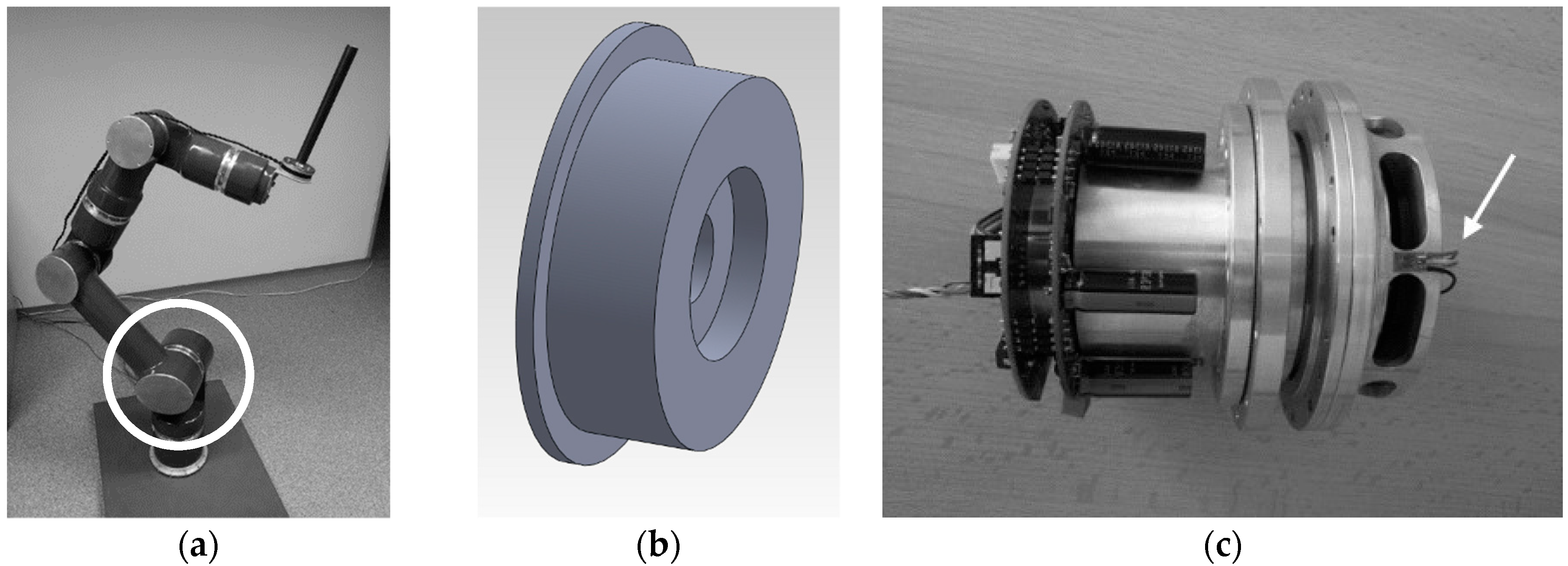
The aim of the proposed methodology of experimental measurement using strain gauge method is online monitoring of the prototype manipulator under operating load, which would allow not only validation of numerical calculations but also verification of repeatability of processes, assessment of the influence of the number of load cycles on the stress state at critical nodes. For the experimental validation of the methodology, a flange was chosen, which is one of the load-bearing parts of the pivot joint transmitting the torque from the actuators (Figure 1a, white circle). Figure 1b shows the original structural design of the flange, and Figure 1c shows the flange with the proposed structural modifications. The proposed modification increased the stress levels on the outer surface of the flange to a measurable level and, at the same time, provided the required stiffness.

Figure 1.
Prototype of the manipulator with an indication of the place to be analysed. (a) General view; (b) original shape of the flange; (c) flange with design modification as part of the pivot joint.
The determination of the torque using strain gauge method is directly proportional to the measured value of the strain in the elastic deformation region. However, the implementation of the experimental measurement requires the assurance of several requirements. One of the essential ones is the selection of a suitable measurement location, where it is necessary to take into account the dimensions of the strain gauges, their wiring, the transmission of the measured signal to the measuring apparatus and, above all, to ensure sufficient measurement sensitivity in terms of correct evaluation of the measured data. The location of the strain gauges was chosen on the outer surface of the flange (see Figure 1c, white arrow). An initial stress–strain analysis was carried out using the finite element method. As mentioned in the introduction, many researchers have developed their custom sensors, either force or torque, using numerical modelling. However, these are often new mechanical parts that need to be embedded between other mechanical parts of the manipulator [21]. In this paper, the authors describe a procedure where a low-cost torque sensor is obtained by designing a modification to an existing part of the manipulator, namely, a flange. For the original design of the flange (Figure 1b), low-stress levels were determined on the external circumference of the flange, which, on the one hand, can be considered satisfactory in terms of stiffness; on the other hand, the results obtained experimentally would be challenging to analyse in this case (low sensitivity/significant measurement error). For this reason, structural modification of the flange was proposed so that the stiffness would meet the required parameters, and at the same time, the stress levels would be increased at pre-selected locations to the required level in terms of the applicability of the strain gauge measurement (Figure 1c). The last step was the experimental validation of the proposed methodology on physical models.
2.1. Stress/Strain Analysis of the Load-Bearing Manipulator Link Element
Numerical stress/strain analysis was performed for the original and modified shape of the load-bearing manipulator element (flange) used to transfer the force flow (driving effect) between the individual link members. The flange material is ENAW 5054 with a yield stress of 115 MPa, an ultimate tensile strength of 250 MPa and a shear modulus of G = 26,900 MPa. The required torque range under operating load is from 28 Nm to 200 Nm. The determination of the maximum stresses was carried out under static loading in the linear deformation region. Based on the values of the equivalent von Mises stresses, σMises, the values of the maximum shear stress, τ, can be determined for the components subjected to torsion according to the relation [22]:
Using the following relationship:
where τ is the shear stress, ε45 is the principal strain and G is the shear modulus. Value of the strain determined analytically will be compared with the values obtained by strain gauge method.
τ = 2ε45·G
2.2. Experimental Measurement
The experimental measurement was divided into two parts. In the first one, static loads were considered to verify the results obtained by numerical modelling using the finite element method. In the second part, the dynamic effects that can occur when the individual links of the manipulator accelerate or decelerate, or as a result of the vibration of the transferred object, were investigated.
Part one: The strain gauge method was chosen for the experimental measurement. In order to consider the measured values as relevant and able to validate the results obtained by numerical modelling, it was necessary to design a loading mechanism to allow calibration measurements to be carried out. Figure 2 shows a test stand where the loading torque was induced by force acting on a known lever arm. The magnitude of the force was registered by a calibrated RSCC force sensor (HBM, Darmstadt, Germany). Radial bearings were used to eliminate the bending effect. A highly dynamic universal amplifier Quantum MX410 combined with the evaluation software CatmanEasy 3.5.1.48 (HBM, Darmstadt, Germany) was used to measure the analysed data. The available sampling frequency range is from 1 Hz to 19,200 Hz; thus, it is also suitable for dynamic measurements.
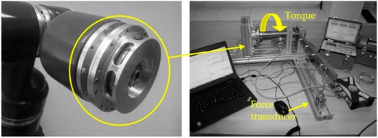
Figure 2.
View of the torque measurement carried out on the flange that is part of the pivot joint.
The purpose of the experimental measurements was to verify the suitability of the flange design modification to increase the sensitivity of the measured data while ensuring the required stiffness. For the values of the strains, εa, registered by the strain gauge apparatus when the strain gauges are connected to the half-bridge, the following applies: εa = 2ε45. Based on the evaluation of the increments in the measured values from the operating load, it can be concluded that the strain/stress states correspond to the results of the numerical modelling.
Part two: The second part of the experimental measurements was focused on the case when the manipulator link may oscillate when handling the load. The above case was simulated by the vibration of a beam with a load attached to a rigid arm, as shown in Figure 3. Since a Quantum MX410 also allows the connection of acceleration sensors, the authors also carried out measurements using two uniaxial accelerometers, type Bruel & Kjaer 4507B. The accelerometers were installed on the beam at location A1 and on the flange at location A2, as shown in Figure 3. The measurements aimed to compare the amplitude spectra obtained from the samples recorded by the accelerometers and strain gauges.
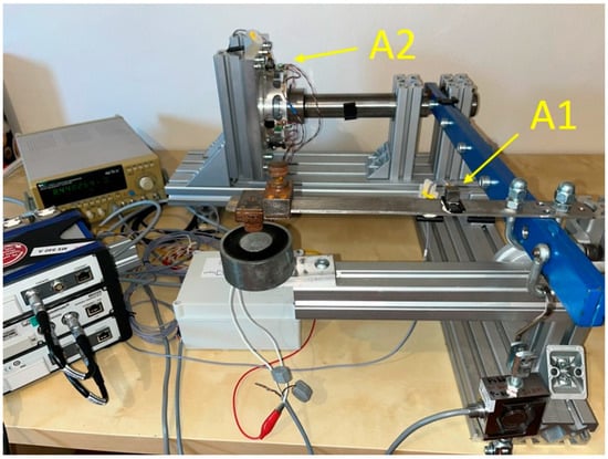
Figure 3.
Measuring stand for the realization of dynamic analysis.
The experimental measurements show that the proposed methodology using the strain gauge method is so sensitive that even at low amplitudes of the measured strains and with a suitable sampling frequency, it allows estimating the natural frequencies of the assembled mechanical system, taking into account its real couplings. Measurements carried out on the flange already under laboratory conditions confirmed that they take into account not only manufacturing and assembly inaccuracies but also the accuracy of applying strain gauge sensors at the selected location.
3. Results
3.1. Numerical Analysis Using FEM
Several design modifications were analysed by numerical modelling using the finite element method in terms of the shape of the hole, its size and the number of holes. In the present paper, the most advantageous variant of the design modification of the existing component is presented, which decreased the overall mass of the manipulator and did not require any design modifications to other components.
When defining the boundary conditions, it was taken into account that the considered flange is loaded only by torque. SolidWorks 2018 software was used for the numerical analysis. The finite element model without structural modifications was composed of 16,674 nodes and 8311 volume elements with quadratic approximation. The finite element model with structural modifications was composed of 260,099 nodes and 157,783 volume elements with quadratic approximation.
Figure 4 and Figure 5 show the equivalent (von Mises) stress field and the displacement field for the original and modified shape of the flange under consideration at a maximum load of 200 Nm. From the figures, it is clear that the above design modification increased the stress levels around the concentrators, i.e., in the areas between the oval holes chosen as the application locations of the strain gauge sensors.
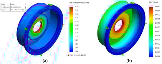
Figure 4.
Fields obtained using maximum torque of 200 Nm for the original shape of the flange. (a) Equivalent (von Mises) stress; (b) total displacement.

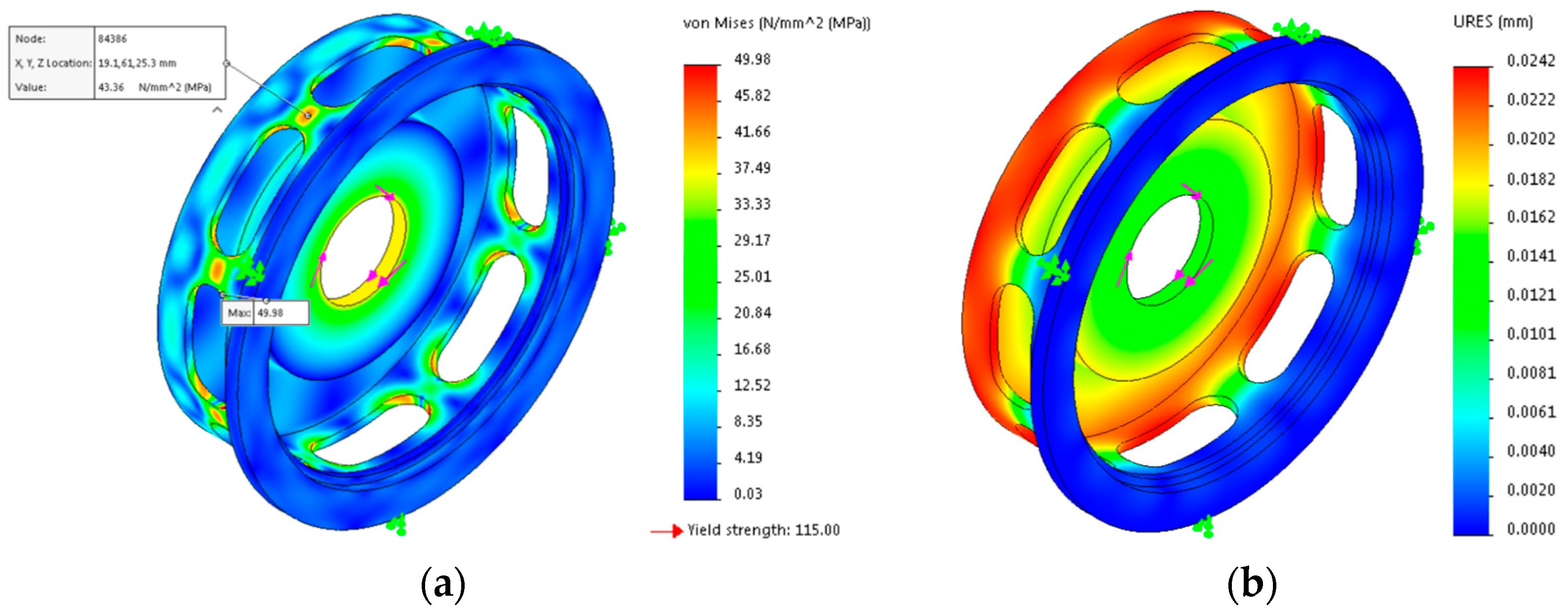
Figure 5.
Fields obtained using maximum torque of 200 Nm for the modified shape of the flange. (a) Equivalent (von Mises) stress; (b) total displacement.
As already mentioned, the presented methodology is based on comparing the principal strains registered by the strain gauge at the location of its application. In Figure 6, for illustration, the values of the principal strains at a maximum torque load of 200 Nm are presented. At the location of the applied strain gauge, the principal strains were numerically computed as ε1 = 446 με and ε3 = −452 με.
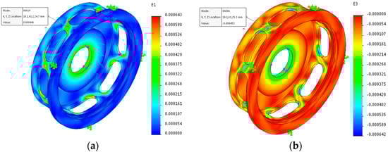
Figure 6.
Fields of principal strains obtained using maximum torque of 200 Nm for the modified shape of the flange. (a) ε1; (b) ε3.
Table 1 shows the results of the above numerical FEA corresponding to the minimum (28 Nm) and maximum (200 Nm) operational loads of the flange with structural modification.

Table 1.
Values of equivalent and shear stresses, strains and maximum total displacements for the flange under consideration at the minimum and maximum operating loads.
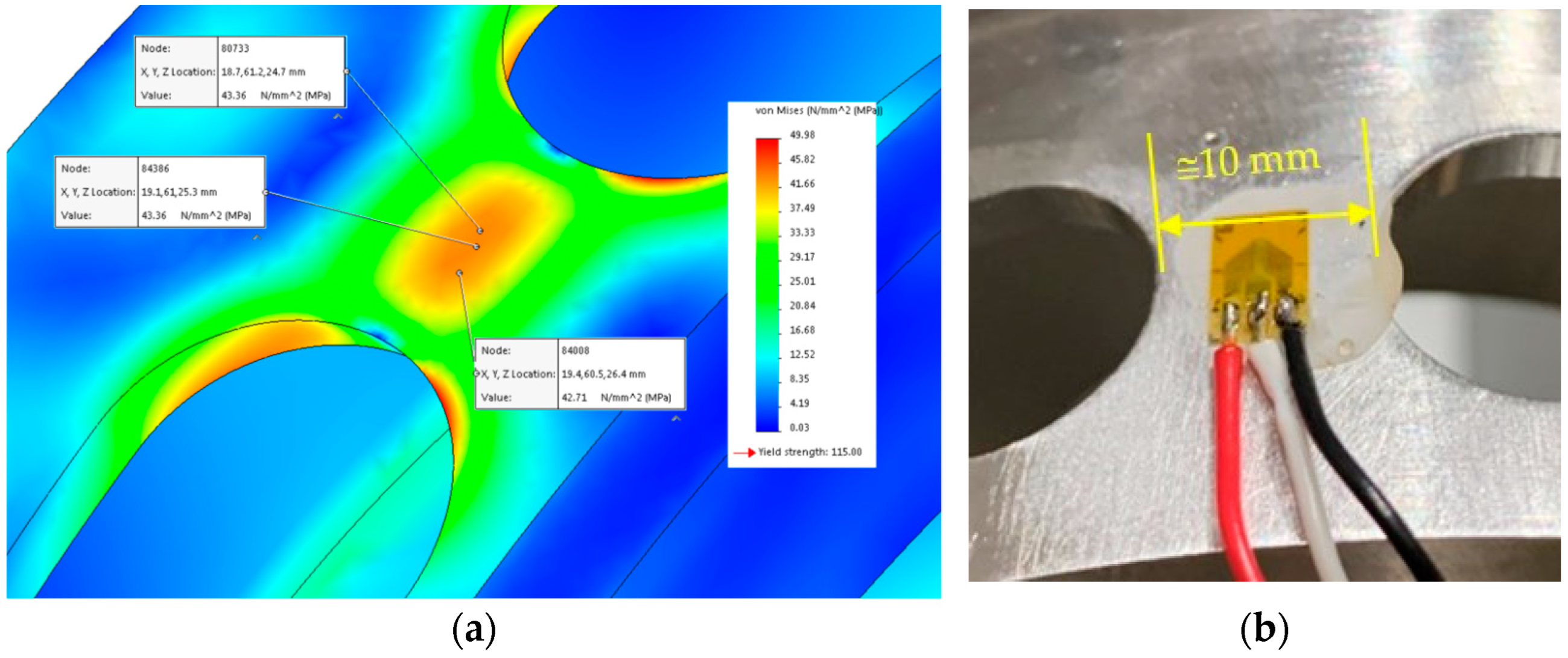
Figure 7a shows the equivalent (von Mises) stress field obtained at the location of the applied strain gauge. It is obvious that the values of the equivalent stresses (about 43 MPa) can be considered constant in the area of the strain gauge measuring grids.

Figure 7.
Location of the applied strain gauge. (a) Field of equivalent (von Mises) stress, (b) strain gauge XY41/3-120.
The following section presents the procedure for validating numerical modelling results by experimental measurements using the strain gauge method.
3.2. Experimental Measurement
The strain gauges’ dimensions were considered in the design of the modified flange shape. Strain gauges with two measuring grids are most commonly used to measure torsionally stressed members. Four strain gauges XY41/3-120 (HBM, Darmstadt, Germany) were used (Figure 7b), spaced evenly around the circumference of the analysed flange. The half-bridge was used for wiring the measuring grids to exclude tension and bending.
3.2.1. STAGE 1 Verification of Measurement Repeatability—Static Measurement
The first step was a calibration measurement under static loading to verify the correct functionality of the applied strain gauges. The torque was induced by force applied on the rigid arm at a perpendicular distance of 500 mm from the flange axis (see Figure 2). The force sensor registered the magnitude of the loading force. The sampling frequency was set to 200 Hz.
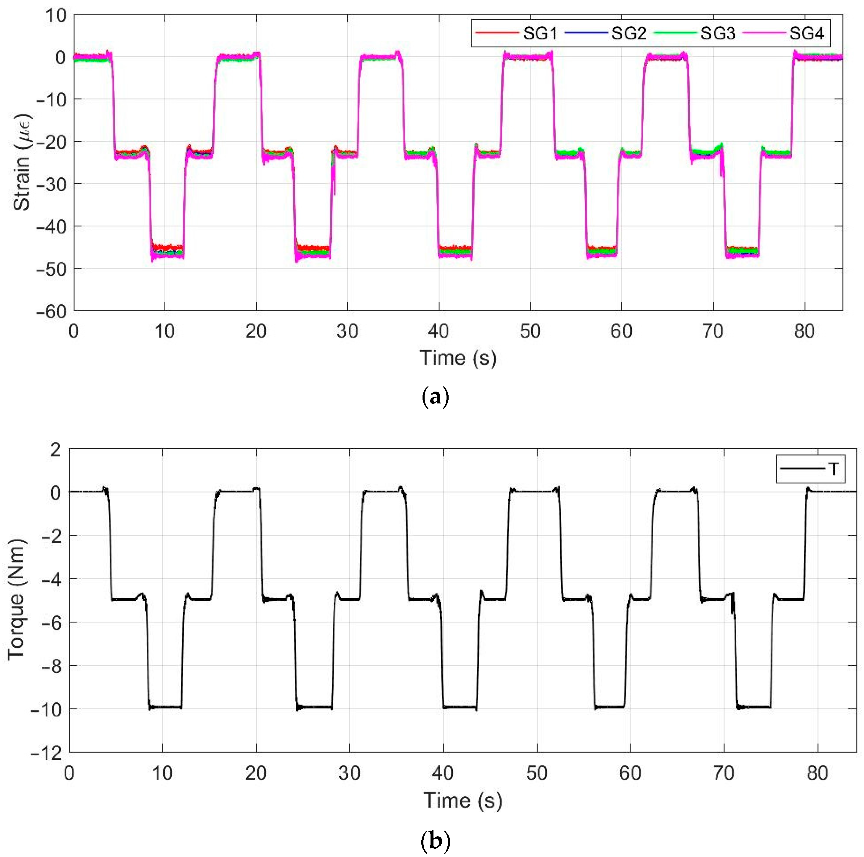
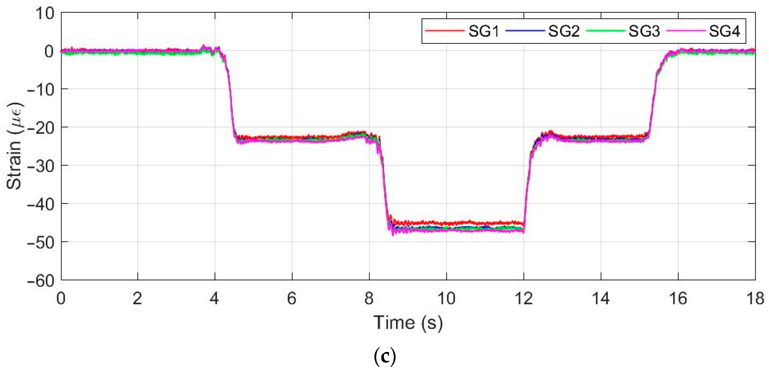
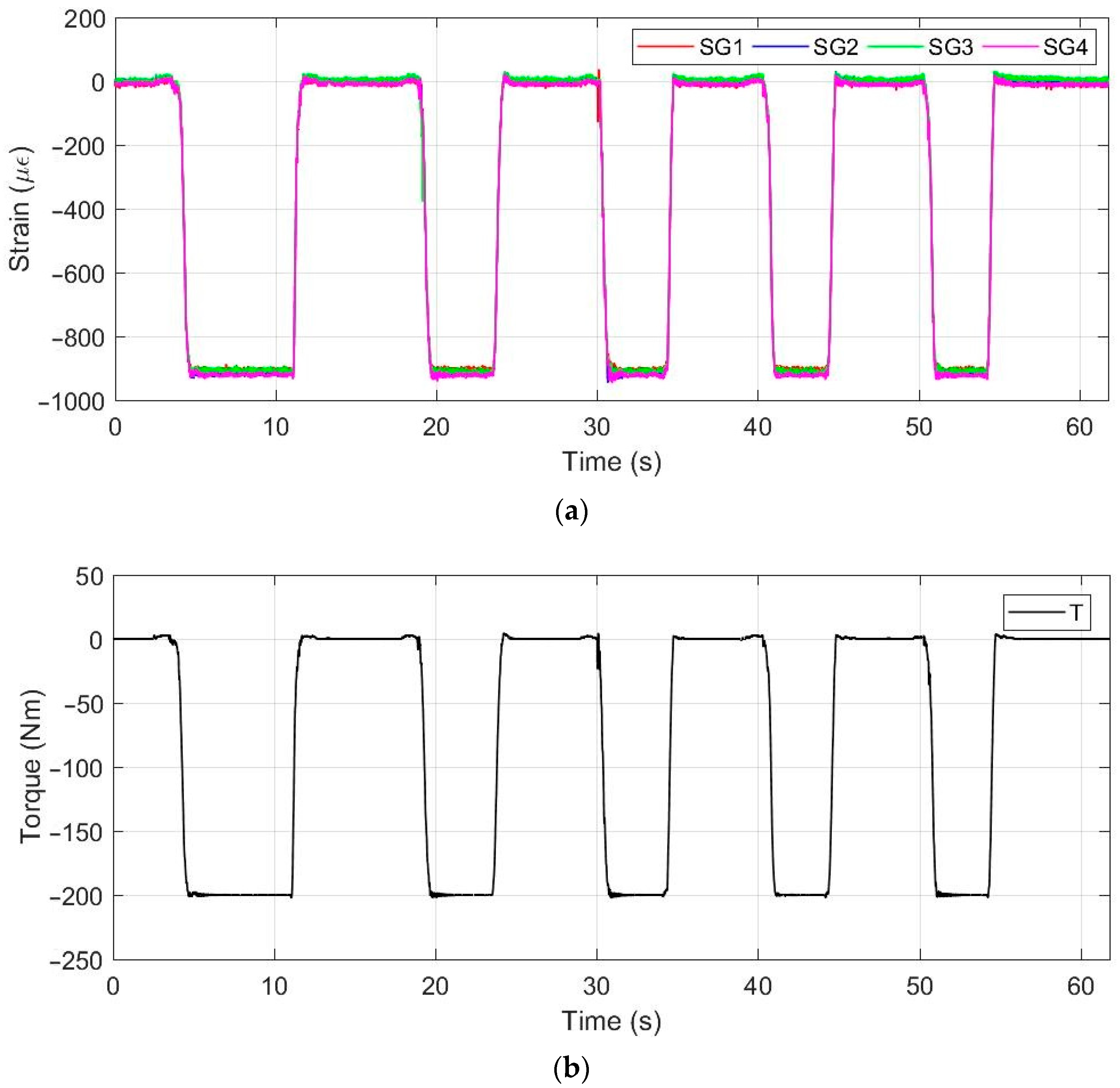
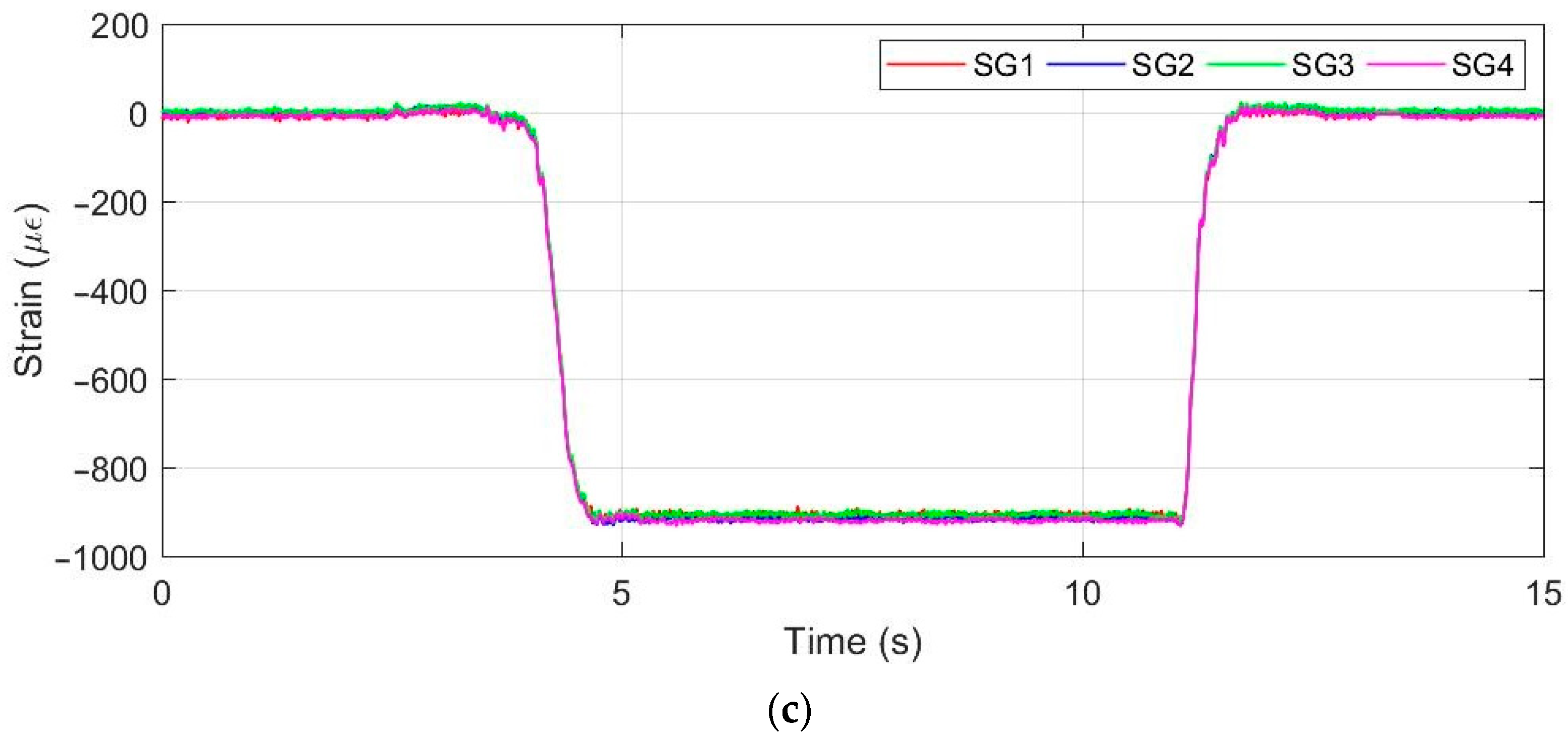
Figure 8 shows an example of the time records of the strains registered by four strain gauges. The flange was loaded in two steps with torques of 5 Nm and 10 Nm and then unloaded. The above procedure was repeated five times within one measurement. The aim was to determine the sensitivity of the measurement at low load levels. It should be noted that the considered flange is designed for a minimum operating torque of 28 Nm. In Figure 9, the time records of the strains over the entire working range, i.e., up to a torque value of 200 Nm, are documented.
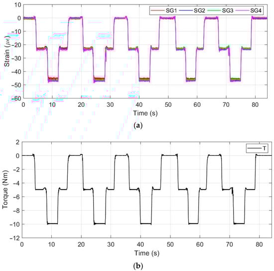
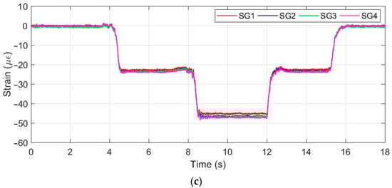
Figure 8.
(a) Time record of the strains registered by the strain gauges at 5 Nm and 10 Nm load; (b) time record of the torque; (c) the time record detail of the strains for one cycle.
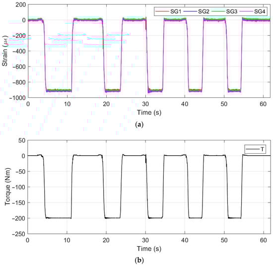
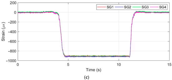
Figure 9.
(a) Time record of the strains registered by the strain gauges at a maximum 200 Nm load; (b) time record of the torque; (c) the time record detail of the strains for one cycle.
Table 2 shows the mean values and standard deviations of the strains registered separately for each of the five loading cycles at different torque levels (5 Nm, 10 Nm and 200 Nm).
Table 2.
Mean values and standard deviations of the strains registered separately for each of the five loading cycles.
Table 2 shows that the measured values achieved excellent agreement at low and also high load levels. According to the HBM manufacturer (Germany), with a measured value of less than 1500, the measurement error per million cycles is less than 10 [23]. For this reason, the measurement error under cyclic loading, even at the maximum load (200 Nm), will not exceed 1%.
Table 3 compares the values of shear stresses obtained by numerical modelling and experimental measurements using Relations (1) and (2) at two load levels. The measured values are averaged from five measurements for each of the four strain gauges (see Table 2).
Table 3.
Values of shear stresses obtained by numerical modelling and experimental measurements.
3.2.2. STAGE 2 Dynamic Measurement
As a Quantum MX410 is compatible with various measurement sensors, two accelerometers were added to the measurement chain as part of the second stage. The aim was to assess the vibrations transmitted to the flange caused by the vibration of the beam attached to the rigid arm and to verify the possibilities of using the applied strain gauges in the analysis of the manipulator vibration. A first uniaxial acceleration sensor type 4507B (Bruel & Kjaer) was installed on the flange at location A2, and a second uniaxial sensor type 4507B was placed on the beam at location A1 (see Figure 3).
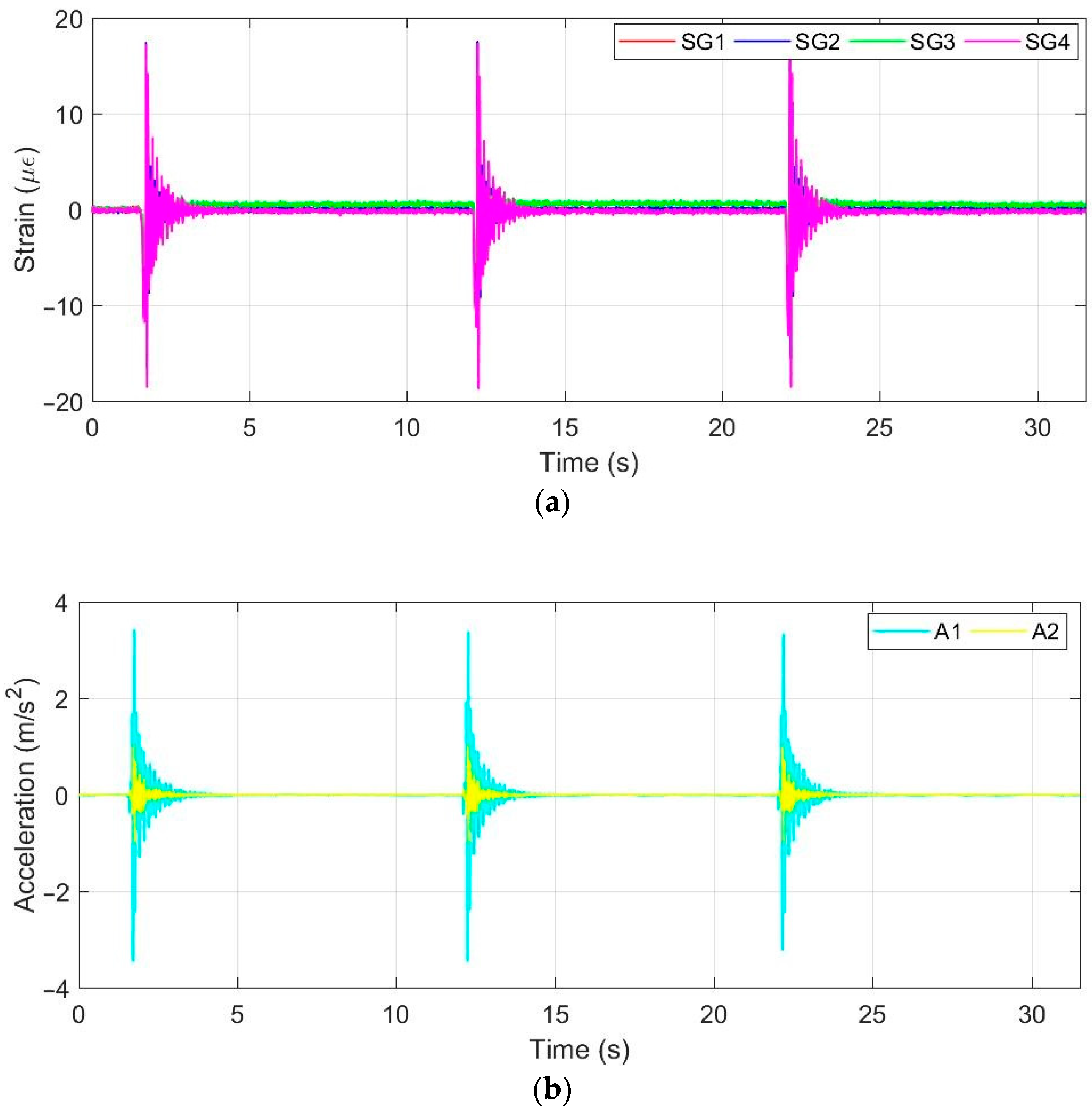
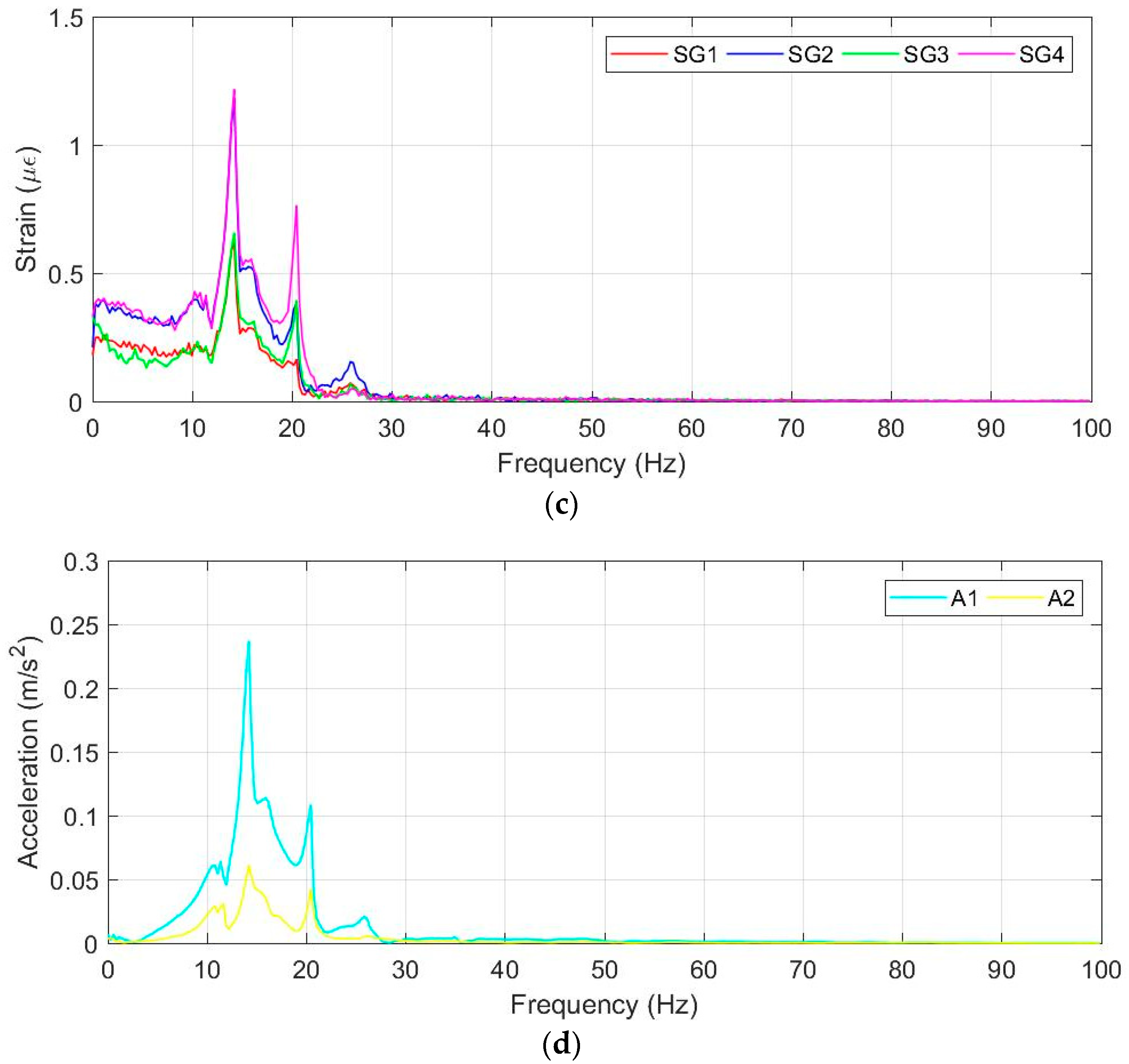
The measurement of the free vibration of the beam was carried out first. In Figure 10a,b, the time records of the strains and accelerations during the free vibration of the beam attached to the rigid arm are documented. The measurement was repeated three times. Figure 10c,d show the amplitude spectra corresponding to the first vibration cycle depicted in Figure 10a,b.
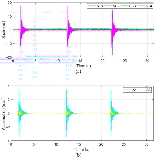
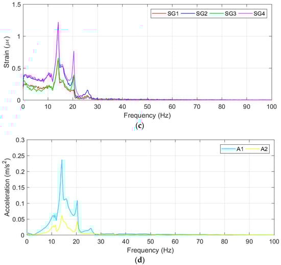
Figure 10.
Free vibration of the beam attached to the rigid arm. (a) Time record of measured strains; (b) time record of accelerations; (c) amplitude spectrum of strains; (d) amplitude spectrum of accelerations.
From Figure 10c,d, it is obvious that both strain gauges and accelerometers identified the same values of the natural frequencies of the analysed mechanical system.
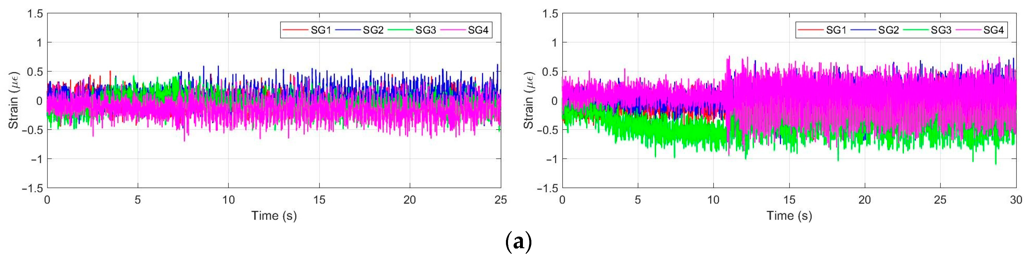
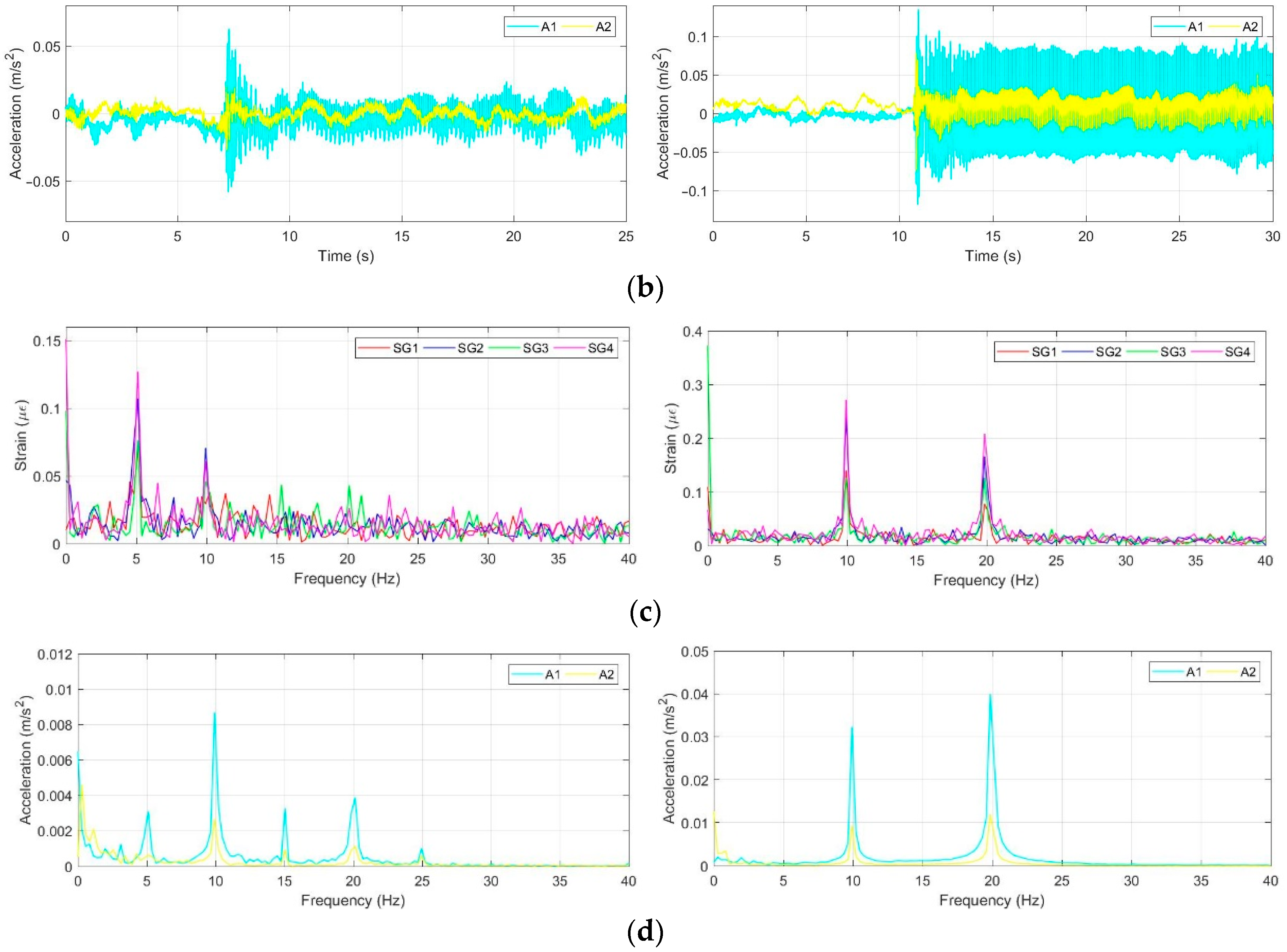
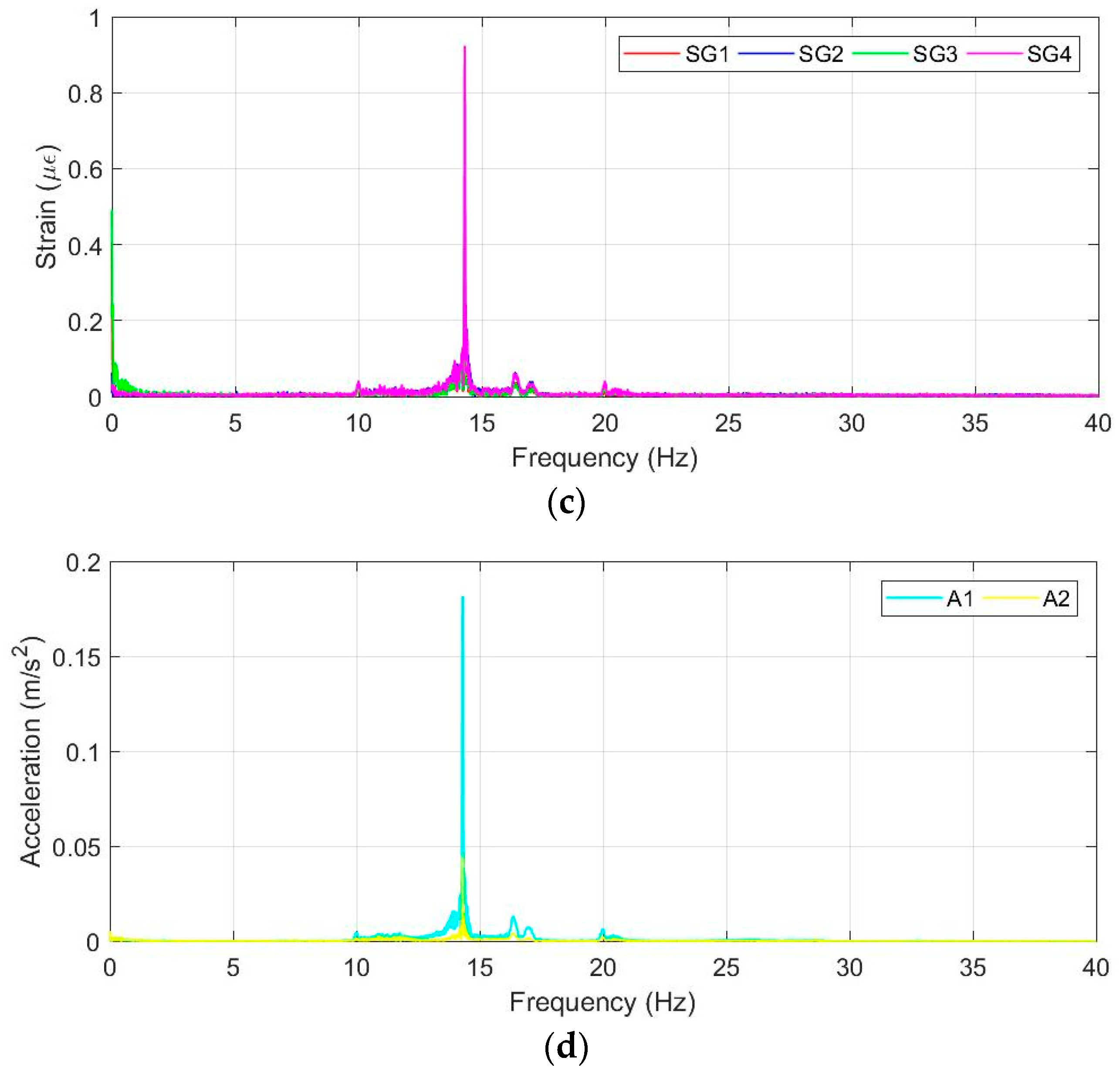
The measurement of the forced vibration of the beam at a known frequency using an MXG 9802 signal generator was carried out as the second one. Three regimes were simulated: forced vibration at 5 Hz (Figure 11 left) and 10 Hz (Figure 11 right) and measurements at varying excitation frequencies (Figure 12). For the evaluations of amplitude spectra in the first two regimes, the time intervals between 11–14.5 s (for 5 Hz) and 15–17.5 s (for 10 Hz) were chosen. The amplitude spectrum of the third regime was obtained using all of the samples registered during excitation.

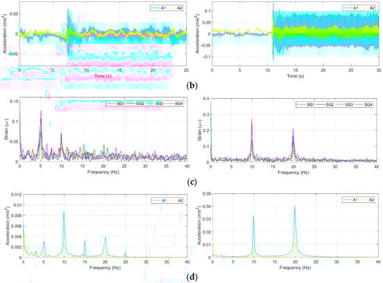
Figure 11.
Forced vibrations at 5 Hz (left) and 10 Hz (right). (a) Time record of strains registered by strain gauges; (b) time record of accelerations registered by accelerometers; (c) amplitude spectrum of strains; (d) amplitude spectrum of accelerations.
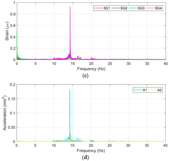
Figure 12.
Forced vibrations at low frequencies. (a) Time record of strains registered by strain gauges; (b) time record of accelerations registered by accelerometers; (c) amplitude spectrum of strains; (d) amplitude spectrum of accelerations.
4. Discussion
The present methodology investigated the innovative use of the strain gauge method in combination with a structural modification of a manipulator link load-bearing element. The advantage of the proposed low-cost torque sensor using the strain gauge method is the possibility to register and evaluate the dynamic effects (vibrations) of the whole mechanical system during real operating conditions as well as their influence on the stresses in selected structural elements in case of setting a higher sampling frequency. Based on the deformation and stress analysis carried out in real operating regimes on a physical model, it is possible to verify the results obtained by numerical modelling on computational models and, thus, to verify the correctness of the boundary conditions used. The advantage of the presented methodology is the possibility to analyse the stress states depending on the parameter settings of the drive units. The force effects acting on the manipulator link can also be measured when it is braked.
Based on a series of experimental measurements under static and dynamic loading and the results obtained by numerical modelling, the following can be stated:
- Strain gauge measurements on the modified flange under static loading confirmed perfect agreement (less than 2%) with the numerical modelling results over the entire working range (28 Nm to 200 Nm).
- The measurements under dynamic loading were analysed by comparing the amplitude spectra obtained from time records of the strains and accelerations. The amplitude spectra documented perfect agreement between strain gauges and accelerometers, which can be used in practice for vibration analysis. The strain gauge measurements documented excellent agreement in the frequency domain compared to the accelerometers, even at low strain levels of the order of microstrain units (Figure 11a).
- Strain gauges provide information on the mechanical stress history, which can be used to investigate the influence of the number of cycling loads on positioning accuracy.
- The design of a low-cost torque sensor represents a simple solution to measure torque using a modified flange without intervention in other parts of the manipulator.
The proposed methodology is mainly suitable for testing newly designed (prototype) manipulators. The use in long-term operation, for which the manipulators are designed (repeatability of operations), is possible by replacing the flanges with strain gauges as part of planned maintenance.
Author Contributions
Conceptualization, M.P.; methodology, M.P. and M.H.; validation, M.P., M.H. and Š.G.; formal analysis, M.S. and Š.G.; investigation, M.P., M.H. and Š.G.; resources, M.S.; data curation, M.P. and M.H.; writing—original draft preparation, M.P. and M.H.; visualization, Š.G.; supervision, M.P.; project administration, M.H.; funding acquisition, M.P. and Š.G. All authors have read and agreed to the published version of the manuscript.
Funding
This work was supported by the following projects: VEGA 1/0516/22, VEGA 1/0509/23 and KEGA 011ZU-4/2022.
Institutional Review Board Statement
Not applicable.
Informed Consent Statement
Not applicable.
Data Availability Statement
The data that support the findings of this study are available from the corresponding author upon request.
Conflicts of Interest
The authors declare no conflict of interest.
References
- Vysocky, A.; Novak, P. Human-robot collaboration in industry. MM Sci. J. 2016, 9, 903–906. [Google Scholar] [CrossRef]
- Villani, V.; Pini, F.; Leali, F.; Secchi, C. Survey on human–robot collaboration in industrial settings: Safety, intuitive interfaces and applications. Mechatronics 2018, 55, 248–266. [Google Scholar] [CrossRef]
- Wang, L.; Gao, R.; Váncza, J.; Krüger, J.; Wang, X.V.; Makris, S.; Chryssolouris, G. Symbiotic Human-robot collaborative assembly. CIRP Ann. 2019, 68, 701–726. [Google Scholar] [CrossRef]
- Wang, L. Collaborative robot monitoring and control for enhanced sustainability. Int. J. Adv. Manuf. Technol. 2015, 81, 1433–1445. [Google Scholar] [CrossRef]
- Schneider, U.; Olofsson, B.; Sörnmo, O.; Drust, M.; Robertsson, A.; Hägele, M.; Johansson, R. Integrated approach to robotic machining with macro/micro-actuation. Robot. Comput.-Integr. Manuf. 2014, 30, 636–647. [Google Scholar] [CrossRef]
- Du, G.; Zhang, P.; Li, D. Online robot calibration based on hybrid sensors using Kalman Filters. Robot. Comput.-Integr. Manuf. 2015, 31, 91–100. [Google Scholar] [CrossRef]
- Bonci, A.; Cen Cheng, P.D.; Indri, M.; Nabissi, G.; Sibona, F. Human-robot perception in industrial environments: A survey. Sensors 2021, 21, 1571. [Google Scholar] [CrossRef]
- Lasota, P.; Shah, J. Analyzing the effects of human-aware motion planning on close-proximity human-robot collaboration. Hum. Factors J. Hum. Factors Ergon. Soc. 2015, 57, 21–33. [Google Scholar] [CrossRef] [PubMed]
- Hietanen, A.; Pieters, R.; Lanz, M.; Latokartano, J.; Kämäräinen, J.-K. AR-based interaction for human-robot collaborative manufacturing. Robot. Comput. Integr. Manuf. 2020, 63, 101891. [Google Scholar] [CrossRef]
- Scimmi, L.S.; Melchiorre, M.; Troise, M.; Mauro, S.; Pastorelli, S. A practical and effective layout for a safe human-robot collaborative assembly task. Appl. Sci. 2021, 11, 1763. [Google Scholar] [CrossRef]
- Grushko, S.; Vysocký, A.; Oščádal, P.; Vocetka, M.; Novák, P.; Bobovský, Z. Improved Mutual Understanding for Human-Robot Collaboration: Combining Human-Aware Motion Planning with Haptic Feedback Devices for Communicating Planned Trajectory. Sensors 2021, 21, 3673. [Google Scholar] [CrossRef] [PubMed]
- Kouritem, S.A.; Abouheaf, M.I.; Nahas, N.; Hassan, M. A multi-objective optimization design of industrial robot arms. Alex. Eng. J. 2022, 61, 12847–12867. [Google Scholar] [CrossRef]
- Kovincic, N.; Mueller, A.; Gattringer, H.; Weyrer, M.; Schlotzhauer, A.; Brandstötter, M. Dynamic parameter identification of the Universal Robots UR5. In Proceedings of the Austrian Robotics Workshop 2019, Steyr, Austria, 9–10 May 2019. [Google Scholar]
- Kot, T.; Bobovský, Z.; Vysocký, A.; Krys, V.; Šafařík, J.; Ružarovský, R. Method for Robot Manipulator Joint Wear Reduction by Finding the Optimal Robot Placement in a Robotic Cell. Appl. Sci. 2021, 11, 5398. [Google Scholar] [CrossRef]
- Unhelkar, V.V.; Lasota, P.A.; Tyroller, Q.; Buhai, R.-D.; Marceau, L.; Deml, B.; Shah, J.A. Human-aware robotic assistant for collaborative assembly: Integrating human motion prediction with planning in time. IEEE Robot. Autom. Lett. 2018, 3, 2394–2401. [Google Scholar] [CrossRef]
- Park, J.J.; Haddadin, S.; Song, J.-B.; Albu-Schäffer, A. Designing optimally safe robot surface properties for minimizing the stress characteristics of Human-Robot collisions. IEEE ICRA 2011, 5980282, 5413–5420. [Google Scholar]
- Diaz, J.R.; Mukherjee, P.; Verl, A. Automatic Close-optimal Workpiece Positioning for Robotic Manufacturing. Procedia CIRP 2018, 72, 277–284. [Google Scholar] [CrossRef]
- Albu-Schäffer, A.; Haddadin, S.; Ott, C.; Stemmer, A.; Wimböck, T.; Hirzinger, G. The DLR lightweight robot: Design and control concepts for robots in human environments. Ind. Robot. 2007, 34, 376–385. [Google Scholar] [CrossRef]
- Hirzinger, G.; Sporer, N.; Schedl, M.; Butterfaß, J.; Grebenstein, M. Torque-Controlled Lightweight Arms and Articulated Hands: Do We Reach Technological Limits Now? Int. J. Robot. Res. 2004, 23, 331–340. [Google Scholar] [CrossRef]
- Billeschou, P.; Albertsen, C.; Larsen, J.C.; Manoonpong, P. A Low-Cost, Compact, Sealed, Three-Axis Force/Torque Sensor for Walking Robots. IEEE Sens. J. 2021, 21, 8916–8926. [Google Scholar] [CrossRef]
- Ubeda, R.P.; Rubert, S.C.G.; Stanisic, R.Z.; Ivars, Á.P. Design and Manufacturing of an Ultra-Low-Cost Custom Torque Sensor for Robotics. Sensors 2018, 18, 1786. [Google Scholar] [CrossRef] [PubMed]
- Trebuňa, F.; Šimčák, F. Príručka Experimentálnej Mechaniky, 1st ed.; Typopress: Košice, Slovakia, 2007; pp. 445–460. [Google Scholar]
- HBM Strain Gauges—First Choice for Strain Measurements. Available online: https://www.hbm.com/fileadmin/mediapool/hbmdoc/technical/S01265.pdf (accessed on 2 May 2023).


Disclaimer/Publisher’s Note: The statements, opinions and data contained in all publications are solely those of the individual author(s) and contributor(s) and not of MDPI and/or the editor(s). MDPI and/or the editor(s) disclaim responsibility for any injury to people or property resulting from any ideas, methods, instructions or products referred to in the content. |
© 2023 by the authors. Licensee MDPI, Basel, Switzerland. This article is an open access article distributed under the terms and conditions of the Creative Commons Attribution (CC BY) license (https://creativecommons.org/licenses/by/4.0/).