Review

Smart Materials for Green(er) Cities, a Short Review

1
Carinthia Institute for Smart Materials (CiSMAT), Carinthia University of Applied Sciences, 9524 Villach, Austria
2
Polymer Competence Center Leoben (PCCL), 8700 Leoben, Austria
3
Material-Technology Innsbruck (MTI), University of Innsbruck, 6020 Innsbruck, Austria
*
Author to whom correspondence should be addressed.
Appl. Sci. 2023, 13(16), 9289; https://doi.org/10.3390/app13169289
Submission received: 25 July 2023 / Revised: 11 August 2023 / Accepted: 14 August 2023 / Published: 16 August 2023
(This article belongs to the Special Issue Smart Materials for a Green(er) Economy)

Abstract

:
The transition to sustainable or green(er) cities requires the development and implementation of many innovative technologies. It is vital to ensure that these technologies are themselves as sustainable and green as possible. In this context, smart materials offer excellent prospects for application. They are capable of performing a number of tasks (e.g., repair, opening/closing, temperature measurement, storage and release of thermal energy) without embedded electronics or power supplies. In this short review paper, we present some of the most promising smart material-based technologies for sustainable or green(er) cities. We will briefly present the state-of-the-art in smart concrete for the structural health monitoring and self-healing of civil engineering structures, phase-change materials (PCM) for passive air-conditioning, shape-memory materials (SMA) for various green applications, and meta-surfaces for green acoustics. To better illustrate the potential of some of the solutions discussed in the paper, we present, where appropriate, our most recent experimental results (e.g., embedded SAW sensors for the Structural Health Monitoring of concrete structures). The main aim of this paper is to promote green solutions based on smart materials to engineers and scientists involved in R&D projects for green(er) cities.

1. Introduction

Over and above the environmental problems that the use of fossil fuels poses or may pose, the probable depletion of these same resources in the following decades is prompting us to rethink the infrastructure of our cities so as to drastically reduce their need for fossil fuels. The classic way to achieve this is to replace fossil fuels with renewable energy. However, it will be very difficult to completely replace fossil fuels with renewable energies in the short or even medium term [1]. It is therefore important to find solutions to reduce the overall energy consumption of our cities.
The most popular route to smarter, energy-efficient cities is the Smart City. Here, the latest Internet-of-Things technologies are used on a massive scale to acquire as much Data as possible and then use it to optimize, among other parameters, energy consumption [2,3,4]. However, this approach has a number of disadvantages, not least the need to manufacture and integrate millions of tiny electronic circuits into everyday objects and surrounding structures, then interrogate these communicating objects and store and process the data. These operations consume a lot of energy. The presence of electronics in everyday objects also poses obvious recycling problems. The disadvantages of using IoT-type technologies can therefore quickly outweigh the benefits when it comes to making cities greener [5].
To make cities both smarter and more energy efficient, we believe we also need to explore other possible families of solutions. One of these is based on the use of intelligent materials, capable of reacting on their own to external stimuli or performing useful tasks without the need for electronics or on-board energy. “Green Tech” solutions based on these materials are, in the vast majority of cases, simpler to manufacture, implement and recycle than their conventional counterparts based on embedded electronics and/or mechatronic automation.
In the following short review paper, we will focus on a number of smart materials whose applications we believe could make a significant contribution to reducing the energy consumption of cities, while at the same time making them smarter. Our review is by no means exhaustive. Rather, our aim is to highlight, through some examples, the potential of smart materials (as a whole) for greener cities.
Several classes of smart materials can be used to make cities smarter and more energy-efficient. These include phase-change materials (PCM), shape-memory alloys (SMA) and self-healing materials. Here, we use the intrinsic physicochemical properties of materials and their ability to react to external stimuli (e.g., increased temperature, increased sunlight, appearance of a crack) to ultimately reduce the environmental impact of the structures of which they are an integral part. In this paper, we will also look at how metamaterials, and more specifically meta-surfaces, can be used to make buildings greener. We will also study one example of a classical material made “smarter” and greener by the integration of sensors, namely “smart concrete”. In our case, the integrated sensors are themselves fully passive and wireless, with no embedded electronics of battery. This gives this solution a number of advantages over existing solutions. We will notably discuss possible applications of the aforementioned smart materials for passive air-conditioning applications, green acoustic insulation, and product life-span extension. Where appropriate, we will provide new experimental results obtained as part of our own research projects.

2. Smart Materials for Green(er) Cities

2.1. Self-Healing Concrete

Introducing autonomous repairability and healability in cementitious materials represents an innovative strategy to extend the lifetime and reduce the CO2 footprint of buildings [6,7,8,9]. To date, concrete is the most widely applied material in the construction industry owing to its high mechanical properties paired with low production costs [10]. Concrete is formed by mixing cement, water, sand and coarse fillers. Subsequently, the cementitious phase is dried and cured, yielding calcium–silicate–hydrate (C–S–H) domains, which mainly contribute to the stiffness of the inorganic composite. While concrete benefits from a high compressive strength, its tensile properties (tensile strength and elongation) are limited [11]. Thus, concrete used for the construction of bridges, roads or buildings is prone to cracking during the lifetime of these structures [12]. Equipping concrete with a self-healing function is one way to ensure the structural integrity of buildings without costly and time-consuming maintenance and repair, as the material is able to close the damage zone without external intervention [13]. Here, it should be noted that cementitious materials—without a particular modification—can autonomously heal cracks, albeit at a limited crack size (<50 µm) [14]. This so-called autogenous healing can be based on various mechanisms: (i) a delayed hydration of residual cement reagents [15], (ii) the carbonation of dissolved calcium hydroxide [16], (iii) a swelling of the C–S–H phases [17] or (iv) the physical closure of cracks by small particles present in water [18]. However, in all cases, water is required to come in contact with the damage zone and to react with the concrete matrix or to transport the required reagents.
Another route to deposit materials and to physically seal small cracks in concrete is the precipitation of calcium carbonate with the help of selected bacteria [19]. Various types of bacteria have been reported that are able to survive the highly alkaline environment of cementitious materials and form calcium carbonate via different metabolisms (e.g., aerobic respiration of dissolved inorganic carbon, urea hydrolysis or nitrate reduction) [20]. While some bacterial spores can be directly mixed with cementitious materials, the majority of the reported concepts use carriers such as clay or activated carbon particles to extend the lifetime of the bacteria and protect them during the processing of concrete [21,22,23]. However, the limited lifetime of bacteria is only one issue when it comes to the industrial implementation of bacterial-based self-healable concrete. The bacteria also need optimum conditions to produce calcium carbonate via certain metabolic pathways. In particular, the availability of oxygen is vital for bacteria relying on aerobic respiration [24] and urea hydrolysis [25] to perform self-healing. In contrast, oxygen, which diffuses though microcapillaries in concrete, might become a problem for anaerobic bacteria [26]. In addition, some types of bacteria, such as Bacillus pseudofirmus, are reported to negatively affect the compressive and tensile strength of concrete [27]. In their review, Fernandez et al. summarized that the potential of this type of self-healing cementitious material is in specific applications. These are aboveground, having slow crack-opening displacement rates. Indeed, crack closure can take up to a few months in the case of larger fracture sizes [6].
The ability to withstand larger deformation and to reduce crack propagation in both autogenous and bacteria-based self-healing concretes can be significantly improved by adding selected fibers based on carbon [28], cellulose [29], thermoplastics [30] or glass [31]. In the presence of the fibers, crack propagation can be prevented by fiber bridging, which is a well-established way in fiber-reinforced composites to improve their fracture toughness [32]. By ensuring a narrower width of the crack, the fibers facilitate the autogenous self-healing process, which is often limited to smaller fracture sizes [8,33]. Combined with the higher tensile properties, this significantly reduces the probability of structures’ failures.
In order to accelerate the healing time and slow down crack propagation, the addition of encapsulated repair agents has become a well-established self-healing strategy for concrete [34]. The liquid repair agents are embedded in microcapsules, which should break during a damage event and release the agent into the damage zone. At the same time, the microcapsules have to be sufficiently strong to withstand the mixing process and to be homogenously distributed through the concrete matrix. This makes the synthesis and design of the microcapsules quite challenging. Encapsulation materials are typically based on polystyrene methyl methacrylate [35], urea-formaldehyde [36], phenol–formaldehyde [37], glass [38] or ceramics [39]. Along with the type of materials, the mechanical properties, permeability and crack resistance of the capsules are also adjusted by wall thickness and surface chemistry [40]. Once broken, the physical and chemical repair of the crack in the concrete is induced by a chemical reaction of the healing agent (e.g., polymerization, curing), which solidifies the liquid at room temperature. In a single capsule approach, only one type of repair agent is used, which starts to react with water or components of the mortar as soon as it is released. A prominent example is the curing of cyanoacrylate monomers, which undergo moisture-induced anionic polymerization [41]. The curing proceeds rapidly at room temperature and is accelerated by the alkaline concrete matrix. In its cured state, cyanoacrylate polymers form a strong bond with cementitious materials and are able to prevent the formation of new cracks during reloading. Along with curing, moisture was also used to induce a foaming reaction of encapsulated polyurethane prepolymers, which has been successfully applied to heal damage in concrete. Due to volume expansion, larger defects could be efficiently healed [38,42]. Other single capsule strategies include the encapsulation of bacteria for the precipitation of calcium carbonate [43] or the encapsulation of sodium silicate solutions, which yield calcium silicate hydrate (C-S-H) gels by the reaction with calcium hydroxide present in the concrete matrix [44]. In contrast, in a dual-capsule approach, the repair agents are encapsulated in two different microcapsules separately. For autonomous self-healing, both capsules have to be broken and to release the repair agents (e.g., epoxy resins and amine hardeners) [45]. The use of microcapsules provides a fast way to heal cracks within concrete without an additional external trigger (alongside the damage event). Thus, this healing mechanism is not limited to buildings aboveground but can also be applied in self-healing concrete for dams and underground structures. However, it has to be considered that multiple healing events at the same damage location are typically not possible, as the healing agent is irreversibly consumed during the healing process.
A repeated healing of concrete, even if the damage occurs at the same site, can be realized by using hollow microchannels instead of capsules [46]. The channels mimicking vascular systems are able to store a larger amount of the healing agent and to transport/release it at the damage zone [47]. While the same healing mechanism and healing agents can be used as in the microcapsule approach, a low viscosity of the healing agent is crucial to filling it in an interconnected hollow fiber network. For healing larger cracks, wires made from shape memory alloys (SMA) such as NiTinol (a nickel–titanium alloy, see also Section 2.3) were added to assist the physical closure of the crack, which was followed by chemical healing via the broken hollow channels [48]. The physical healing relied on the thermo-activated recovery of the original shape of the SMA wires and their super-elasticity allowed them to withstand large inelastic deformations and a recovery of the original shape once the external force was removed [49]. Thus, the healing mechanism is not fully autonomous, as heat (typical > 60 °C) is required to trigger the shape recovery process of the wires [50]. This limits the applicability to structures that are regularly subjected to higher temperatures (e.g., nuclear reactor structures, pavement, bridges, etc.) [51]. Although the additives significantly increase the costs of concrete, the combination of physical and chemical crack closure is highly efficient. It is reported that the related structures are able to recover from extremely large deformation arising during earthquakes.
A further strategy toward multiple self-healing of concrete at the same damage zone involves the addition of functional polymers to the cementitious mixture [52]. The healing with functional polymers is highly versatile and relies on various reversible mechanisms, such as (i) water-based swelling of superabsorbent polymers [53], (ii) thermo-activated change in viscosity (e.g., covalent adaptable polymer networks) [54] and (iii) thermo-activated expansion/contraction of shape-memory polymers (SMP) [55]. Along with the self-healing function, it has been reported that the employment of selected polymers positively influences fracture toughness, permeability and ductility of concrete [56].
Besides concrete, chemical (e.g., microcapsules, vascular systems or dynamic polymer networks) and physical (e.g., swelling) self-healing approaches have been developed for numerous other materials and applications relevant to the construction industry. These include corrosion-resistant polymer coatings [57], pipe sealings [58], electrical insulations [59] and structural composite materials [60].

2.2. Smart Concrete

Worldwide, the construction of concrete bridges, tunnels and buildings is extremely energy-intensive. We have three main options for reducing this energy consumption as much as possible. The first is, of course, to reduce construction activity altogether. However, this option is unrealistic. A second option is to improve cement production techniques and optimize the construction stages of buildings and major structures to make the construction industry less energy-intensive overall. A great deal of research and development work is being carried out worldwide to achieve this goal [61,62]. A third option is to extend the service life of reinforced concrete bridges, tunnels and buildings as far as possible. To achieve this, these structures need to be maintained as well as possible. In addition to using self-healing concrete solutions (see Section 2.1), signs of deterioration in structural integrity must be detected as early as possible so that they can be remedied by appropriate maintenance, repair and/or consolidation operations.
In the case of bridges and tunnels, early detection of signs of deterioration, or Structural Health Monitoring (SHM), is nowadays mainly carried out using a battery of sensors mounted directly on the concrete surface [63]. These include deformation, temperature, vibration and humidity sensors. These sensors are usually connected to an electronic box for wireless data reading and transmission. These boxes are often equipped with photovoltaic panels to supply them with energy. These solutions are well-known and marketed by many suppliers. However, these systems cannot be used to measure, for example, the temperature or state of deformation inside concrete. These two parameters have to be deduced from surface measurements, which is not ideal.
Less mature solutions already exist for measuring temperature or the state of deformation within concrete [64]. Most are based on embedded sensors connected to the exterior via electrical cables. These solutions work well, but the cables pose a number of problems. They require special care when the concrete is poured. They degrade over time in the concrete and can also facilitate water penetration, leading to corrosion of the reinforcing steel bars. Fully integrated solutions also exist to overcome these problems. Here, however, the electronics themselves have to be integrated into the concrete alongside the sensor. This poses long-term problems (including limited lifespan of the embedded electronics, recycling problems due to the presence of electronic components and batteries in the material).
To solve these problems, we propose the use of smart solutions in line with the principles mentioned at the start of this article. In other words, we propose to use passive and wireless solutions without embedded electronics. In the remainder of Section 2.2 (Smart Concrete), we will focus on the “SAW sensor”-based solution, which meets all the above specifications [65,66].
SAW sensors are a well-known technology and there is an abundance of literature on the subject [67,68]. SAW sensors essentially consist of a piezoelectric chip on which interdigital transducers (IDTs) and reflectors are deposited. IDTs and reflectors are both made of a series of very thin metal fingers. The piezoelectric chip is housed in a protective case. The IDT is connected to pins via very thin bonding wires. These pins pass through the housing, connecting the IDT to an external (electrical) signal source. IDTs can then convert an electrical signal into acoustic waves, and vice versa, thanks to the electromechanical coupling properties of the piezoelectric substrate. These acoustic waves, which propagate on the surface, can be reflected by the reflectors.
A very interesting SAW sensor configuration is where an IDT and several reflectors are deposited on the surface. Such SAW sensors are usually called “Delay Lines”. In the past, they have been used for numerous industrial applications, particularly in extreme environments [69,70]. The IDT is connected to a dipole antenna via the pins. An electromagnetic (EM) pulse sent by a reader to the sensor is converted into an acoustic wave by the IDT. This wave propagates on the surface and is reflected back to the IDT by the reflectors (each reflector reflects a fraction of the incident wave). The IDT retransforms these reflected waves into electromagnetic echoes, which are transmitted back to the reader by the sensor antenna. The whole system works like radar: an EM pulse is emitted, followed a few microseconds later by a series of echoes. However, the acoustic velocity of surface waves is highly dependent on the temperature of the piezoelectric chip, as well as its state of deformation. The position of the echoes in time will therefore also vary depending on the temperature and state of deformation at the sensor. Time-domain tracking of the echo position therefore makes it possible to measure the temperature and state of deformation at the SAW sensor location, wirelessly and without embedded electronics, up to a distance of several tens of centimeters. In this configuration, the return signal can also be seen as a bar code. It is made up of a number of peaks (echoes) whose sequence can be made unique among millions of possible sequences. This makes it possible to identify the sensor (SAW ID tags). As SAW sensors can be integrated into a wide range of dielectric materials, they are an ideal solution for making concrete “smart”.
In the remainder of this Section 2.2 (Smart Concrete), we present some of our most recent results in the field of SAW ID-Tags sensors integrated into concrete structures for precise temperature monitoring in the maturation phase. Beyond this specific application, the results demonstrate the strong applicative potential of SAW sensor technology in the broadest sense (including deformation, corrosion and moisture sensors) in the field of smart concrete.
Measuring the temperature within concrete immediately after pouring and throughout the maturation phase can provide a wealth of useful information for civil engineering contractors. As concrete stiffens, it emits heat. The temperature rises significantly over hours or even days before slowly dropping and stabilizing at room temperature. The temperature rise is greatest at the center of the concrete element. The temperature profile, over several days, enables experts to verify that the concrete solidification phase proceeds smoothly and as expected. This enables them to certify the quality of the manufactured concrete products. However, it also makes it possible to detect any problems that may arise over the long term and to remedy them in good time. It is therefore a very interesting preventive SHM solution.
Figure 1 shows the results of our own tests in this field. An ID-Tag SAW temperature sensor is shown in Figure 1a. The sensor is marketed by the Austrian company sensideon (www.sensideon.com, accessed on 10 August 2023). It operates in the ISM Band at 2.45 GHz. We manufactured (using 3D-printing) a protective casing in polymer material, into which we slipped the sensor (see Figure 1b). The aim was to avoid direct contact between the concrete and the antenna so as not to overly degrade the antenna’s electromagnetic properties. The housing also serves to protect the sensor and its antenna during casting. This is indeed a fairly brutal operation. Stones in concrete can hit the sensor quite hard. The sensor can also be damaged by the series of vibrations applied after casting for concrete compaction purposes (see Figure 1c). We integrated the sensor into a concrete cube measuring 10 cm on each side (see Figure 1d).
We then interrogated the sensor (using a reader also supplied by sensideon) at regular intervals over several days. The main measurement results are shown in Figure 2. The maximum interrogation distance in air is around 60 cm (see Figure 2a). Beyond this distance, temperature measurement is no longer possible. Sensor identification remains possible, however, up to a distance of around 1 m. The temperature measurement results are shown in Figure 2b. We were able to measure the temperature immediately after casting when the concrete was still in a liquid state. The increase in temperature observed during the first twelve hours is due to exothermic reactions within the cube as the concrete solidifies. The SAW sensor made it possible to monitor temperature (wirelessly and without embedded electronics) with a precision of the order of ±0.1 °C.
These results confirm the possibility of interrogating SAW sensors integrated into concrete structures for SHM or, more generally, smart concrete applications. The next step is to further develop SAW solutions for measuring other parameters, such as deformation and corrosion. It will also involve developing versions of the sensor capable of surviving in concrete for decades. These sensors could also help in the development of high-performance concrete [71,72], which can also reduce the environmental impact of buildings.

2.3. Shape-Memory Alloys (NiTinol)

Shape memory alloys, especially those based on NiTinol, have a range of properties that make them very interesting for applications in many fields [73], from biomedical [74] to aerospace [75], and not forgetting construction and civil engineering [76] (see also Section 2.1).
SMAs certainly have the property of returning to a pre-programmed shape when the temperature exceeds a certain threshold. Above all, they have the ability to do so very quickly and forcefully. Figure 3a shows a test bench equipped with an FG-ONE SMA actuator, produced and marketed by the German company Hoffmann [77]. The actuator is essentially made up of a thin SMA wire attached to either side of its housing. In its initial position, the wire is deformed into a “V” shape by a weight attached to its center. The wire is electrically connected to a power source. The current can then be switched on to heat up the wire quickly above its threshold temperature. The wire almost instantly resumes its memory shape, stretching horizontally between its two supports. As it does so, it lifts the weight attached to it by 4.5 mm (see Figure 3a). The exerted force is sufficient to lift a weight of almost 1.5 kg in just a few milliseconds (see Figure 3b).
This property alone means that we can already envisage a number of applications for green(er) cities. One possible application is in the field of electrical grid safety. The copper busbars used to conduct current in electrical power cabinets are connected to each other by screws, which can loosen over time (due to vibrations in particular). When the contact between the two busbars deteriorates, electrical resistance increases at the contact point. This generates Joule effect losses, causing the contact to heat up rapidly. This overheating can have catastrophic consequences, leading to the outright destruction of the cabinet and more. Regular maintenance is required to avoid these problems. SMA material clamps, U-shaped, for example, could be used to re-press the busbars together in the event of abnormal heating [78]. The resistivity of NiTinol also changes when it switches from its deformed state below the temperature threshold to the memory-shape, above this threshold. This would make it possible to detect actuation and send an alarm signal, enabling maintenance personnel to intervene quickly. SMA actuators could also find applications as safety components in the energy production sector, e.g., in nuclear power stations. The increasing complexity of computer systems used to control nuclear power plants can make them vulnerable to malicious acts by hackers, for example [79]. What would happen if one of these hackers managed to take control of a safety valve, which must open or close when the temperature of the reactor core cooling circuit exceeds a critical value? Here, SMA actuators could take over and automatically actuate the valve without any possible external interaction. It is not possible to hack a passive system without on-board electronics.
To obtain the actuator displacement curve shown in Figure 3b, we used a current of 3 A for a voltage of 7 V. A consumption of only ~3 J was therefore required to lift a 0.5 kg mass by 4.5 mm, in a bit less than 150 ms. This is another advantage of SMA actuators: they are energy efficient [80]. For certain applications, they could advantageously replace other solutions, such as solenoid actuators. However, only if the application does not require a quick resetting of the actuator. Indeed, resetting the actuator requires it to cool below its transition temperature, which can take several seconds in the case of centimeter-sized actuators (see Figure 3b).
NiTinol exists in different crystalline phases, depending on the temperature. In the so-called martensite phase, at lower temperatures, the elementary cells of the crystal lattice can exist in two mirrored but energetically equivalent spatial configurations. When a mechanical load is applied to an SMA wire, it is the jumping of the elementary cells from one configuration to the other (and not elastic deformation) that makes it possible to strongly deform it. The deformation persists as long as the temperature of the wire does not exceed the martensite–austenite transition temperature. When this happens, the wire almost instantly returns to its memory shape. This is due to the fact that the crystal lattice can only exist in one configuration in the austenite phase. All elementary cells switch to this unique configuration when the temperature exceeds the martensite–austenite transition temperature, thus resetting the shape of the whole wire. The memory shape is fixed once and for all during the metallurgical manufacture of the wire in its solidification and cooling phase.
One interesting property of SMA is that the austenite phase is more resistant to deformation than the martensite phase. This means that a weight lifted during the martensite–austenite transition and “held up” by the austenite phase can be heavy enough to deform back the material when it returns to the martensite phase. The weight can also be replaced by a spring, which is “weaker” than the austenite phase but “stronger” than the martensite phase. A system made of an SMA wire, and a spring can then operate cyclically between two states: 1. spring compressed above a threshold temperature and 2. spring relaxed below the threshold temperature. This property, which is used in the manufacture of actuators (see Figure 3: here, the attached weight resets the actuator), is also used in the manufacture of solar curtains, which can help to regulate the temperature within a building in a completely passive way [81]. Here, the SMA spring-wire mechanism is used to open or close small sunshades mounted side by side on an external panel. When the sun hits the curtain directly, the sunshades open. They then close again when direct light decreases.
NiTinol has at least one other very interesting property for Green Tech/Green Cities applications. A NiTinol wire in the austenite phase (i.e., above its martensite–austenite transition temperature) can also be highly deformed. Once again, this is due to the ability of elementary cells to jump from one spatial configuration to another when subjected to mechanical loading. This time, however, when the applied load is released, the memory shape is immediately restored. In the austenite phase, a NiTinol wire therefore has super-elastic properties. It can be easily and very strongly deformed and immediately returns to its initial shape as soon as one stops actively deforming it. This is a highly useful property for many applications. Super-elastic stents placed in arteries that may be compressed by external forces in everyday life can easily undergo severe deformation (without damaging the artery) and then gently return to their memory shape as soon as compression ceases. NASA has also developed highly deformable super-elastic NiTinol wheels for its Mars exploration robots. These wheels are less susceptible than wheels made of thin aluminum foil to puncture by sharp stones [82]. In the field of Green Tech, it is the thermodynamics of the phenomenon that make it so interesting. When the mechanical stress is released, the wire reverts to the memory phase, absorbing the required energy for this transition directly from the environment: it is an endothermic reaction. Conversely, the mechanical deformation of the austenite phase is exothermic. Deformation-relaxation cycles applied to NiTinol wires (above the martensite-austenite transition temperature) therefore enable energy absorption-release cycles to be carried out. If absorption takes place when the wire is in contact with a heat source and is released when it is in contact with a cold source, a heat flow can be created from the heat source to the cold source. This can be done, for example, by mounting the wire or many of them on a rotating cylinder along its axis. During rotation, a mechanical system tightens and loosens wires. The wires are in contact with a hot source when they relax and in contact with the cold source when they tighten. The result is a cooling machine. This is a well-known concept of elastocaloric motors [83]. These motors are being studied all over the world. Their high efficiency and simplicity compared with conventional refrigeration systems mean that they have very high application potential. The limiting factor is the number of cycles that NiTinol wires can undergo. This is limited to a few millions, which are still too few for industrial or consumer applications. Work is underway in a number of laboratories to overcome these limitations [84].
Finally, there was the NiTinol engine. There is a wealth of literature and videos available online explaining how this type of motor works and the different designs possible. In the most classic design of the NiTinol engine, a thin NiTinol belt links two pulleys together. One of the two pulleys is soaked in hot water at a temperature above the martensite–austenite transition temperature. The other pulley is in air at room temperature, below this transition temperature. The part of the NiTinol wire in direct contact with the hot pully goes into the austenite phase and, in so doing, tries to deviate from the shape imposed by the pulley. The wire arches over the pulley, exerting force on it. When the system is rotating, this force does not always point toward the center of the pulley. It therefore exerts torque on the pulley, which keeps the pulley rotating (at the beginning, you have to start the rotation manually). A NiTinol engine can reach speeds of over 1000 rpm. For a time, this technology has been considered for electrical power generation applications. However, mainly because of the low energy conversion efficiency and the limited number of cycles possible before replacing the NiTinol wire, the development of this solution was more or less abandoned. These fundamental limitations have still not been overcome, but socio-economic conditions have changed. The explosion in the price of energy is slowly making it profitable to set up so-called “fatal heat” or “waste heat” recovery solutions [85]. We believe that because of their simplicity, NiTinol motors could be an interesting solution for this type of application.

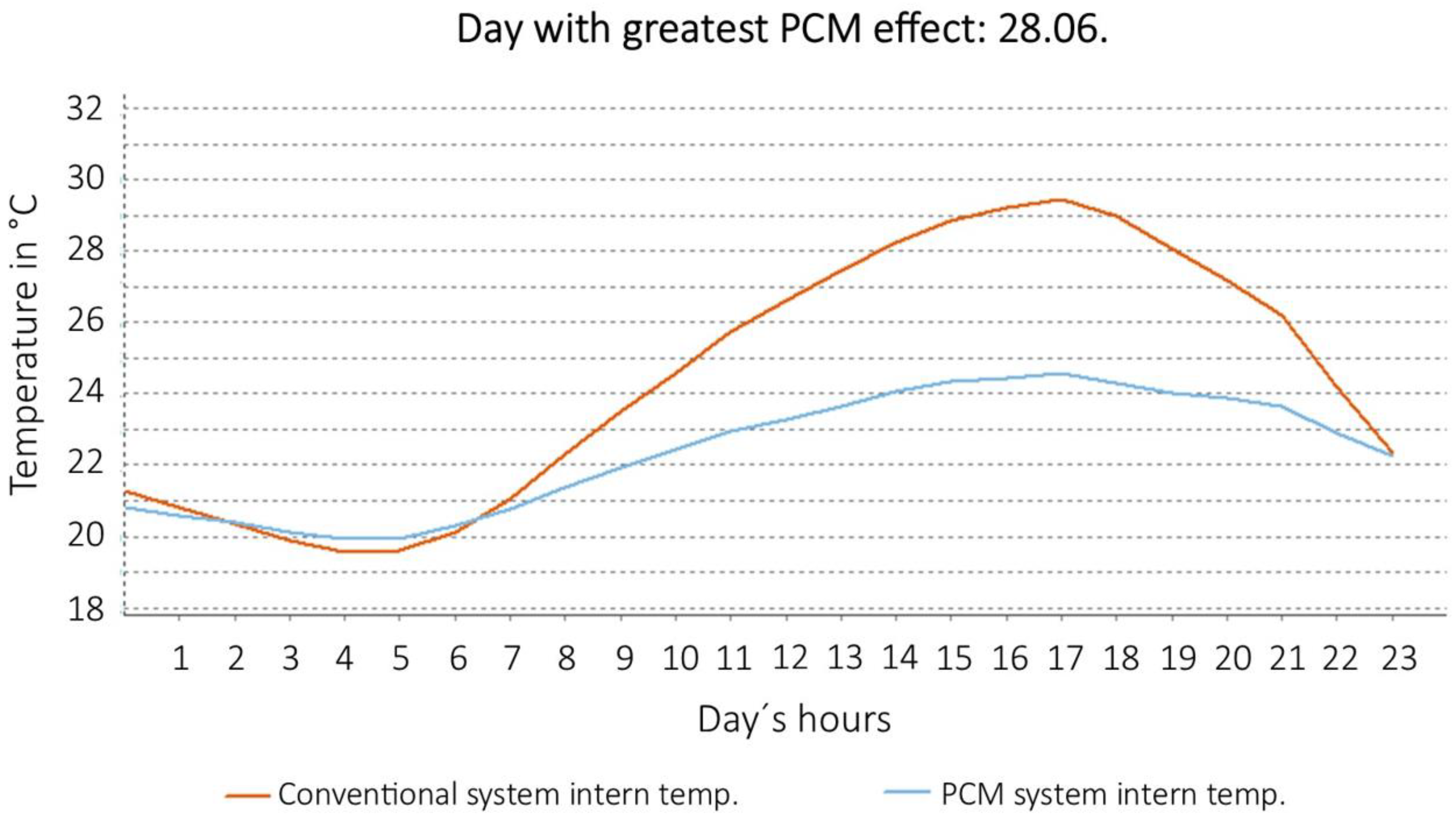
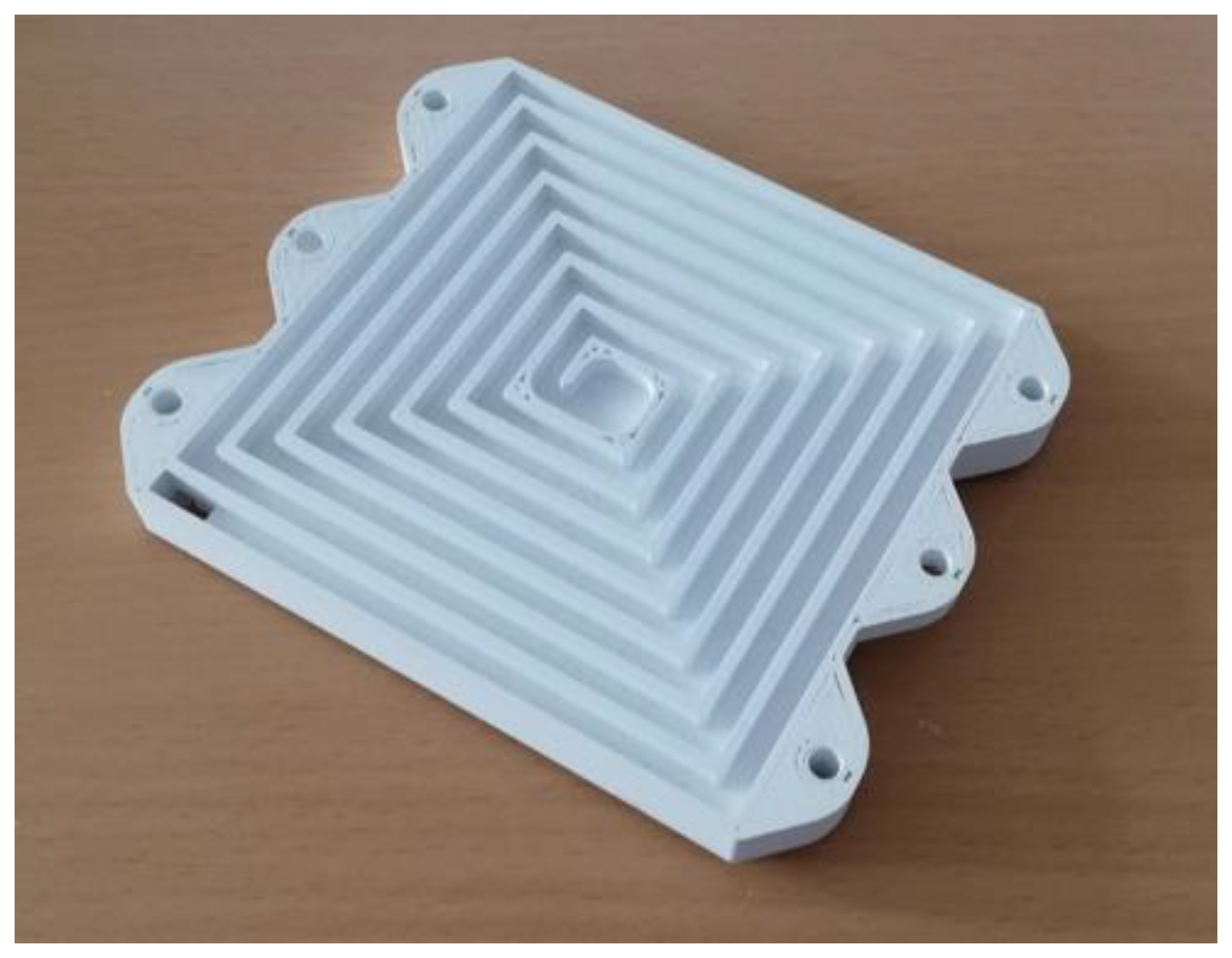
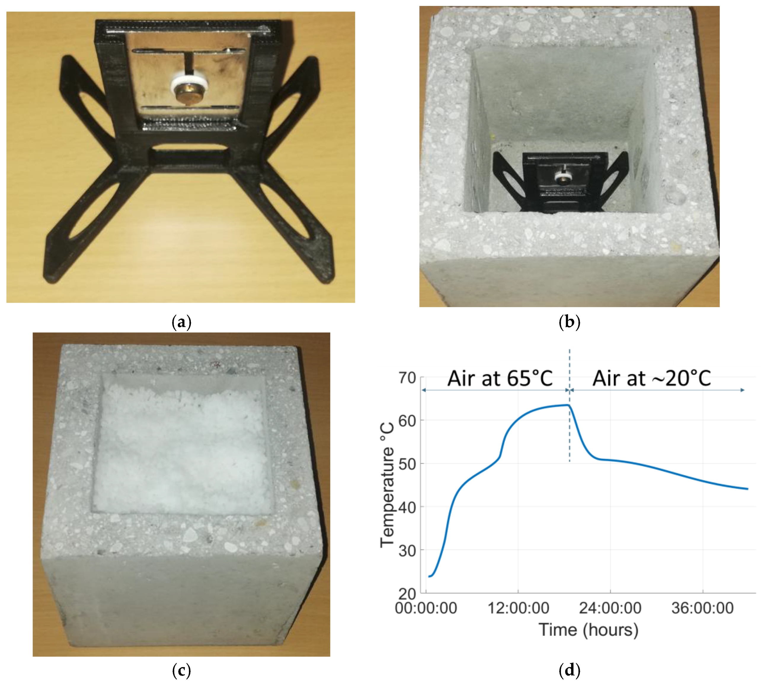
2.4. Phase-Change Materials for Passive Air Conditioning

Almost 25% of the energy produced worldwide is used to heat and cool homes and commercial buildings [86]. Therefore, passive cooling techniques are a highly promising family of solutions to help reduce the energy consumption of homes and buildings. Passive cooling techniques usually use large heat capacity materials (heat sinks), such as building materials or water, to mitigate temperature rises due to heat sources, such as hot ambient air, direct solar heat gain and internal heat gain [87]. Another way to massively expand the heat capacity of a building (in a pre-defined temperature range) is to incorporate phase-change materials (PCM) into building materials [88].
PCMs can store or release especially large amounts of thermal energy during the solid–liquid or liquid–solid phase transition. In Figure 4, we present the operating principle of an ideal PCM material (the curves do not correspond to real PCM materials) [89]. During phase transition, PCMs also absorb or release a predictable amount of thermal energy in a predictable amount of time [90]. When room temperature rises, excess heat gets absorbed (and stored) in the PCM, thanks to the endothermic solid–liquid transition. When room temperature falls again, the PCM releases the stored heat back into the room, thanks to the exothermic liquid–solid transition. This mechanism helps to (passively) stabilize the room temperature around the material’s transition temperature.
The ideal PCM for passive air conditioning applications must have a small volume change, be non-toxic and non-corrosive, have high thermal conductivity and specific heat capacity, and not supercool or decompose. Only PCMs that have a phase transition close to human comfort temperature can be used. This temperature is located between 18 and 24 °C [91]. Of the many available hydrated salts and organic PCMs, potassium fluoride tetrahydrate, calcium chloride hexahydrate, butylstearate, dodecanol, octadecane, propyl palmitate and capric-lauric acid are therefore possible candidates for passive air conditioning applications in buildings [92].
In order for PCM material to perform its thermal mitigation function during the day when it is hot, it needs to be regenerated (i.e., to return to the solid phase) at night. There are various options for regenerating the PCM: natural ventilation (by opening the windows), automatic ventilation using an air circulation system or cooling using water-cooled panels in direct contact with the PCM panels (surface activation).
PCMs are particularly well suited to passive air-conditioning applications in hot countries, such as sub-Saharan Africa, where the days are hot and the nights cold. However, they can also find applications in other parts of the world.
In the following section, we use a numerical study to illustrate the stabilizing effect of PCM panels in a typical residential room in Villach, southern Austria (see Figure 5). Real climatic data were used for this study. The software tool PCMexpress 1.0.3 was used for the computations (Valentin Software GmbH, www.valentin-software.com, accessed on 10 August 2023). In the simulation model, PCM panels cover the entire ceiling. In some of the simulations, they also cover the entire wall surface. Alba Balance 25 solid gypsum boards (ABG) were selected as PCM. The main technical characteristics of these PCM panels are shown in Table 1. The construction of the walls plays a major role, as it obviously influences the thermal capacity and conductivity of the walls, and therefore the heating/cooling demand. In our case, a simple construction (i.e., elevated/suspended reinforced concrete with 25 mm ABG) was selected.
Four different configurations were simulated: PCM in ceiling + manual ventilation (windows); PCM in ceiling + mechanical ventilation; PCM in ceiling and on the walls + manual ventilation; PCM in ceiling and on the walls + mechanical ventilation. For each configuration, we have calculated the effect of the PCM material, considering actual average climate data, in Villach. The simulation results are shown in Figure 6, Figure 7, Figure 8 and Figure 9. In each figure, the red curve shows the expected temperature profile inside the room without PCM. The blue curve shows the expected temperature profile with PCM (during the day of the year when the effect of the PCM would have been maximum).
Where PCM in the ceiling and with just manual ventilation can already reduce the maximum temperature, at the hottest hours, by almost 2 degrees (see Figure 6), the use of PCM in the ceiling and on the walls with mechanical ventilation can reduce the maximum temperature by almost 5 °C (Figure 9)! This demonstrates the interest in and great potential of PCMs for the passive air-conditioning of buildings. However, PCMs themselves are not, for most of them, “green” materials. Their installation also represents a non-negligible cost. We believe, however, that interest in PCMs can only grow from year to year, given the current socio-economic situation (worldwide) and the desire of many countries to rapidly decarbonize their economies.

2.5. Acoustic Metasurfaces for Green Acoustic Isolation

Metamaterials form a new class of materials whose physical properties derive essentially from their micro- or meso-structure, and not from their nature [93]. In particular, it is possible to manufacture metamaterials with properties unknown in nature, such as materials with a negative optical index [94]. In addition, the properties do not depend on the selected material (e.g., polymer, metal, ceramics).
Acoustic metasurfaces form a sub-class of metamaterials. Their ability to manipulate acoustic waves (passively) by means of structured plates that are very thin in relation to the wavelength gives them very interesting properties for “green acoustic” applications. They could indeed replace standard acoustic panels, often made of a wooden panel with holes masking a thick layer of absorbent porous material. Metasurface panels can attenuate sound (even at low frequency) without the need for this absorbent layer, often made from materials that are difficult to recycle, such as glass wool or polyurethane [95]. They could thus provide a green acoustic insulation solution for tomorrow’s buildings. Metasurfaces are designed to control the characteristics of reflected and transmitted waves, while having a sub-wavelength thickness [96]. Research in this field has progressed considerably in recent years, thanks in particular to the development of rapid prototyping techniques for complex geometries using additive manufacturing.
Acoustic metasurfaces can be used to manipulate the angles of reflection and transmission of incident waves, making it possible, for example, to generate large sound-free areas [97,98,99,100]. These surfaces are made up of geometric patterns designed to interact with incident waves. However, the patterns must have a characteristic size close to a quarter of a wavelength, which limits the application to low frequencies only. Other metasurfaces modify wave reflection and transmission coefficients at their interface [99] or directly absorb incident waves. Some of these absorbing metasurfaces are based on soft and flexible resonating membranes that can damp low-frequency acoustic waves [100,101]. However, these membranes are often fragile, which limits their range of application. Another category of absorbing metasurfaces is based on the Helmholtz resonator principle [102,103,104,105]. These resonators preferentially absorb and dissipate acoustic energy around their resonance frequency. This resonance frequency is inversely proportional to the volume of the resonant cavity, which limits the applications to low frequencies. However, it is possible to circumvent this issue by using “flattened” resonators where thin but wide cavities are used. A thin but long spiral waveguide (a coiled Helmholtz resonator) can also act as a resonant cavity. For illustration purposes, we present in Figure 10 an example of a flat, 3D-printed spiral waveguide. Such designs make it possible to absorb low frequencies down to 50 Hz, using structured plates with thicknesses significantly smaller than the wavelength [106,107,108]. One issue, however, is that absorption occurs only in a very narrow frequency range. Absorption in a wider frequency range requires the combination of several metasurface plates tuned to different frequencies (by adjusting their geometry). Despite this limitation, such metasurfaces could already be used to damp specific resonance modes, which can occur in concert halls, large offices or home studios.

2.6. Combination of Smart Materials

Combining several of the solutions discussed above is also a promising approach to developing high-added-value applications. One example is the possible combination of SMA-actuated solar curtains and PCM panels (e.g., inside the rooms) for passive air-conditioning in buildings. PCM materials could also be integrated into concrete walls. SAW sensors could then be used to measure (wirelessly and without embedded electronics) the temperature at the heart of the wall. Initially, this would help in the development of PCM-based solutions for different types of building, and/or different regions of the world. It could also be used to optimize the operation of an active air-conditioning system installed as a complement to the passive air-conditioning system.
Figure 11 shows the results of a feasibility study carried out in this field. A sensideon SAW ID-Tag sensor and its 3D-printed holder (see Figure 11a) were placed directly into a hollow, 15 cm × 15 cm × 15 cm concrete cube (Figure 11b), subsequently filled with PCM material in granulated form (Figure 11c). The walls are 2.5 cm thick. The phase transition temperature of the used PCM lies between 45 and 50 °C. The cube was then placed in a climatic chamber with the temperature set at 65 °C (the air within the chamber reaches this temperature within a few minutes). The heating was then turned off after 20 h. The experimental curve in Figure 11d shows the evolution of the temperature at the heart of the cube, obtained wirelessly and without embedded electronics, using the SAW sensor. The plateaus observed in the temperature rise and fall phases are due to the phase change of the PCM material. The PCM stabilizes the temperature in both directions. These results demonstrate the technical feasibility of the concept discussed in this paragraph and offer interesting prospects for applications.

3. Conclusions

In this paper, we have attempted to demonstrate the great potential of smart materials in the development of sustainable or green solutions for the cities of tomorrow. We have also highlighted the possibility of combining these different materials and solutions for (higher) added-value applications. Where appropriate, we have presented a number of new experimental results, some of which demonstrate the feasibility of innovative solutions based on smart materials. These solutions and experimental results will be the subject of more detailed publications in the near future. These publications will focus in particular on our recent work and results, obtained in the field of in-situ deformation measurement using SAW sensors integrated into concrete and PCM materials used for passive air-conditioning applications and thermal management of batteries for e-mobility. We hope that this short review paper will contribute to the development of sustainable and green technologies based on smart materials in the short, medium and long term.

Author Contributions

P.N. Conceptualization, writing—review and editing, Section 2.2 and Section 2.6; S.S. Section 2.1; S.M.T. Section 2.4; C.H. Section 2.5; B.F. Technical support. All authors have read and agreed to the published version of the manuscript.

Funding

This work was partially supported by Project i-MON (FFG COIN Funding Program, Projekt 884135, https://projekte.ffg.at/projekt/3984454, accessed on 10 August 2023).

Data Availability Statement

The Data presented in the present paper can be made available on demand. Please contact [email protected].

Acknowledgments

The authors would like to extend their warmest thanks to the whole CUAS FuCoSo team (https://forschung.fh-kaernten.at/fucoso/#team, accessed on 10 August 2023) for their outstanding technical support in the manufacture and testing of the concrete cubes, in which we integrated SAW sensors and PCM material. The authors would also like to warmly thank Martin Pierre for his highly helpful technical assistance in designing and carrying out some of the tests presented in Section 2.6.

Conflicts of Interest

The authors declare no conflict of interest.

References

  1. Holechek, J.L.; Geli, H.M.E.; Sawalhah, M.N.; Valdez, R. A Global Assessment: Can Renewable Energy Replace Fossil Fuels by 2050? Sustainability 2022, 14, 4792. [Google Scholar] [CrossRef]
  2. Kaluarachchi, Y. Implementing Data-Driven Smart City Applications for Future Cities. Smart Cities 2022, 5, 455–474. [Google Scholar] [CrossRef]
  3. Syed, A.S.; Sierra-Sosa, D.; Kumar, A.; Elmaghraby, A. IoT in Smart Cities: A Survey of Technologies, Practices and Challenges. Smart Cities 2021, 4, 429–475. [Google Scholar] [CrossRef]
  4. Martins, F.; Patrão, C.; Moura, P.; de Almeida, A.T. A Review of Energy Modeling Tools for Energy Efficiency in Smart Cities. Smart Cities 2021, 4, 1420–1436. [Google Scholar] [CrossRef]
  5. Gracias, J.S.; Parnell, G.S.; Specking, E.; Pohl, E.A.; Buchanan, R. Smart Cities—A Structured Literature Review. Smart Cities 2023, 6, 1719–1743. [Google Scholar] [CrossRef]
  6. Fernandez, C.A.; Correa, M.; Nguyen, M.-T.; Rod, K.A.; Dai, G.L.; Cosimbescu, L.; Rousseau, R.; Glezakou, V.-A. Progress and challenges in self-healing cementitious materials. J. Mater. Sci. 2020, 56, 201–230. [Google Scholar] [CrossRef]
  7. Hossain, R.; Sultana, R.; Patwary, M.M.; Khunga, N.; Sharma, P.; Shaker, S.J. Self-healing concrete for sustainable buildings. A review. Environ. Chem. Lett. 2022, 20, 1265–1273. [Google Scholar] [CrossRef]
  8. Amran, M.; Onaizi, A.M.; Fediuk, R.; Vatin, N.I.; Rashid, R.S.M.; Abdelgader, H.; Ozbakkaloglu, T. Self-Healing Concrete as a Prospective Construction Material: A Review. Materials 2022, 15, 3214. [Google Scholar] [CrossRef]
  9. De Belie, N.; Gruyaert, E.; Al-Tabbaa, A.; Antonaci, P.; Baera, C.; Bajare, D.; Darquennes, A.; Davies, R.; Ferrara, L.; Jefferson, T.; et al. A Review of Self-Healing Concrete for Damage Management of Structures. Adv. Mater. Interfaces 2018, 5, 1800074. [Google Scholar] [CrossRef]
  10. de Brito, J.; Kurda, R. The past and future of sustainable concrete: A critical review and new strategies on cement-based materials. J. Clean. Prod. 2021, 281, 123558. [Google Scholar] [CrossRef]
  11. Shah, K.W.; Huseien, G.F. Biomimetic Self-Healing Cementitious Construction Materials for Smart Buildings. Biomimetics 2020, 5, 47. [Google Scholar] [CrossRef] [PubMed]
  12. Kayondo, M.; Combrinck, R.; Boshoff, W. State-of-the-art review on plastic cracking of concrete. Constr. Build. Mater. 2019, 225, 886–899. [Google Scholar] [CrossRef]
  13. Roig-Flores, M.; Formagini, S.; Serna, P. Self-healing concrete-What Is it Good For? Mater. Constr. 2021, 71, e237. [Google Scholar] [CrossRef]
  14. Snoeck, D.; De Belie, N. Autogenous Healing in Strain-Hardening Cementitious Materials With and Without Superabsorbent Polymers: An 8-Year Study. Front. Mater. 2019, 6, 48. [Google Scholar] [CrossRef]
  15. Jiang, Z.; Li, W.; Yuan, Z. Influence of mineral additives and environmental conditions on the self-healing capabilities of cementitious materials. Cem. Concr. Compos. 2015, 57, 116–127. [Google Scholar] [CrossRef]
  16. Tang, W.; Kardani, O.; Cui, H. Robust evaluation of self-healing efficiency in cementitious materials—A review. Constr. Build. Mater. 2015, 81, 233–247. [Google Scholar] [CrossRef]
  17. Reinhardt, H.W.; Jonkers, H.; Van Tittelboom, K.; Snoeck, D.; De Belie, N.; De Muynck, W.; Verstraete, W.; Wang, J.; Mechtcherine, V. RILEM State-of-the-Art Reports; Rooji, M., Tittelboom, K., Belie, N., Schlangen, E., Eds.; Springer: New York, NY, USA, 2013; Volume 11, pp. 65–117. [Google Scholar]
  18. Li, W.; Dong, B.; Yang, Z.; Xu, J.; Chen, Q.; Li, H.; Xing, F.; Jiang, Z. Recent Advances in Intrinsic Self-Healing Cementitious Materials. Adv. Mater. 2018, 30, e1705679. [Google Scholar] [CrossRef]
  19. Wiktor, V.; Jonkers, H.M. Quantification of crack-healing in novel bacteria-based self-healing concrete. Cem. Concr. Compos. 2011, 33, 763–770. [Google Scholar] [CrossRef]
  20. Joshi, S.; Goyal, S.; Mukherjee, A.; Reddy, M.S. Microbial healing of cracks in concrete: A review. J. Ind. Microbiol. Biotechnol. 2017, 44, 1511–1525. [Google Scholar] [CrossRef]
  21. Erşan, Y.; Hernandez-Sanabria, E.; Boon, N.; de Belie, N. Enhanced crack closure performance of microbial mortar through nitrate reduction. Cem. Concr. Compos. 2016, 70, 159–170. [Google Scholar] [CrossRef]
  22. Wang, J.; Soens, H.; Verstraete, W.; De Belie, N. Self-healing concrete by use of microencapsulated bacterial spores. Cem. Concr. Res. 2014, 56, 139–152. [Google Scholar] [CrossRef]
  23. Bhaskar, S.; Hossain, K.M.A.; Lachemi, M.; Wolfaardt, G.; Kroukamp, M.O. Effect of self-healing on strength and durability of zeolite-immobilized bacterial cementitious mortar composites. Cem. Concr. Compos. 2017, 82, 23–33. [Google Scholar] [CrossRef]
  24. Justo-Reinoso, I.; Heath, A.; Gebhard, S.; Paine, K. Aerobic non-ureolytic bacteria-based self-healing cementitious composites: A comprehensive review. J. Build. Eng. 2021, 42, 102834. [Google Scholar] [CrossRef]
  25. Xu, J.; Wang, X.; Wang, B. Biochemical process of ureolysis-based microbial CaCO3 precipitation and its application in self-healing concrete. Appl. Microbiol. Biotechnol. 2018, 102, 3121–3132. [Google Scholar] [CrossRef]
  26. Sarkar, M.; Adak, D.; Tamang, A.; Chattopadhyay, B.; Mandal, S. Genetically-enriched microbe-facilitated self-healing concrete—A sustainable material for a new generation of construction technology. RSC Adv. 2015, 5, 105363–105371. [Google Scholar] [CrossRef]
  27. Jonkers, H.M.; Thijssen, A.; Muyzer, G.; Copuroglu, O.; Schlangen, E. Application of bacteria as self-healing agent for the development of sustainable concrete. Ecol. Eng. 2010, 36, 230–235. [Google Scholar] [CrossRef]
  28. Yang, N.; Sun, Q. Study on the Self-Monitoring of Bending Fatigue Cumulative Damage for Carbon Nanofiber Polyurethane Cement. Appl. Sci. 2019, 9, 2128. [Google Scholar] [CrossRef]
  29. Soydan, A.M.; Sari, A.K.; Duymaz, B.; Akdeniz, R.; Tunaboylu, B. Air-Cured Fiber-Cement Composite Mixtures with Different Types of Cellulose Fibers. Adv. Mater. Sci. Eng. 2018, 2018, 3841514. [Google Scholar] [CrossRef]
  30. Al-Hadithi, A.I.; Noaman, A.T.; Mosleh, W.K. Mechanical properties and impact behavior of PET fiber reinforced self-compacting concrete (SCC). Compos. Struct. 2019, 224, 111021. [Google Scholar] [CrossRef]
  31. Guzlena, S.; Sakale, G. Self-healing of glass fibre reinforced concrete (GRC) and polymer glass fibre reinforced concrete (PGRC) using crystalline admixtures. Constr. Build. Mater. 2021, 267, 120963. [Google Scholar] [CrossRef]
  32. Khan, R. Fiber bridging in composite laminates: A literature review. Compos. Struct. 2019, 229, 111418. [Google Scholar] [CrossRef]
  33. Homma, D.; Mihashi, H.; Nishiwaki, T. Self-Healing Capability of Fibre Reinforced Cementitious Composites. J. Adv. Concr. Technol. 2009, 7, 217–228. [Google Scholar] [CrossRef]
  34. Xue, C.; Li, W.; Li, J.; Tam, V.W.Y.; Ye, G. A review study on encapsulation-based self-healing for cementitious materials. Struct. Concr. 2018, 20, 198–212. [Google Scholar] [CrossRef]
  35. Mostavi, E.; Asadi, S.; Hassan, M.M.; Alansari, M. Evaluation of Self-Healing Mechanisms in Concrete with Double-Walled Sodium Silicate Microcapsules. J. Mater. Civ. Eng. 2015, 27. [Google Scholar] [CrossRef]
  36. Ni, Z.; Du, X.X.; Wang, S.; Xing, F.; Huang, Z. Effect of UF/Epoxy Microcapsules on Cement Composite. Adv. Mater. Res. 2012, 443–444, 700–704. [Google Scholar] [CrossRef]
  37. Lv, L.; Yang, Z.; Chen, G.; Zhu, G.; Han, N.; Schlangen, E.; Xing, F. Synthesis and characterization of a new polymeric microcapsule and feasibility investigation in self-healing cementitious materials. Constr. Build. Mater. 2016, 105, 487–495. [Google Scholar] [CrossRef]
  38. Van Tittelboom, K.; De Belie, N.; Van Loo, D.; Jacobs, P. Self-healing efficiency of cementitious materials containing tubular capsules filled with healing agent. Cem. Concr. Compos. 2011, 33, 497–505. [Google Scholar] [CrossRef]
  39. Van Tittelboom, K.; Tsangouri, E.; Van Hemelrijck, D.; De Belie, N. The efficiency of self-healing concrete using alternative manufacturing procedures and more realistic crack patterns. Cem. Concr. Compos. 2015, 57, 142–152. [Google Scholar] [CrossRef]
  40. Araújo, M.; Chatrabhuti, S.; Gurdebeke, S.; Alderete, N.; Van Tittelboom, K.; Raquez, J.-M.; Cnudde, V.; Van Vlierberghe, S.; De Belie, N.; Gruyaert, E. Poly(methyl methacrylate) capsules as an alternative to the ‘’proof-of-concept’’ glass capsules used in self-healing concrete. Cem. Concr. Compos. 2018, 89, 260–271. [Google Scholar] [CrossRef]
  41. Joseph, C.; Jefferson, A.; Isaacs, B.; Lark, R.; Gardner, D.; Al-Tabbaa, A.; Harbottle, M.J.; Yi, S.-T.; Heo, G.; Edvardsen, C. Experimental investigation of adhesive-based self-healing of cementitious materials. Mag. Concr. Res. 2010, 62, 831–843. [Google Scholar] [CrossRef]
  42. Yang, Z.; Hollar, J.; He, X.; Shi, X. A self-healing cementitious composite using oil core/silica gel shell microcapsules. Cem. Concr. Compos. 2011, 33, 506–512. [Google Scholar] [CrossRef]
  43. Lucas, S.; Moxham, C.; Tziviloglou, E.; Jonkers, H. Study of self-healing properties in concrete with bacteria encapsulated in expanded clay. Sci. Technol. Mater. 2018, 30, 93–98. [Google Scholar] [CrossRef]
  44. Gilford, J.; Hassan, M.M.; Rupnow, T.; Barbato, M.; Okeil, A.; Asadi, S. Dicyclopentadiene and Sodium Silicate Microencapsulation for Self-Healing of Concrete. J. Mater. Civ. Eng. 2014, 26, 886–896. [Google Scholar] [CrossRef]
  45. Gao, J.; Jin, P.; Zhang, Y.; Dong, H.; Wang, R. Fast-responsive capsule based on two soluble components for self-healing concrete. Cem. Concr. Compos. 2022, 133, 104711. [Google Scholar] [CrossRef]
  46. Minnebo, P.; Thierens, G.; De Valck, G.; Van Tittelboom, K.; De Belie, N.; Van Hemelrijck, D.; Tsangouri, E. A Novel Design of Autonomously Healed Concrete: Towards a Vascular Healing Network. Materials 2017, 10, 49. [Google Scholar] [CrossRef]
  47. Tsangouri, E.; Van Loo, C.; Shields, Y.; De Belie, N.; Van Tittelboom, K.; Aggelis, D.G. Reservoir-Vascular Tubes Network for Self-Healing Concrete: Performance Analysis by Acoustic Emission, Digital Image Correlation and Ultrasound Velocity. Appl. Sci. 2022, 12, 4821. [Google Scholar] [CrossRef]
  48. Kuang, Y.; Ou, J. Self-repairing performance of concrete beams strengthened using superelastic SMA wires in combination with adhesives released from hollow fibers. Smart Mater. Struct. 2008, 17, 025020. [Google Scholar] [CrossRef]
  49. Jefferson, A.; Joseph, C.; Lark, R.; Isaacs, B.; Dunn, S.; Weager, B. A new system for crack closure of cementitious materials using shrinkable polymers. Cem. Concr. Res. 2010, 40, 795–801. [Google Scholar] [CrossRef]
  50. Song, G.; Ma, N.; Li, H.-N. Applications of shape memory alloys in civil structures. Eng. Struct. 2006, 28, 1266–1274. [Google Scholar] [CrossRef]
  51. Duerig, T.W.; Melton, K.N.; Stockel, D.; Wayman, C.M. Engineering Aspects of Shape Memory Alloys, 1st ed.; Elsevier Science (Verlag): Amsterdam, The Netherlands, 2013; ISBN 9781483144757. [Google Scholar]
  52. Goyal, M.; Agarwal, S.N.; Bhatnagar, N. A review on self-healing polymers for applications in spacecraft and construction of roads. J. Appl. Polym. Sci. 2022, 139, e52816. [Google Scholar] [CrossRef]
  53. Snoeck, D.; Van Tittelboom, K.; Steuperaert, S.; Dubruel, P.; De Belie, N. Self-healing cementitious materials by the combination of microfibres and superabsorbent polymers. J. Intell. Mater. Syst. Struct. 2012, 25, 13–24. [Google Scholar] [CrossRef]
  54. Cash, J.J.; Kubo, T.; Bapat, A.P.; Sumerlin, B.S. Room-Temperature Self-Healing Polymers Based on Dynamic-Covalent Boronic Esters. Macromolecules 2015, 48, 2098–2106. [Google Scholar] [CrossRef]
  55. Xia, W.; Xu, Z.; Xu, T. Self-healing behaviors and its effectiveness evaluations of fiber reinforced shape memory polyurethane/SBS modified asphalt mortar. Case Stud. Constr. Mater. 2023, 18, e01784. [Google Scholar] [CrossRef]
  56. Morlat, R.; Orange, G.; Bomal, Y.; Godard, P. Reinforcement of hydrated portland cement with high molecular mass water-soluble polymers. J. Mater. Sci. 2007, 42, 4858–4869. [Google Scholar] [CrossRef]
  57. An, S.; Lee, M.W.; Yarin, A.L.; Yoon, S.S. A review on corrosion-protective extrinsic self-healing: Comparison of microcapsule-based systems and those based on core-shell vascular networks. Chem. Eng. J. 2018, 344, 206–220. [Google Scholar] [CrossRef]
  58. Wack, H.; Bertling, J. Water-swellable materials–application in self-healing sealing systems. In Proceedings of the First International Conference on Self Healing Materials, Dordrecht, The Netherlands, 18–20 April 2007; Springer: Berlin/Heidelberg, Germany, 2007; Volume 9. [Google Scholar]
  59. Wang, Y.; Li, Y.; Zhang, Z.; Zhang, Y. Effect of Doping Microcapsules on Typical Electrical Performances of Self-Healing Polyethylene Insulating Composite. Appl. Sci. 2019, 9, 3039. [Google Scholar] [CrossRef]
  60. Scheiner, M.; Dickens, T.J.; Okoli, O. Progress towards self-healing polymers for composite structural applications. Polymer 2016, 83, 260–282. [Google Scholar] [CrossRef]
  61. Cantini, A.; Leoni, L.; De Carlo, F.; Salvio, M.; Martini, C.; Martini, F. Technological Energy Efficiency Improvements in Cement Industries. Sustainability 2021, 13, 3810. [Google Scholar] [CrossRef]
  62. Latawiec, R.; Woyciechowski, P.; Kowalski, K. Sustainable Concrete Performance—CO2-Emission. Environments 2018, 5, 27. [Google Scholar] [CrossRef]
  63. Available online: https://www.fprimec.com/sensors-for-structural-health-monitoring/ (accessed on 18 July 2023).
  64. Ferreira, P.M.; Machado, M.A.; Carvalho, M.S.; Vidal, C. Embedded Sensors for Structural Health Monitoring: Methodologies and Applications Review. Sensors 2022, 22, 8320. [Google Scholar] [CrossRef]
  65. Nicolay, P.; Chambon, H.; Bruckner, G. Simulation of the properties and behaviour of a passive and wireless Surface Acoustic Wave RFID Tag, for structural health monitoring applications. In Proceedings of the VIII ECCOMAS Thematic Conference on Smart Structures and Materials, SMART 2017, Madrid, Spain, 5–8 June 2017; pp. 1444–1452. [Google Scholar]
  66. Nicolay, P.; Chambon, H.; Bruckner, G. SAW RFID sensors and devices for industrial applications, a short review. In Proceedings of the 7th edition of the International Symposium on Air/Craft Materials (ACMA), Compiègne, France, 24–26 April 2018; pp. 475–481. [Google Scholar]
  67. Mandal, D.; Banerjee, S. Surface Acoustic Wave (SAW) Sensors: Physics, Materials, and Applications. Sensors 2022, 22, 820. [Google Scholar] [CrossRef]
  68. Devkota, J.; Ohodnicki, P.R.; Greve, D.W. SAW Sensors for Chemical Vapors and Gases. Sensors 2017, 17, 801. [Google Scholar] [CrossRef] [PubMed]
  69. Plessky, V.P.; Reindl, L.M. Review on SAW RFID tags. IEEE Trans. Ultrason. Ferroelectr. Freq. Control 2010, 57, 654–668. [Google Scholar] [CrossRef] [PubMed]
  70. Bruckner, G.; Bardong, J.; Binder, A.; Nicolay, P. SAW Delay Lines as Wireless Sensors for Industrial Applications. In Proceedings of the VIII ECCOMAS Thematic Conference on Smart Structures and Materials, SMART 2017, Madrid, Spain, 5–8 June 2017; pp. 1433–1443. [Google Scholar]
  71. Huang, H.; Yuan, Y.; Zhang, W.; Zhu, L. Property Assessment of High-Performance Concrete Containing Three Types of Fibers. Int. J. Concr. Struct. Mater. 2021, 15, 39. [Google Scholar] [CrossRef]
  72. Zhang, C.; Khorshidi, H.; Najafi, E.; Ghasemi, M. Fresh, mechanical and microstructural properties of alkali-activated composites incorporating nanomaterials: A comprehensive review. J. Clean. Prod. 2023, 384, 135390. [Google Scholar] [CrossRef]
  73. Czechowicz, A.; Langbein, S. Shape Memory Alloy Valves; Springer: Cham, Switzerland, 2015. [Google Scholar] [CrossRef]
  74. Yoneyama, T.; Miyazaki, S. Shape Memory Alloys for Biomedical Applications, 1st ed.; Woodhead: Sawston, UK, 2008; ISBN 9781845695248. [Google Scholar]
  75. Hartl, D.J.; Lagoudas, D.C. Aerospace applications of shape memory alloys. Proc. Inst. Mech. Eng. Part G J. Aerosp. Eng. 2007, 221, 535–552. [Google Scholar] [CrossRef]
  76. Zareie, S.; Issa, A.S.; Seethaler, R.J.; Zabihollah, A. Recent advances in the applications of shape memory alloys in civil infrastructures: A review. Structures 2020, 27, 1535–1550. [Google Scholar] [CrossRef]
  77. Available online: https://www.hoffmann-kunststoffe.de/aktor-fg-one/ (accessed on 10 August 2023).
  78. Kabelklemme Konzept, Fraunhofer Institute IWU, Desden, Germany. Available online: https://st4sd.de/wp-content/uploads/2016/05/160417_FSK001-FSK048.pdf(FSK10) (accessed on 10 August 2023).
  79. Available online: https://en.wikipedia.org/wiki/Vulnerability_of_nuclear_plants_to_attack (accessed on 10 August 2023).
  80. Guadalupe, J.A.; Copaci, D.; del Cerro, D.S.; Moreno, L.; Blanco, D. Efficiency Analysis of SMA-Based Actuators: Possibilities of Configuration According to the Application. Actuators 2021, 10, 63. [Google Scholar] [CrossRef]
  81. Project Solar Curtain, Weißensee Kunsthochschule Berlin und Fraunhofer Institute IWU Dresden. Available online: https://www.barafinnsdottir.com/solar-curtain-demonstrator (accessed on 12 July 2023).
  82. Available online: https://www.nasa.gov/specials/wheels/ (accessed on 12 July 2023).
  83. Qian, S.; Geng, Y.; Wang, Y.; Ling, J.; Hwang, Y.; Radermacher, R.; Takeuchi, I.; Cui, J. A review of elastocaloric cooling: Materials, cycles and system integrations. Int. J. Refrig. 2016, 64, 1–19. [Google Scholar] [CrossRef]
  84. Welsch, F.; Kirsch, S.-M.; Michaelis, N.; Schmidt, M.; Schütze, A.; Seelecke, S. Continuously operating elastocaloric cooling device based on shape memory alloys: Development and realization. In Proceedings of the 8th International Conference on Magnetic Refrigeration at Room Temperature (Thermag VIII), Darmstadt, Germany, 16–20 September 2018. [Google Scholar] [CrossRef]
  85. Christodoulides, P.; Agathokleous, R.; Aresti, L.; Kalogirou, S.A.; Tassou, S.A.; Florides, G.A. Waste Heat Recovery Technologies Revisited with Emphasis on New Solutions, Including Heat Pipes, and Case Studies. Energies 2022, 15, 384. [Google Scholar] [CrossRef]
  86. International Energy Agency: “Global Status Report for Buildings and Construction 2019.” This Report Finds That Residential and Commercial Buildings Accounted for 30% of Global Energy Use, and 28% of Global Greenhouse Gas Emissions from Energy and Industrial Use, in 2018. Around Four-Fifths of That Energy Was Used for Cooling and Heating, Including Cooking and Heating Water. The Rest Is Attributed to Lighting and Appliances. Available online: https://climate.mit.edu/explainers/heating-and-cooling (accessed on 10 August 2023).
  87. Bhamare, D.K.; Rathod, M.K.; Banerjee, J. Passive cooling techniques for building and their applicability in different climatic zones—The state of art. Energy Build. 2019, 198, 467–490. [Google Scholar] [CrossRef]
  88. Adesina, A. Use of phase change materials in concrete: Current challenges. Renew. Energy Environ. Sustain. 2019, 4, 9. [Google Scholar] [CrossRef]
  89. Hauer, A.; Hiebler, S.; Reuß, M. Wärmespeicher; Fraunhofer IRB Verlag: Stuttgart, Germany, 2012; ISBN 978-3-8167-8366-4. [Google Scholar]
  90. Sterner, M.; Stadler, I. Energiespeicher im Wandel der Zeit. In Energiespeicher—Bedarf, Technologien, Integration; Springer: Berlin/Heidelberg, Germany, 2017; pp. 3–24. [Google Scholar] [CrossRef]
  91. Frank, W. Raumklima und Thermische Behaglichkeit. In Berichte aus der Bauforschung, Heft 104; Ernst & Sohn Verlag: Berlin, Germany, 1975. [Google Scholar]
  92. Khudhair, A.M.; Farid, M.M. A review on energy conservation in building applications with thermal storage by latent heat using phase change materials. Energy Convers. Manag. 2004, 45, 263–275. [Google Scholar] [CrossRef]
  93. Available online: https://en.wikipedia.org/wiki/Metamaterial (accessed on 21 July 2023).
  94. Marqués, R.; Martín, F.; Sorolla, M. Metamaterials with Negative Parameters: Theory, Design, and Microwave Applications; Wiley: Hoboken, NJ, USA, 2008; ISBN 978-0-471-74582-2. [Google Scholar]
  95. Yang, M.; Chen, S.; Fu, C.; Sheng, P. Optimal sound-absorbing structures. Mater. Horiz. 2017, 4, 673–680. [Google Scholar] [CrossRef]
  96. Assouar, B.; Liang, B.; Wu, Y.; Li, Y.; Cheng, J.-C.; Jing, Y. Acoustic metasurfaces. Nat. Rev. Mater. 2018, 3, 460–472. [Google Scholar] [CrossRef]
  97. Ge, Y.; Sun, H.-X.; Yuan, S.-Q.; Lai, Y. Switchable omnidirectional acoustic insulation through open window structures with ultrathin metasurfaces. Phys. Rev. Mater. 2019, 3, 065203. [Google Scholar] [CrossRef]
  98. Ge, Y.; Sun, H.-X.; Yuan, S.-Q.; Lai, Y. Broadband unidirectional and omnidirectional bidirectional acoustic insulation through an open window structure with a metasurface of ultrathin hooklike meta-atoms. Appl. Phys. Lett. 2018, 112, 243502. [Google Scholar] [CrossRef]
  99. Song, X.; Chen, T.; Zhu, J.; He, Y.; Zhang, J. A Switchable Sound Tunnel by Using an Acoustic Metasurface. J. Theor. Comput. Acoust. 2019, 27, 1950015. [Google Scholar] [CrossRef]
  100. Han, L.-X.; Yao, Y.-W.; Zhang, X.; Wu, F.-G.; Dong, H.-F.; Mu, Z.-F.; Li, J.-B. Acoustic metasurface for refracted wave manipulation. Phys. Lett. A 2018, 382, 357–361. [Google Scholar] [CrossRef]
  101. Yu, X.; Lu, Z.; Cheng, L.; Cui, F. On the sound insulation of acoustic metasurface using a sub-structuring approach. J. Sound Vib. 2017, 401, 190–203. [Google Scholar] [CrossRef]
  102. Zhang, H.; Xiao, Y.; Wen, J.; Yu, D.; Wen, X. Ultra-thin smart acoustic metasurface for low-frequency sound insulation. Appl. Phys. Lett. 2016, 108, 141902. [Google Scholar] [CrossRef]
  103. Ma, G.; Yang, M.; Xiao, S.; Yang, Z.; Sheng, P. Acoustic metasurface with hybrid resonances. Nat. Mater. 2014, 13, 873–878. [Google Scholar] [CrossRef]
  104. Duan, M.; Yu, C.; Xu, Z.; Xin, F.; Lu, T.J. Acoustic impedance regulation of Helmholtz resonators for perfect sound absorption via roughened embedded necks. Appl. Phys. Lett. 2020, 117, 151904. [Google Scholar] [CrossRef]
  105. Komkin, A.I.; Mironov, M.A.; Bykov, A.I. Sound absorption by a Helmholtz resonator. Acoust. Phys. 2017, 63, 385–392. [Google Scholar] [CrossRef]
  106. Schnitzer, O.; Brandão, R. Absorption characteristics of large acoustic metasurfaces. Philos. Trans. R. Soc. A 2022, 380, 20210399. [Google Scholar] [CrossRef] [PubMed]
  107. Jiménez, N.; Huang, W.; Romero-García, V.; Pagneux, V.; Groby, J.-P. Ultra-thin metamaterial for perfect and quasi-omnidirectional sound absorption. Appl. Phys. Lett. 2016, 109, 121902. [Google Scholar] [CrossRef]
  108. Donda, K.; Zhu, Y.; Fan, S.-W.; Cao, L.; Li, Y.; Assouar, B. Extreme low-frequency ultrathin acoustic absorbing metasurface. Appl. Phys. Lett. 2019, 115, 173506. [Google Scholar] [CrossRef]
Figure 1. Integration of a 2.45 GHz sensideon SAW ID-Tag sensor in concrete: (a) SAW ID-Tag with its antenna; (b) sensor and protecting housing, in formwork, prior to casting; (c) casting and shaking of concrete, to ensure proper concrete compaction; (d) concrete cube, with embedded sensor.
Applsci 13 09289 g001
Figure 2. In situ temperature measurement in a small concrete block: (a) Maximum interrogation distance, at the end of the solidification (maturation) phase; (b) temperature data, over time, during solidification phase (data were acquired between 28 February and 2 March 2022).
Applsci 13 09289 g002
Figure 3. SMA actuator (a) Test bench. A Hall sensor is used to measure the vertical displacement of the moving part (in red), to which the weight is attached. The white arrow points to the two cables used to heat the NiTinol wire using DC current; (b) observed vertical displacement over time using a heating current of 3 A and a weight of 0.5 kg. The power supply is automatically switched off immediately after actuation. The wire is then left to cool (passive air cooling). It returns to its initial position after about 4 s.
Applsci 13 09289 g003
Figure 4. Stored heat around Tm (typical curves). Red: PCM with a solid–liquid transition temperature Tm; Blue: standard material, with no phase change, in the considered temperature range.
Applsci 13 09289 g004
Figure 5. Sample room geometry. Windows cover 40% of the south side wall (not shown on the schematics).
Applsci 13 09289 g005
Figure 6. PCM in ceiling + manual ventilation (i.e., open windows, during the night) on the 23rd of August.
Applsci 13 09289 g006
Figure 7. PCM in ceiling + mechanical ventilation (during the night) on the 4th of June.
Applsci 13 09289 g007
Figure 8. PCM in ceiling and on the walls + manual ventilation (i.e., open windows, during the night) on the 23rd of August.
Applsci 13 09289 g008
Figure 9. PCM in ceiling and on the walls + mechanical ventilation (during the night) on the 28th of June.
Applsci 13 09289 g009
Figure 10. Example of a 3D-printed coiled Helmholtz resonator. The inlet is located in the center. A plate with a hole in its center (not shown) is used to seal the resonator.
Applsci 13 09289 g010
Figure 11. Integration of a sensideon SAW ID-Tag sensor in a hollow concrete cube, filled with PCM granulates: (a) SAW ID-Tag with its 3D-printed support; (b) sensor and support within the cube; (c) cube filled with PCM granulates; (d) temperature evolution within the PCM material, measured with the SAW sensor. The cube was placed in a climatic chamber with a set temperature of 65 °C. The reader’s antenna was also placed in the climate chamber approximately ten centimeters away from the cube’s surface. After 20 h, the temperature inside the climate chamber was set to 20 °C.
Applsci 13 09289 g011
Table 1. Physical properties of Alba Balance 25 PCM material (Rigips AG, https://www.rigips.ch/de/produkte/alba/balance, Prospekt Alba Balance, p. 24 (accessed on 10 August 2023).
TypeMelting Point
[°C]
Latent Heat
[kJ/m2]
Specific Heat [kJ/m2K]Panel Size
w × l × t [mm]
Weight per UNIT AREA
[kg/m²]
Alba balance 2525 °C ± 1 °C30626.7500 × 1000 × 2523
Disclaimer/Publisher’s Note: The statements, opinions and data contained in all publications are solely those of the individual author(s) and contributor(s) and not of MDPI and/or the editor(s). MDPI and/or the editor(s) disclaim responsibility for any injury to people or property resulting from any ideas, methods, instructions or products referred to in the content.

