Article

The Incorporation of Waste Sludge into the Production of High-Temperature-Resistant Adhesive Ceramic Materials

1
Institute of Nuclear Sciences “Vinča”-National Institute of the Republic of Serbia, University of Belgrade, 22-24 Mike Petrovića Alasa, 11351 Belgrade, Serbia
2
Institute for Multidisciplinary Research, University of Belgrade, Kneza Višeslava 1, 11030 Belgrade, Serbia
3
Department of Science and Technology for Sustainable Development and One Health, Università Campus Bio-Medico di Roma, Via Álvaro del Portillo 21, 00128 Rome, Italy
*
Author to whom correspondence should be addressed.
Appl. Sci. 2023, 13(16), 9044; https://doi.org/10.3390/app13169044
Submission received: 4 July 2023 / Revised: 1 August 2023 / Accepted: 4 August 2023 / Published: 8 August 2023
(This article belongs to the Special Issue Advanced Research of Bio-Waste and Industrial Waste Management)

Abstract

:
In recent years, the interest of the scientific community has become focused on the integration of circular economy principles by eliminating end-of-life concepts and forming zero-waste strategies. The present paper suggests the possible application of innovative, eco-friendly, cost-effective, and highly efficient ceramic materials with the partial implementation of aluminosilicate-based waste in the form of wastewater sludge in advanced technology solutions. The specific objective was to demonstrate the effective utilization of the investigated waste in the production of refractory adhesives and/or sealants for Intermediate-Temperature Solid-Oxide Fuel Cells (IT-SOFCs). Different physical–mechanical and chemical properties were determined along with the performance of leaching tests, the thermal cycling procedure, and leakage tests in a single cell. Based on the maintenance of mechanical integrity after thermal cycling and satisfying crystal and microstructural stability after high-temperature treatment, it was concluded that the investigated materials may be considered promising candidates for application as heat-resistant adhesives for connecting components in heating systems. However, they were not found to be applicable as sealants for IT-SOFCs in raw form according to the failure of testing in a single cell. Still, requirements for this purpose could be met after certain modifications of the composition and synthesis methodology, which presents the major initiative for our further research in this field.

1. Introduction

The level of industrialization is considered to be an important reflection of the growing economic power of a nation [1]. However, although it presents a vital indicator of technological development, the rapid industrial revolution has a major harmful impact on the environment due to millions of tons of potentially hazardous and toxic waste materials, which are being generated in industrial processes each year on a global scale [1,2,3,4]. Waste sludge from industrial wastewater treatment plants is one such ecologically undesirable by-product, and is also regarded as one of the largest solid waste streams originating from wastewater-related technological operations [5]. Owing to the rather problematic chemical composition, industrial wastewater sludge has long been considered unsafe for the environment [5,6,7]. Hence, very stringent environmental regulations and high-cost legal practices are established for the purpose of avoiding the endangerment of the environment due to the production of such a widely presented waste product [8,9].
Nowadays, there is a tendency in modern society, especially among the scientific community, towards contributing to the sustainability and the transition of the current linear economy to a circular economy [10,11,12,13]. In this context, the fundamental goal is based on the transformation of recyclable wastes into valuable raw materials, which may be effectively used for different industrial applications. Accordingly, the reuse of industrial by-products and other waste streams as alternative Supplementary materials can promote sustainable development in different industrial fields and be beneficial from both economic and environmental points of view [6].
In general, an extensive literature survey evidenced that wastewater sludge is being widely investigated for a broad range of effective applications in numerous engineering fields. It has been reported to possess great potential to be applied as a component of construction materials [14,15,16,17], as an adsorbent for the removal of different pollutants present in soil and water [13], as fertilizers and ameliorants for an enhancement of the structure and properties of soil [13,18], and even as a potential sustainable biomass resource for energy production [19,20,21]. However, most of the mentioned research studies have been focused namely on municipal (sewage) wastewater sludge. Therefore, there is so far a lack of scientific work aimed toward the potential application of sludge generated in plants where wastewater from different industries is being processed.
With the recent advancements in the energy industry, the demand for materials that can effectively operate under high temperatures has dramatically increased [22]. To the best of our knowledge, there are no literature reports on such refractories, which can be successfully manufactured with a certain addition of waste materials. In order to cover this gap, for the first time, in this study, we suggest the utilization of waste sludge generated by industrial wastewater treatment processes as a partial substitution for raw materials in the production of unconventional ceramic adhesives or sealants for various commercial applications. More specifically, a major focus is put on application as sealants used in Intermediate-Temperature Solid-Oxide Fuel Cell (IT-SOFC) technology and as high-temperature-resistant adhesives for providing connections in the structure of different heating devices, such as furnaces and dryers. The effects of waste sludge addition were thoroughly investigated in terms of the overall performance and commercial viability of the obtained materials, depending on the intended purpose, through a determination of the mechanical, thermal, and morphological properties.
Namely, IT-SOFCs represent a significant and prospective solution for exhausting the conventional energy sources of our planet and also one of the most attractive “green” technologies thanks to the high efficiency of energy conversion and ultralow emissions of air pollution [23]. One of the biggest challenges for a better implementation of this technology indeed lies in the development and fabrication of suitable sealants that can effectively separate the fuel and the environment and allow the proper operation of the cells [24]. On the other hand, the usage of heat-resistant adhesives has nowadays become one of the most convenient and low-cost methods for the joining of materials employed in the structure of heating equipment because it does not influence the natural condition of adjoining materials and reduces the possibility for corrosion and costs of structure weight and maintenance [25,26].
Accordingly, the main objective of the presented work was to successfully demonstrate a novel approach for the fabrication of innovative, eco-friendly, cost-effective, and highly efficient materials in advanced high-temperature technological solutions via the incorporation of the waste sludge in their composition. Basically, one of the principal initiatives was aimed at providing research that would be in accordance with the principles of the circular economy and sustainable development strategies.

2. Materials and Methods

2.1. Preparation of Samples

Waste sludge used for the preparation of adhesive and sealant samples (Figure 1) was obtained as a mixture of two types of sludge in a 1:1 ratio, both originating from wastewater treatment operations: one from a plant for lacquers and paints (LP sludge) and one from a powdery-enamel plant (PE sludge).
Beside a sample of basic composition (not containing waste), labeled GC0, four additional samples with certain waste sludge percentages were prepared for a comparative study. Waste sludge was incorporated in the basic composition as a replacement for clay, which presents one of the basic constituents in the original composition. The sludge-for-clay replacement shares (by mass) were set in a wide range of 5–20%. Corresponding to the waste share, the samples were designated as GC5, GC10, GC15, and GC20, respectively. Firstly, the dry ingredients from the composition were mixed as shown in Figure 2, and then, binder (sodium silicate, i.e., water glass) and tap water were added until samples in the form of paste were obtained.

2.2. Thermal Cycling Test of the Prepared Ceramic Joint Specimens

A series of heating cycles were performed as a preliminary study in order to verify the thermal stability of the samples in air atmosphere. A total of five different ceramic joint specimens were assembled by placing a sample in the form of a 10 mm thick paste between two ceramic bricks to create brick/glass–ceramic paste/brick “sandwich”-shaped specimens, appropriate for further heat treatments. The formed raw ceramic joint specimens were initially air-dried for 24 h at room temperature, which was required for the solvent to evaporate and cause initial bonding. Thermal cycling in the period of four weeks was carried out in a chamber furnace. The first day, ceramic joint specimens were heated to 200 °C for 2 h. Each day, the heating temperature was raised for 100 °C, while the dwelling time was prolonged for one hour, so, by the end of the first week, the samples were heated to 600 °C for 6 h. In the next three weeks, annealing of the ceramic joint specimens was performed at 600 °C for 6 h, 700 °C for 7 h, and 800 °C for 8 h, respectively, after which the thermal cycling was completed. The heating rate of the furnace at each heating step in the given joining process was 5 °C/min, while cooling was conducted at natural speed.

2.3. The Characterization of Raw and Sintered Samples

2.3.1. The Chemical Composition of Waste Sludge and Raw Samples

Heavy metal detection and removal are identified as important pretreatment steps prior to reusing waste materials in different industries, especially if exposed to high temperatures. Therefore, the chemical composition of the used waste sludge as well as of all the obtained GC samples (GC0, GC5, GC10, GC15, and GC20) was examined.
The analytical procedure for quantifying the heavy metal and oxide content in the investigated waste sludge consisted of converting solid-state waste material into liquid form with the appropriate treatment and determination of the chemical composition using Inductively Coupled Plasma Optical Emission Spectrometry (ICP-OES) on an ICP spectrometer Spectroflame (Spectro Analytical Instruments, Kleve, Germany). Only arsenic concentrations were determined differently—by microwave digestion, according to the EPA 3051A procedure. Afterward, the overall heavy metal content in the GC samples containing different waste shares was obtained using mathematical calculations, taking into account that all of the components in the basic composition, presenting commercial products, were reported by manufacturers’ declarations to be fully ecologically acceptable, i.e., to be totally free of any heavy metals. Lastly, measured concentrations were compared with the maximum limits allowance according to the valid Rulebook on the categories, testing and classification of waste (“Sl. Glasnik RS 56/2010”), as well as standards EN 12457/EN 16192:2011, which apply in the Republic of Serbia to the disposal of nonreactive hazardous waste.

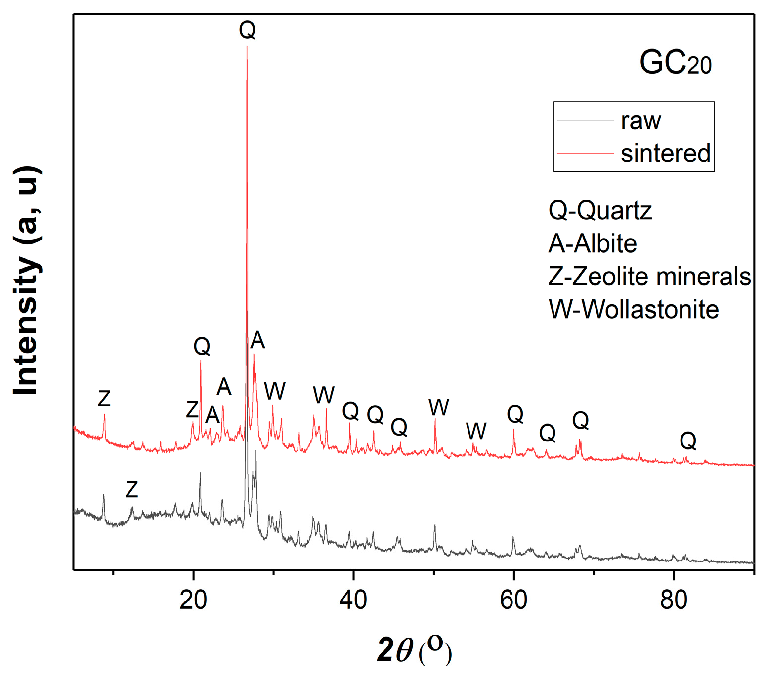
2.3.2. The Phase Composition (XRD) of the Raw and Sintered Samples

The crystalline-phase composition of all the GC samples in raw form and after sintering at 700 °C for 7 h was investigated by means of X-ray diffraction (XRD) analysis in order to determine if the crystallinity of the samples changed after the exposure to high temperatures during thermal treatment. XRD analysis was performed using an Ultima IV (Rigaku, Tokyo, Japan) diffractometer with curved graphite monochrome and a scintillation counter. The intensity of CuKα (λ = 1.54178 Å) radiation as an X-ray source was recorded in a 2θ range of 5–90° using a scanning step size of 0.02° and scan rate of 5°/min; for routine phase analysis, a voltage of 40 kV and power of 40 mA were required for measurements. The phase identification of the samples was performed using PDXL2 software (version 2.8.3.0.) and the ICDD database [27].

2.3.3. Leaching Tests of the Raw and Sintered Samples

In order to determine the potential of the studied samples for leaching dangerous concentrations of heavy metals into the environment, batch leaching tests according to the DIN 38414-S4 standard method [28] were performed. The testing of heavy metal leaching was conducted on the raw and sintered samples GC15 and GC20. The sintered samples were subjected to 10 thermal cycles at 750 °C, being heated for 80 h in total. The concentration levels of trace heavy metals were recorded by means of the ICP-OES method.
Dry samples with particles smaller than 1 mm in an amount of 5 g were put on a grate placed inside a glass vessel. Then, 50 mL of demineralized water was poured into each vessel, after which the obtained mixtures were placed in a shaker. The speed of rotation was set to 150 rpm and the shaking lasted 24 h continuously. The samples were then filtered through filter paper 4 times, after which they were additionally centrifuged for 10 min at a rate of 150 rpm. Eventually, liquid parts of the samples, i.e., eluates, were examined.
The examination of the obtained eluates consisted of measuring the pH values and heavy metal content. The obtained heavy metal concentrations measured in the eluate were compared with the maximum allowed values according to the valid Rulebook on the categories, testing and classification of waste (“Sl. Glasnik RS 56/2010”), as well as EN 12457/EN 16192: 2011, which applies in the Republic of Serbia to the disposal of nonreactive hazardous waste.

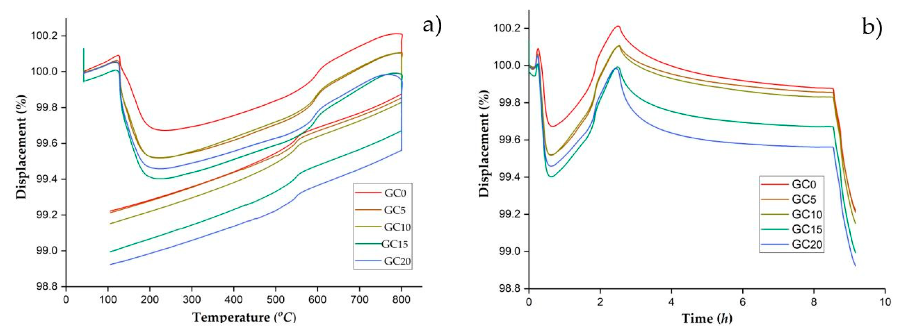
2.3.4. Dilatometry Analysis of Raw Samples

It is essential to examine the thermal expansion behavior of sealants or adhesive materials which operate at high temperatures. In order to avoid thermal stresses that might occur during thermal cycling, the coefficient of thermal expansion (CTE) of the samples must be matched with the CTE values of the other adjoining components. Otherwise, crack formation and damage to the joints will be caused.
The information on thermomechanical properties, i.e., the thermal expansion behavior of all GC samples was collected by employing dilatometry analysis. During this experiment, the linear dimensional change (expansion/shrinkage) of the GC sample was measured with a highly accurate displacement sensing system (TMA dilatometer, Setsys, SETARAM Instrumentation, Caluire, France). For the purpose of performing these tests, powdery GC samples were initially compacted at 200 MPa into small cylinders with a 6 mm diameter tool using a uniaxial press (Laboratory Hydraulic Press, 54/1114 Group Struson, Xiamen Tmax Battery Equipments Limited, Xiamen, China) so that solid samples were obtained. The measurements were taken from room temperature (RT) to 800 °C at a heating rate of 5 °C/min with a retention time of 6 h at 800 °C.

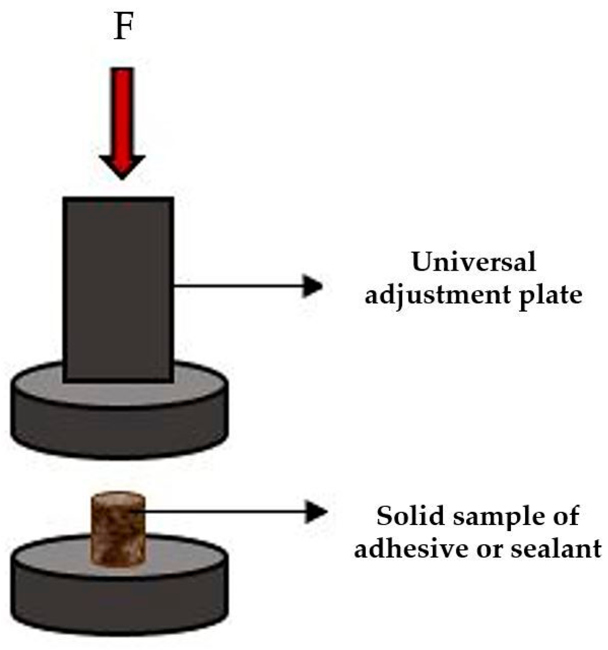
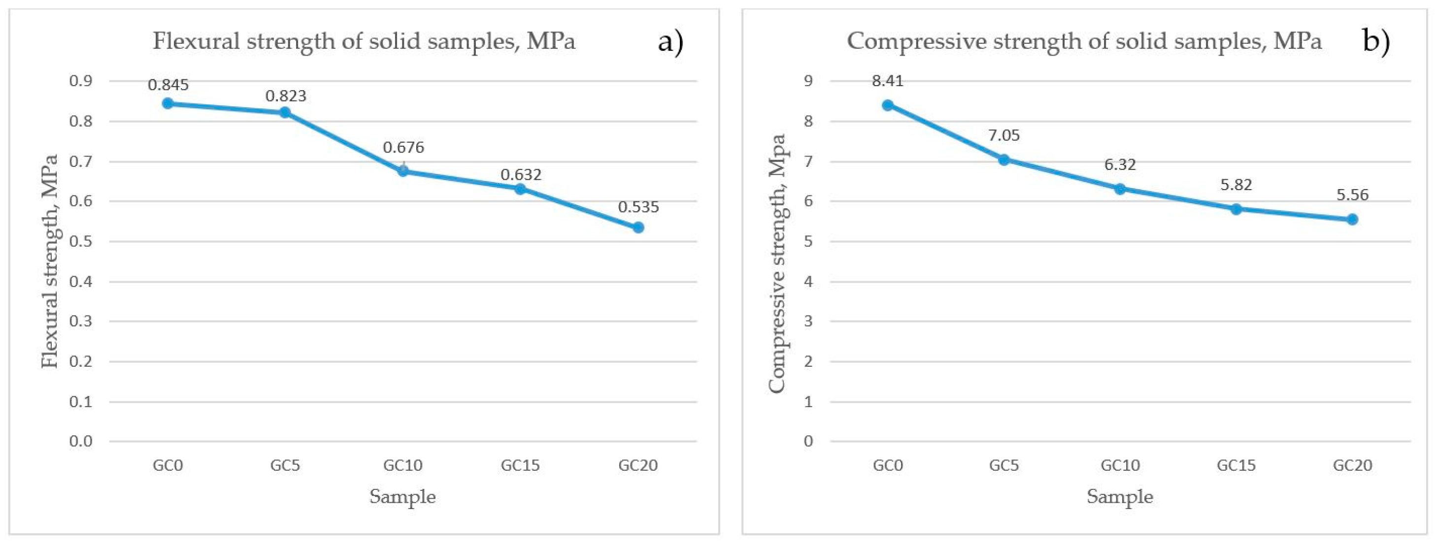
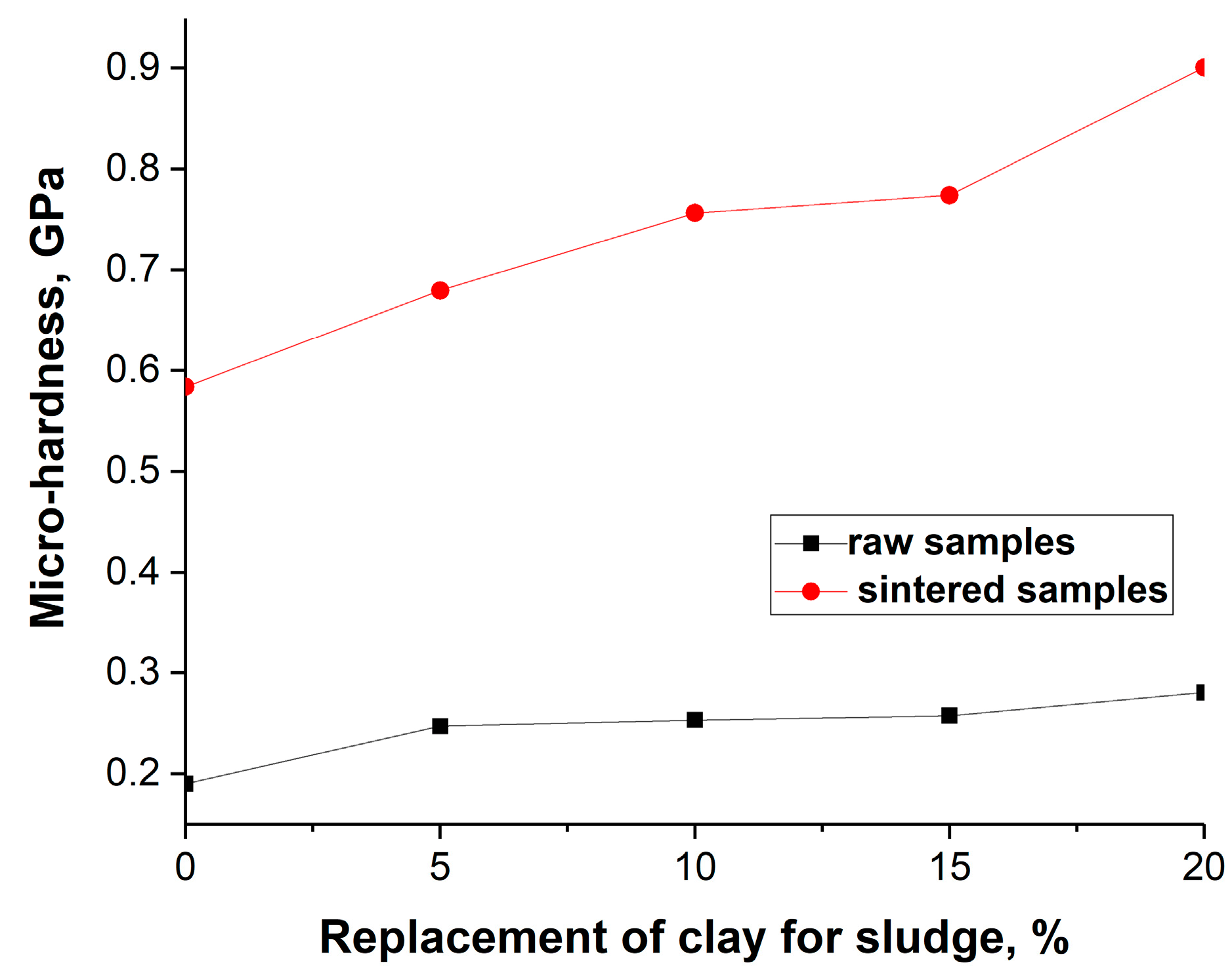
2.3.5. The Mechanical Properties of the Sintered Samples

The characterization of the mechanical properties consisted of flexural strength, fracture toughness (crushing strength), and microhardness determination. Measurements of flexural and compressive strength were conducted on solid samples obtained by pouring the GC samples in the form of viscous paste into molds of desired dimensions and heating at 800 °C.
The operating temperatures of the heating equipment in which the examined adhesives were to be applied did not exceed 400–500 °C; therefore, it was not necessary to set the sintering temperature to any higher than that. However, since these compositions were also examined for their application as sealants for IT-SOFCs that operate at temperatures between 500 °C and 800 °C, the sintering temperature was set to be 800 °C. Moreover, thermal stability tests were previously conducted on temperatures up to a maximum of 800 °C, so practically, it is unknown whether these materials would be stable at higher temperatures.
For the purpose of flexural strength (modulus of rupture) determination, cylindrical solid samples of all GC compositions with dimensions Φ5.5 mm × H30 mm were prepared and a three-point bending test method using a Universal Testing Machine (Model: Instron 1185, Instron, Boston, MA, USA) with a crosshead speed of 1 mm/min was performed in accordance with the Chinese national standard GB/T3001-2007 [29]. Cylindrical samples were initially air-dried at room temperature for 24 h and then heat-treated at 800 °C for 8 h prior to the measurements. The distance between the supports in the test was set to be 20 mm. For the calculation of flexural strength values (σ) of the samples, the following equation, Equation (1), was applied:
σf = (L*F)/(π R3),
where σf is the flexural strength of the sample (MPa); F is the flexural force leading to the sample failure (N); L is the distance of the supporting pin (<mm); and R is the radius of the cross section of the sample (mm).
Crushing-strength (fracture toughness) measurements were conducted on cylindrical solid samples of all GC compositions with dimensions of Φ6 mm × H6 mm. The test method using the Universal Testing Machine (Model: Instron 1185) with a speed of crosshead of 1 mm/min is presented in Figure 3. The samples were initially cured at ambient temperature (20 °C) for 24 h and then heated at 800 °C for 8 h before testing. For the calculation of crushing-strength values (σc), the following formula was used (Equation (2)):
σc = F/S,
where σc is the crushing strength of the sample (MPa); F is the maximum load at which the sample breaks apart (N); and S is the pressed area of the sample (mm2).
For the measurements of microhardness both, the raw and sintered GC samples were pressed at 200 MPa and prepared for the tests in the form of pellets (solid samples). All of them were cylindrically shaped with dimensions of Φ16 mm × H2 mm. Sintered solid samples were prepared by heating at 800 °C for 8 h. In order to obtain plane-parallel surfaces for the test, the obtained solid samples were polished employing SiC paper with a P2000 grain size. The indentation test method (Vickers hardness test) was applied for an evaluation of the microhardness of the solid samples. The experiments were carried out using a Buehler Micromet Microindentation Hardness Tester (Model Micromet 5101, Buehler, Lake County, United States). For each raw and sintered GC solid sample, three measurements were performed and average values were calculated. Since the raw solid samples were estimated to be very soft, a small load of 0.25 N was applied in the tests, while for the sintered samples, the load was set to be higher, 0.5 N. The time of indentation was 15 s.

2.4. The Performance of Materials for Potential Application as IT-SOFC Sealants

2.4.1. The Phase Composition (XRD) and Morphology (FESEM) of the Raw and Sintered Samples

Reactivity tests consisted of exposing all the GC samples to CO2 gas, one of the commonly used fuels in the operation of IT-SOFCs. In order to investigate potential undesirable chemical reactions and alterations that might occur between the gas and some of the sealant constituents in the common operating conditions of the fuel cell device, the characterization of the crystalline-phase composition (XRD)of all sintered samples before and after exposure to CO2 gas at 700 °C and morphology investigations (FESEM)of raw samples as well as samples sintered at 700 °C and exposed to CO2, were carried out. In this manner, it was possible to justify the applicability of the studied compositions in IT-SOFC systems and to secure the safe conduction of the following Open Circuit Voltage (OCV) test.
XRD analysis was performed according to the same procedure previously described in Section 2.3.2 of the paper. The surface morphology and microstructure of the polished cross-sections were determined with Field-Emission Scanning Electron Microscopy (FESEM) using the microscope model TESCAN VEGA TS 5130MM (TESCAN, Brno, Czech Republic). Prior to observation, the samples were precoated with a several-nanometers-thick layer of gold. The FESEM images were recorded at a magnification ×2.00 kx with an accelerating voltage of 20 kV.

2.4.2. Open Circuit Voltage (OCV) Test—Leakage Detection of a Single Laboratory Fuel Cell

For the purpose of the OCV (Open Circuit Voltage) test, which basically confirmed the functionality of IT-SOFC sealants in realistic working conditions, a sample of the basic composition (GC0) was deposited in slurry form on the edges of the electrolyte and the tube of the laboratory fuel cell in order to secure a gas-tight connection. Afterward, the sealed fuel cell device was heated in a chamber furnace in accordance with the curing protocol needed for the sealant to reach its full toughness and hardness (2 h of heating at each temperature: 90, 260, and 370 °C). This protocol applies to the commercial sealants used for this purpose, which is why it was implemented in this test as well.
Provided that the first single-cell test with sample GC0 ended successfully, further tests employing other samples (GC5, GC10, GC15, and GC) were performed.

3. Results and Discussion

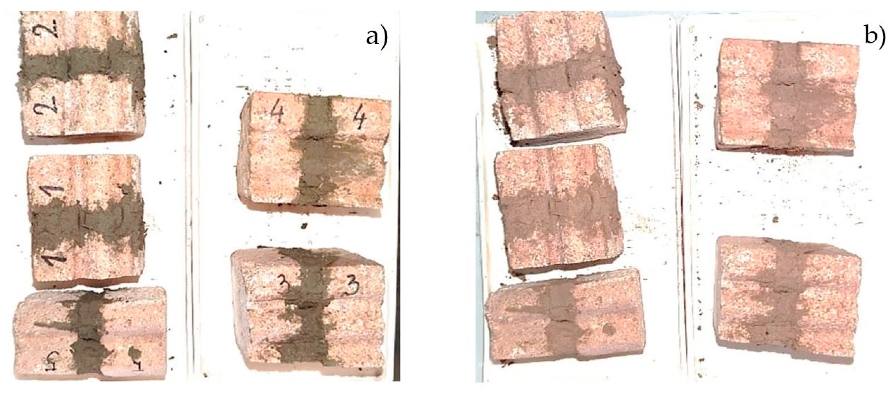
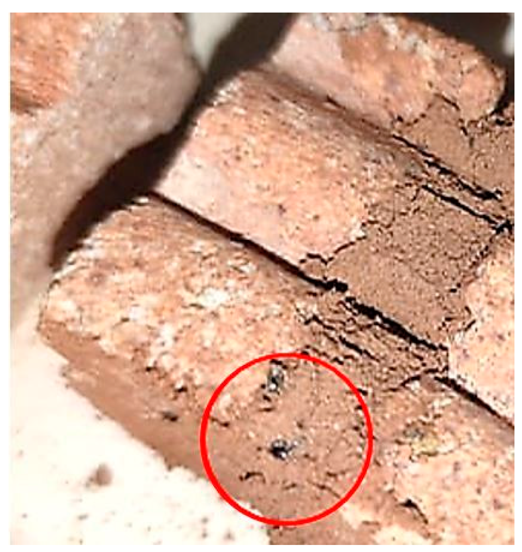
3.1. The Results of the Thermal Cycling Test of Ceramic Joint Specimens

After the completion of the thermal cycling test with a duration of over 100 h, it was found that all the prepared ceramic joint specimens withstood high temperatures without significant visible alterations, cracks, or breakage, as shown in Figure 4. After a detailed observation, it was assumed that all of them remained completely undamaged and the ceramic bricks remained well bonded. This test clearly indicated good thermal stability and reliability in all the GC samples at temperatures up to 800 °C with satisfactory bonding ability, which is mandatory for their application either as thermoresistant adhesives for heating-device connections or as sealants for IT-SOFCs. Accordingly, the studied samples were considered to be completely safe from the aspect of thermostability for further examination.
Nevertheless, on sample GC10 (Figure 5), some slightly larger waste sludge particles were clearly visible due to the darker color, which indicated that a sieving of the components was needed in order to obtain a more uniform, finer material and a homogenous mixture with fully defined characteristics. Moreover, this was especially important since the values of mechanical properties of adhesive and sealant materials tend to decrease with increasing particle size [30]. Moreover, the sealants for IT-SOFCs generally consist of microsized particles [31,32]. Therefore, prior to sample preparation, all the components in the GC compositions were additionally sieved through a 63 μm laboratory test sieve and further experiments were conducted with samples containing particles of a size below 63 μm.

3.2. Results of the Characterization of Raw and Sintered Samples

3.2.1. Results of the Chemical Composition of the Waste Sludge and Raw Samples

The results of chemical composition regarding heavy metal concentrations are presented in Table 1. According to “Standard Sl. Glasnik 56/2010” as well as EN 12457/EN 16192: 2011, which applies in the Republic of Serbia, in the investigated waste sludge sample, the content of certain heavy metal ions exceeded the maximum values allowed for the classification of waste as nonhazardous; therefore, it can be classified as hazardous waste.
However, based on guidelines prescribed by the Rulebook on restrictions and prohibitions on the production, placing on the market and use of chemicals as well as by the Rulebook on the categories, testing and classification of waste, restrictions on the utilization of raw waste materials as an additive for industrial products in the energy industry have not been defined yet on the basis of the concentration of heavy metals.
The waste sludge chemical composition in terms of the oxide content is shown in Table 2. The obtained oxide proportion confirms that the waste sludge material was of aluminosilicate composition with a non-negligible admixture of iron oxides and a rather large share of volatile organic matter. Moreover, alkali oxides are present in a great proportion, especially sodium oxides.
As can be observed from the results of the chemical composition determination of all the GC samples, given in Table 3, the content of Cu ions in the samples GC15 and GC20 exceeded the maximum concentration limits allowed for the classification of waste as nonhazardous according to the Rulebook on categories, testing and classification of waste (“Standard Sl. Glasnik 56/2010”), as well as EN 12457/EN 16192: 2011, which applies in the Republic of Serbia to the disposal of nonreactive hazardous waste. However, the Cu content of GC15 was practically within acceptable limits if we consider the permissible error of measurements (±2.5%).
Therefore, only the sample labeled as GC20 did not meet the mentioned criteria for heavy metal content and is not ecologically acceptable to be used for commercial purposes. The maximum percentage of the clay-for-sludge replacement that can be achieved without affecting the stringent requirements concerning heavy metal content (in this case, Cu) in the composition is up to 15%. Therefore, the sample with the highest waste sludge content that satisfied the mentioned criteria and the most promising candidate for application as a ceramic adhesive or IT-SOFC sealant is GC15. However, additional tests are required to determine the leachability of certain heavy metals in the samples (these results will be presented in Section 3.2.3). If these measurements confirm no dangerous leaching values, these compositions could also be considered acceptable from an environmental point of view.

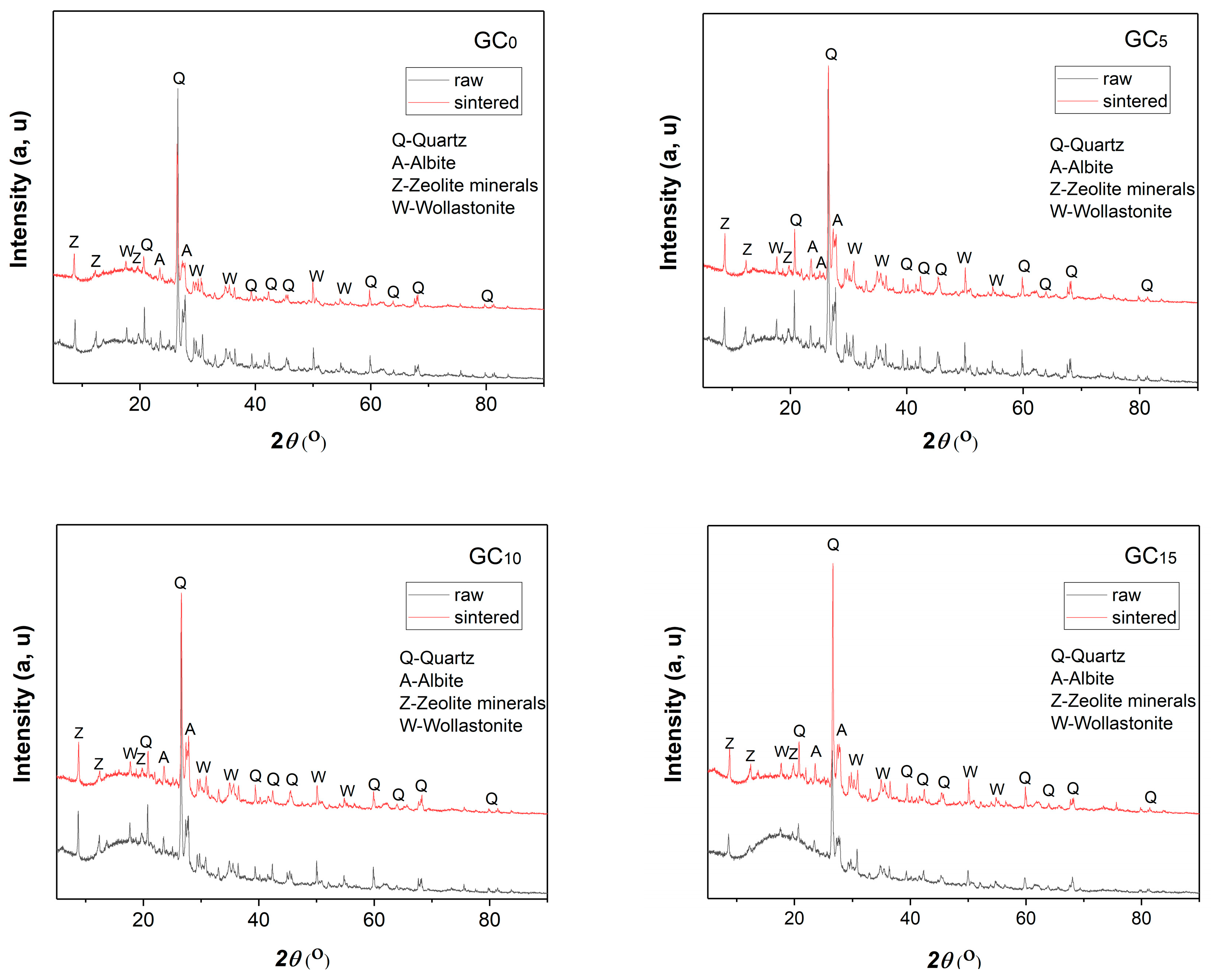
3.2.2. Results of the XRD Analysis of the Raw and Sintered Samples

For a determination of the crystal-phase composition of all the GC samples in raw form and after sintering at 700 °C for 7 h, XRD analysis was carried out, and the obtained diffractograms are displayed in Figure 6.
The mineralogical composition of the samples was determined by identifying the crystal phases of the following clay minerals: quartz, as the most abundant; then albite; minerals from the group of zeolites; and wollastonite. It was observed that the identified mineral phases had high structural order, which is indicated by sharp and high-intensity peaks. The slightly higher background present in the angular range of 5–30° 2θ of the raw samples’ diffractograms most likely represents a slightly higher content of organic and amorphous phase in these samples. Moreover, narrow, high-intensity, and clearly defined peaks of quartz and zeolite minerals in the raw samples indicate a good structural arrangement of these phases, while wollastonite’s peaks have some lower intensities, which most likely indicate the content of this phase is a little lower. The structural arrangements of the identified minerals remained unchanged during thermal treatment at 700 °C; also, new phases were not identified. However, considering the obvious alignment of the baseline in the diagrams, it can be said that thermal treatment led to the disappearance of the organic phase since a better structural arrangement in the angular range of 5–30° 2θ occurred in the sintered samples.

3.2.3. Results of the Leaching Tests of the Raw and Sintered Samples

From the obtained results of ICP analysis in Table 4, it can be observed that the concentrations of all examined elements in the samples GC15 and GC20 were lowered after being thermally treated at 750 °C for 80 h, except for Cr. The increased mobility of Cr after the sintering process can be explained by the fact that, unlike Hg and Cd, Cr is considered nonvolatile and tends to reside in the material after being sintered at certain temperatures [33]. Moreover, some studies have reported that heat treatment might promote the Cr leaching behavior of samples, which, therefore, might exhibit relatively higher Cr leaching accumulation after exposure to high temperatures up to 750 °C [34].
However, the values of leached Cr do not practically pass the limitation if we consider a permissible measurement error of ±2.5%. Also, the leached concentrations of As for the raw samples exceed the maximum allowed concentration values for the classification of waste as nonhazardous, according to the Rulebook on Categories, Testing and Classification of Waste (“Standard Sl. Glasnik 56/2010”), as well as EN 12457/EN 16192: 2011, which applies in the Republic of Serbia to the disposal of nonreactive hazardous waste. Nevertheless, after exposure to high temperatures, which are inevitable in the operating environment of refractory ceramic adhesives and IT-SOFC sealants, these concentrations decreased to acceptable values below the prescribed limits.
In addition to the concentrations of all the leached elements for the examined GC samples, the pH values measured before and after the leaching tests of the examined GC samples are given in Table 4.

3.2.4. Results of the Dilatometry Analysis of the Raw Samples

The dilatometry analysis curves of percentage linear changes in all the compacted GC samples from RT to 800 °C are presented as a function of temperature in Figure 7a and as a function of heating time in Figure 7b. Shrinkage and expansion occur sequentially with the increase in temperature from RT to 800 °C, after which shrinkage can be observed due to prolonged heating at 800 °C.
The dilatometry plot clearly shows that waste percentage addition in the compositions slightly reduced the temperature corresponding to the onset of shrinkage. However, each GC sample, while being heat-treated at 800 °C for 8 h, exhibited very little linear dimensional change, where the shrinkage or expansion was in the order of magnitude of only around 0.5%. This can be explained by the above-discussed phase composition of the GC samples. Namely, according to the performed XRD analysis, several crystal phases of clay minerals were identified: quartz, as the most abundant, but also albite, wollastonite, and zeolite minerals. As is commonly known, one of the main characteristics of quartz from the thermal point of view is its low thermal expansion coefficient (CTE = 5 × 10⁻⁷/°C), i.e., exceptional thermal stability at temperatures up to 1100 °C [35]. Wollastonite is similar: it has a very low expansion rate (CTE = 7 × 10⁻⁶/°C) and good thermal shock resistance after heating up to 800 °C [36]. Also, pure albite is reported to be thermally stable below a temperature of 1000 °C [37]. Moreover, temperatures at which structural changes in most zeolite minerals take place are at 800 °C or above [38].

3.2.5. Results of the Mechanical Properties of the Sintered Samples

As can be seen from Figure 8, the lowest values of flexural and compressive strength were recorded for the sample with the greatest share of incorporated waste sludge, GC20. Moreover, it can be observed that both the flexural and compressive strength of the solid samples decreased uniformly at the higher waste sludge content. Indeed, the reduction in the flexural and compressive strength of the solid samples could be possibly related to the lower final density of the samples along with the higher concurrent matrix microcracking at the higher magnitude of waste sludge particles.
Expectedly, the results of the Vickers hardness test show that the sintered samples displayed much higher values compared to the raw ones. The lower Vickers microhardness (HV) of the raw samples could be related to their lower density. Moreover, the HV of the samples improved in concordance with the increase in the waste content share in the samples, which indicates that waste addition had a positive impact on the microhardness of the obtained samples in this case. The HV values for both the raw and sintered solid GC samples are presented in Table 5. The unit of hardness given by the test is known as the Vickers Pyramid Number (HV). A graphical representation of the obtained values expressed in Si units (GPa) is shown in Figure 9.
Even though there are no particular required normative values which have been suggested in previous research for the mechanical properties of high-temperature industrial adhesives or IT-SOFC sealant materials, it is clear that certain mechanical capabilities must be provided for the sake of preventing gas leakages and the adhesion of the device components during operation, as well as for surviving harsh conditions and stresses that might occur at the high operating temperatures of these devices. Basically, these materials should be able to provide satisfying robustness and reliability to the overall system.
According to the extensive literature review, it can be noticed that the compressive and flexural strength as well as the microhardness of the studied samples were significantly lower than those reported in the literature for different SOFC ceramic sealant materials [31,32,39,40,41]. Therefore, the presently studied materials would probably not be such good candidates for application in SOFC technology, except if some additives were added to improve these properties.
However, for the purpose of bonding, i.e., filling the gaps between the components of heating devices, there are no such strict requirements concerning the mechanical properties of the material since it is usually applied in a very thick layer, which can retain the integrity and withstand potential thermal stresses. Moreover, considering that the previously conducted thermal cycling test was completed without damage to or the disintegration of the prepared ceramic joint specimens, these obtained results of flexural and compressive strength might be considered satisfactory for the application of the studied materials as high-temperature ceramic adhesives for providing good connections in the heating equipment structure.
Being in accordance with the previously confirmed excellent thermophysical behavior, the obtained values of the overall mechanical characteristics of all the examined GC samples were found to be sufficient for application as efficient ceramic adhesives in high-temperature industrial systems, such as heating devices. The results of all the tested mechanical features corroborated the established thermal and chemical stability and favorable physical performances, and indeed, they may assure that these materials would provide satisfying robustness and reliability in a high-temperature system (e.g., heating device) in which they are applied as adhesives.

3.3. Results of Material Performance for Potential Application as IT-SOFC Sealants

3.3.1. Results of the XRD and FESEM Analyses of the Raw and Sintered Samples

In order to verify their chemical stability in contact with IT-SOFC fuel at operating temperatures, the raw and sintered GC samples were analyzed before and after exposure to CO2 gas at 700 °C in terms of the crystal-phase composition (XRD) and microstructural characteristics (FESEM). The resulting XRD diagrams and FESEM images are given in Figure 10.
From the XRD results, it can be noticed that all the sintered GC samples did not exhibit significant changes in crystal-phase composition after exposure to the CO2 environment. Identical phases with rather narrow and sharp peaks were detected. However, an additional loss of amorphous phase and better structural arrangement in the angular range of 5–30° 2θ were observed in the sintered samples, especially GC0 and GC10, after the reactivity test’s completion.
According to the SEM images presented in Figure 10, there was no evident, noticeable difference in the microstructure of the raw samples and the samples submitted to the reactivity test. Agglomerates of about 20–50 μm in diameter and irregularly shaped grains of about 5 μm in diameter were dominant in the structure of the samples exposed to gas CO2 at 700 °C. In most samples, the presence of microporosity was observed after conducting the tests. Despite the existence of visible pores, these samples showed satisfactory strength and compactness, which means that the porosity was superficial and that the grains were actually tightly bound within the sample.

3.3.2. Results of the Open Circuit Voltage (OCV) Test—Leakage Detection of a Single Laboratory Fuel Cell

A single laboratory fuel cell with the applied sealant sample before and after the performed OCV test is shown in Figure 11. As can be clearly noticed, the sealant did not retain structural integrity after the treatment since large cracks occurred and the sample completely disintegrated. Therefore, hermetic sealing between the ceramic components of the cell, i.e., the electrolyte and the fuel tube, cannot be provided.
This experimental failure indicated that the studied glass–ceramic material is not suitable for very complex and precision-demanding IT-SOFC technology. Also, this statement is in accordance with the previous assumption that the obtained results of mechanical properties of these samples are insufficient for this application. However, certain modifications, in view of the procedure of preparation or the sharing and selection of components, might result in achieving rugged and stable joints between the ceramic parts of the fuel cell. Therefore, the major future aspects of this research should be aimed at finding a proper solution for the application of such modified waste-containing materials as sealants in IT-SOFC technology and thus expanding their usability to this industry as well.

4. Conclusions

Novel, eco-friendly, cost-effective, and highly efficient glass–ceramic materials with different partial implementations of aluminosilicate-based waste sludge were prepared and investigated for potential application in advanced technology solutions: as high-temperature ceramic adhesives and as IT-SOFC sealants. The effects of the waste addition on the composition of samples were studied in terms of reliability, thermal and chemical stability, as well as physical and mechanical properties.
The excellent performance of the obtained samples in joining bricks after the completion of the thermal cycling test initially made them promising candidates for high-temperature applications considering good thermal stability and bonding ability. Via a leaching test, the samples were confirmed as ecologically acceptable with values of heavy metal concentrations below those legally allowed. The physical–mechanical properties of the samples were found to be sufficient for their application as industrial ceramic adhesives since satisfying robustness and reliability in the system can be provided, as already confirmed by a previously performed thermal cycling test. The successfully conducted reactivity test followed by XRD and SEM characterizations corroborated the absence of potential undesirable chemical reactions and alterations that might occur between the gas and some of the potential sealant constituents at common temperatures of fuel cell operation. However, regarding the failure of the OCV test and the inability to maintain structural integrity after being applied in the laboratory SOFC device in operation at 700 °C, it was found that these materials are not applicable as sealants for IT-SOFC technology. Despite this, there is indeed great potential for these materials to become effective and reliable for this purpose as well, after some modification concerning the composition and preparation methodology, which could be the major focus of further research in this field.

Author Contributions

Conceptualization, M.S. and N.N.; methodology, M.K.; validation, J.G.; investigation, M.G., M.Ž. and F.B.; writing—original draft preparation, N.N.; writing—review and editing, M.S.; visualization, N.N.; supervision, M.K.; project administration, M.S.; All authors have read and agreed to the published version of the manuscript.

Funding

This research received no external funding.

Institutional Review Board Statement

Not applicable.

Informed Consent Statement

Not applicable.

Data Availability Statement

Not applicable.

Acknowledgments

These investigations were supported by the Ministry of Science, Technological Development and Innovation of the Republic of Serbia (Contract numbers 451-03-47/2023-01/200017) through the realization of research themes 1702303 and 1702305. Thanks to the following people: Smilja Marković, Institute for Testing of Materials-IMS Institute, Bulevar vojvode Mišića 43, 11040, Belgrade, Serbia for the dilatometric measurements, and Ivana Cvijović-Alagić, Institute of Nuclear Sciences “Vinča”-National Institute of the Republic of Serbia, University of Belgrade, 22-24 Mike Petrovića Alasa, 11351, Belgrade, Serbia for the microhardness measurements.

Conflicts of Interest

The authors declare no conflict of interest.

References

  1. Nasrollahi, Z.; Hashemi, M.S.; Bameri, S.; Mohamad Taghvaee, V. Environmental pollution, economic growth, population, industrialization, and technology in weak and strong sustainability: Using STIRPAT model. Environ. Dev. Sustain. 2020, 22, 1105–1122. [Google Scholar] [CrossRef]
  2. Opoku, E.E.O.; Aluko, O.A. Heterogeneous effects of industrialization on the environment: Evidence from panel quantile regression. Struct. Chang. Econ. Dyn. 2021, 59, 174–184. [Google Scholar] [CrossRef]
  3. Usman, M.; Balsalobre-Lorente, D. Environmental concern in the era of industrialization: Can financial development, renewable energy and natural resources alleviate some load? Energy Policy 2022, 162, 112780. [Google Scholar] [CrossRef]
  4. Das, S.; Lee, S.H.; Kumar, P.; Kim, K.H.; Lee, S.S.; Bhattacharya, S.S. Solid waste management: Scope and the challenge of sustainability. J. Clean. Prod. 2019, 228, 658–678. [Google Scholar] [CrossRef]
  5. Abouelela, A.R.; Mussa, A.A.; Talhami, M.; Das, P.; Hawari, A.H. Industrial sludge valorization and decontamination via lipid extraction and heavy metals removal using low-cost protic ionic liquid. Sci. Total Environ. 2022, 835, 155451. [Google Scholar] [CrossRef]
  6. Basu, D.; Pal, P.; Prakash, A. Utilization of waste sludge in cementitious matrix: A feasibility study. Mater. Today Proc. 2022, 65, 1375–1381. [Google Scholar] [CrossRef]
  7. Gherghel, A.; Teodosiu, C.; De Gisi, S. A review on wastewater sludge valorisation and its challenges in the context of circular economy. J. Clean. Prod. 2019, 10, 244–263. [Google Scholar] [CrossRef]
  8. Patil, R.A.; Ramakrishna, S. A comprehensive analysis of e-waste legislation worldwide. Environ. Sci. Pollut. Res. 2020, 27, 14412–14431. [Google Scholar] [CrossRef] [PubMed]
  9. Bekezhanov, D.; Omirali, A.; Aitimov, B.; Nurmukhankyzy, D.; Zhumagulov, T. Environmental and legal framework for regulating consumer and industrial waste management. J. Environ. Manag. Tour. 2020, 11, 186–193. [Google Scholar] [CrossRef]
  10. Neves, S.A.; Marques, A.C. Drivers and barriers in the transition from a linear economy to a circular economy. J. Clean. Prod. 2022, 341, 130865. [Google Scholar] [CrossRef]
  11. Meath, C.; Karlovšek, J.; Navarrete, C.; Eales, M.; Hastings, P. Co-designing a multi-level platform for industry level transition to circular economy principles: A case study of the infrastructure CoLab. J. Clean. Prod. 2022, 347, 131080. [Google Scholar] [CrossRef]
  12. Charef, R.; Lu, W.; Hall, D. The transition to the circular economy of the construction industry: Insights into sustainable approaches to improve the understanding. J. Clean. Prod. 2022, 364, 132421. [Google Scholar] [CrossRef]
  13. Nguyen, M.D.; Thomas, M.; Surapaneni, A.; Moon, E.M.; Milne, N.A. Beneficial reuse of water treatment sludge in the context of circular economy. Environ. Technol. Innov. 2022, 13, 102651. [Google Scholar] [CrossRef]
  14. Gomes, S.D.C.; Zhou, J.L.; Li, W.; Long, G. Progress in manufacture and properties of construction materials incorporating water treatment sludge: A review. Resour. Conserv. Recycl. 2019, 145, 148–159. [Google Scholar] [CrossRef]
  15. Limami, H.; Manssouri, I.; Cherkaoui, K.; Khaldoun, A. Recycled wastewater treatment plant sludge as a construction material additive to ecological lightweight earth bricks. Clean. Eng. Technol. 2021, 2, 100050. [Google Scholar] [CrossRef]
  16. Heniegal, A.M.; Ramadan, M.A.; Naguib, A.; Agwa, I.S. Study on properties of clay brick incorporating sludge of water treatment plant and agriculture waste. Case Stud. Constr. Mater. 2020, 13, e00397. [Google Scholar] [CrossRef]
  17. Meda, S.R.; Sharma, S.K.; Tyagi, G.D. Utilization of waste sludge as a construction material—A review. Mater. Today Proc. 2021, 46, 4195–4202. [Google Scholar] [CrossRef]
  18. Pradel, M.; Aissani, L. Environmental impacts of phosphorus recovery from a “product” Life Cycle Assessment perspective: Allocating burdens of wastewater treatment in the production of sludge-based phosphate fertilizers. Sci. Total Environ. 2019, 656, 55–69. [Google Scholar] [CrossRef]
  19. Chen, Y.H.; Ngo, T.N.L.T.; Chiang, K.Y. Enhanced hydrogen production in co-gasification of sewage sludge and industrial wastewater sludge by a pilot-scale fluidized bed gasifier. Int. J. Hydrog. Energy 2021, 46, 14083–14095. [Google Scholar] [CrossRef]
  20. Kamyab, H.; Yuzir, A.; Ashokkumar, V.; Hosseini, S.E.; Balasubramanian, B.; Kirpichnikova, I. Review of the application of gasification and combustion technology and waste-to-energy technologies in sewage sludge treatment. Fuel 2022, 316, 123199. [Google Scholar] [CrossRef]
  21. Nkuna, S.G.; Olwal, T.O.; Chowdhury, S.D. Assessment of thermochemical technologies for wastewater sludge-to-energy: An advance MCDM model. Clean. Eng. Technol. 2022, 9, 100519. [Google Scholar] [CrossRef]
  22. Available online: https://www.industryarc.com/Research/High-Temperature-Adhesives-Sealants-Market-Research-502948 (accessed on 25 May 2023).
  23. Wen, T.L.; Wang, D.; Chen, M.; Tu, H.; Lu, Z.; Zhang, Z.; Huang, W. Material research for planar SOFC stack. Solid State Ion. 2002, 148, 513–519. [Google Scholar] [CrossRef]
  24. Fergus, J.W. Sealants for solid oxide fuel cells. J. Power Sources 2005, 147, 46–57. [Google Scholar] [CrossRef]
  25. Zhang, J.; Luo, R.; Jiang, M.; Xiang, Q.; Li, J. The preparation and performance of a novel room-temperature-cured heat-resistant adhesive for ceramic bonding. Mater. Sci. Eng. A 2011, 528, 2952–2959. [Google Scholar] [CrossRef]
  26. Wang, M.; Song, Q.; Gu, Y.; Wu, C.; Liu, J.; Zhou, X.; Du, M. Multiple high-temperature resistant phases modified phosphate-based adhesive for engineering ceramic connection in extreme environment. Ceram. Int. 2019, 45, 516–521. [Google Scholar] [CrossRef]
  27. Tokyo Rigaku Corporation. PDXL Integrated X-ray Powder Diffraction Software; Rigaku Corporation: Tokyo, Japan, 2011. [Google Scholar]
  28. Qi, Y.; Szendrak, D.; Yuen, R.T.W.; Hoadley, A.F.; Mudd, G. Application of sludge dewatered products to soil and its effects on the leaching behaviour of heavy metals. J. Chem. Eng. 2011, 166, 586–595. [Google Scholar] [CrossRef]
  29. Chen, Y.; Wang, X.; Yu, C.; Ding, J.; Deng, C.; Zhu, H. Properties of inorganic high-temperature adhesive for high-temperature furnace connection. Ceram. Int. 2019, 45, 8684–8689. [Google Scholar] [CrossRef]
  30. Siviour, C.R.; Gifford, M.J.; Walley, S.M.; Proud, W.G.; Field, J.E. Particle size effects on the mechanical properties of a polymer bonded explosive. J. Mater. Sci. 2004, 39, 1255–1258. [Google Scholar] [CrossRef]
  31. Rezaei, N.; Ghatee, M. Barium-calcium aluminosilicate glass/mica composite seals for intermediate solid oxide fuel cells. Ceram. Int. 2021, 47, 21679–21687. [Google Scholar] [CrossRef]
  32. Hasanabadi, M.F.; Malzbender, J.; Groß-Barsnick, S.M.; Abdoli, H.; Kokabi, A.H.; Faghihi-Sani, M.A. Micro-scale evolution of mechanical properties of glass-ceramic sealant for solid oxide fuel/electrolysis cells. Ceram. Int. 2021, 47, 3884–3891. [Google Scholar] [CrossRef]
  33. Latosińska, J.; Czapik, P. The ecological risk assessment and the chemical speciation of heavy metals in ash after the incineration of municipal sewage sludge. Sustainability 2020, 12, 6517. [Google Scholar] [CrossRef]
  34. Zhang, S.; Zhang, Y.; Wu, S.; Zhao, Z.; Wu, Y. Long-term leaching mechanism of chromium-containing slag after vitrification and heat treatment. Ceram. Int. 2022, 48, 13366–13378. [Google Scholar] [CrossRef]
  35. Available online: https://www.qsiquartz.com/thermal-properties-fused-quartz/ (accessed on 16 June 2023).
  36. Zilles, J.U. Wollastonites. In Fillers for Polymer Applications; Polymers and Polymeric Composites: A Reference Series; Rothon, R., Ed.; Springer: Berlin/Heidelberg, Germany, 2017; Volume 489, pp. 203–230. [Google Scholar] [CrossRef]
  37. Feng, D.; Provis, J.L.; Jannie, S.J.; van Deventer, J.S. Thermal activation of albite for the synthesis of one-part mix geopolymers. J. Am. Ceram. Soc. 2012, 95, 565–572. [Google Scholar] [CrossRef]
  38. Cruciani, G. Zeolites upon heating: Factors governing their thermal stability and structural changes. J. Phys. Chem. Solids 2006, 67, 1973–1994. [Google Scholar] [CrossRef]
  39. Rodríguez-López, S.; Wei, J.; Laurenti, K.C.; Mathias, I.; Justo, V.M.; Serbena, F.C.; Baudin, C.; Malzbenger, J.; Pascual, M.J. Mechanical properties of solid oxide fuel cell glass-ceramic sealants in the system BaO/SrO-MgO-B2O3-SiO2. Ceram. Soc. 2017, 37, 3579. [Google Scholar] [CrossRef]
  40. Heydari, F.; Maghsoudipour, A.; Hamnabard, Z.; Farhangdoust, S. Mechanical properties and microstructure characterization of zirconia nanoparticles glass composites for SOFC sealant. Mater. Sci. Eng. A 2012, 552, 119–124. [Google Scholar] [CrossRef]
  41. Lin, C.K.; Chen, J.Y.; Tian, J.W.; Chiang, L.K.; Wu, S.H. Joint strength of a solid oxide fuel cell glass-ceramic sealant with metallic interconnect. J. Power Sources 2012, 205, 307–317. [Google Scholar] [CrossRef]
Figure 1. Sample of waste sludge obtained from the wastewater treatment plants.
Applsci 13 09044 g001
Figure 2. Adhesive and sealant samples with different shares of waste sludge addition (GC0, GC5, GC10, GC15, and GC20).
Applsci 13 09044 g002
Figure 3. Schematic diagram of the compressive strength testing.
Applsci 13 09044 g003
Figure 4. Ceramic joint specimens before (a) and after (b) thermal cycle of 100 h at temperatures in the range of 200–800 °C.
Applsci 13 09044 g004
Figure 5. Sample GC10 applied between ceramic bricks after thermal cycling, with larger waste particles on the surface indicating insufficient homogeneity.
Applsci 13 09044 g005
Figure 6. XRD diffractograms of all GC samples in raw form and after sintering at 700 °C: GC0, GC5, GC10, GC15, and GC20, respectively.
Applsci 13 09044 g006aApplsci 13 09044 g006b
Figure 7. Dilatometric curves of percentage linear changes in all GC samples heated from RT to 800 °C as a function of temperature (a) and as a function of heating time (b).
Applsci 13 09044 g007
Figure 8. Graphical representation of values of flexural (a) and compressive (b) strength of solid GC samples.
Applsci 13 09044 g008
Figure 9. Microhardness of raw and sintered glass–ceramic samples.
Applsci 13 09044 g009
Figure 10. XRD diffractograms of all sintered samples (GC0, GC5, GC10, GC15, and GC20, respectively) before and after exposure to CO2 gas at 700 °C (left) and FESEM images of raw samples (a) and samples sintered at 700 °C and exposed to CO2 (b), simultaneously (right).
Applsci 13 09044 g010aApplsci 13 09044 g010b
Figure 11. Laboratory fuel cell before (a) and after (b) OCV testing.
Applsci 13 09044 g011
Table 1. Chemical composition of the waste sludge—content of heavy metals.
Concentrations, mg/kg, in Waste Sludge
ParameterLP SludgePE SludgeLP+PE Sludge (1:1)Ref. Values
Hg<0.15<0.15<0.150.2 */2 **
Sb0.8585.543.1750.7 */5 **
Se<0.22.5<1.350.5 */7 **
Cu20.520501035.2550 */100 **
Zn37175.5106.2550 */200 **
Ni81869710 */40 **
Cd2.564.251 */5 **
Pb103723.510 */50 **
As2.5<0.5<1.52 */25 **
Cr8221510 */70 **
Mn60048552727.5-
Tl<0.052.5<1.275-
Fe18,75013,25016,000-
Co3.523301166.75-
According to “Standard Sl. Glasnik 56/2010”: * values refer to the disposal of nonreactive hazardous waste in landfills for nonhazardous waste in fields that are not used for disposal of biodegradable waste. ** values refer to disposal in landfills for hazardous waste.
Table 2. Constituents in the composition of waste sludge—oxide content.
Content of Oxides (wt, %) in Waste Sludge
ComponentAl2O3SiO2Fe2O3Na2OK2OCaOMgOSO3P2O5
LP sludge2.681.9714.353.562.6090.1670.1330.0952.255
PE sludge16.6710.7811.0119.293.7923.4550.6970.8568.57
LP+PE sludge (1:1)9.6756.37557.6811.4253.2011.8110.4150.4755.413
Table 3. Analysis results of heavy metal content in adhesive and sealant samples containing waste.
Concentration, mg/kg, in Adhesive and Sealant Sample Composition
ParameterGC5GC10GC15GC20Ref. Values
Hg<0.15<0.15<0.15<0.150.2 */2 **
Sb0.70381.40762.11142.81520.7 */5 **
Se<0.022<0.044<0.066<0.0880.5 */7 **
Cu16.874633.749250.623867.498450 */100 **
Zn1.73193.46385.19576.927650 */200 **
Ni1.58113.16224.74336.324410 */40 **
Cd0.06930.13860.20790.27721 */5 **
Pb0.3830.76601.1491.53210 */50 **
As<0.0245<0.0490<0.0735<0.0982 */25 **
Cr0.24450.48900.73350.97810 */70 **
Mn44.458288.9164133.3746177.8328-
Tl<0.0245<0.0490<0.0735<0.098-
Fe260.8521.6000782.41043.2-
Co19.034338.068657.102976.1372-
According to “Standard Sl. Glasnik 56/2010”: * values refer to the disposal of nonreactive hazardous waste in landfills for nonhazardous waste in fields that are not used for disposal of biodegradable waste. ** values refer to disposal in landfills for hazardous waste.
Table 4. Results of leaching test for raw and sintered samples GC15 and GC20.
Concentration, mg/kg, in Adhesive and Sealant Samples’ Composition
ParameterGC15 RawGC20 RawGC15 SintGC20 SintRef. Values
pH before test10.9110.9211.7111.52-
pH after test10.6710.6710.910.39-
Al132.4104.1257.1120.1-
As3.2823.290.024520.21542 */25 **
Ca64.9658.45769.1616.1-
Cd0.0080390.0083721UDVUDV1 */5 **-
Co0.18950.24010.0082660.02789-
Cr0.098190.108110.1110.2510 */70 **
Cu2.3952.7610.40030.738150 */100 **
Fe12.1813.630.39472.701-
Hg0.0015940.0000530.0006610.0002230.2 */2 **
K187.3198.262.9292.2-
Mg17.6616.4434.2535.56-
Mn0.40340.49250.0097290.08828-
Mo1.892.6592.863.45210 */30 **-
Na2577026420693.12532-
Ni0.18750.1983UDV0.0123310 */40 **
P151418020.404752.39
Pb0.96081.2650.079410.253210 */50 **
S792.7839.4299.7323.3
Se0.1920.26170.0096270.013740.5 */7 **
V1.2481.2420.99371.106
Zn0.19890.3054UDV0.0229250 */200 **
1UDV- under detection values. According to “Standard Sl. Glasnik 56/2010”: * values refer to the disposal of nonreactive hazardous waste in landfills for nonhazardous waste in fields that are not used for disposal of biodegradable waste. ** values refer to the disposal in landfills for hazardous waste.
Table 5. Microhardness of samples before and after thermal treatment for 8 h at 800 °C.
SampleNo.HV0.025, HV[HV0.025]sr, HVSampleNo.HV0.05, HV[HV0.05]sr, HV
GC0
raw
119.519.4GC0
sintered
156.859.57
219.6259.7
319.1362.2
GC5
raw
125.225.23GC5
sintered
166.669.37
225.3271.9
325.2369.6
GC10
raw
126.225.83GC10
sintered
177.077.2
225.8279.3
325.5375.3
GC15
raw
125.826.27GC15
sintered
17779.0
226.8279.3
326.2380.7
GC20
raw
128.428.63GC20
sintered
191.791.9
228.8290.0
328.7394.0
Disclaimer/Publisher’s Note: The statements, opinions and data contained in all publications are solely those of the individual author(s) and contributor(s) and not of MDPI and/or the editor(s). MDPI and/or the editor(s) disclaim responsibility for any injury to people or property resulting from any ideas, methods, instructions or products referred to in the content.

