Article

Experimental Investigation of Precast Rocking Walls Incorporating Tension-Compression and Shear Steel Energy Dissipaters

1
China-Pakistan Belt and Road Joint Laboratory on Smart Disaster Prevention of Major Infrastructures, Southeast University, Nanjing 211189, China
2
School of Civil Engineering, Southeast University, Nanjing 211189, China
3
College of Civil Engineering, Nanjing Forestry University, Nanjing 210037, China
*
Author to whom correspondence should be addressed.
Appl. Sci. 2023, 13(15), 8817; https://doi.org/10.3390/app13158817
Submission received: 25 June 2023 / Revised: 23 July 2023 / Accepted: 28 July 2023 / Published: 30 July 2023

Abstract

:
To fully utilize the potential of earthquake-resistance capacity in rocking wall systems and improve repairability after earthquakes, a precast rocking wall structure is developed with the installation of multiple steel energy dissipaters, i.e., tension–compression and shear steel energy dissipaters. Quasistatic tests were carried out on three specimens to evaluate the seismic performance of the proposed system. A simulation investigation based on OpenSees was conducted to study the effects of the initial stress of strands and the main design parameters. The results indicated that the steel energy dissipaters suffer visible plastic deformation and exhibit excellent energy dissipation capacity. The proposed rocking wall structure presents excellent seismic behavior, satisfactory self-centering capacity, and repairability of the recovering function after an earthquake by replacing only the damaged energy dissipaters. Furthermore, the proposed system provides a new way to achieve the hierarchical energy dissipation mechanism of a structure.

1. Introduction

Conventional cast-in-place concrete structural shear walls have been widely investigated as lateral-force resisting members in structural systems, which are widely applied for buildings in seismic areas. Other types of lateral force resistance and energy dissipation systems have been equally widely investigated and applied. For example, cold-formed steel systems have been successfully developed in low-to-mid-rise buildings based on being light weight, easily constructed, and having excellent seismic performance [1,2,3]. Generally, monolithic shear walls have greater stiffness and strength than other structural members, which control the overall lateral displacements of buildings effectively. However, under major earthquakes, monolithic shear walls inevitably undergo the crushing of concrete and yielding of reinforcing bars, leading to weak post-earthquake repairability.
To improve the seismic performance and resilience of structures, rocking structures have recently been proposed and investigated by numerous structural scholars [4,5,6,7]. They have been applied in recent years on seismic strengthening construction projects of real structures as well, such as a five-story reinforced concrete (RC) frame building located in a high-seismicity area in China [8] and the G3 Building of the Tokyo Institute of Technology [9]. Among the different rocking systems, precast rocking walls, usually combined with unbonded post-tension (UPT) technology, can provide adequate lateral stiffness and self-centering capacity, which are becoming an increasingly important research field for novel lateral-force-resisting members.
Studies on prestressed precast rocking walls initiated in the PRESSS Research Program [10] proposed a common form of precast concrete rocking wall structures based on UPT, and a typical trilinear model of the rocking walls without additional energy dissipaters was present. Shaking table tests [4] on a five-story frame-rocking wall structure in the PRESSS Research Program showed little damage in the rocking walls. The studies conducted by Perez [11,12] and Erkmen [13] indicated that the prestressing tendons made a major contribution to the self-centering capacities of the rocking walls before yielding, but had little effect on the energy dissipation capacities of the walls. The seismic force was always transmitted to the structure in the form of energy, and the traditional structure tended to dissipate the seismic energy through irreparable structural damage. If the structure was fitted with a specialized seismic energy dissipation device, i.e., an energy dissipater, the structure could effectively concentrate the damage caused by the earthquake and accelerate the repair speed of the structure in post-quake period. Therefore, energy dissipaters were utilized to improve the rocking wall systems.
Internal mild steel reinforcement has been extensively investigated as an energy dissipater in rocking wall structures [14,15,16,17,18,19] and is usually used in wall-foundation joints. The installation of mild steel reinforcement noticeably improved the energy dissipation capacity of the rocking walls. However, this kind of energy dissipater inside the wall panel was difficult to replace after an earthquake, which obviously increased the rehabilitation costs. Furthermore, Smith [15] found that the concrete around the internal mild steel reinforcements in the abovementioned system tended to deteriorate due to stress concentration. Therefore, it is more practical to develop external energy dissipaters to improve the seismic resistance and post-earthquake repairability of rocking wall structures.
Sritharan and Aaleti [20,21] applied U-shaped flexural plate connectors to a jointed rocking wall system and proposed a simplified analysis method. Henry [22] investigated the behavior of several types of vertical joint connectors between rocking walls and concluded that oval-shaped flexural plates (O-connectors) had excellent hysteresis properties. Sritharan [23] proposed the so-called PreWEC system with O-connectors between the end columns and rocking walls. Guo [8,24] developed distributed friction devices mounted on rocking wall–wall or rocking wall–column vertical joints, and the energy dissipation capacity of the devices could be adjusted by changing the tension force of the friction bolts. Marriott [25] and W. Y. Kam [26] put viscous fluid dampers and tension–compression yielding steel dampers at the rocking wall-base horizontal joints to dissipate earthquake-induced energy while reducing the risk of wall panel overturning. While various types of energy dissipaters provided excellent hysteresis and fatigue properties, structures with a single type of dissipater failed to ensure the intactness of partial dissipaters following minor earthquakes. In the research on strengthening the earthquake-resistance capacity of rocking wall structures, attention has been consistently focused on the improvement of the energy dissipation capacity and the mechanical properties of the energy dissipaters, and there is still a gap in the field about how to match the performance of the energy dissipater with the seismic characteristics, such as seismic intensity, and, consequently, to maximize the efficiency of the dissipater’s utilization. Through reasonable design, making specific energy dissipaters plastic at certain seismic levels would be helpful for post-earthquake structural repairs. If multiple energy dissipaters are attached to the structure, different energy dissipater yields at various story drift levels can help achieve hierarchical energy dissipation at the element level.
Based on the abovementioned previous investigations, different energy dissipaters were mounted in the vertical joints between the rocking walls and the horizontal joints between the rocking wall and the corresponding foundation. Only one kind of joint was utilized for a certain energy dissipater in most rocking wall systems. Thus, the full potential of earthquake-resistance capacity in rocking wall systems was not used. In this paper, a novel precast concrete rocking wall system with energy dissipaters at both vertical and horizontal joints was proposed, showing different energy dissipation mechanisms at the two locations. The above structure was investigated with the help of advanced experimental and numerical analysis methods in the field of seismic and structural loadings [27,28,29]. Three quasistatic tests were carried out to evaluate the seismic performance of the proposed rocking wall system. A multistage energy dissipation mechanism was also discussed for this rocking wall system.

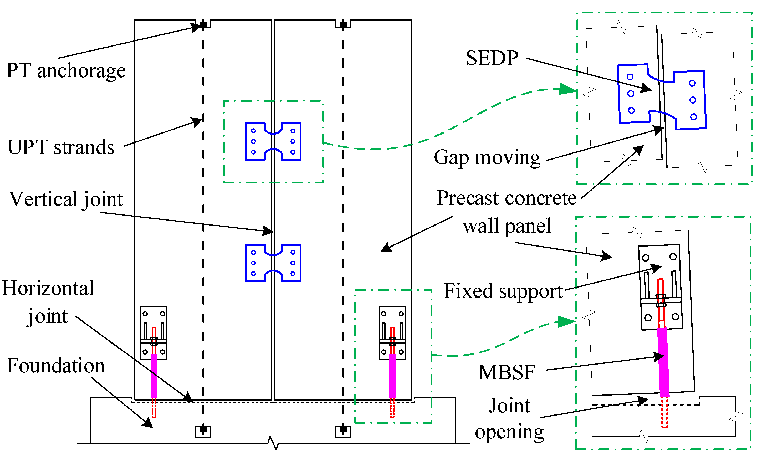
2. Concept and Configuration of the Proposed System

Figure 1 shows the configurations of the proposed precast rocking walls incorporating tension–compression and shear steel energy dissipaters (PRW-TSD). The rocking wall in the system consists of two or more precast concrete wall panels spliced together. Each wall panel has a polyvinyl chloride duct embedded in the center for unbonded post-tensioning (PT) strands to connect the foundation. The wall panels are erected with a grouting layer between them and the foundation, without any connecting reinforcements except the PT strands. Several tension–compression energy dissipaters, called miniature bar-type structural fuses (MBSFs) [30,31], are set across the horizontal joints between the wall panels and the foundation. Simultaneously, the precast wall panels are connected to each other by shear energy dissipation plates (SEDPs) at the vertical joints between the wall panels. During an earthquake, the horizontal joint between the wall panel and the foundation (wall-footing joint) will open and close in an alternating fashion due to the rocking behavior, and the MBSFs will produce tension–compression alternative deformation. In addition, since the two sides of the vertical gap between the two adjacent wall panels move conversely due to the seismic action, the SEDPs will deform in a shear mode. Therefore, during the rocking behavior of the precast walls under seismic loading, the MBSFs and SEDPs can dissipate earthquake-input energy by tension–compression and shear plastic deformations, respectively. As a result, the precast wall panels are protected, with little or no damage caused by the earthquake. Moreover, the MBSFs and SEDPs can also help to adjust the lateral stiffness and load-bearing capacity of the PRW-TSD system together with the prestressing tendons. The prestressing force generated by the PT strands improves the self-centering capacity and reduces the residual drift of the system under earthquake actions. The PRW-TSD system is constructed by dry connections, which eliminate complex steel bar alignment work and concrete pouring at construction sites. The working labor is also reduced due to the convenient and speedy construction process. Note that the MBSFs and SEDPs are all mounted onto the external sides of the wall panels, which are easy to repair and replace after earthquakes.

3. Experimental Program

3.1. Description of the Test Specimen

3.1.1. Specimen Details

According to the proposed PRW-TSD system, the precast concrete wall panels were expected to exhibit little to no damage after earthquake actions. Therefore, two precast concrete wall panels, described in Section 3.1.2, were designed and produced to make one rocking wall specimen, as shown in Figure 2. The two panels were located on the foundation beam with a 10-mm wide vertical gap. Two bundles of prestressing strands, each of which consisted of four 15.2 mm diameter strands, were employed to connect the foundation. A post-tension force equal to 480.4 kN was applied through the strands for each panel. To investigate the influence of the steel energy dissipaters on the seismic performance of the whole system, three different combinations of MBSFs and SEDPs were mounted onto the rocking wall specimen for three quasistatic reversed-cyclic lateral loading tests. The three test cases were recorded as RW1-1, RW1-2, and RW1-3. SEDPs of the same configuration were applied to all three loading test cases, while the usage of the MBSFs varied.
The rocking wall specimen was first loaded (referred to as Test RW1-1) with only one type of energy dissipater, i.e., four SEDPs installed on the two sides of the specimens. Then, new SEDPs were replaced for the second test (referred to as Test RW1-2), and four MBSFs with Belleville springs were mounted at the bottom corners of the test specimen. The Belleville springs could retain a certain gap between the bolted nuts and the fixed support to control the function time of the MBSFs, which could perform as a hierarchical energy dissipation (HED) mechanism [32]. To study the possibility of achieving the HED mechanism for the PRW-TSD system, 7 mm wide gaps, described in detail in Section 3.1.4, were set at the connection of the MBSFs and the wall in Test RW1-2, which made the installed MBSFs begin to function when the rocking wall specimen experienced a 1% drift deformation. The last test (referred to as Test RW1-3) was conducted with the new SEDPs and the MBSFs (without Belleville springs). The test matrix is summarized in Table 1.

3.1.2. Details of the Concrete Elements

Figure 3 shows the details of precast concrete elements in the test specimen designed based on Chinese Code GB50011 [33] and GB50010 [34]. The precast concrete wall panel was cast in a local precast concrete factory with a thickness of 200 mm, a length of 820 mm, and a height of 3475 mm. An enhanced loading beam was also made as a portion on the panel with a width of 240 mm, a length of 660 mm, and a height of 320 mm. A 30 mm deep groove was reserved on the top surface of the foundation beam for the embedment of the panels and the 15 mm thick grouting layer. PVC pipes with a diameter of 75 mm were embedded at the centers of the wall panels and the corresponding locations of the foundation beam. Thru-holes were reserved at appropriate locations of the wall panels to facilitate the installation and replacement of the energy dissipaters, and threaded sleeves were preembedded into the foundation beam for the attachment of MBSFs. Considering that crushing of the concrete is undesirable for the self-centering system with additional energy dissipaters, 10 mm thick steel plates were employed at the appropriate positions of the wall panel to protect the crucial local areas, especially the wall toes. Rebar with diameters of 16 mm and 8 mm were adopted as the longitudinal reinforcing rebar of the wall panels, and lateral reinforcing rebar with a diameter of 10 mm were spaced at 200 mm intervals.

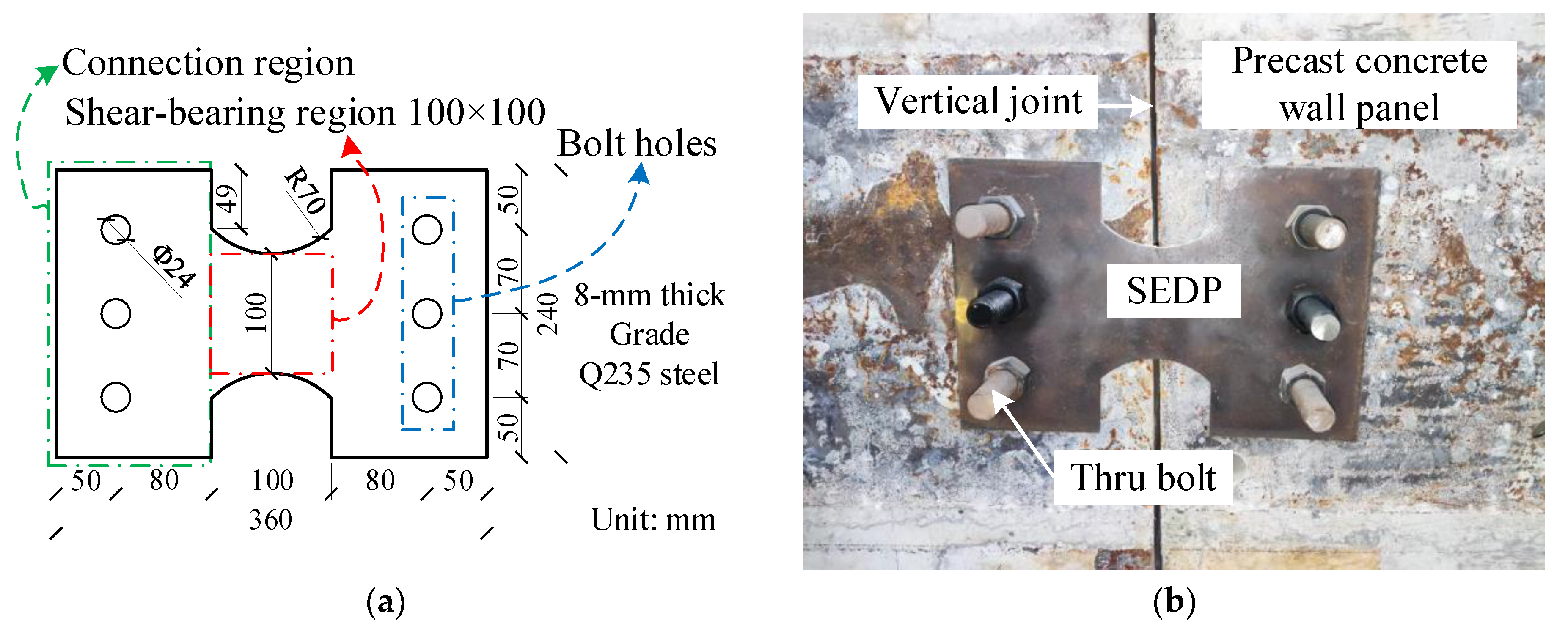
3.1.3. Details of Shear Energy Dissipation Plates

The PRW-TSD system is proposed and conceived for shear wall-frame structures, for which the lateral drift limit for the elastic state is stipulated as 0.125% according to the Chinese code for seismic design, i.e., GB50011 [33]. Therefore, the SEDPs for the test specimen were designed theoretically to yield when the rocking wall specimen reached the drift level of 0.125%. To simplify the design process, some assumptions were made, which are presented as follows: (1) The precast wall panels maintained elasticity during the loading progression; (2) After the SEDPs yielded, the two wall panels rotated around the corresponding toes of each panel; (3) The MBSFs were excluded from the load-bearing components. Based on the calculation method for coupled wall systems [35,36] and the abovementioned assumptions, the total shear bearing demand for the SEDPs was obtained as 436.53 kN at the design-level drift of 0.125%. The shear yield strength of a steel panel was evaluated based on the following equation [37]:
V p = f y 3 t b ,
where f y is the yield strength of the obtained steel and t and b are the thickness and width of the critical shear-bearing region of the steel plate, respectively. In this paper, SEDPs were made from an 8 mm thick Q235 steel plate. The configuration of the SEDP is shown in Figure 4a. The critical shear-bearing region was expected to transmit the internal force of the dual rocking wall system and dissipate energy. Circular holes were preslotted at both sides of the connection regions and fixed to the wall panels using thru bolts, as shown in Figure 4b.

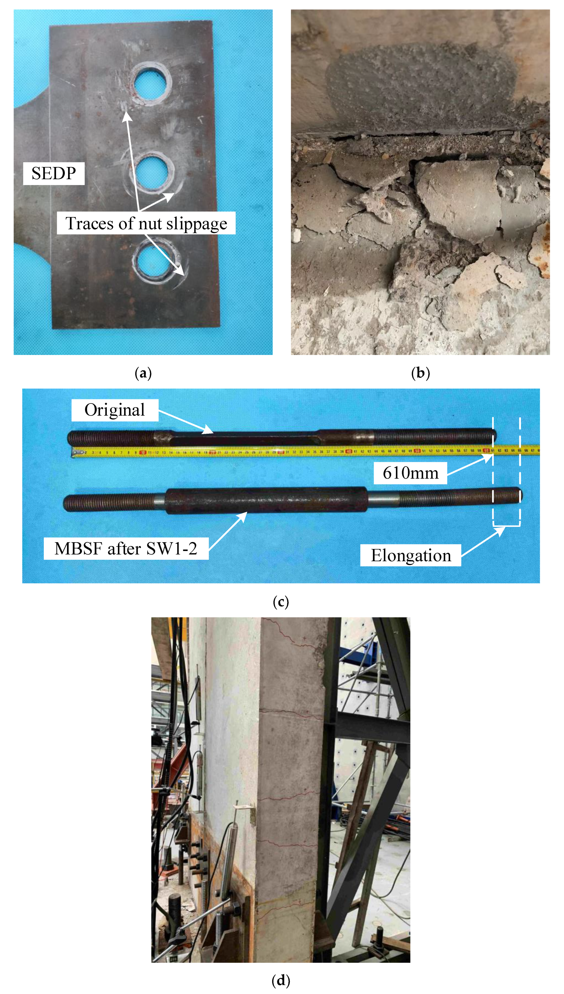
3.1.4. Details of Miniature Bar-Type Structural Fuses

In previous studies [30,31,32], MBSFs have been proven to exhibit superior energy dissipation capacities. As shown in Figure 5a, the MBSF comprises two components: a Q235 steel central energy dissipation core and a Q345 steel confining tube. The central energy dissipation core was machined from 24 mm diameter conventional mild steel bars, which could be separated into 3 portions, i.e., the weakened portion, the elastic transition portion, and the screwed connection portion. With respect to the weakening process, the 120 mm long screw portion was used to connect the preembedded threaded sleeves in the foundation beam, and the 175 mm long screw portion was connected to the fixed support mounted on the wall panel through M24 high strength nuts, as shown in Figure 5b. The confining tube was a 5.5 mm thick, 280 mm long seamless steel tube with a diameter of 36 mm. The Belleville spring, with a spacing of 7 mm, was assembled between the MBSF and the fixed support in Test RW1-2 to make the MBSFs yield at the designed drift level. The lower edge of the nut was located 21 mm away from the support after the Belleville spring was installed, and the spacing became 14 mm once the Belleville spring was completely compressed, as shown in Figure 5b.

3.1.5. Material Properties

The two wall panels and the foundation beam of the specimen were cast with C40 concrete, and three 150 mm × 150 mm × 150 mm control cubes for the utilized concrete were produced and cured with the test specimens in the same surroundings. According to the standard coupon test recommended in GB/T50081-2019 [38], the cubic compressive strength of the used concrete was 42.2 MPa. HRB400 steel rebar were employed for the lateral and vertical reinforcing rebar of the wall panels. Based on GB/T228.1-2021 [39], three coupon tests were conducted for each kind of key dissipating component in the two kinds of energy dissipaters to determine the basic mechanical indices. The material properties of all the steel materials are summarized in Table 2.

3.2. Test Setup

The cyclic lateral loads were applied to the loading beam by a 100 T electrohydraulic servo actuator, while two out-of-plane braces were installed to maintain the stability of the wall panels, as shown in Figure 6. The foundation beam was anchored to the rigid ground by four thick screws, and the limit mechanical jacks were placed laterally at both sides of the foundation beam to avoid undesirable horizontal slippage. The post-tension strands passed through the reserved ducts in the wall panels and the foundation beam. Two hydraulic jacks connected with the strands were mounted on the top of the specimen to apply and maintain the predetermined prestressing force to the system. A hinged joint that could slide vertically was mounted between the two loading beams to transmit the applied loads to the two panels and ensure that the two panels would rotate independently under lateral loading. The energy dissipaters for one test were replaced after the test was completed.
During the loading process, the concentrated forces applied by the actuator and the lateral displacement of the wall top were both obtained from the built-in sensor of the actuator. The critical displacement of the specimen and the deformation of the energy dissipaters were measured by displacement sensors. The relative vertical displacements of the connection regions in the SEDPs were recorded as the shear displacements. Through-core load cells were applied to the top of the strands to control the tensioning process and gauge the prestressing force value during the loading process.

3.3. Loading Protocol

This experimental program consisted of three successive quasistatic reversed-cyclic lateral loading tests on the specimen. The drift-controlled loading protocol recommended by ACI 374.1-05 [40] was adopted, and the drift was the ratio of the lateral displacement at the center of the loading beam cross section, i.e., the position of the actuator action point, to the vertical distance from the loading point to the rocking wall bottom. Two levels of preloading cycles were performed before the formal loading, of which the lateral loading displacement equaled 1 mm and 2 mm. The preloading procedure was performed to check the functionalities of the loading system, measuring instruments, etc. In the formal loading stage, the drift of each loading level was 0.1%, 0.125%, 0.2%, 0.33%, 0.5%, 0.67%, 1%, 1.5%, 2%, and 2.5%. Each drift level consisted of three fully reversed cycles, as shown in Figure 7. The test stopped once a dissipater cracked or the lateral strength dropped to 85% of the ultimate load.

4. Experimental Results and Discussion

4.1. Test Observation

Tests RW1-1, RW1-2, and RW1-3 were tested in sequence. For RW1-1, at the loading drift level of 0.5%, the visible grout near the wall footings cracked slightly, and the wall-footing connection decompressed with the wall panels detached from the foundation. As the rocking wall was connected to the foundation through the infill grout, the phenomenon indicated that the rocking wall began to rotate at the wall toe. Simultaneously, the SEDPs initiated shear deformation with a measured relative displacement of 2.45 mm. As there was mutual misalignment between the two wall panels, the SEDPs could be considered to work between the individual walls. The SEDPs yielded at the loading drift level of 0.67%, of which the shear displacement approached 5.88 mm. The phenomenon indicated that the configuration realizes the original design concept for the energy dissipation of the system. The wall panel could be observed to rotate around the wall toe. A sound was heard near the bolts connecting the SEDP during the 2% drift loading process, which was attributed to the result of the slip between the nut and the SEDP. At the end of the test, the SEDPs were removed, and traces of nut slippage were observed, as shown in Figure 8a. Following the drift level exceeding 2%, significant cracking of the grout between wall panels and foundation was observed, as shown in Figure 8b. There was little damage found in the two wall panels, while the SEDPs exhibited irreversible residual plastic deformation. Since the SEDP is designed as replaceable in the future application, the specimen could be regarded to fail as expected.
Test RW1-2 was loaded second. In addition to SEDPs, Test RW1-2 was fitted with MBSFs with additional Belleville springs. The purpose of RW1-2 was to verify the possibility of utilizing multiple energy dissipaters to achieve HED. Since the grout had lost its bonding capacity, the wall panels lifted, overcoming only the pressure on the wall-footing connection due to the tension of the PT strands and the self-weight of the wall panels at the beginning of the second test. Similar to Test RW1-1, the newly installed SEDPs also yielded at the 0.67% loading drift level. As the loading drift level increased, the Belleville springs were compressed continuously, and they were fully compressed before 1.0% loading drift, which meant that the MBSFs became involved and the specimen entered the second mechanical stage. The residual deformation of the MBSFs gradually developed at the later stage of the test, and the cores buckled at the pressurized side of the specimen. Therefore, the central energy dissipation core of the MBSF was stuck in the confining tube due to the restraining effect after the test, as shown in Figure 8c.
Note that the specimen was loaded to check the behaviors with large SEDPs causing minor damage of the concrete at wall toes before Test RW1-3 [41]. The damage potentially caused the loss in the bearing capacity of the specimen to some degree. As for Test RW1-3, since no Belleville spring was installed, the SEDPs could enter operational status once the wall panels detached from the foundation beam at the drift level of 0.5%, while the wall panels commenced to misalign, leading to the shear deformation of the SEDPs. Both energy dissipaters yielded by loading to 0.67% drift level, and with MBSF, the corresponding drift for yielding was much less than that for RW1-2. Narrow horizontal cracks appeared on both sides of the wall specimen at the later stage of Test RW1-3. Figure 8d shows the cracks in the wall panel on the tensioned side when loaded positively up to the 2% drift level. The cracks close automatically as the loading drift unloads to zero due to the prestressing strands. Similar to Test RW1-2, the MBSF underwent irreversible plastic deformation, and the central energy dissipation core stuck in the confining tube after the test.
In general, no particularly significant cracking or serious concrete spalling occurred during the tests of the specimen, and no damage to the concrete at the regions for the energy dissipaters appeared due to the restraining effect of the embedded steel plates. Significant plastic deformation concentrated in the SEDPs and MBSFs, while only slight damage to concrete appeared in the precast wall panels. Therefore, it could be concluded that the proposed system shows good resilience.

4.2. Hysteretic Curves

The relationships of the lateral loading force versus the loading drift of the three tests are shown in Figure 9.
The hysteretic curves of Test RW1-1 exhibited typical flag-shaped loops after the wall panels were lifted. An obvious inflection point appeared in the curves at the drift level of 0.67%, which corresponded to the yielding of the SEDPs. As the drift increased, the hysteresis areas grew significantly due to the continuous plastic deformation of the SEDPs, indicating the enhanced energy dissipation capacity of the system.
The SEDPs also yielded at the drift level of 0.67% in Test RW1-2, at which the first inflection point of the curves appeared and the system reached the yielding stage. During the process of drift level rising to 1.5%, two events successively followed: (1) the Belleville springs were completely compressed (see Figure 5), and the MBSFs began to function, leading to an obvious increasing portion in the curves; (2) the MBSFs yielded rapidly after working, and the curves showed the second inflection point at 1.5% drift level, indicating full yielding of the energy dissipaters. In the loading stage above 1.5% drift, both the MBSFs and the SEDPs deformed plastically, participating in energy dissipation jointly. Once the Belleville spring was compressed, the MBSFs were initiated to restrict the opening and closing of the wall-footing joint gap, so that the strength of Test RW1-2 was greater than that of the corresponding Test RW1-1. Compared to RW1-1, the strength of RW1-2 (229.2 kN) was 33% larger than RW1-1 (172.4 kN) at the maximum loading drift level.
Theoretically, the loading strength of Test RW1-3 should be higher than that of Test RW1-2. However, the local concrete damage weakened the wall panel stiffness and consequently affected the strength of Test RW1-3. The achieved strength was close to that of Test RW1-2 because the MBSFs could provide a certain anti-overturning force in the early loading stage. However, with the yielding of the MBSFs and SEDPs at the 0.67% drift level, the anti-overturning force provided by the energy dissipaters was limited, so that the system strength was relatively lower compared to that of Test RW1-2.
The structural capacities of energy dissipation and self-centering tended to be mutually balanced. Overall, the proposed system achieved the optimal solution of energy dissipation and self-centering capacities. The hysteresis curves of the PRW-TSD were significantly fuller compared to the curves of the rocking wall structure without dissipaters [10], which indicated the nonnegligible effect of the dissipaters in improving the structural energy dissipation capacity. However, compared to the hysteresis curve of the monolithic shear walls [42], the fullness of the curves of the PRW-TSD was obviously weaker. It is necessary to acknowledge that the residual deformation of the PRW-TSD structure following unloading was extremely low, i.e., the self-centering behavior of the proposed structure was quite excellent relative to that of the monolithic shear walls.

4.3. Skeleton Curves

The skeleton curve of the tests was obtained by connecting the peak points of the first cycle at each loading level in the hysteresis curves [43], as shown in Figure 10. The curves were basically symmetrical, indicating that the system presented similar mechanical behaviors in both loading directions. Since no serious damage occurred to the wall panels during the entire loading process, and only the energy dissipaters yielded and dissipated input energy, the lateral strength of the system continued to increase as the loading drift grew. The characteristic states during positive loading are shown in Table 3, with the yield states obtained by linear fitting of the skeleton curves, and the peak point of curves were taken as the ultimate limit states since the specimen never shows significant damage. According to the stipulation in the Chinese seismic design code [33], the maximum story drift of concrete shear wall-frame structures in the plastic state should never exceed 1%. As shown in Figure 10, the lateral strength of the specimen did not degenerate at the 2.5% drift level, indicating that the system had favorable deformability for practical buildings.
The inflection points of the skeleton curves for all three tests appeared at the same loading drift, which verified that the SEDPs in all tests yielded at the 0.67% drift level, as described above. However, the lateral strength of Test RW1-1 was the highest before the SEDPs yielded because it was the first test of the specimen, and the bond of the infill grout between the wall panels and the foundation element had to be overcome. Compared with Test RW1-1, Test RW1-2 showed a higher lateral strength at the same corresponding loading drift due to the function of the MBSFs. The overall trend of the Test RW1-3 curves was similar to that of Test RW1-2, but the lateral strength remained relatively lower than the corresponding strength of Test RW1-2 for the reasons mentioned above.
The ratio of ultimate drift to yield drift was taken as the ductility factor. Comparing the ductility factors of the three tests, it was shown that the ductility of RW1-3 was relatively weaker than that of RW1-2 due to the non-setting of Belleville springs for MBSFs. The ductility of RW1-1 was optimal, due to the lowest number of dissipaters and the lack of dissipative bars, which indicated that the restraining effect of the dissipative bars on the concrete elements reduced the deformation capacity of the structure. Meanwhile, the ductility factor decreased gradually with the growing loading sequence, which demonstrated that the cumulative structural damage weakened the ductility performance.

4.4. Stiffness and Strength Deterioration

The index of secant stiffness to measure the stiffness degradation is defined in Chinese Standard JGJ/T101 [43]. The peak point of the first cycle of each loading level was taken for the calculation of the secant stiffness, and the obtained results are shown in Figure 11. The stiffness of Test RW1-1 was significantly greater than that of the other two tests at a small drift level, indicating that the bond capacity of the grout between the wall panels and the foundation contributed significantly to the stiffness of the undamaged wall system. At the later stage of Test RW1-2, the MBSFs participated in the energy dissipation, slowing down the stiffness degradation of the system considerably. Due to the minor local crushing of the concrete before Test RW1-3, the stiffness of Test RW1-3 remained relatively lower than that of Test RW1-2. Furthermore, the concrete cracking on both sides of the wall panels also contributed to the reduction of the stiffness in Test RW1-3. Therefore, it was necessary for the system to enhance the sides of the wall panels and avoid the development of concrete cracks.
The average values of strength in the positive and negative loading directions were selected for the evaluation of strength deterioration. The ratio of the peak lateral strength of the second or third loading cycle at each drift level to that of the first cycle was calculated separately as the strength degradation factor, which is shown in Figure 12. All strength degradation factors of the three tests were greater than 0.93, demonstrating that the lateral strength of the specimen was extremely steady during the reversal cyclic lateral loading tests. The unstable factors at the low drift level were caused by some gaps in the loading system.

4.5. Energy Dissipation Capacity

The cumulative dissipated energy at each loading drift, i.e., the sum of all the energy dissipated until a certain loading drift, was calculated for the three tests, as shown in Figure 13a. At the beginning of the three tests, the specimen remained elastic, and the cumulative dissipated energy remained almost unchanged. Before the 0.67% drift level, the cumulative dissipated energy of Test RW1-1 was slightly higher than that of the other two tests because the infill grout at the wall-footing connection played a role in improving the energy dissipation capacity of the system for the first minor earthquake attack. Since the quantities of energy dissipaters in Tests RW1-2 and RW1-3 were more than that of Test RW1-1, their cumulative dissipated energy became higher after the yielding of the steel energy dissipaters. Local damage actually weakened the energy dissipation capacity; as a consequence, Test RW1-3 remained lower than Test RW1-2 in terms of cumulative dissipated energy.
The equivalent viscous damping ratio, ζeq, is widely employed to evaluate the energy dissipation capacity of members in many structural seismic experiments [5,16]. In this study, ζeq is employed and calculated for the first hysteresis loop at each drift level of the tests, as shown in Figure 13b. Test RW1-1 exhibited high ζeq in the early stage due to the effect of the infill grout. In the later stage, more energy dissipaters in both Tests RW1-2 and RW1-3 helped to increase ζeq rapidly, which meant that the energy dissipation of the system was mainly concentrated in the energy dissipaters. At the end of the test, the ζeq values of Test RW1-2 showed no noticeable decrease, indicating a high energy dissipation capacity. This indicates that an appropriate delay in the timing of partial energy dissipaters into operational status could improve the energy dissipation capacity of the system under major earthquake effects. The values of ζeq in Test RW1-3 were marginally higher than those in Test RW1-2 at the initial loading stage because the MBSFs in Test RW1-3 functioned earlier than those in Test RW1-2. However, due to local concrete crushing, ζeq of Test RW1-3 dropped significantly compared with that of Test RW1-2.
The lateral displacement of the wall top was contributed to by both the flexural–shear deformation and the rigid body rotation of the wall panel [44]. The local concrete crushing before RW1-3 and Test RW-3 was conducted on the damaged wall panels. Therefore, compared with RW1-2, the contribution of the flexural–shear deformation of the wall panel to the lateral displacement of the wall top increased in Test RW 1-3, and the rigid body rotation decreased. Under the same loading drift level, the angle of rigid body rotation in RW1-3 was less than that in Test RW1-2, i.e., the uplifting height of the wall toe was less than that of Test RW1-2, the deformation of MBSFs was smaller, and the energy dissipation capacity was not developed sufficiently.
The cumulative dissipated energy and equivalent viscous damping for the above-mentioned maximum story drift level of 1% [33] and limit drift level of 2.5% are summarized in Table 4. The cumulative dissipated energy of RW1-2 and RW1-3 showed little difference from that of RW1-1 at the drift level of 1%, whereas the difference was significant at the drift level of 2.5%, which indicated that MBSFs possessed considerable potential for enhancing the structural energy dissipation under extremely rare earthquakes. The comparison of ζeq demonstrated that the energy dissipation capacity of the structure achieved a superior level at 1% drift level. Although Belleville springs were incorporated into the MBSFs in RW1-2, the ζeq was 17.6% greater than that of RW1-1 at the drift level of 1% and 34.8% at the 2.5% drift level.

4.6. Self-Centering Capacities

In this paper, the self-centering factor η of the first cycle for each drift level is adopted to evaluate the self-centering capacity of the system, which is calculated as follows:
η = Δ r Δ
where Δ r is the residual displacement of each drift level after unloading, and ∆ is the maximum displacement of the corresponding drift level. Δ takes the average of the residual deformation in the positive and negative directions at each loading drift level. The relationships of η versus loading drift of the three tests are shown in Figure 14. During the loading process, the values of η in the three tests remained relatively low, indicating the satisfactory self-centering capacity of the proposed system mainly relying on the steel strands. As the plastic deformation of the steel energy dissipaters required restoring force when the loaded specimen returned to its original position, the overall η of Tests RW1-2 and RW1-3 was slightly higher than that of Test RW1-1 because more energy dissipaters were installed in Tests RW1-2 and RW1-3. The above showed that additional dissipaters have a significant positive effect on the strength and energy dissipation capacity of the structure; however, it is undeniable that this leads to a weakening of the self-centering capacity. Therefore, the relationship between the performance demands should be weighed for the design of PRW-TSD systems. Furthermore, the crushes of the wall panels actually reduced the plastic deformation of the energy dissipaters in Test RW1-3, especially the SEDPs, leading to a relatively higher self-centering capacity of Test RW1-3 than that of Test RW1-2.

5. Numerical Simulation

To further investigate the seismic performance of the PRW-TSD system under horizontal seismic action and to explore the potential of applying Belleville springs to achieve the HED mechanism, a numerical analysis was developed in this paper by OpenSees software version 3.3.0 [45].

5.1. Finite Element Modeling

The prototype of the finite element model was the specimen in the test of this paper, as shown in Figure 15. The precast concrete wall panel was built using the dispBeamColumn element [46], which was developed on the basis of displacement formulation, and it took into account the distribution of plasticity along the element by means of the designated number of integration points in the fiber cross-section. The wall panel section was modelled with the refined FiberSection, which included the reinforcing rebar fibers in tension and the concrete fibers in compression. The Steel02 material was employed to simulate the steel reinforcement, while Concrete02 and Concrete01 were applied to simulate the core restrained concrete and the cover concrete, respectively. Rigid arms created by ElasticBeamColumn elements were attached to the wall panel elements for the connection of the energy dissipaters and for the establishment of the contact with the foundation constructed with zeroLength elements. The zeroLength elements effectively modelled the transfer of base shear and vertical compression, and accurately simulated the opening and closing behavior of the horizontal joints between the wall panels and the foundation. The elements transmitting the base shear forces were formed by Elastic materials, and the elements transmitting the vertical compression forces used ENT materials with great stiffness and the were capable of bearing only pressure. The top nodes of the two wall panels were coupled in the horizontal direction by the equelDOF command to simulate the action of the hinged joint in the test. The PT strands were modelled by truss elements, and the associated uniaxialMaterial was steel02, which could assign initial stress. One node of the truss element was coupled with the top node of wall panel using the equelDOF command, and the other node was fixed to the foundation.
The steel energy dissipaters were the only energy dissipating components in the PRW-TSD system, and the reasonability of the model was particularly important to evaluating the energy dissipation capacity of the structure. The force applied to the wall panel was consistently located in the longitudinal direction along the wall panel during the shear deformation of SEDP; therefore, the SEDP could be simulated by a twoNodeLink element connecting rigid arms at the same height, and the material model of steel02 was adopted in the local y-direction. The mechanical properties of the MBSF based on Belleville springs were more complex. As shown in Figure 16a, multiple parallel and series twoNodeLink elements were applied for the simulation of the dissipater. Nodes i and j were fixed to the foundation and onto the additional rigid arm at the bottom of the wall panel, respectively, and all the elements between these two points were jointly employed to model the MBSF with Belleville springs. Element J was constructed with the steel02 model to simulate the MBSF, and the material parameters were determined referring to the experimental results in the literature [30]. Nodes m and n did not coincide in spatial location, but all degrees of freedom of the two nodes were coupled through employing the equelDOF command. Both elements N and M were applied to simulate the constraints on the upper end of the MBSF during the loading process. As shown in Figure 16b, element N was associated with ElasticMultiLinear material, and the value of ∆gap equaled the one of the Belleville springs, which was −7 mm for RW1-2 in this paper. As shown in Figure 16c, element M was associated with ENT material, and the tensile loading capacity of element M was set zero.

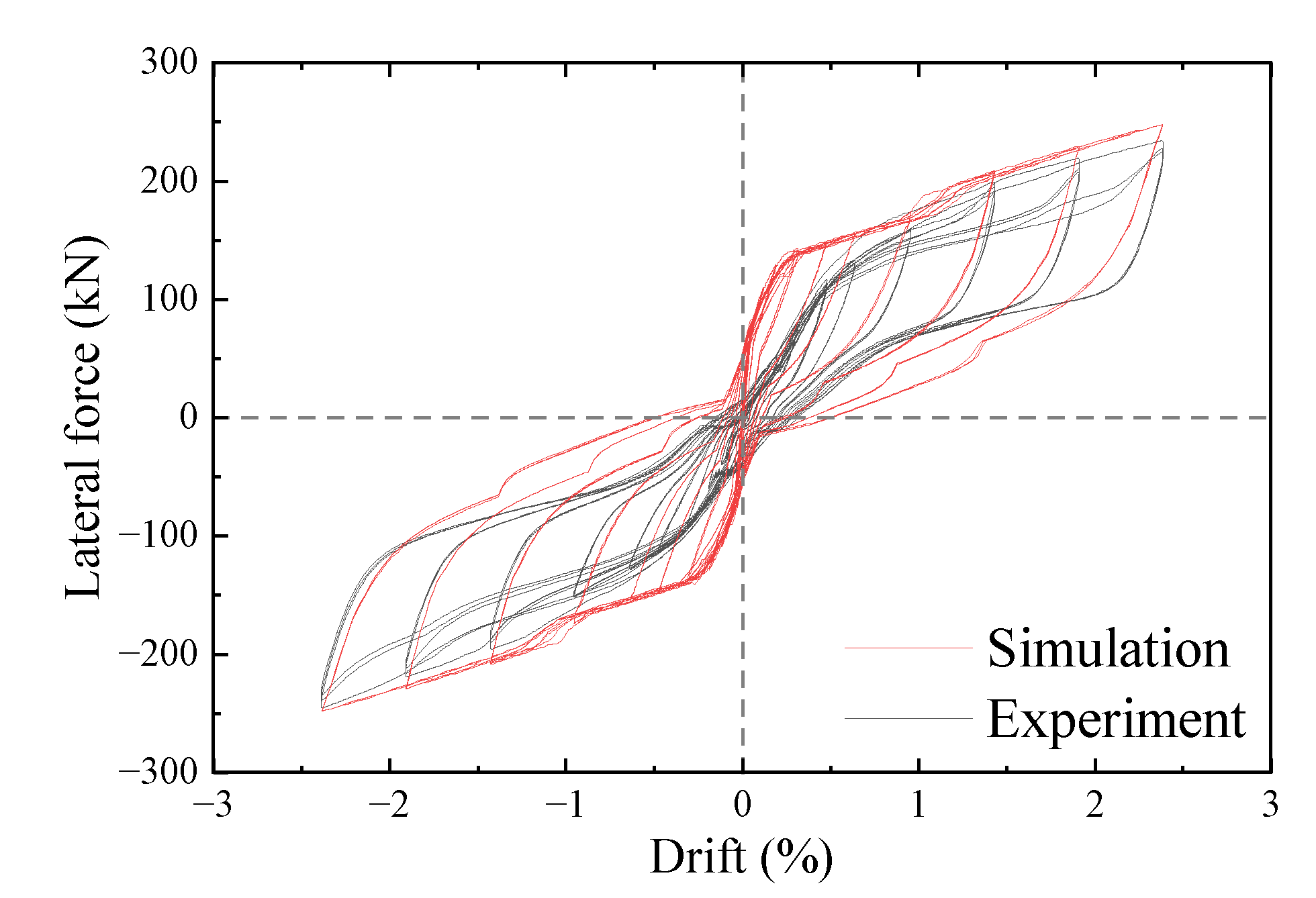
5.2. Simulation Results

The same loading protocol as the test was applied to the top node of the wall panels in the above model, and the hysteresis curve of the finite element analysis compared with Test RW1-2 is shown in Figure 17. All the hysteresis loops of the finite element curves were relatively full, which matched the experimental curves and provided a relatively accurate simulation of the structural energy dissipation capacity. For RW1-2, the curves showed an obvious sharp increase at the design drift level, indicating the HED mechanism simulated by the model. Overall, the finite element model presented a satisfactory simulation for the test; therefore, the model could be applied to investigate the seismic performance of the studied structure.

5.3. Parametric Analysis

The parametric analysis of the single parameter variation was performed based on the above numerical model with the design factors of RW1-2. The original parameters included the post-tension force factor; the number of SEDPs, ∆gap, and the diameter of the MBSF with values of 0.5, 4, 7, and 24 mm, respectively, and the post-tension force factor referred to the ratio of the initial post-tension stress to the yield strength of the PT strands. The same loading protocol as the previous test was applied to the finite element model, and the skeleton curves were extracted from the obtained hysteresis curves with the same method as before, as shown in Figure 18.
As shown in Figure 18a, the strength of the structure was positively correlated with the initial post-tension force, and the larger initial post-tension force offered stronger initial stiffness to the structure. It should be noted that as the initial post-tension force increases to a certain level, an abrupt change in the strength of the structure occurred at greater drift levels because the larger initial prestress results in the yielding of PT strands at greater drift levels. Once the PT strands in rocking structures yielded, the risk of structural failure and post-earthquake repairability extremely increased. Therefore, in the design of PRW-TSD system, the initial prestress should be limited under the premise of ensuring the initial stiffness of the structure. As shown in Figure 18b, the number of SEDPs significantly affected the strength of the structure, and a greater number of SEDPs caused a higher strength of the structure. In fact, the increase in the number of SEDPs enhanced the total shear bearing capacity of the coupling members in a coupled wall structure [35]. The increment in the total load-bearing capacity of SEDPs prolonged the range of the drift for the overall rotation of the two wall panels, the wall toes of trailing wall were lifted to a larger height [47], and the MBSFs at these locations operated. Therefore, the growth in the number of SEDPs led to a decrease in the drift level corresponding to the abrupt change in the slope of the curve. Due to the effect of the number of SEDPs on the rotation mode of the wall in the structures with a great number of SEDPs, the PT strands in the trailing wall yield at a larger drift level. Consequently, during the design of the PRW-TSD system, the stress of PT strands should be checked if the number of SEDPs exceeded certain limitations.
As shown in Figure 18c, the ∆gap had little effect on the strength of the structure, but the local enlargement of the skeleton curve showed that the growth of the ∆gap increased the drift level corresponding to the abrupt change in the slope of the curve, resulting in a relatively weaker strength of the structure at a larger drift level. It could be drawn that the MBSFs with reasonable gaps could yield at specifically-designed drift levels, at the slight expense of structural strength, and effectively reduce the repair cost after an earthquake. As shown in Figure 18d, the diameter of the MBSF affected the strength of the structure after the MBSF functioned with the same value of ∆gap, and the larger diameter of the MBSF led to the greater strength of the structure. Therefore, the large diameter MBSF could effectively enhance the structural strength under major earthquakes. However, because of the non-negligible restraint effect of MBSFs with large diameters at wall toes, the flexural deformation of wall panels under horizontal earthquake forces may be increased to a certain extent. Considering the experimental phenomena of RW1-3, it is recommended that the design of the PRW-TSD system should be checked for cracks in the tensile edges of wall panels, considering the effect of MBSFs.

6. Conclusions

A precast rocking wall system incorporating tension–compression and shear steel energy dissipaters is proposed. Three quasistatic tests were consecutively carried out on a rocking wall specimen to investigate the effects of different energy dissipater parameters on the seismic performance of the proposed system. Meanwhile, the experimental results were simulated by numerical models based on OpenSees software, and parametric analysis was performed. According to the results of experimental and numerical analysis, the following conclusions can be drawn:
  • The wall panels showed no significant damage but good self-centering capacity, indicating the satisfactory resilience of the proposed system. Both the shear energy dissipation plates and the miniature bar-type structural fuses exhibited good energy dissipation performance during the test process, leading to flag-shaped hysteresis loops of the proposed system.
  • The minor damage in the wall panels after several reversal cyclic loading tests weakened the stiffness of the proposed system, resulting in a relatively worse performance of the energy dissipaters, which should be avoided by improving the structural details of the wall panels.
  • Test RW1-2 verified the possibility of applying multiple energy dissipaters to achieve a hierarchical energy dissipation (HED) mechanism of a structure, providing a new method for the development of highly efficient structural energy dissipating systems.
  • The effect of SEDPs on the rotation mode of the wall panels influenced the elastic-plastic status of the prestressing tendons and the local concrete at greater drift levels based on parametric analysis. The combination of Belleville springs with MBSFs provided significant effectiveness in achieving HED mechanism for the structure.
  • The finite element model proposed in this paper effectively simulated the effects of the Belleville springs, and parametric analysis showed that the springs cleverly controlled the yielding of MBSFs at the designed drift level. The numerical model accurately simulated the global hysteresis behavior of PRW-TSD with cyclic loading tests as well, which provided a foundation for the subsequent dynamic analysis. However, the numerical model idealizes the deformation pattern of the wall panels and slightly overestimates the structural strength compared to the experimental results.

Author Contributions

Conceptualization, J.L. and D.G.; methodology, D.G., Z.P. and Y.L.; software, Z.P. and Y.L.; validation, Z.P. and D.G.; formal analysis, J.L.; investigation, J.L.; resources, J.L. and D.G.; data curation, Z.P.; writing—original draft preparation, Z.P.; writing—review and editing, D.G., J.L. and Z.P.; project administration, D.G.; funding acquisition, J.L. and D.G. All authors have read and agreed to the published version of the manuscript.

Funding

This work was supported by the National Natural Science Foundation of China (No. 52278154), the Natural Science Foundation of the Higher Education Institutions of Jiangsu Province (No. 23KJB560019), and the China-Pakistan Belt and Road Joint Laboratory on Smart Disaster Prevention of Major Infrastructures.

Institutional Review Board Statement

Not applicable.

Informed Consent Statement

Not applicable.

Data Availability Statement

Not applicable.

Conflicts of Interest

The authors declare that there is no conflict of interest.

References

  1. Hasanali, M.; Roy, K.; Mojtabaei, S.M.; Hajirasouliha, I.; Clifton, G.C.; Lim, J.B. A critical review of cold-formed steel seismic resistant systems: Recent developments, challenges and future directions. Thin-Walled Struct. 2022, 180, 109953. [Google Scholar] [CrossRef]
  2. Yilmaz, F.; Mojtabaei, S.M.; Hajirasouliha, I.; Becque, J. Behaviour and performance of OSB-sheathed cold-formed steel stud wall panels under combined vertical and seismic loading. Thin-Walled Struct. 2023, 183, 110419. [Google Scholar] [CrossRef]
  3. Papargyriou, I.; Mojtabaei, S.M.; Hajirasouliha, I.; Becque, J.; Pilakoutas, K. Cold-formed steel beam-to-column bolted connections for seismic applications. Thin-Walled Struct. 2022, 172, 108876. [Google Scholar] [CrossRef]
  4. Priestley, M.N.; Sritharan, S.; Conley, J.R.; Pampanin, S. Preliminary results and conclusions from the PRESSS five-story precast concrete test building. PCI J. 1999, 44, 42–67. [Google Scholar] [CrossRef]
  5. Twigden, K.M.; Sritharan, S.; Henry, R.S. Cyclic testing of unbonded post-tensioned concrete wall systems with and without supplemental damping. Eng. Struct. 2017, 140, 406–420. [Google Scholar] [CrossRef] [Green Version]
  6. Asadolahi, S.M.; Fanaie, N. Performance of self-centering steel moment frame considering stress relaxation in prestressed cables. Adv. Struct. Eng. 2020, 23, 1813–1822. [Google Scholar] [CrossRef]
  7. Zhu, L.H.; Zhao, C. Self-centering steel frame systems for seismic-resistant structures. Adv. Civ. Eng. 2020, 2020, 8859881. [Google Scholar] [CrossRef]
  8. Guo, T.; Xu, Z.; Song, L.; Wang, L.; Zhang, Z. Seismic Resilience Upgrade of RC Frame Building Using Self-Centering Concrete Walls with Distributed Friction Devices. J. Struct. Eng. 2017, 143, 04017160. [Google Scholar] [CrossRef]
  9. Qu, Z.; Wada, A.; Ye, L. Seismic retrofit of frame structures using rocking wall system. J. Build. Struct. 2011, 32, 11–19. [Google Scholar]
  10. Kurama, Y.; Pessiki, S.; Sause, R.; Lu, L.W. Seismic behavior and design of unbonded post-tensioned precast concrete walls. PCI J. 1999, 44, 72–89. [Google Scholar] [CrossRef]
  11. Perez, F.J.; Pessiki, S.; Sause, R. Experimental Lateral Load Response of Unbonded Post-Tensioned Precast Concrete Walls. ACI Struct. J. 2013, 110, 1045–1055. [Google Scholar]
  12. Perez, F.J.; Sause, R.; Pessiki, S. Analytical and experimental lateral load Behavior of unbonded posttensioned precast concrete walls. J. Struct. Eng. 2007, 133, 1531–1540. [Google Scholar] [CrossRef]
  13. Erkmen, B.; Schultz, A.E. Self-Centering Behavior of Unbonded, Post-Tensioned Precast Concrete Shear Walls. J. Earthq. Eng. 2009, 13, 1047–1064. [Google Scholar] [CrossRef]
  14. Kurama, Y.C. Seismic design of partially post-tensioned precast concrete walls. PCI J. 2005, 50, 100. [Google Scholar] [CrossRef]
  15. Smith, B.J.; Kurama, Y.C.; McGinnis, M.J. Behavior of Precast Concrete Shear Walls for Seismic Regions: Comparison of Hybrid and Emulative Specimens. J. Struct. Eng. 2013, 139, 1917–1927. [Google Scholar] [CrossRef] [Green Version]
  16. Restrepo, J.I.; Rahman, A. Seismic performance of self-centering structural walls incorporating energy dissipators. J. Struct. Eng. 2007, 133, 1560–1570. [Google Scholar] [CrossRef]
  17. Kurama, Y.C. Hybrid post-tensioned precast concrete walls for use in seismic regions. PCI J. 2002, 47, 36–59. [Google Scholar] [CrossRef]
  18. Smith, B.J.; Kurama, Y.C.; McGinnis, M.J. Design and Measured Behavior of a Hybrid Precast Concrete Wall Specimen for Seismic Regions. J. Struct. Eng. 2011, 137, 1052–1062. [Google Scholar] [CrossRef] [Green Version]
  19. Lu, X.L.; Yang, B.Y.; Zhao, B. Shake-table testing of a self-centering precast reinforced concrete frame with shear walls. Earthq. Eng. Eng. Vib. 2018, 17, 221–233. [Google Scholar] [CrossRef]
  20. Sritharan, S.; Aaleti, S.; Thomas, D.J. Seismic Analysis and Design of Precast Concrete Jointed Wall Systems; ISU-ERI-Ames Report ERI-07404; Iowa State University: Ames, IA, USA, 2007. [Google Scholar]
  21. Aaleti, S.; Sritharan, S. A simplified analysis method for characterizing unbonded post-tensioned precast wall systems. Eng. Struct. 2009, 31, 2966–2975. [Google Scholar] [CrossRef]
  22. Henry, R.S.; Aaleti, S.; Sritharan, S.; Ingham, J.M. Concept and Finite-Element Modeling of New Steel Shear Connectors for Self-Centering Wall Systems. J. Eng. Mech. 2010, 136, 220–229. [Google Scholar] [CrossRef]
  23. Sritharan, S.; Aaleti, S.; Henry, R.S.; Liu, K.Y.; Tsai, K.C. Precast concrete wall with end columns (PreWEC) for earthquake resistant design. Earthq. Eng. Struct. Dyn. 2015, 44, 2075–2092. [Google Scholar] [CrossRef]
  24. Guo, T.; Zhang, G.D.; Chen, C. Experimental Study on Self-Centering Concrete Wall with Distributed Friction Devices. J. Earthq. Eng. 2014, 18, 214–230. [Google Scholar] [CrossRef]
  25. Marriott, D.; Pampanin, S.; Bull, D.; Palermo, A. Dynamic Testing of Precast, Post-Tensioned Rocking Wall Systems with Alternative Dissipating Solutions. In Proceedings of the 2008 NZSEE Conference, Wairakei, New Zealand, 11–13 April 2008. [Google Scholar]
  26. Kam, W.Y.; Pampanin, S.; Palermo, A.; Carr, A.J. Self-centering structural systems with combination of hysteretic and viscous energy dissipations. Earthq. Eng. Struct. Dyn. 2010, 39, 1083–1108. [Google Scholar] [CrossRef]
  27. Liu, C.; Peng, Z.; Cui, J.; Huang, X.; Li, Y.; Chen, W. Development of crack and damage in shield tunnel lining under seismic loading: Refined 3D finite element modeling and analyses. Thin-Walled Struct. 2023, 185, 110647. [Google Scholar] [CrossRef]
  28. Liu, Y.; Li, J.B.; Lin, G. Seismic performance of advanced three-dimensional base-isolated nuclear structures in complex-layered sites. Eng. Struct. 2023, 289, 116247. [Google Scholar] [CrossRef]
  29. Wei, J.; Xie, Z.; Zhang, W.; Luo, X.; Yang, Y.; Chen, B. Experimental study on circular steel tube-confined reinforced UHPC columns under axial loading. Eng. Struct. 2021, 230, 111599. [Google Scholar] [CrossRef]
  30. Guan, D.; Yang, S.; Liu, Y.; Ge, H.; Guo, Z. Concept and behaviour of all-steel miniature bar-typed structural fuses with torsional effect. J. Constr. Steel Res. 2020, 164, 105795. [Google Scholar] [CrossRef]
  31. Guan, D.; Yang, S.; Wang, Z.; Jia, L.J.; Guo, Z.; Ge, H. Concept and behaviour of miniature bar-typed structural fuses with eccentricity. J. Constr. Steel Res. 2020, 166, 105923. [Google Scholar] [CrossRef]
  32. Yang, S.; Lin, Y.; Guan, D.; Ge, H.; Guo, Z.; Yang, H.; Liu, W. Novel Hierarchical Energy Dissipation Systems for Seismic Protection of Buildings. J. Earthq. Eng. 2023, 27, 1–32. [Google Scholar] [CrossRef]
  33. GB 50011-2010; Code of Seismic Design of Buildings. China Building Industry Press: Beijing, China, 2016.
  34. GB 50010-2010; Code for Design of Concrete Structures. China Building Industry Press: Beijing, China, 2015.
  35. El-Tawil, S.; Harries, K.A.; Fortney, P.J.; Shahrooz, B.M.; Kurama, Y. Seismic Design of Hybrid Coupled Wall Systems: State of the Art. J. Struct. Eng. 2010, 136, 755–769. [Google Scholar] [CrossRef]
  36. Shen, S.D.; Pan, P.; Miao, Q.S.; Li, W.F.; Gong, R.H. Test and analysis of reinforced concrete (RC) precast shear wall assembled using steel shear key (SSK). Earthq. Eng. Struct. Dyn. 2019, 48, 1595–1612. [Google Scholar] [CrossRef]
  37. Xu, L.Y.; Nie, X.; Fan, J.S. Cyclic behaviour of low-yield-point steel shear panel dampers. Eng. Struct. 2016, 126, 391–404. [Google Scholar] [CrossRef]
  38. GB/T 50081-2019; Standard for Test Methods of Concrete Physical and Mechanical Properties. China Building Industry Press: Beijing, China, 2019.
  39. GB/T 228.1-2021; Metallic Materials—Tensile Testing—Part 1: Method of Test at Room Temperature. China Building Industry Press: Beijing, China, 2021.
  40. ACI 374.1-05; Acceptance Criteria for Moment Frames Based on Structural Testing and Commentary. American Concrete Institute: Farmington Hills, MI, USA, 2005.
  41. Zhang, L. Research on the Seismic Performances of a Multistage Hybrid Energy Consumption Connection Prefabricated Concrete Shear Wall; Southeast University: Dhaka, Bangladesh, 2022. [Google Scholar]
  42. Zhu, Z.F.; Guo, Z.X. Seismic Behavior of Precast Concrete Shear Walls with Different Confined Boundary Elements. KSCE J. Civ. Eng. 2019, 23, 711–718. [Google Scholar] [CrossRef]
  43. JGJ/T 101-2015; Specification for Seismic Test of Buildings. China Building Industry Press: Beijing, China, 2015.
  44. Li, G.; Li, R.H.; Yu, D.H. Experimental and Analytical Lateral Performance of Shear Walls with Variable Phases of Deformation. J. Struct. Eng. 2022, 148, 04022162. [Google Scholar] [CrossRef]
  45. McKenna, F.; Fenves, G.L.; Scott, M.H.; Jeremic, B. Open System for Earthquake Engineering Simulation (OpenSees); Berkeley, C.A., Ed.; Pacific Earthquake Engineering Research Center, University of California: Berkeley, CA, USA, 2013. [Google Scholar]
  46. Guo, T.; Wang, L.; Xu, Z.; Hao, Y. Experimental and numerical investigation of jointed self-centering concrete walls with friction connectors. Eng. Struct. 2018, 161, 192–206. [Google Scholar] [CrossRef]
  47. ACI Innovation Task Group 5. Requirements for Design of a Special Unbonded Post-Tensioned Precast Shear Wall Satisfying ACI ITG-5.1 (ITG5.2-09); American Concrete Institute: Farmington Hills, MI, USA, 2009. [Google Scholar]
Figure 1. Configurations of the PRW-TSD system.
Applsci 13 08817 g001
Figure 2. Details of the specimen.
Applsci 13 08817 g002
Figure 3. Details of the precast concrete elements (unit: mm).
Applsci 13 08817 g003
Figure 4. Details of SEDPs. (a) Configuration of the SEDP; (b) Fixed SEDP on wall panels.
Applsci 13 08817 g004
Figure 5. Details of MBSF. (a) Configurations of the MBSF (unit: mm); (b) Connection details in Test RW1-2.
Applsci 13 08817 g005
Figure 6. Test setup. (a) Schematic; (b) Photograph of Test RW1-2.
Applsci 13 08817 g006
Figure 7. Loading protocol.
Applsci 13 08817 g007
Figure 8. Test observation. (a) Traces of nut slippage; (b) Cracking of the grout; (c) Plastic deformation of MBSF; (d) Cracks in RW1-3.
Applsci 13 08817 g008
Figure 9. Hysteretic curves of the tests. (a) RW1-1; (b) RW1-2; (c) RW1-3; (d) Comparison.
Applsci 13 08817 g009
Figure 10. Skeleton curves.
Applsci 13 08817 g010
Figure 11. Degradation of stiffness.
Applsci 13 08817 g011
Figure 12. Degradation of strength. (a) Second loading cycle; (b) Third loading cycle.
Applsci 13 08817 g012
Figure 13. Energy dissipation. (a) Cumulative dissipated energy; (b) Equivalent viscous damping.
Applsci 13 08817 g013
Figure 14. Self-centering factor.
Applsci 13 08817 g014
Figure 15. Finite element model of the specimen.
Applsci 13 08817 g015
Figure 17. Comparison of the hysteresis curve for RW1-2.
Applsci 13 08817 g017
Figure 18. Results of parametric analysis. (a) Post-tension force factor; (b) Number of SEDPs; (c) ∆gap; (d) Diameter of MBSF.
Applsci 13 08817 g018
Figure 16. Modelling of MBSF based on Belleville springs. (a) Modelling; (b) ElasticMultiLinear material; (c) ENT material.
Applsci 13 08817 g016
Table 1. Test description.
Test No.Post-Tension Force (kN)Number of SEDPsNumber of MBSFsSpacing of Belleville Spring (mm)
RW1-1480.440\
RW1-2480.4447
RW1-3480.4440
Table 2. Material properties of steel materials.
ModelDiameter/Thickness (mm)Yield Stress (MPa)Ultimate Stress (MPa)Elongation (%)
HRB400845564119
HRB4001044762518.5
HRB4001644161517.3
HRB4001843861117.1
Steel strand15.2172819534.81
Steel bar24265408.739.2
Steel plate8266.9422.530.2
Table 3. Characteristic states of the specimen.
Test No.Yield Drift (%)Yield Strength (kN)Limit Drift (%)Limit Strength (kN)Ductility Factor
RW1-10.39134.62.5172.46.4
RW1-20.57132.62.5229.24.4
RW1-30.69134.12.5195.93.6
Table 4. Energy dissipation indicators.
IndexDriftRW1-1RW1-2RW1-3
Cumulative dissipated energy (kJ)1%12.713.110.1
2.5%57.482.967.1
Equivalent viscous damping (%)1%9.110.79.4
2.5%8.912.010.5
Disclaimer/Publisher’s Note: The statements, opinions and data contained in all publications are solely those of the individual author(s) and contributor(s) and not of MDPI and/or the editor(s). MDPI and/or the editor(s) disclaim responsibility for any injury to people or property resulting from any ideas, methods, instructions or products referred to in the content.

