1. Introduction
Anchor bolt support is an active form of support with many advantages, such as good support effect and low economic cost. It has been widely used and has become the main form of support for the tunnel, mining, and civil defense engineering. With the continuous development of the economy and technology, the development and utilization of underground space are gradually moving towards deeper levels. The ground stress is also gradually increasing from low to high. In high-ground stress environments, the probability of nonlinear physical and mechanical disasters such as rockburst increases. Under such instantaneous dynamic loads, conventional steel bolts are prone to failure due to tensile fracture. Therefore, the main research direction of new anchor bolts today is to provide constant anchoring force and have good ductility to absorb energy when significant deformation occurs in the surrounding rock.
At the same time, many scholars have conducted a large number of comparative and systematic studies on such projects from various levels, such as model tests, numerical simulations, theoretical analyses, and field tests, in terms of blast resistance of caverns. The research results have also been widely applied to field engineering. Some scholars have actively explored the blast resistance of anchoring and shotcrete-supported caverns [
1,
2,
3,
4,
5,
6,
7,
8,
9,
10,
11,
12,
13,
14,
15,
16,
17,
18,
19]: Singh [
1] studied the problem of blasting damage to underground mine caverns and discussed the main factors leading to cracks and peeling of the surrounding rock of caverns and proposed that the vibration amplitude of the surrounding rock caused by blasting is an important reference. By using UDEC software, Hagedorn [
2] studied and analyzed the stability of anchor-spray-supported caverns after two successive impulsive loads. Nan et al. [
3] used the high-pressure plane charge loading test technique to study the blast resistance of different types of structures in the rock medium, focusing on the direct wall arch structure. Three types of structures were tested: high-performance reinforced concrete, C30 reinforced concrete, and C30 reinforced concrete with foam concrete backfill. The dynamic response and damage characteristics of these structures were investigated. The experimental results showed that, under the same plane charge explosive load, using high-performance reinforced concrete and C30 reinforced concrete with foam concrete backfill can effectively reduce the damage extent of the rock structure. The composite structure with C30 reinforced concrete and foam concrete backfill exhibited excellent blast resistance.
Tian et al. [
4] presented the surface overpressure distribution and dynamic response of retaining walls in underground structures subjected to internal explosions. The research indicated that the underground structure was in a static equilibrium state before the internal explosion, influenced by both gravity and the restraining pressure from the surrounding soil. A finite element model of a closed underground frame structure was established using the ANSYS/LS-DYNA software. Subsequently, a staged numerical simulation was conducted to study the overpressure distribution on the retaining wall surface, with a primary focus on analyzing the influence of initial equilibrium stress on the distribution pattern of explosion overpressure and the dynamic response of the retaining wall. Jiadong et al. [
5] used the particle flow code (PFC2D) to build numerical models of deep holes and inverted U-shaped tunnels and performed numerical tests at four different blasting positions. The dynamic response characteristics of deep-hole tunnels under blast interference were thoroughly analyzed. Radial stress waves and tangential stress waves around the deep hole during the explosion were obtained. The results showed that the diffraction initiation zone and diffraction termination zone were related to the fluctuation of stress waves. The influence of depth on the dynamic stability of the tunnel was analyzed. The results demonstrated that deeper strata would suppress damage around the hole, and the tunnel was more prone to failure in the deeper strata.
Xibing et al. [
6] evaluated the dynamic stress concentration factor (DSCF) and energy evolution of deep-buried tunnels under explosive loads using theoretical formulas and numerical simulations. The study revealed that high static compressive stress concentration around the tunnel led to the accumulation of significant strain energy at the same location. Additionally, the top and bottom of the tunnel were more prone to dynamic failure during the explosion loading process. Furthermore, the analysis of energy dissipation showed that the reduction in strain energy and residual kinetic energy was positively correlated with the lateral pressure coefficient and tunnel burial depth. Under the same conditions, residual kinetic energy was found to be much greater than the reduction in strain energy. Baofu et al. [
7] studied how seismic waves generated by open-pit blasting affected the stability of the surrounding rock mass near tunnels. The research results indicated that blasting vibrations had varying degrees of impact on the surrounding rock mass within a specific range, but the redistribution of loose rock mass did not lead to an increase in the surrounding loose rock mass. Additionally, the stress transfer of anchor bolts and linings before and after blasting was analyzed, and the performance and safety of the anchor bolts and linings were evaluated. X.F. Deng et al. [
8] conducted numerical modeling of existing circular tunnels under the influence of explosive shock waves using the UDEC code based on the discrete element method. The disturbed area around the circular tunnel, including the failure zone, open zone, and shear zone, was analyzed, and the peak particle velocity (PPV) on the tunnel surface was used to assess the tunnel damage. It was found that the orientation of rock joints around the tunnel had a significant influence on tunnel damage, while the initial stress around the tunnel had a relatively minor impact on tunnel damage. Anchor bolts could greatly enhance the stability of the tunnel by changing the vibration pattern of particle velocity instead of reducing the PPV.
Some scholars have conducted extensive studies on the blast resistance of anchor bolts and anchor cable-supported tunnels from the perspectives of anchor type, blasting method, and support method [
20,
21,
22,
23,
24]. Guangyong et al. [
20] conducted physical model tests using an anti-explosion model test device, studied the reinforcement effects of full-length bonded anchor bolts and elastic anchor bolts on the surrounding rock of caverns under planar charge explosion, compared the differences in wall strain, arch displacement, and bottom plate acceleration of the two types of anchor bolts under dynamic loads by analyzing the explosion pressure–time curve, and found that the test model had a better testing effect. Haichun et al. [
21] studied the arch displacement and anchor bolt strain of anchor-spray-supported caverns under the action of explosion waves. Gancheng et al. [
22] studied the influence of cross-anchor cable on the anti-explosion and anti-penetration ability of caverns through similar model tests. Zhao Yuetang et al. [
23] analyzed the dynamic response problem of underground anchored caverns using the explicit finite element method. Chaomin et al. [
24] studied the tensile and compressive damage problems of anchor-supported caverns using numerical simulation techniques and found that anchor-reinforced caverns have a positive effect on their blast resistance. They can change the direction of damage development, suppress the formation of cracks, prevent explosion waves from passing through dense anchors, avoid damage to the arch part of the caverns, and effectively improve the tensile strength of surrounding rock of the caverns. A large number of on-site explosive tests and numerical simulations have only focused on traditional full-length bonded anchor bolts and anchor cables; although this support and reinforcement method can improve the resistance of surrounding rock for underground engineering structures to a certain extent, the blast resistance results are not ideal. Therefore, as a mainstream direction for the future development of blast-resistant anchor bolts, it is necessary and urgent to study and improve the blast resistance of new types of anchor bolts used for reinforcing caverns.
Some scholars have focused on the development of new types of anchor bolts for blast-resistant and impact ground pressure aspects, with new energy-absorbing large deformation anchor bolts as the main research and development direction [
25]. Among them, the constant-resistance and large-deformation (CRLD) anchor bolt developed by the team led by academician He Manchao [
26] is the most representative, which is composed of a cone, rod, casing, and tray, and uses friction between the cone and the casing to provide working resistance and absorb the deformation energy of the surrounding rock. However, in various engineering applications, it has been found that the CRLD anchor bolt has high constant resistance and large deformation capacity and has been well applied in the large deformation problems of soft rock [
27,
28,
29,
30,
31,
32,
33,
34,
35,
36]; but it still has limitations. The dynamic load propagates in the form of stress waves, which causes the structural vibration of the engineering structure during the propagation process. After the internal elastic-viscous segment of the anchor bolt consumes energy during motion, it can only rely on the elastic deformation rebound of the rod material itself, and it no longer has deformation recovery capacity after exceeding the deformation limit of the rod material. Therefore, when the instantaneous deformation is too large, the outer anchor head of the CRLD anchor bolt cannot continue to adhere to the wall of the cavern during rebound, resulting in a significant reduction in its continued anchoring effect.
To address these issues, this paper has independently developed a type of energy-absorbing anchor bolt with partial deformation recovery (RDEA) and conducted relevant static loading performance tests in the early stage, obtaining good results. Based on this, this paper continues to carry out field comparative tests on the blast resistance performance of the cavern reinforced by RDEA bolts. Comparative studies were conducted on the overall damage and dynamic response of caverns reinforced with ordinary steel-reinforced bolts and those reinforced with RDEA bolts under completely enclosed explosive conditions. It was found that RDEA bolts can effectively absorb explosion energy, provide effective anchoring force for anchoring engineering, and exhibit good partial deformation recovery capacity. This has important practical significance for improving the resistance level of underground engineering.
2. Working Principle of RDEA Bolts
The RDEA bolt consists of multiple components, and the internal structure is detailed in
Figure 1. The overall movement of the various components is divided into three stages, linear elastic movement stage, shear friction movement stage, and displacement recovery stage, which correspond to different external loads.
① When the external load is less than the limit pressure of the No. 2 elastic element or exceeds the limit pressure of the No. 2 elastic element but is less than the limit shear force of the No. 4 internal thread, it undergoes conventional linear elastic movement and displacement recovery stages. The conventional linear elastic movement stage is divided into two phases: the elastic element compression phase and the internal thread elastic deformation phase. Under the external load, the No. 1 slide block first compresses the No. 2 elastic element, causing it to undergo elastic deformation. When the external load exceeds the limit pressure of the No. 2 elastic element, the No. 3 shear slide block continues to push against the No. 4 internal triangle thread for elastic compression. At this time, there is no plastic damage to the internal components, only linear elastic movement occurs. Then, under the rebound effect of the No. 2 elastic element, the No. 1 slide block undergoes displacement recovery. There is no plastic damage during the entire process, so the load–displacement curve of the displacement recovery stage coincides with that of the linear elastic movement stage.
② When the external load exceeds the limit shear force of the No. 4 internal thread, the No. 3 slide block will consume energy by shearing against the No. 4 internal thread, which corresponds to the shear friction movement stage. At this time, the load–displacement curve is a wave shape, and the tip of the No. 4 triangle thread undergoes plastic shear failure. This movement stage is also an energy consumption stage. Until the entire internal thread energy consumption segment is completely sheared and destroyed, the No. 3 slide block continues to compress the No. 7 limit valve for the third linear elastic movement and finally pushes the No. 1 slide block for displacement recovery under the rebound effect of the No. 2 elastic element.
3. Experimental Design
3.1. Overview of the Experiment
The relevant parameters of the RDEA bolt for this field test are as follows: the length of the energy consumption No. 5 sleeve is 34 cm, the outer diameter is 48 mm, and the inner diameter is 45 mm; a standard No. 4 triangle internal thread with M45 and a pitch of 4.0 are used; the No. 2 elastic element is a 125 mm TH heavy-duty compression spring; the diameter of the No. 3 shear slide block is 40.79 mm, the width is 20 mm, and it is made of 40Cr steel; the No. 6 rod is made up of No. 45 steel, welded to the No. 1 slide block as a whole, and the connection position is chamfered; the overall RDEA bolt is 170 cm long, with a 35 cm anchoring section, a 136 cm free section, and a steel plate as the No. 8 plate. The diameter of the anchor hole is 13 cm, and the depth is 170 cm. The conventional steel-reinforced bolt is made of Φ10 mm 304 stainless steel wire rod, and the diameter of the anchor hole is 6 cm. It is an all-length grouting anchor bolt with an overall length of 170 cm. The ultimate anchoring forces of the two types of anchor bolts are calculated, and both are approximately equal, at around 18 KN.
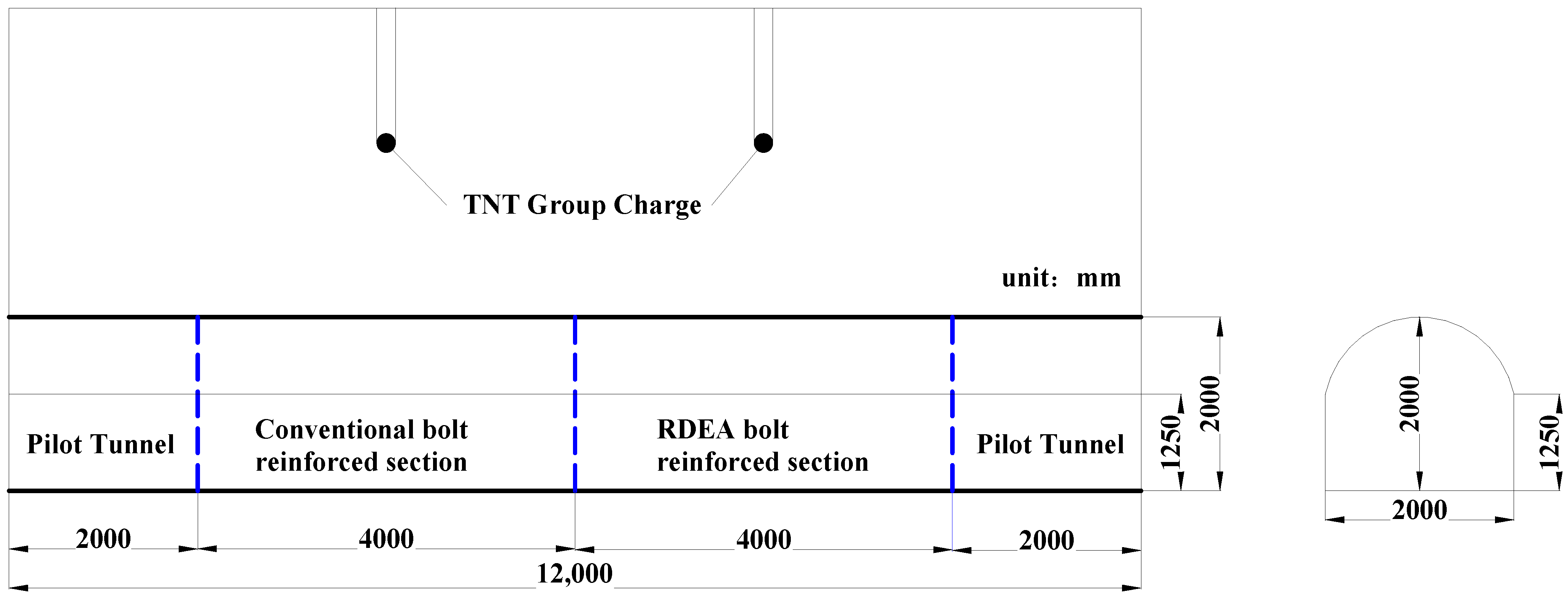
The field test was carried out by excavating a test cavern in a loess terrace, with a single tunnel selected. The shape of the test cavern was a straight wall arch, with a span of 2.0 m and a height of 2.0 m (wall height 1.25 m, arch height 0.75 m). The test cavern was divided into two test sections, from inside to outside, namely, the RDEA-bolt-reinforcement section and the conventional steel-bolt-reinforced test section (see
Figure 2 for details). Each test section is 4.0 m in length, and the total length of the front and rear pilot tunnels is 4 m. The total length of the entire test section is 12.0 m.
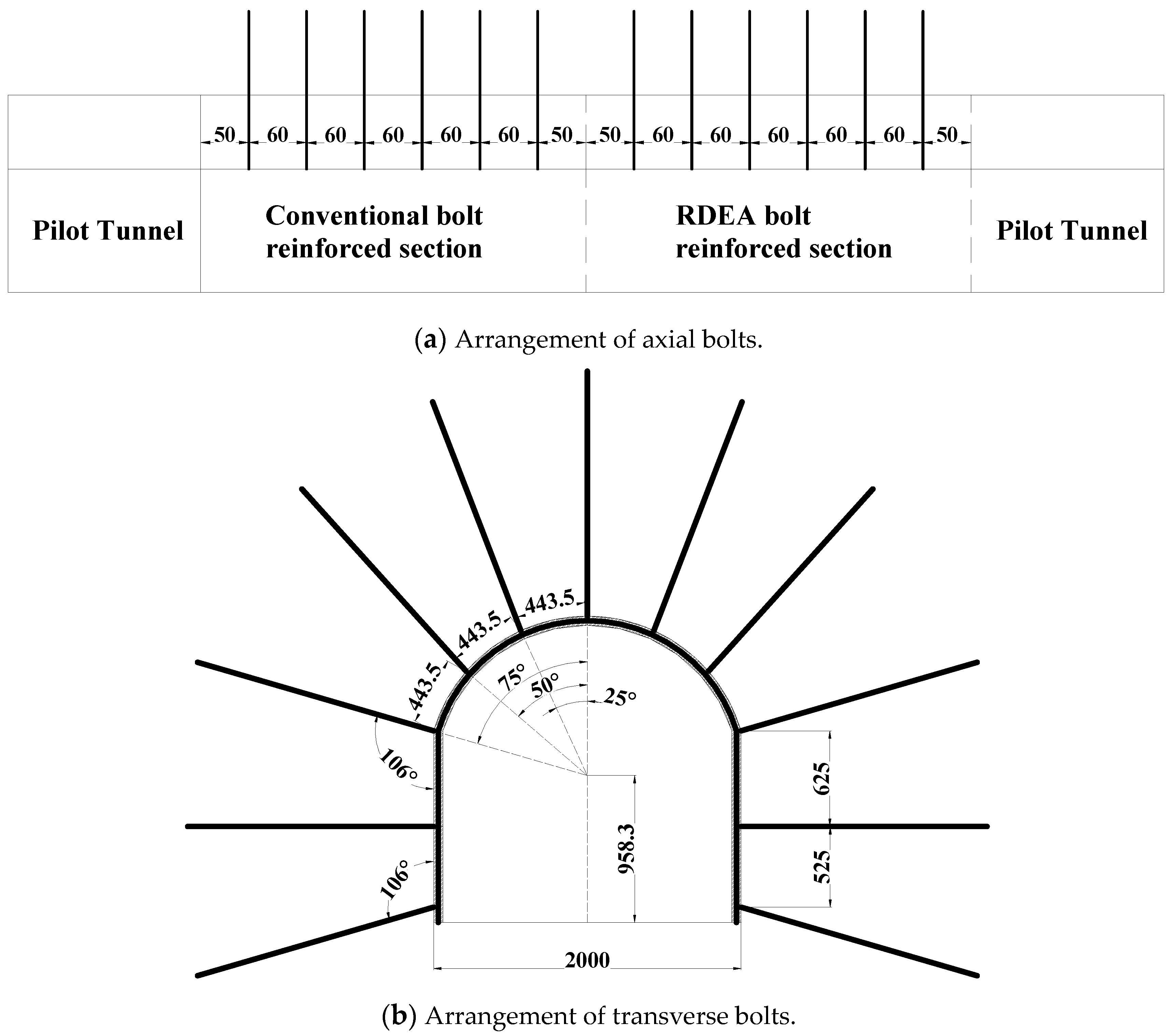
The arrangement of conventional steel-reinforced bolts and RDEA bolts was the same, with an axial distance of 0.6 m between bolts, and 50 cm left beforehand for each test section. There were 6 cross-sections arranged, with 11 bolts arranged in each cross-section. Only RDEA bolts were used in the arch part of the RDEA-bolt-reinforced section, while conventional steel-reinforced bolts were still used for the sidewall part. Specifically, one cross-section of the RDEA-bolt-reinforced section was reinforced with seven RDEA bolts and four conventional steel-reinforced bolts. The supporting surface layer was sprayed with C30 concrete with a thickness of 60 mm, and the specifications of the steel mesh were Φ6@80×80 mm. Cement slurry injection was used, and only the anchoring section of the RDEA bolt test section was injected with cement slurry. For specific anchor support parameters of the test cavern, see
Figure 3.
3.2. Test Condition Design
The field test was divided into three test conditions, and each test section was sequentially conducted from the inside to the outside for each condition. The blasting sequence was the RDEA-bolt-reinforced section followed by the conventional steel-bolt-reinforced section. After both test sections were blasted for the previous condition, the blasting work for the next condition would be carried out, and the blasting sequence would remain unchanged. In order to achieve the effect of comparative testing, the two test sections adopted the same charging scheme, and the single charging quantity was loaded in a step-by-step manner from small to large. The charging quantity, condition design, and proportionate burial depth design were detailed in
Table 1.
In order to ensure the effectiveness of the test, it is required that each explosive test must meet the “completely enclosed explosion” condition. The burial depth h of the charging in the test can be checked and calculated according to the following formula [
37]:
where
h is the burial depth in meters,
W is the charging quantity in kilograms, and
m is the filling coefficient, and when the condition of the completely enclosed explosion is met, m is taken as 1.65.
is the medium destruction yield coefficient, and
= 0.6 is used according to the local soil properties.
After calculation, the proportional burial depth
, that is, when the proportional burial depth
, the charging can meet the condition of a completely enclosed explosion. It can be seen from
Table 1 that the minimum proportional burial depth of the charging scheme for the field test is 1.62 m/kg
1/3, which can fully meet the requirements of a completely enclosed explosion test.
3.3. Measurement Point Arrangement
A total of six pressure sensors, eight displacement sensors, and six acceleration sensors were installed for the test.
- (1)
Pressure sensors
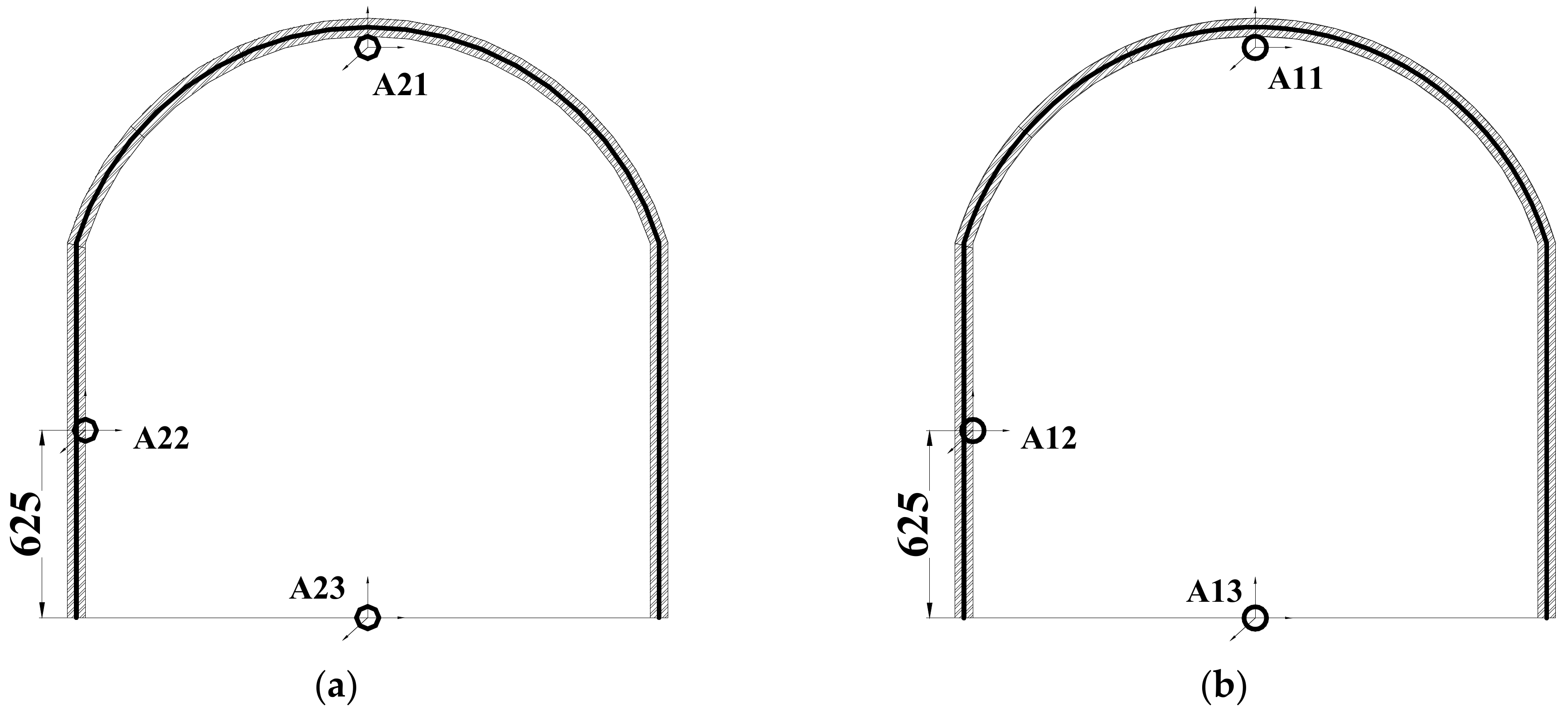
Three pressure sensors were installed between the center section of each test section, from the arch crown to the arch foot, to measure the vertical explosion pressure at the arch crown, half arch, and arch foot. The normal direction of the pressure sensing surface of all pressure sensors was vertical upward, and they were placed at a distance of 5 cm from the hole wall. Wet loess was used for backfill consolidation. The specific locations are shown in
Figure 4.
- (2)
Displacement sensors
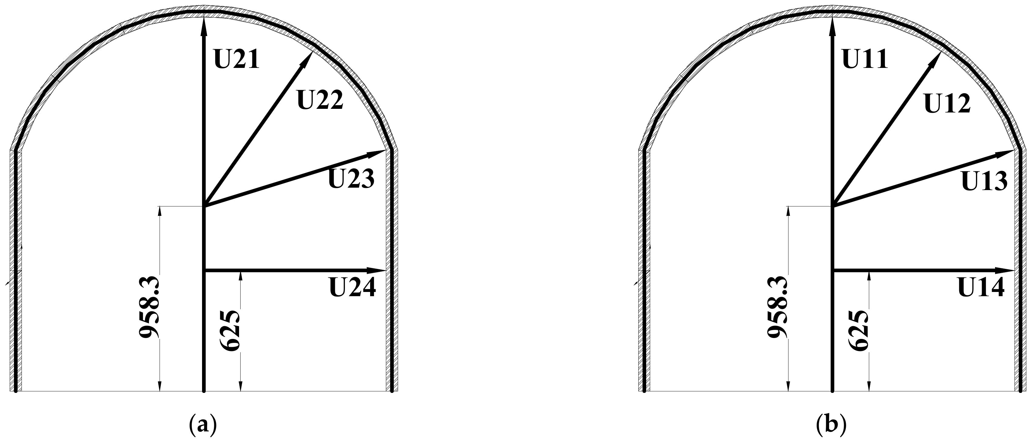
Wall displacement can reflect the macroscopic damage of the cavern under explosion loads and indicate the explosion resistance ability of different reinforcement methods. The KD2009T displacement sensor from Donghua was used in this test. The displacement sensors were mainly installed at the center of the arch crown, half arch waist, arch foot, and sidewall, measuring the relative displacement between different wall positions and the bottom plate as shown in
Figure 5. The maximum range of the displacement sensor at the arch crown and half arch waist positions is ±100 mm, and the range of the sensor is ±50 mm. The displacement sensors were installed on the center cross-section of the test section to study the deformation of the wall under explosive dynamic loads and the distribution of vertical damage in the cavern. The layout of the displacement sensors is shown in
Figure 6.
The displacement sensors were fixed on the support bracket welded before the test. The displacement bracket was made according to the dimensions after the two test sections were reinforced, with sufficient vertical and horizontal stiffness. The bracket was fixed to the ground through expansion bolts to avoid bracket oscillation or self-vibration caused by structural vibration during the test, which would affect the test results. The bracket used in the test was welded with channel steel, and the structure is shown in
Figure 5. Since this test used a group charge explosion at the top, which was a typical problem of local effects, the deformation was mainly concentrated on the arch crown and sidewalls, and the disturbance of the bottom plate is relatively small. The displacement sensor bracket was firmly fixed to the bottom plate, and the measured data are all the relative displacement between the different parts of the wall and the bottom plate.
- (3)
Acceleration sensors
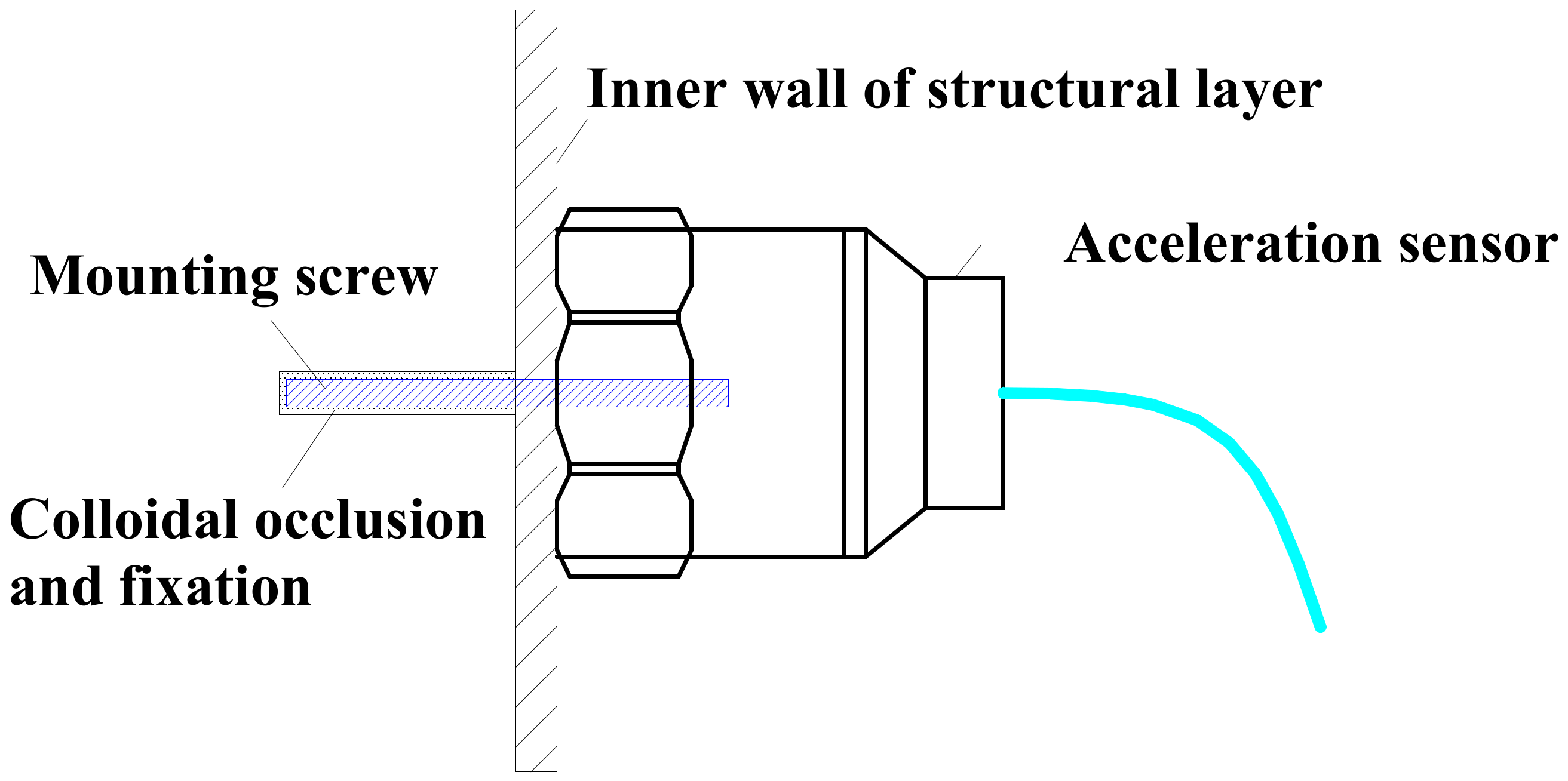
IEPE-type piezoelectric acceleration sensors produced by Donghua were used for this test, as shown in
Figure 7. The IEPE-type acceleration sensor has a built-in integrated circuit, which does not require an external signal amplifier. It directly outputs a recordable voltage signal with strong anti-interference ability.
The acceleration sensor was installed on the inner wall of the structural layer. First, a deep hole with a diameter of 2 mm and a depth of about 20 mm was drilled vertically to the wall surface at the installation position. The nut was anchored in the installation hole by structural adhesive, and the acceleration sensor was finally fixed on the mounting nut and bonded with structural adhesive, as shown in
Figure 8.
The wall acceleration sensors mainly measure the acceleration at the arch crown, sidewall center, and bottom plate of the central section of the test section below the detonation point. It studies the acceleration distribution of different parts of the test sections under the explosive load and analyzes the relationship between acceleration and macroscopic damage of the cavern. The axial direction of the acceleration sensor was perpendicular to the inner wall of the structure. The acceleration sensor at the bottom plate position was vertically installed on the bottom plate to measure the magnitude of the vertical acceleration in the axial direction of the bottom plate. The specific locations are shown in
Figure 9.
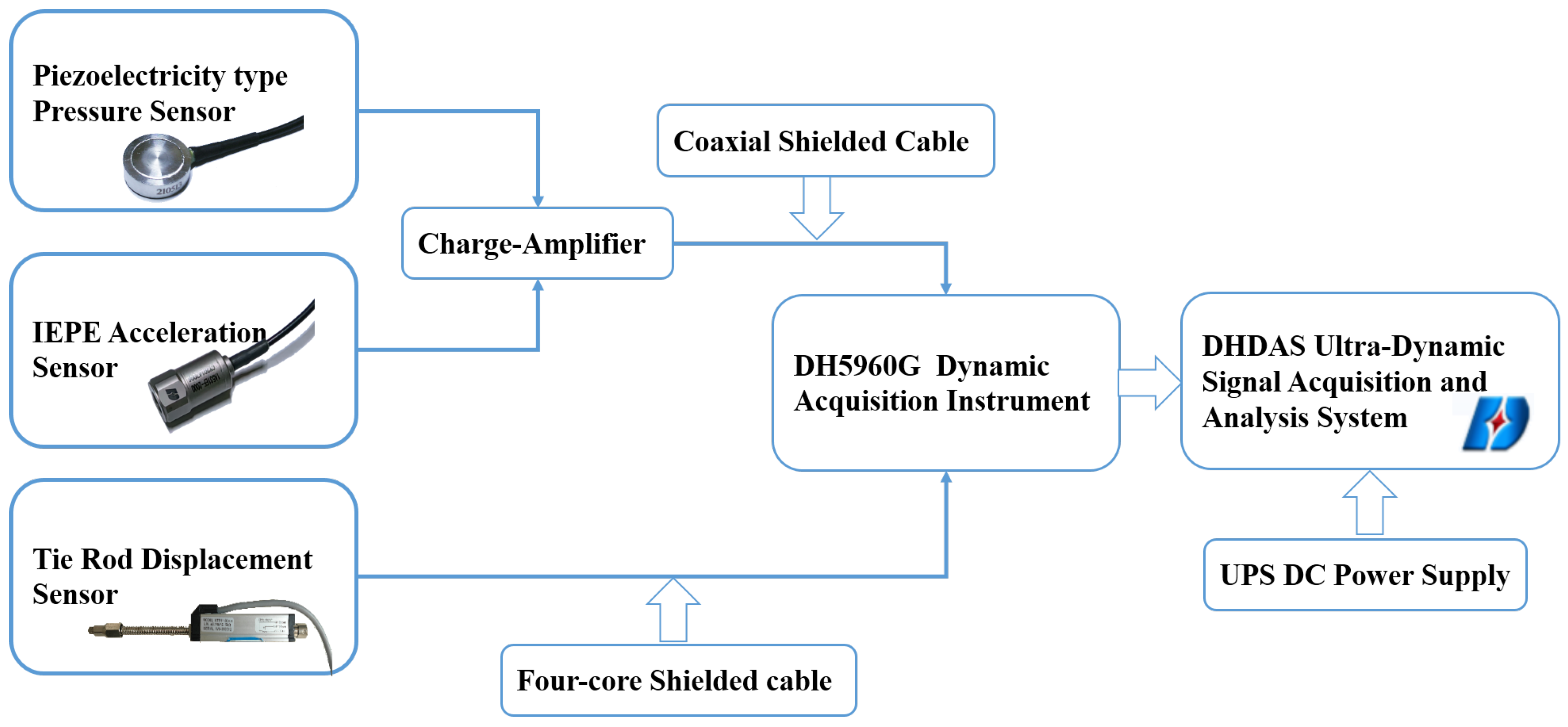
3.4. Measurement System
In this test, measurements were taken for explosive loads, wall displacement, and acceleration acting on the support structure. The macroscopic deformation and damage of each test section were also recorded in detail during the test. The measurement system mainly consisted of various types of sensors (including 6 pressure sensors, 8 displacement sensors, and 6 acceleration sensors), shielded cables (pressure and acceleration sensors are connected to the instrument through coaxial shielded cables, and displacement sensors are connected to the instrument through four-core shielded cables), charge amplifiers, DH5960G dynamic acquisition instrument and DHDAS ultra-dynamic signal acquisition and analysis system, and a measuring computer. During the test, UPS DC power was used to supply power to each acquisition equipment to avoid signal interference caused by unstable AC current. The schematic diagram of the measurement system is shown in
Figure 10.
The piezoelectric pressure sensors and IEPE acceleration sensors output voltage signals through charge amplifiers, and the pull-rod displacement sensors output voltage signals, which are collected in real time by the DH5960G ultra-high-speed dynamic acquisition instrument. The explosion load signal is usually at the millisecond level. To ensure that the signal characteristics are not lost, a sampling frequency of 1 MHz was selected. Due to the high sampling frequency and short sampling time of the explosion pressure time-history signal, manual control of signal acquisition is not feasible. Donghua Testing System provides four common triggering methods, including manual triggering, external triggering, signal triggering, and timing triggering. Among them, high-level triggering is a relatively simple and safe external triggering method that is commonly used. A signal wire is led out in the external triggering channel of the testing system, connected to a constant power supply, and the enameled wire at the front end is wound around the explosive package. After the explosion, the TNT explosive rapidly expands, simultaneously producing high-temperature and high-pressure blast products, causing the enameled wire to break and the circuit to disconnect, and the signal changes suddenly to the constant power supply voltage, triggering automatic acquisition. Although this automatic triggering method does not consider the time error during the process from ignition to explosive expansion causing the triggering wire to break, it is generally considered to be very short and will not significantly affect the measurement results. The test acquisition time was set to 200 ms, and a negative delay was used to ensure the integrity of the data signal. The negative delay was set to 20 ms.
As this test had two test sections and ordnance was detonated sequentially from the inside to the outside (that is, the RDEA-bolt-reinforced section was detonated first, followed by the conventional steel-bolt-reinforced section), so during the on-site measurement, measurement work for pressure, acceleration, and displacement could only be conducted on the detonated test section to minimize signal interference caused by too many wire connections.
5. Analysis of Test Results
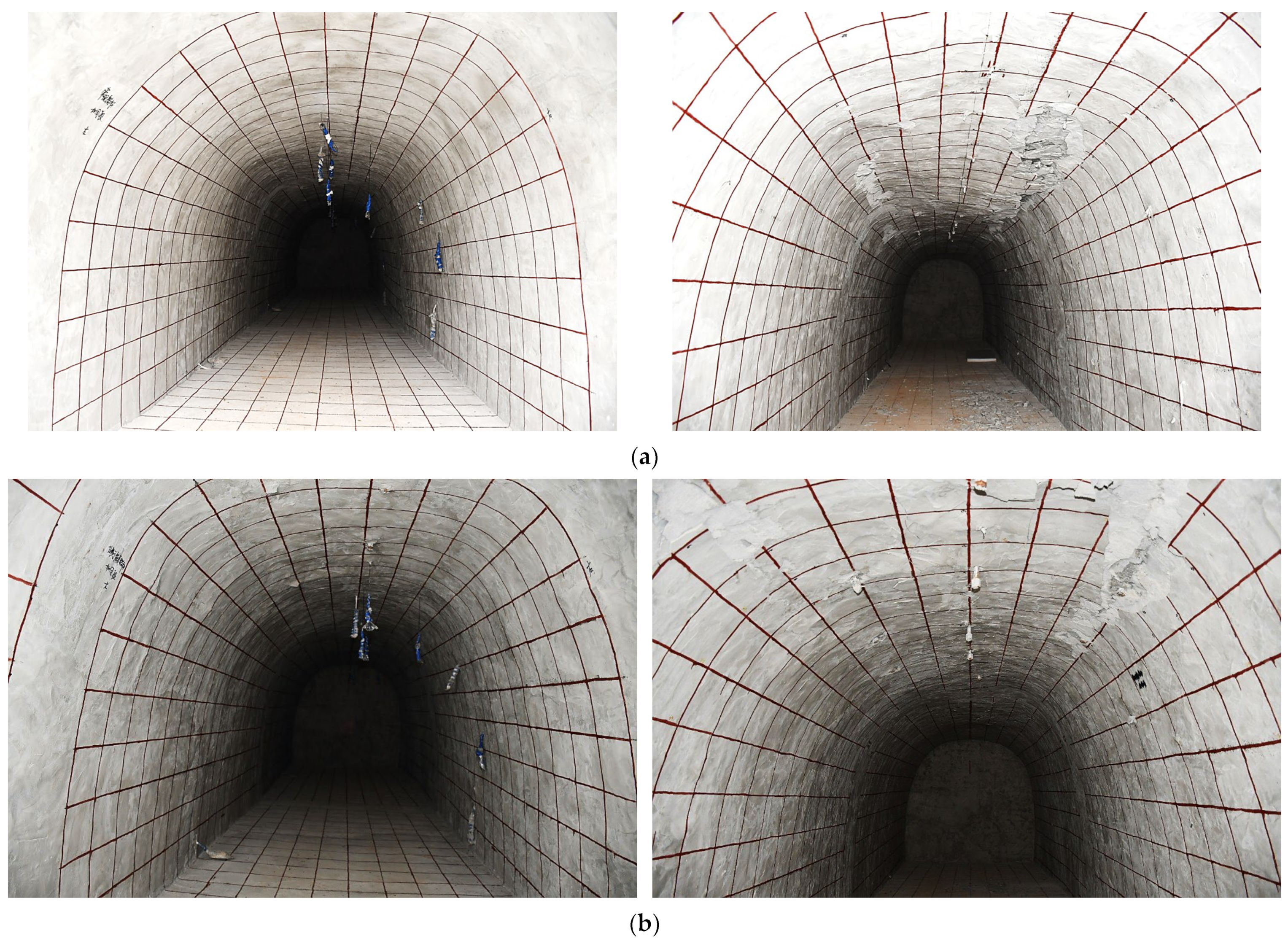
5.1. Macroscopic Analysis of Failure Patterns of the Test Section
The failure of the on-site test was mainly reflected in the failure of the sprayed layer. The overall thickness of the sprayed layer was 6 cm, which was far less than the axial length of the test section of 4 m. The sprayed layer belonged to a thin shell structure, which would be in a very unfavorable stress state when the explosive load was too large. The arch crown and 1/2 arch waist positions were most prone to stress concentration, leading to shear failure, delamination failure, and spalling of the sprayed layer. Therefore, for the sprayed layer or lining structure constructed inside the cavern, if the surrounding rock (soil) medium experiences significant deformation, it poses a great threat to the safety of the internal structure of the cavern. Therefore, the bolt structure type adopted in the protection project must have sufficient support stiffness, energy absorption characteristics, and sufficient deformation to better meet the needs of rock reinforcement in the protection project.
There were 2 m long pilot tunnel sections before and after the two test sections, and the unexcavated soil at the end provided good constraints for each test section, ensuring that each test section had equally effective boundary conditions and did not cause aggravated damage to the inlet of the test section. The overall damage effect of each test section is shown in
Figure 12.
As shown in
Figure 12a, after the third condition (W = 10 kg) test, the conventional steel-bolt-reinforced test section suffered serious damage, with the sprayed layer in the range from the arch crown to 1/2 arch waist deforming significantly vertically downward. There was serious delamination and shear failure on both sides of the 1/2 arch waist position, with large areas of the sprayed layer peeling off, exposing the mesh reinforcement and showing serious deformation and bending. The maximum length of the damaged area was measured to be 3.2 m, and the maximum width was 50 cm. As shown in
Figure 12b, the degree of damage to the RDEA-bolt-reinforced test section was far less than that of the conventional steel-bolt-reinforced test section, with only mild delamination failure and shear cracks appearing at the 1/2 arch waist position.
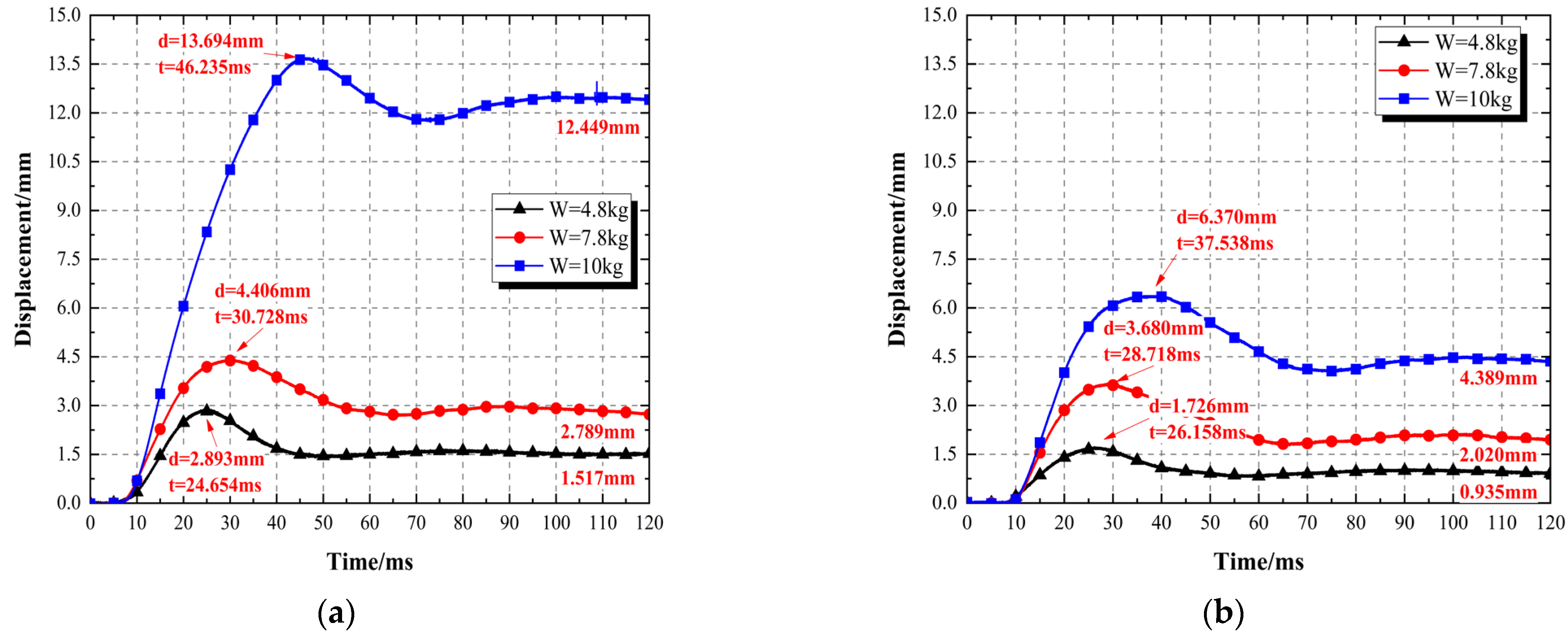
The displacement of the cavern wall directly reflects the deformation of the test section, which is the most direct and obvious response to the mechanical state and changes in the two test sections. It is also the most sufficient and effective parameter for analyzing the overall stability of the cavern. Due to the maximum deformation of the cavern crown under the explosion of the top cluster charges, the displacement of the cavern crown can best reflect the dynamic response of the two test sections under the explosion load of the three conditions. Therefore, this article selected the data of the crown displacement measurement point and analyzed it. The comparison chart of the crown displacement of the two test sections is shown in
Figure 13, and the statistical table of the peak and residual values of the crown displacement is given in
Table 2.
As shown in
Figure 13, the waveforms of the crown displacement measurement points of each test section were similar. Under the explosive load, the crown displacement rapidly increased to its maximum value, then rebounded slightly, and gradually tended to a stable residual value. As the explosive load gradually increased, the peak displacement and residual value of the crown displacement increased gradually. Compared to the two test sections under the second and third conditions, the peak and residual values of the crown displacement of the conventional steel-bolt-reinforced test section are higher than those of the RDEA-bolt-reinforced test section. Taking the third condition test with an explosive charge amount of W = 10 kg as an example, the peak displacement of the conventional steel-bolt-reinforced test section is 13.694 mm (2.15 times that of the RDEA-bolt-reinforced test section), and the RDEA-bolt-reinforced test section is 6.37 mm. This phenomenon corresponds to the macroscopic failure modes of the two test sections and also reflects that the blast resistance of the RDEA bolt is better than that of the conventional steel bolt. The exponential fitted relationships between the crown displacement and the proportional distance
of the RDEA-bolt-reinforced test section and conventional steel-bolt-reinforced test section under different conditions are, respectively, as follows:
In the equation:
d—the displacement of the arch crown, m;
W—the amount of explosive charge, kg;
R—the distance between the arch crown and the blast center, m.
The fitted Equations (2) and (3) indicated that there is a negative exponential relationship between the crown displacement and the proportional distance of each test section, and the peak displacement will decrease with the increase in the proportional distance. At the same time, it also indicates that when the reinforcement type of the cavern, the distance from the explosive center, and the amount of explosives are known, the peak displacement of the crown can be predicted by fitting the relationship equation.
As given in
Table 2, the total residual value of the crown displacement of the conventional steel-bolt-reinforced test section is 16.755 mm (2.28 times that of the total residual value of the crown displacement of the RDEA-bolt-reinforced test section) and that of the RDEA-bolt-reinforced test section is 7.344 mm. This indicated that the damage of the conventional steel-bolt-reinforced test section is more severe than that of the RDEA-bolt-reinforced test section.
Comparing the peak and residual values of the crown displacement of the two test sections under the third condition (W = 10 kg), it was found that the proportion of the rebound displacement of the conventional steel-bolt-reinforced test section to the peak displacement was only 9.09%, while that of the RDEA-bolt-reinforced test section is 31.1%. The proportion of the displacement rebound of each test section reflects the difference in blast resistance performance between the caverns. This also indicated that the blast resistance performance of the RDEA-bolt-reinforced test section is better in this test, and the RDEA bolt played a role in restoring part of the displacement during the test process due to its good anchoring performance, while the blast resistance performance of the conventional steel-bolt-reinforced test section is poor.
As shown in the displacement curve in
Figure 13, the crown displacement of the two test sections tended to stabilize at the 90 ms mark after reaching the peak values in the three condition tests, indicating that the rock deformation has shown a significant lag phenomenon under the conditions of explosive dynamic loading.
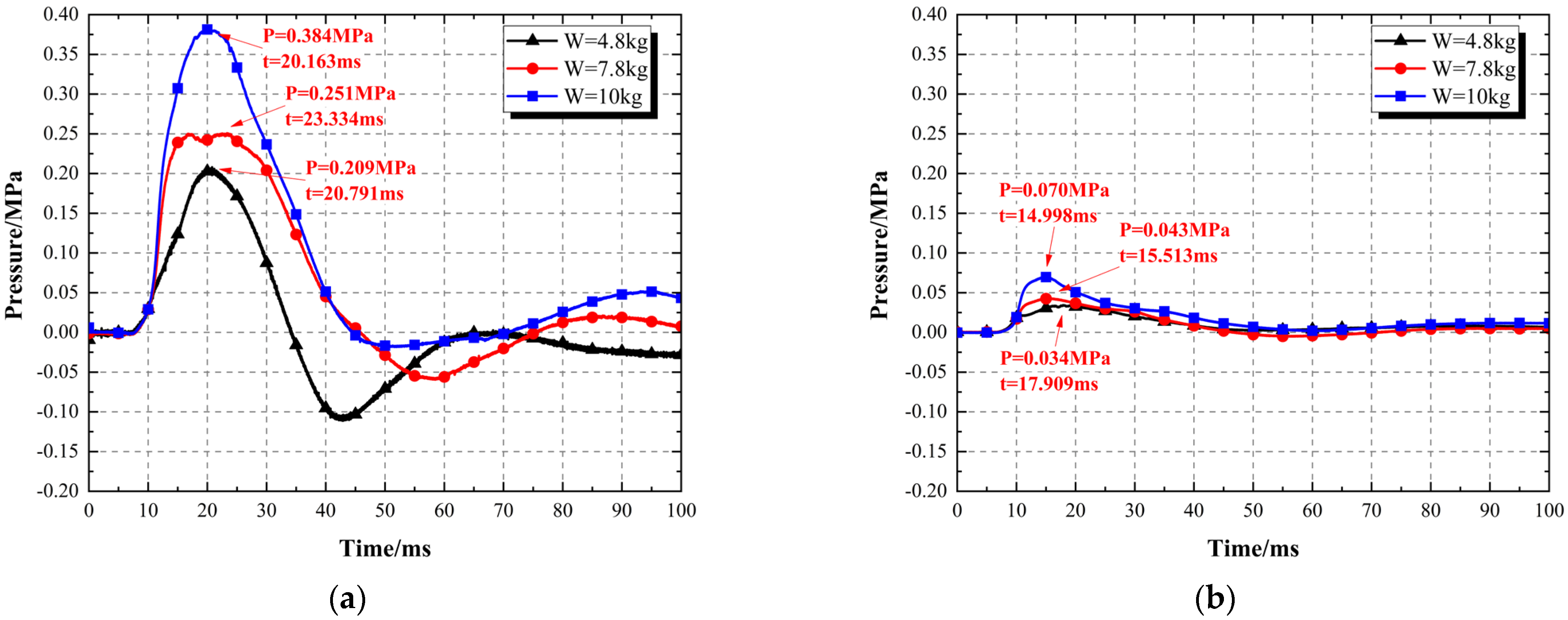
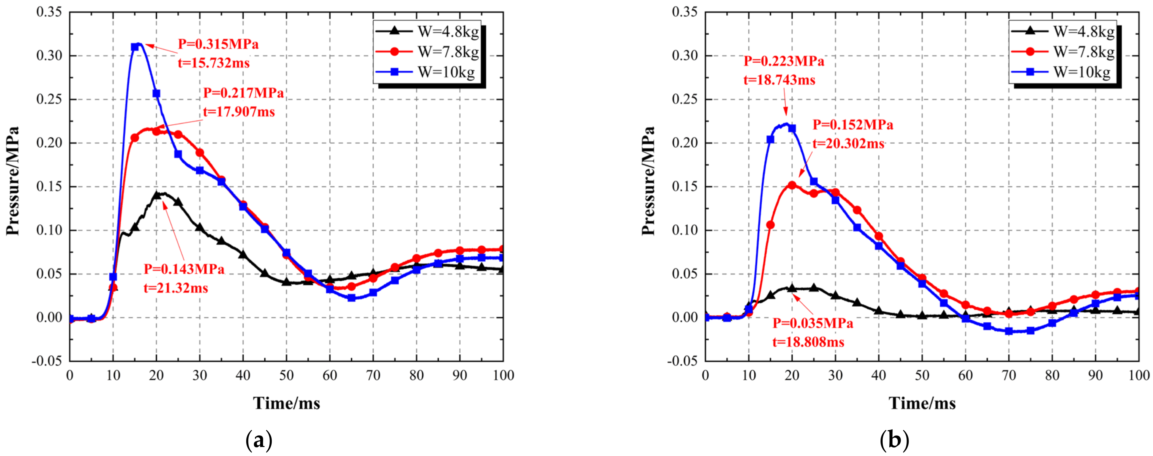
5.2. Explosion Pressure
The explosive pressure can reflect the explosive load acting on the anchored cavern soil medium. In this field test, three pressure sensors were installed at different positions of each test section, and the normal direction of each pressure sensor’s pressure-bearing surface is vertical, so the pressure measured is all in the vertical direction. This article focuses on the comparative analysis of the pressure measurement data of the crown, 1/2 arch waist, and arch foot positions. The vertical pressure comparison of these positions under different conditions is shown in
Figure 14,
Figure 15 and
Figure 16.
As shown in
Figure 14 and
Table 3, the stress peak value of the top of the cavern for the conventional steel-bolt-reinforced test section is higher than that of the RDEA-bolt-reinforced test section for each test condition: Taking the third condition test with an explosive charge amount of W = 10 kg as an example, the stress peak value at the top of the RDEA-bolt-reinforced test section is 0.131 MPa, while that of the conventional steel-bolt-reinforced test section is 0.556 MPa, which is approximately 4.24 times that of the RDEA-bolt-reinforced test section (the crown pressure of the RDEA-bolt-reinforced test section is 76.4% lower than that of the conventional steel-bolt-reinforced test section after the third condition test). This phenomenon reflects the good energy dissipation characteristics of the RDEA bolt compared to the conventional steel bolt. At the same time, it also indicated that the anchor type has a significant impact on the variation law of explosive loads in the anchoring area with different structural forms of anchor bolts. Compared with the conventional steel-bolt-reinforced test section, when the limit anchoring force of the conventional reinforced rebar anchor and the RDEA bolt is roughly equivalent, the weakening effect of the RDEA-bolt-reinforced test section on the explosive load is mainly due to the shear friction energy dissipation of internal No. 3 shear slid block on No. 4 internal threads under the action of explosive pressure, which can effectively attenuate the explosive load acting on the anchoring area and achieve energy absorption effect.
As shown in
Figure 14,
Figure 15 and
Figure 16, the vertical pressure waveforms of the crown, 1/2 arch waist, and arch foot positions of the two test sections are different, and the vertical pressure at each measurement point in the RDEA-bolt-reinforced test section is significantly lower than that in the conventional steel-bolt-reinforced test section. The waveforms of the pressure measurement points at the 1/2 arch waist and arch foot positions of both test sections are roughly similar, rapidly rising to the positive peak value, then rapidly falling to the negative peak value, and then oscillating slightly, but their peak values differ significantly.
The RDEA-bolt-reinforced test section exhibited a phenomenon in which the vertical pressure at the arch foot position is slightly higher than that at the crown position in all three test conditions. This is mainly because the sidewall position is reinforced by conventional steel bolts, which have a greater wave impedance of surrounding rock compared to RDEA bolts. Additionally, due to the diversion effect of the cavern cavity, part of the load borne by the arch was transferred to the adjacent sidewall rock mass, resulting in stress concentration at the arch foot position.
The vertical pressure from the crown to the arch foot position of the conventional steel-bolt-reinforced test section increases as the proportional distance decreases in all three test conditions. This is mainly because the conventional steel-bolt-reinforced test section has a consistent overall reinforcement form, which results in a higher wave impedance of the surrounding rock of the cavern, slow decay of explosive stress, and larger vertical pressure than that of the RDEA-bolt-reinforced test section.
5.3. The Acceleration of the Cave Wall
The cavern wall acceleration can reflect the speed and stability of the surrounding rock vibration. Excessive acceleration indicates that the rock vibration is too fast, which can weaken the stability of the cavern. Therefore, it is necessary to measure the cavern wall acceleration. Three acceleration measurement points were installed in the center cross-section of each test section, located at the crown, sidewall center, and bottom plate, as shown in
Figure 9. The waveform of the acceleration measurement points of each test section under the three test conditions is shown in
Figure 17, and the peak accelerations at each measurement point of the two test sections under different conditions are detailed in
Table 4.
As given in
Table 4, as the explosive charge amount increases from the first test condition to the third, both test sections exhibit the largest acceleration at the arch crown position, followed by the sidewall center position, and the bottom plate has the smallest acceleration. The reason for this phenomenon was that the stress waves generated by the explosion propagate downward, and the main direction of the explosive pressure is downward. Additionally, the acceleration of the bottom plate was affected by diffraction as it passes through the cavern and interacts with the surrounding rock, resulting in a decrease in the strength of the explosive stress wave as it propagates downward. Therefore, the acceleration at the arch crown and sidewall center positions was relatively larger, while the bottom plate acceleration was relatively smaller.
The peak acceleration at the arch crown position of both test sections is positive, and in all three test conditions, the conventional steel-bolt-reinforced test section exhibited larger acceleration at the arch crown position than the RDEA-bolt-reinforced test section, with the arch crown acceleration of the conventional steel-bolt-reinforced test section in the third test condition being approximately 1.35 times that of the RDEA-bolt-reinforced test section. The main reason for the larger acceleration at the arch crown position of the conventional steel-bolt-reinforced test section was that its injection method was full-length bonding, which made the particles of the surrounding rock at the arch crown more firmly bonded and the integrity stronger, resulting in a larger explosive pressure acting on the conventional steel-bolt-reinforced test section compared to the RDEA-bolt-reinforced test section. Additionally, the RDEA bolt is a free energy-absorbing anchor with built-in elastic elements and an ungrouted free section near the cavern wall position. Its axial direction coincided exactly with the propagation direction of the arch crown stress wave and can effectively attenuate the energy of the explosive stress wave, thus resulting in a smaller arch crown acceleration than that of the conventional steel-bolt-reinforced test section.
The bottom plate acceleration also exhibited the phenomenon of the conventional steel-bolt-reinforced test section having a larger acceleration than the RDEA-bolt-reinforced test section. The reason for this may be that the arch crown acceleration of the conventional steel-bolt-reinforced test section was larger than that of the RDEA-bolt-reinforced test section, and the energy of the explosive stress wave transmitted to the arch crown of the conventional steelbolt-reinforced test section was also larger than that of the RDEA-bolt-reinforced test section. Therefore, after attenuation and diffraction during propagation around the cavern, the energy reaching the bottom plate is also larger in the conventional steel-bolt-reinforced test section, resulting in a relatively larger bottom plate acceleration.
The sidewall positions of both test sections are reinforced with conventional steel bolts with full-length grouting, and the horizontal arrangement of the bolts caused them to be oriented more vertically with respect to the downward-propagating explosive stress wave, enabling the surrounding rock to effectively resist the impact of the explosive pressure. However, due to the different reinforcement methods applied to the arch section of the two test sections, the RDEA bolt can partially weaken or alleviate the explosive pressure, resulting in a lower explosive pressure acting on the sidewall position of the RDEA-bolt-reinforced test section than that of the conventional steel-bolt-reinforced test section. Therefore, the sidewall center acceleration of the RDEA-bolt-reinforced test section is slightly smaller than that of the conventional steel-bolt-reinforced test section.
6. Conclusions
The macroscopic deformation and the measurement data analysis of each test section in this experiment clearly indicated the superiority of RDEA bolts compared to traditional steel bolts. Not only did it reflect better anti-blast reinforcement effects on the cavern structure, but it also exhibited energy-absorbing characteristics and partial displacement recovery properties. RDEA bolts not only achieve a weakening effect on the explosive load but also provide good anti-blast deformation recovery capability after reinforcement, demonstrating excellent potential applications.
Under the same loading conditions, the total residual displacement of the arch crown of the conventional steel-bolt-reinforced test section is 56.2% greater than that of the RDEA-bolt-reinforced test section, which corresponds well with the macroscopic failure phenomenon of the cavern. This indicated that the support effect of the RDEA bolt was superior to that of the conventional steel bolt and has a significant effect.
When the proportional distance is 0.93 m/kg1/3, the RDEA-bolt-reinforced test section exhibited a 76.4% smaller explosive pressure at the arch crown than the conventional steel-bolt-reinforced test section. This indicated that the energy-absorbing characteristics of the RDEA bolt are excellent and can effectively attenuate the effect of the explosive load.
The maximum acceleration of both test sections was located at the arch crown position, with the minimum acceleration at the bottom plate position. However, the conventional steel-bolt-reinforced test section exhibited a relatively larger acceleration at both the arch crown and bottom plate positions, indicating that the full-length bonding bolt is not as effective as the RDEA bolt in reducing the acceleration of the arch crown and the bottom plate in the test section.


