Abstract
We present a specific subwavelength-cavity high-gain circularly polarized ultra-thin antenna made of planar metamaterials. The antenna is designed to operate at 2.80 GHz with a fixed thickness of approximately 1/6 of the operating wavelength in free space. The asymmetric unit cells of the metamaterial antenna exhibit two characteristics, namely, negative permeability and polarization selection. A linear-polarization micro-strip patch, which can realize circular polarization without a complicated feeding network, is embedded in the cavity as a feed. The circular polarization mode of the antenna can be changed by simply rotating the planar metamaterial horizontally. Simulations and experiments conducted on this antenna yielded results that are in good agreement with each other. This new subwavelength planar antenna can have potentially important applications in communication, early warning systems, and radio observation.
1. Introduction
Antennas play an important role in wireless communication systems. They generally include linearly polarized and circularly polarized antennas. Compared to linearly polarized antennas, circularly polarized antennas possess several unique advantages in the harsh electromagnetic environment [1,2,3,4,5]. For example, circularly polarized antennas have a stronger anti-interference ability and can receive radio signals of arbitrary polarizations including linearly and circularly polarized radio signals. Therefore, they have been widely used in satellite communication, early warning monitoring, radio observation, etc. [3,4,5,6]. To realize long-distance transmission and high-precision radio observation, an antenna must radiate and receive electromagnetic waves in one or more specific directions. The demand for high-gain antennas has increased significantly [7,8,9,10]. Otherwise, the miniaturization of antennas has also been an important topic in engineering many types of high-quality modern equipment, including unmanned aerial vehicles, communication satellites, and advanced spaceborne radio detectors. Therefore, designing high-gain circularly polarized antennas has become an essential research topic.
The traditional high-gain circularly polarized antennas include parabolic antennas, horn antennas, waveguide slot antennas, lens antennas, etc. [11,12,13,14]. Even though these antennas provide high-gain circular polarization, most of them suffer from disadvantages, such as large size, difficult assembly, and poor flexibility. In recent years, micro-strip antennas have been widely studied because of their small size, low profile, easy integration, and good flexibility [15,16]. Array micro-strip antennas are also widely used to obtain a high-gain circular polarization [17,18,19,20,21]. However, designing an array antenna is a complex process because of the complicated feeding networks that are required to generate both a circularly polarized behavior and a high gain; in fact, such networks lead to low efficiency in high-gain antennas. Therefore, their application is restricted to only certain fields.
Metamaterials have unique electromagnetic properties compared to natural materials [22,23,24,25]; therefore, they have many important applications, including sensing and diagnostics, biomedicines, telecommunications, absorbers, measurements, etc. [26,27,28,29,30,31,32,33,34,35]. Therefore, metamaterial antennas are more advantageous than their conventional counterparts [24,25,36,37]. Metamaterials include double- and single-negative metamaterials (SNMs) [36,38]. SNMs include epsilon-negative metamaterials (ENMs) with negative permittivities and mu-negative metamaterials (MNMs) with negative permeabilities. Perfect ENMs and MNMs can be used as electric and magnetic mirrors, respectively. The reflection phase of perfect ENMs is π, while that of perfect MNMs is 0. A cavity metamaterial antenna, which is generally composed of a partially reflective surface (PRS), a resonant cavity, and a reflector, can be used to realize high-gain performance. Metals are a type of natural ENMs, the reflection phase of a smooth metal surface is close to π, and the minimum thickness of a cavity antenna composed of a smooth metal surface is half the resonant wavelength [39,40]. However, when made of MNMs, which are also called artificial magnetic conductors, the thickness of a cavity antenna can be equal to or less than 1/4 of the resonant wavelength [41,42,43,44]. Thus, new ultra-thin-cavity MNM antennas are attracting significant attention. Based on analysis and research on cavity antennas [40,44,45,46], a high-gain circularly polarized antenna is presented in this paper. We have designed a subwavelength planar MNM antenna with an asymmetric microstructure such that the PRS composed of the MNM units has dual characteristics of a negative permeability response and circular polarization selection. These types of antennas have the advantages of high-gain, ultra-thinness, good circular polarization radiation, simple feed network, and convenience of assembly.
In the next section, we describe the design of a high-gain circularly polarized MNM antenna with a simple linearly polarized patch source. All the simulations were performed using CST Studio Suite software. The metamaterial antenna was machined and its radiation performance was measured in a microwave anechoic chamber. Finally, the last section includes some conclusions.
2. Simulations and Experimental Measurements
In this study, we investigated a circularly polarized subwavelength cavity metamaterial antenna made of an MNM operating in GHz range. Figure 1 shows a three-dimensional schematic of the proposed antenna operating at 2.80 GHz. The metamaterial antenna consisted of three layers. The top layer was an MNM-PRS reflector composed of a periodic array of metallic crosses and patches on both surfaces of a 1.524 mm thick dielectric Rogers 4003C substrate (Rogers Corporation, Chandler, AZ, USA). Copper, with an electrical conductivity of 5.7 × 10⁷ S/m, was the selected metal. The MNM-PRS reflector has the characteristics of high reflection and low transmission. The biggest difference between the MNM-PRS reflector and the smooth metal reflector is that the former has a tunable reflection phase from 0° to 360°. The MNM-PRS reflector as a reflection plate for the cavity structure can reduce the thickness of the cavity. The middle layer was an air-filled subwavelength cavity. The bottom layer was a 1.524 mm thick dielectric (Rogers 4003c) substrate covered with a metallic patch feed on the upper face and a metallic ground plane acting as a perfect electric conductor (PEC) reflector on the other face; a single metallic patch was used as a radiation source on the top surface and a 50 Ω input port was provided on the opposite side. The electromagnetic signal radiated by the metal patch feed is reflected in the MNM-PRS reflector and metal ground plane. Multiple reflected electromagnetic waves propagate in the air-filled subwavelength cavity. When the thickness of the cavity meets certain conditions, the standing wave formed by multiple reflections can achieve resonance enhancement. High-directional electromagnetic signals can be radiated through the MNM-PRS reflector.
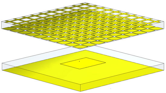
Figure 1.
Schematic of the 3D structure of the proposed antenna.
To calculate the radiation capability of the cavity structure, the resonant cavity antenna was simplified as shown in Figure 2. The proposed cavity was analyzed using both the reflection and transmission coefficients of the superstrate, as well as the reflection coefficient of the ground plane. The governing equations for a normally incident wave are given by [1,47]:
where is the phase between the ground plane and superstrate; n indicates the repetition number of the reflection wave inside the cavity; π is the refection phase of the ground; and R and T are the reflection and transmission coefficients, respectively, of the superstrate. In addition, the subscripts for R and T denote the polarization of the fields and describe the field transition of reflection and transmission. For example, Txy indicates the amount of field conversion from y-polarization to x-polarization for transmission coefficients passing through the superstrate. When x-polarization was excited in the cavity, the initial value of b1 was set to 0. However, a1 would become zero when the y-polarization was excited. Equations (5) and (6) show that the electric field strength of the cavity radiation can be calculated using R, T, and the thickness of the cavity.
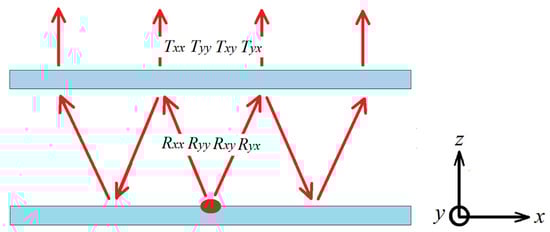
Figure 2.
Multiple reflections and transmissions between the MNM-PRS and ground plane.
The axial ratio (AR) is the ratio of mutually orthogonal components of an E-field and is often used for antennas, where the desired polarization is circular. AR is calculated using Equations (5) and (6) and is given by the references [1,47]:
where . From Equations (5)–(7), it can be seen that the AR of the electromagnetic waves radiated from the cavity can be calculated from R, T, and the thickness of the cavity.
First, we studied the reflection properties of an MNM-PRS unit cell. Figure 3 shows the structure of a square MNM-PRS unit, whose side length (p) was 24 mm and thickness (h) was 5 mm. The side length (l) of the square metallic patch was 14 mm; the width (w) of the metallic cross was 22.6 mm, and the side length of the corner cut (q) of the square metallic patch was 1.60 mm. To obtain R and T of the superstrate, the plane waves were illuminated from wave port 1 with x- or y-polarization to wave port 2, as shown in Figure 3. Additionally, all the lateral sides of the unit cell were enclosed with a periodic boundary condition (PBC), and all the simulations were performed using CST Studio Suite software, where CST Studio Suite is a high-performance 3D EM analysis software package for designing, analyzing, and optimizing electromagnetic (EM) components and systems.
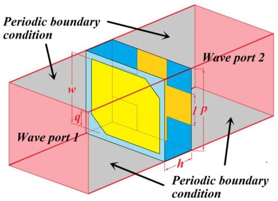
Figure 3.
The geometry of a unit cell and its boundary conditions; the electromagnetic waves are incident on port 1 and traverse to port 2.
Next, we calculated the amplitudes and phase values of Txx, Tyy, Txy, Tyx, Rxx, Ryy, Rxy, and Ryx for the MNM-PRS unit cells at different polarizations. Figure 4a shows the simulated MNM-PRS reflection and transmission coefficients. The transmission of this structure is mainly in the same polarization mode (Txx, Tyy). The transmission coefficient is greater than 0.6 from 2.40 GHz to 3.20 GHz, with its maximum value being near 2.75 GHz. The values of transmission coefficients with different polarizations (Txy, Tyx) are relatively small, less than 0.1 between 2.40 GHz and 3.20 GHz. The reflection of this structure is mainly in the same polarization mode (Rxx, Ryy). The reflection coefficient ranges from 0.7 to 0.8 in the range of 2.40 GHz to 3.20 GHz, with a minimum value of nearly 2.75 GHz. The values of reflection coefficients of different polarizations (Rxy, Ryx) are relatively small, less than 0.2 between 2.40 GHz and 3.20 GHz. Figure 4b shows the simulated reflection and transmission phases. In the frequency range of 2.40 GHz to 3.20 GHz, the transmission and reflection phases gradually decrease as the frequency increases. The same polarization reflection phase and transmission phase overlap at about 2.80 GHz. The values and changes of reflection and transmission phases with different polarizations are similar. Based on R and T values, the effective refractive index and impedance of the unit cell were calculated, from which µeff and εeff of the MNM-PRS unit cell can be calculated, as shown in Figure 4. In the figure, the red and black lines denote the real parts of µeff and εeff, respectively, while the magenta and blue lines denote the imaginary parts of µeff and εeff, respectively. It can be seen that the real part of µeff was negative, while that of εeff was positive over 2.68 GHz, and the former was minimal when near 2.80 GHz. These results indicate that the structure behaved like an MNM at 2.80 GHz. Using Equations (5) and (6), the values of the electric field strength for different polarizations were calculated, and the AR of the electromagnetic waves that radiated from the cavity could be obtained using Equation (7). The simulated boresight AR of the MNM-PRS cavity is plotted as a function of the frequency in Figure 4d. The AR of the antenna gradually decreases when increasing the frequency from 2.70 GHz to 2.80 GHz and increases with the frequency changing from 2.80 GHz to 2.90 GHz. The minimum AR was 1.02 at 2.80 GHz. Therefore, using this microstructure, a circularly polarized electromagnetic wave could be obtained from a linearly polarized electromagnetic wave, as shown in Figure 5. This structure can achieve low transmittance at a frequency of 2.80 GHz and can partially transmit resonant electromagnetic waves. Therefore, if the structure is periodically arranged and separated by a distance and combined with a metal plate, a resonance-enhanced FP cavity structure can be formed. If a linearly polarized radiation source is placed inside the cavity, the new antenna will have a high performance of radiation enhancement and circular polarization conversion.
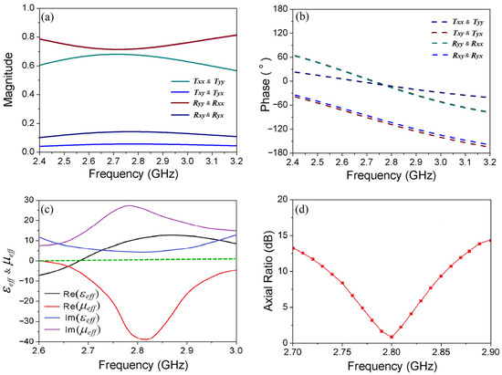
Figure 4.
(a) Simulated MNM-PRS reflection and transmission coefficients; (b) simulated reflection and transmission phases; (c) effective permeability (µeff) and permittivity (εeff) of the MNM-PRS unit cell, where the red and black lines denote the real parts of µeff and εeff, respectively, and the magenta and blue lines denote the imaginary parts of µeff and εeff, respectively; the green dashed line denotes zero effective permittivity or permeability; (d) simulated boresight axial ratios (ARs) for the proposed structure.
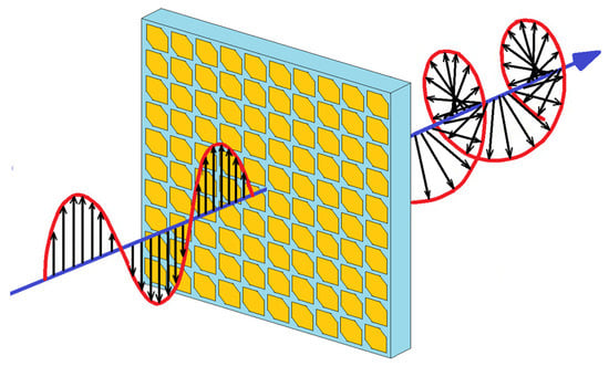
Figure 5.
Circular polarization behavior of the MNM-PRS.
Using the proposed MNM-PRS unit cell, n × n perfect metallic meshes and square patches with a pair of truncated corners were patterned on the top and bottom surfaces of the substrate to form an MNM-PRS layer. We studied a subwavelength cavity antenna using MNM metamaterials with antenna dimensions of 240 × 240 × 21 mm3. The thickness of the subwavelength air-filled cavity was 18 mm, which was approximately one-sixth of the operating wavelength of 107.1 mm. The radiation source was a simple, linearly polarized patch antenna.. We could perform a full-scale modeling of the antenna in the microwaves and RF/Optical Antenna module, and all material electromagnetic parameters came from the material library of the software. Appropriate parameter settings could ensure the accuracy of simulation results.
The simulated boresight ARs of the proposed antenna were plotted as a function of frequency in Figure 6a. The minimum AR was nearly 2.8 GHz, and this result agrees well with that observed in Figure 4d. At frequencies greater than 2.80 GHz, the AR of the antenna decreases. However, at frequencies below 2.80 GHz, the AR of the antenna increases. The metamaterial antenna exhibits the best circularly polarized properties at 2.80 GHz. The reflection coefficient of the proposed antenna is presented in Figure 6b, wherein the minimum value is –22.8 dB at 2.80 GHz. The antenna has a narrow working band at about 2.80 GHz, which proves that the antenna has narrow-band filtering characteristics. The reflection coefficient of the antenna exhibits narrowband characteristics and can achieve good antenna radiation at 2.80 GHz. This radiation frequency is the same as the circularly polarized frequency of the antenna, so the antenna can receive or radiate circularly polarized signals at 2.80 GHz. The radiation patterns simulated in two mutually orthogonal planes, namely, ϕ = 0 and 90°, are shown in Figure 7. The left-hand circular polarization (LHCP) boresight realized a gain of 13.70 dBi, while the right-hand circular polarization (RHCP) boresight realized a gain of –9.58 dBi at the same frequency of 2.80 GHz. The cross-polarization level was 23.29 dB. In two mutually orthogonal planes and circular polarization, radiation patterns have high directionality. The metamaterial plate and the metal plate constitute a subwavelength cavity structure. The weak directivity signal radiated by the radiation patch is resonance enhanced in the cavity, and finally, the high directivity electromagnetic signal is radiated through the metamaterial plate. The antenna’s ability to receive LHCP signals is much greater than RHCP signals, and the LHCP antenna has good directionality. This establishes that the proposed antenna is suitable for use as a high-gain LHCP antenna.
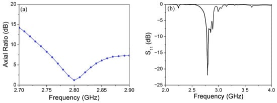
Figure 6.
Simulation results of the proposed antenna: (a) axial ratio (AR); (b) reflection coefficient (S11).
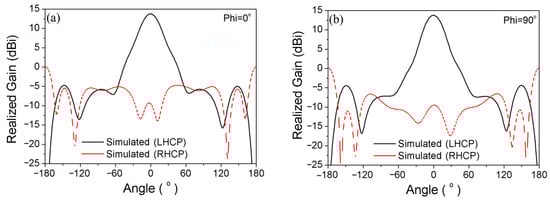
Figure 7.
Comparison of simulated radiation patterns of the proposed metamaterial antenna at 2.80 GHz on two mutually orthogonal planes: (a) ϕ = 0°; (b) ϕ = 90°.
Based on the simulation results, we exported CAD drawings and a subwavelength-cavity metamaterial antenna was fabricated using the etching technique. Figure 8 gives a positive photograph of the antenna. The antenna uses an etching technique, which is conducive to the integration of microwave devices such as amplifiers. The performance of the antenna was measured by a KEYSIGHT PNA N5224B network analyzer (10–43.5 GHz) in the standard microwave anechoic chamber with a range from 700 MHz to 40 GHz, as shown in Figure 8. The measured operating frequency of the antenna was 2.78 GHz, and the reflection coefficient S11 was less than –16.80 dB. As shown in Figure 9a, the measured and simulated results differed from each other in the operating frequencies, which could be attributed to the deviations in fabrication. The actual antenna has a narrow working band at 2.78 GHz, which proves that the antenna has narrow-band filtering properties. The radiation performance of the antenna was measured using a microwave anechoic chamber. The metamaterial antenna is placed on a test revolution plate that can rotate 360°, with the rotation plane parallel to the ground and the radiation surface of the antenna perpendicular to the ground. We placed a linearly polarized horn antenna that can rotate 360° in front of the metamaterial antenna, with the rotation plane perpendicular to the ground. The center of the metamaterial antenna coincided with the center of the horn antenna. It needed to connect the output and input ports of the vector network analyzer to the two antennas. The horn antenna radiated signals with different linear polarizations through rotating angles, and the axial ratio of the antenna could be measured by recording the signal strength received by the metamaterial antenna. By processing the measured data, we could obtain the radiation patterns of the metamaterial antenna. As shown in Figure 9b, the minimum measured value of AR was 1.36 at 2.78 GHz. The AR of the antenna first increased and then decreased with the increase of frequency in the range between 2.70 GHz and 2.78 GHz. The AR in the region from 2.78 GHz to 2.90 GHz antenna mainly shows an increasing trend. Figure 9c shows the realized gains on the ϕ = 0° plane. The realized gain in the LHCP boresight direction (black solid line) was 13.67 dBi at 2.78 GHz; the LHCP half power width was 32.1°; and the LHCP side-lobe level was –18.54 dB. On the other hand, the realized gain in the RHCP boresight direction (red dotted line) was –5.31 dBi at 2.78 GHz on the ϕ = 0° plane, and the cross-polarization level was 18.98 dB. Figure 9d shows the realized gains on the ϕ = 90° plane. The realized gain in the LHCP boresight direction (black solid line) was 13.67 dBi at 2.78 GHz; the LHCP half power width was 22.45°; and the LHCP side-lobe level was –14.19 dB. On the other hand, the realized gain in the RHCP boresight direction (red dotted line) was –5.54 dBi at 2.78 GHz on the ϕ = 90° plane, and the cross-polarization level was 19.21 dB. The measured results show that the antenna can receive LHCP signals and shield RHCP signals. The thickness of the subwavelength air-filled cavity was 18.0 mm, which was approximately one-sixth of the operating wavelength of 107.1 mm, and it is much smaller than that of traditional cavity antennas. For example, comparing the performance of the circularly polarized antenna with two cavities [46], the proposed metamaterial antenna of this work has only one subwavelength cavity and its MNM-PRS layer is composed of a circularly polarized unit cell. We used a subwavelength thickness cavity to enhance the radiation performance of the antenna and achieved a good conversion of linearly polarized signals to circularly polarized signals.
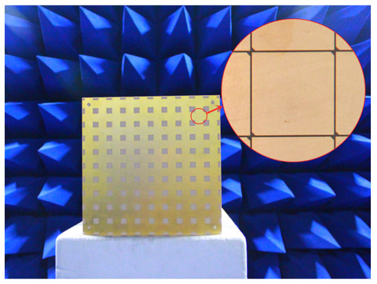
Figure 8.
Photograph of the proposed LHCP metamaterial antenna.
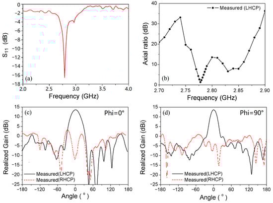
Figure 9.
Experimental measurements of the proposed LHCP metamaterial antenna: (a) reflection coefficient (S11); (b) measured axial ratio (AR). Comparison of LHCP and RHCP patterns of the LHCP metamaterial antenna at 2.80 GHz on two mutually orthogonal planes: (c) ϕ = 0°; (d) ϕ = 90°.
Next, the MNM-PRS plate was rotated horizontally by 90° to maintain the position of the PEC reflector and the radiation source fixed, as shown in Figure 10a. The position of the corner cut of the square metallic patch could produce a 90° deflection. Subsequently, the polarization selectivity of the MNM-PRS plate was reversed, and the LHCP antenna became an RHCP antenna. The measured parameters were as follows: The minimum AR, as shown in Figure 10b, was 1.16 at 2.78 GHz. The AR of the antenna first increased and then decreased with the increase of frequency in the range from 2.70 GHz to 2.78 GHz. However, the AR at a frequency range from 2.78 GHz to 2.90 GHz antenna first increased and then decreased. Figure 10c shows the realized gains on the ϕ = 0° plane. The realized gain in the RHCP boresight direction (black solid line) was 13.60 dBi; the RHCP half power width was 22.60°; and the LHCP side-lobe level was –17.68 dB on the ϕ = 0° plane. On the other hand, the realized gain in the LHCP boresight direction (red dotted line) was –9.78 dBi at 2.78 GHz on the ϕ = 0° plane and the cross-polarization level was 23.38 dB. Figure 10d shows the realized gains on the ϕ = 90° plane. The realized gain in the RHCP boresight direction (black solid line) was 13.60 dBi at 2.78 GHz; the RHCP half power width was 29.61°; and the LHCP side-lobe level was –20.84 dB. On the other hand, the realized gain in the LHCP boresight direction (red dotted line) was –9.23 dBi at 2.78 GHz in ϕ = 90° plane and the cross-polarization level was 22.83 dB. It can be observed that the antenna could receive the RHCP signals well and shields the LHCP signals. If an automatic rotating mechanism is added to the metamaterial plate, the antenna can easily realize the polarization change, obtain the multiplexing of the radiation aperture, and improve the utilization efficiency of the antenna. Overall, the experimental results agreed well with the theoretical values. Such theoretical and experimental results show that this kind of planar subwavelength-cavity metamaterial antenna is easy to be fabricated in the GHz region. Compared to the traditional high-gain circular polarization antennas, this metamaterial antenna has a low profile, is lightweight, and has a simple feed network. Thus, this kind of antenna can be used for many wireless communication types of equipment.
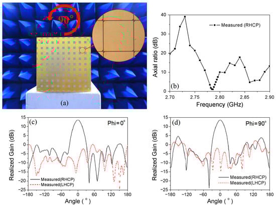
Figure 10.
(a) Photograph of the proposed RHCP metamaterial antenna; (b) measured axial ratio (AR) of the proposed RHCP metamaterial antenna. Comparison of the measured radiation patterns of the RHCP metamaterial antenna at 2.80 GHz on two mutually orthogonal planes: (c) ϕ = 0°; (d) ϕ = 90°.
3. Conclusions
In this study, a subwavelength-cavity circularly polarized antenna was proposed using artificial permeability-negative metamaterials that can convert linear polarization into circular polarization. This antenna also has the advantages of adjustable polarization and a high gain. Compared with conventional high-gain circularly polarized antennas, the proposed antenna achieves the desired performance with a much lower profile, simpler design, and easier integration. This cavity antenna has good narrowband characteristics to engineer high-quality filtering devices in compacted radio systems, which is also conducive to the miniaturization of the radio systems. Good agreement between the measured and theoretically predicted behaviors ensured the validity of our design and prediction method. Such metamaterial antennas can be utilized in communication systems, satellite antennas, and spaceborne radio detectors.
Author Contributions
Conceptualization, W.W., G.L. and G.D.; methodology, G.L. and G.D.; software, W.W., G.L. and C.D.; validation, W.W., G.L. and C.D.; formal analysis, W.W., G.L. and J.L.; investigation, W.W., G.L., C.D. and J.L.; resources, G.L. and G.D.; data curation, G.L. and G.D.; writing—original draft preparation, W.W. and G.L.; writing—review and editing, J.L., F.L. and G.D.; visualization, W.W. and G.L.; supervision, G.L. and G.D.; project administration, G.L. and G.D.; funding acquisition, G.L. and G.D. All authors have read and agreed to the published version of the manuscript.
Funding
This research was funded by the Natural Science Foundation of Shandong Province (Nos. ZR2019MA055 and ZR2020QA071).
Institutional Review Board Statement
Not applicable.
Informed Consent Statement
Not applicable.
Data Availability Statement
Not applicable.
Conflicts of Interest
The authors declare no conflict of interest.
References
- Balanis, C.A. Antenna Theory: Analysis and Design; Harper & Row: New York, NY, USA, 1982. [Google Scholar]
- Tong, K.F.; Wong, T.P. Circularly Polarized U-Slot Antenna. IEEE Trans. Antennas Propag. 2007, 55, 2382–2385. [Google Scholar] [CrossRef]
- Thi, T.N.; Hwang, K.C.; Kim, H.B. Dual-band circularly-polarised Spidron fractal microstrip patch antenna for Ku-band satellite communication applications. Electron. Lett. 2013, 49, 444–445. [Google Scholar]
- Wardle, J.F.C.; Homan, D.C. Theoretical Models for Producing Circularly Polarized Radiation in Extragalactic Radio Sources. Astrophys. Space Sci. 2003, 288, 143–153. [Google Scholar] [CrossRef]
- Akbar, P.R.; Tetuko, J.S.S.J.; Kuze, H. A novel circularly polarized synthetic aperture radar (CP-SAR) system onboard a spaceborne platform. Int. J. Remote Sens. 2010, 31, 1053–1060. [Google Scholar] [CrossRef]
- Kashihara, H.; Sumantyo, J.T.S.; Izumi, Y.; Ito, K.; Gao, S.; Namba, K. X-band Microstrip Array Antenna for UAV onboard Full Circularly Polarized Synthetic Aperture Radar. IEEE Trans. Antennas Propag. 2023, 71, 1943–1948. [Google Scholar] [CrossRef]
- Fender, R.; Rayner, D.; Norris, R.; Sault, R.J.; Pooley, G. Discovery of Circularly Polarized Radio Emission from SS 433. Astrophys. J. 2000, 530, 29–32. [Google Scholar] [CrossRef] [PubMed]
- Shnitkin, H. Joint STARS phased array radar antenna. IEEE Aerosp. Electron. Syst. Mag. 1994, 9, 34–40. [Google Scholar] [CrossRef]
- Lin, W.; Ziolkowski, R.W.; Baum, T.C. 28 GHz Compact Omni-Directional Circularly Polarized Antenna for Device-to-Device (D2D) Communications in Future 5G Systems. IEEE Trans. Antennas Propag. 2017, 65, 6904–6914. [Google Scholar] [CrossRef]
- Zhang, L.; Zhang, J.; He, Y.; Mao, C.; Li, W.; Wong, S.W.; Mei, P.; Gao, S. A single-layer 10–30 GHz reflectarray antenna for the Internet of Vehicles. IEEE Trans. Veh. Technol. 2022, 71, 1480–1490. [Google Scholar] [CrossRef]
- Chai, X.; Liu, B.; Yu, L.; Yu, S.; Wu, D.; Liu, L. Experiments on the dish verification antenna china for the SKA. Exp. Astron. 2016, 42, 301–317. [Google Scholar] [CrossRef]
- Yu, H.; Yu, J.; Yao, Y.; Liu, X.; Chen, X. Wideband circularly polarised horn antenna with large aspect ratio for terahertz applications. Electron. Lett. 2020, 55, 11–13. [Google Scholar] [CrossRef]
- Sze, J.Y.; Wong, K.L.; Huang, C.C. Coplanar waveguide-fed square slot antenna for broadband circularly polarized radiation. IEEE Trans. Antennas Propag. 2003, 51, 2141–2144. [Google Scholar] [CrossRef]
- Wu, X.; Eleftheriades, G.V.; van Deventer-Perkins, T.E. Design and characterization of single- and multiple-beam mm-wave circularly polarized substrate lens antennas for wireless communications. IEEE Trans. Microw. Theory Tech. 2001, 49, 431–441. [Google Scholar] [CrossRef]
- Sharma, P.; Gupta, K. Analysis and optimized design of single feed circularly polarized microstrip antennas. IEEE Trans. Antennas Propag. 1983, 31, 949–955. [Google Scholar] [CrossRef]
- Carver, K.; Mink, J. Microstrip antenna technology. IEEE Trans. Antennas Propag. 1981, 29, 2–24. [Google Scholar] [CrossRef]
- Khan, I.; Wu, Q.; Ullah, I.; Rahman, S.U.; Ullah, H.; Zhang, K. Designed circularly polarized two-port microstrip MIMO antenna for WLAN applications. Appl. Sci. 2022, 12, 1068. [Google Scholar] [CrossRef]
- Alibakhshikenari, M.; Virdee, B.S.; Limiti, E. Wideband planar array antenna based on SCRLH-TL for airborne synthetic aperture radar application. J. Electromagn. Waves Appl. 2018, 32, 1586–1599. [Google Scholar] [CrossRef]
- Gan, Z.; Tu, Z.H.; Xie, Z.M.; Chu, Q.X.; Yao, Y. Compact Wideband Circularly Polarized Microstrip Antenna Array for 45 GHz Application. IEEE Trans. Antennas Propag. 2018, 66, 6388–6392. [Google Scholar] [CrossRef]
- Jazi, M.N.; Azarmanesh, M.N. Design and implementation of circularly polarised microstrip antenna array using a new serial feed sequentially rotated technique. IEE Proc. Microw. Antennas Propag. 2006, 153, 133–140. [Google Scholar] [CrossRef]
- Verma, A.; Arrawatia, M.; Kumar, G. High Gain Wideband Circularly Polarized Microstrip Antenna Array. IEEE Trans. Antennas Propag. 2022, 70, 11183–11187. [Google Scholar] [CrossRef]
- Smith, D.R.; Pendry, J.B.; Wiltshire, M.C.K. Metamaterials and negative refractive index. Science 2004, 305, 788–792. [Google Scholar] [CrossRef]
- Schurig, D.; Mock, J.J.; Justice, B.J.; Cummer, S.A.; Pendry, J.B.; Starr, A.F.; Smith, D.R. Metamaterial electromagnetic cloak at microwave frequencies. Science 2006, 314, 977–980. [Google Scholar] [CrossRef]
- Veselago, V.G. The electro dynamics of substances with simultaneously negative values of µ and ε. Sov. Phys. Usp. 1968, 10, 509–514. [Google Scholar] [CrossRef]
- Shelby, R.A.; Smith, D.R.; Schultz, S. Experimental Verification of a Negative Index of Refraction. Science 2001, 292, 77–79. [Google Scholar] [CrossRef]
- Estakhri, N.M.; Edwards, B.; Engheta, N. Inverse-designed metastructures that solve equations. Science 2019, 363, 1333–1338. [Google Scholar] [CrossRef] [PubMed]
- Spada, L.L.; Vegni, L. Near-zero-index wires. Opt. Express 2017, 25, 23699–23708. [Google Scholar] [CrossRef] [PubMed]
- Greybush, N.J.; Pacheco-Peña, V.; Engheta, N.; Murray, C.B.; Kagan, C.R. Plasmonic Optical and Chiroptical Response of Self-Assembled Au Nanorod Equilateral Trimers. ACS Nano 2019, 13, 1617–1624. [Google Scholar] [CrossRef]
- Lalegani, Z.; Seyyed Ebrahimi, S.A.; Hamawandi, B.; Spada, L.L.; Batili, H.; Toprak, M.S. Targeted dielectric coating of silver nanoparticles with silica to manipulate optical properties for metasurface applications. Mater. Chem. Phys. 2022, 287, 126250. [Google Scholar] [CrossRef]
- Spada, L.L.; Vegni, L. Metamaterial-based wideband electromagnetic wave absorber. Optics express 2016, 24, 5763–5772. [Google Scholar] [CrossRef] [PubMed]
- Pacheco-Peña, V.; Beruete, M.; Rodríguez-Ulibarri, P.; Engheta, N. On the performance of an ENZ-based sensor using transmission line theory and effective medium approach. New J. Phys. 2019, 21, 043056. [Google Scholar] [CrossRef]
- Qin, F.; Ding, L.; Zhang, L.; Monticone, F.; Chum, C.C.; Deng, J.; Mei, S.; Li, Y.; Teng, J.; Hong, M.; et al. Hybrid bilayer plasmonic metasurface efficiently manipulates visible light. Sci. Adv. 2016, 2, e1501168. [Google Scholar] [CrossRef]
- Spada, L.L.; Spooner, C.; Haq, S.; Hao, Y. Curvilinear MetaSurfaces for Surface Wave Manipulation. Sci. Rep. 2019, 9, 3107. [Google Scholar] [CrossRef]
- Meher, P.R.; Behera, B.R.; Mishra, S.K. A compact circularly polarized cubic DRA with unit-step feed for Bluetooth/ISM/Wi-Fi/Wi-MAX applications. AEU-Int. J. Electron. Commun. 2021, 128, 153521. [Google Scholar] [CrossRef]
- Meher, P.R.; Behera, B.R.; Mishra, S.K.; Althuwayb, A.A. A chronological review of circularly polarized dielectric resonator antenna: Design and developments. Int. J. RF Microw. Comput. Aided Eng. 2021, 31, e22589. [Google Scholar] [CrossRef]
- Alù, A.; Engheta, N. Pairing an epsilon-negative slab with a mu-negative slab: Resonance, tunneling and transparency. IEEE Trans. Antennas Propag. 2003, 51, 2558–2571. [Google Scholar] [CrossRef]
- Zhong, X.; Xu, H.X.; Chen, L.; Hou, J.; Wang, H.; Li, W.; Shi, Y.; Shi, X. Metasurface-Assisted Broadband Circularly Polarized Folded Reflectarray Antenna. IEEE Trans. Antennas Propag. 2022, 70, 10465–10474. [Google Scholar] [CrossRef]
- Liu, Y.; Dai, Y.; Feng, Q.; Shan, Y.; Du, L.; Xia, Y.; Lu, G.; Liu, F.; Du, G.; Tian, C.; et al. Enhanced light-matter interactions in graphene-covered dielectric magnetic mirrors. Opt. Express 2017, 25, 30754–30763. [Google Scholar] [CrossRef]
- Akalin, T.; Danglot, J.; Vanbesien, O.; Lippens, D. A highly directive dipole antenna embedded in a Fabry-Perot type cavity. IEEE Microw. Wirel. Compon. Lett. 2017, 12, 48–50. [Google Scholar] [CrossRef]
- Ju, J.; Kim, D.; Lee, W.; Choi, J. Design Method of a Circularly-Polarized Antenna Using Fabry-Pérot Cavity Structure. ETRI J. 2011, 33, 163–168. [Google Scholar] [CrossRef]
- Wang, S.; Feresidis, A.P.; Goussetis, G.; Vardaxoglou, J.C. High-gain subwavelength resonant cavity antennas based on metamaterial ground planes. IEE Proc. Microw. Antennas Propag. 2006, 153, 1–6. [Google Scholar] [CrossRef]
- Zhou, L.; Li, H.; Qin, Y.; Wei, Z.; Chan, C.T. Directive emissions from subwavelength metamaterial-based cavities. Appl. Phys. Lett. 2005, 86, 48–147. [Google Scholar] [CrossRef]
- Ourir, A.; Lustrac, A.; Lourtioz, J.M. All-metamaterial-based subwavelength cavities (λ/60) for ultrathin directive antennas. Appl. Phys. Lett. 2006, 88, 084103. [Google Scholar] [CrossRef]
- Lu, G.; Wang, W.; Yan, F.; Diao, C.; Zhou, X.; Wu, Z.; Liu, F.; Sun, Y.; Du, G.; Chen, Y. Large area subwavelength cavity antenna with planar metamaterials. AIP Adv. 2019, 9, 025032. [Google Scholar] [CrossRef]
- Zhu, H.L.; Cheung, S.W.; Chung, K.L.; Yuk, T.I. Linear-to-Circular Polarization Conversion Using Metasurface. IEEE Trans. Antennas Propag. 2013, 61, 4615–4623. [Google Scholar] [CrossRef]
- Hu, Y.; Wang, Y.; Yan, Z.; Zhou, H. A high-gain circularly polarized Fabry-Perot antenna with chiral metamaterial-based circular polarizer. Microw. Opt. Technol. Lett. 2019, 62, 906–911. [Google Scholar] [CrossRef]
- Balanis, C.A. Advanced Engineering Electromagnetics; Wiley: New York, NY, USA, 1989. [Google Scholar]


Disclaimer/Publisher’s Note: The statements, opinions and data contained in all publications are solely those of the individual author(s) and contributor(s) and not of MDPI and/or the editor(s). MDPI and/or the editor(s) disclaim responsibility for any injury to people or property resulting from any ideas, methods, instructions or products referred to in the content. |
© 2023 by the authors. Licensee MDPI, Basel, Switzerland. This article is an open access article distributed under the terms and conditions of the Creative Commons Attribution (CC BY) license (https://creativecommons.org/licenses/by/4.0/).