
Design, Modeling, and Analysis of IEEE Std 80 Earth Grid Design Refinement Methods Using ETAP
Abstract
:1. Introduction
2. Literature Review
2.1. Fault Current Limitation Method
2.2. Increasing the Tolerable Safety Limits of Touch and Step Voltage
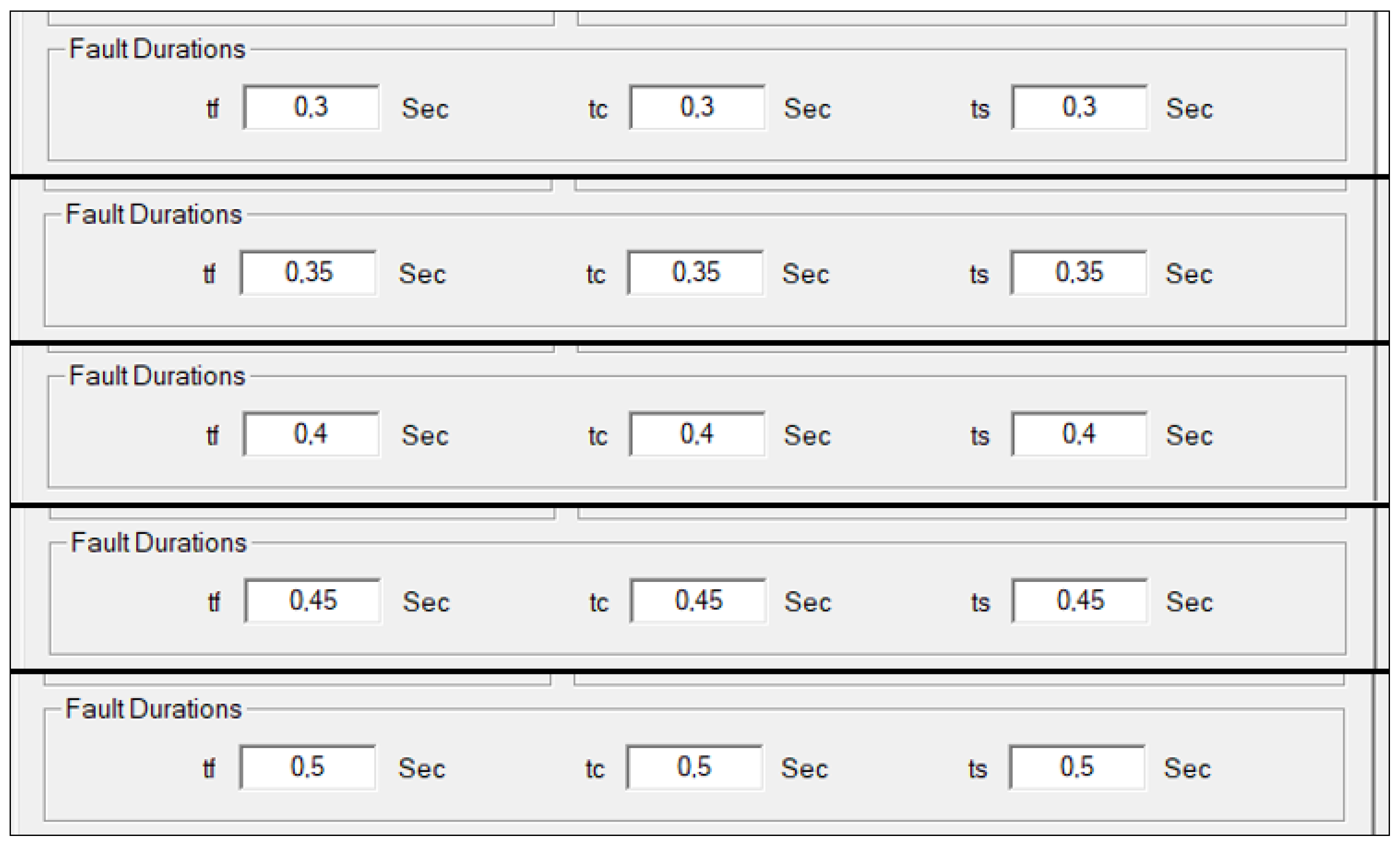
2.2.1. Fault Clearance Time Variation
Fault Clearance Time Variation—Acceptable Operating Ranges
2.2.2. Surface Material Usage
2.2.3. Diversion of the Fault Current
2.3. Earth Grid Design Considerations for Microgrids
3. Earth Grid Design Criteria
4. Refinement Methods
4.1. Current Limitation Method
4.2. Increasing the Tolerable Safety Limits of Touch and Step Voltage
4.3. Fault Current Diversion
4.4. Optimized Earth Grid Using the Refinement Methods
5. Conclusions
Author Contributions
Funding
Institutional Review Board Statement
Informed Consent Statement
Data Availability Statement
Conflicts of Interest
References
- IEEE Std 80-2013; IEEE Guide for Safety in AC Substation Grounding. The Institute of Electrical and Electronics Engineers, Inc.: New York, NY, USA, 2013.
- Prévé, C. Protection of Electrical Networks; ISTE Ltd.: London, UK, 2006; pp. 53–65. [Google Scholar]
- Cressall Resistors. A Guide to Specifying Neutral Earth Resistors (NERs); Cressall Resistors Limited: Leicester, UK, 2005; pp. 1–2. [Google Scholar]
- Scheider Electric. Industrial Electrical Network Design Guide; Schneider Electric: Rueil-Malmaison, France, 2009; pp. 160–165. [Google Scholar]
- Electrical Desk. Reactance Grounding—Operation, Advantages & Disadvantages. Available online: https://www.electricaldeck.com/2021/11/reactance-grounding-operation-advantages.html (accessed on 20 April 2023).
- Amp Control. What is a Neutral Earthing Resistor? Amp Control®: Tomago, Australia, 2017; pp. 1–3. [Google Scholar]
- IEEE Std. 32-1972; IEEE Standard Requirements, Terminology, and Test Procedure for Neutral Grounding Devices. The Institute of Electrical and Electronics Engineers, Inc.: New York, NY, USA, 1997.
- Tsvigu, O. Useful Information When Sizing a Neutral Earthing Resistor; Engineers Australia: Barton, Australian, 2020. [Google Scholar]
- Brooks, S. Fault Clearance Time. Available online: https://www.youtube.com/watch?v=phH0fFVK-AU&t=67s (accessed on 10 January 2023).
- Brewster, G. Earthing Design Fundamentals Part E: Earth Fault Clearance Times; Western Power Distribution: Bristol, UK, 2020; pp. 1–13. [Google Scholar]
- Miki, T.; Okitsu, D.; Takashima, E.; Abe, Y.; Tano, M. Power System Transient Stability Assessment Using Critical Fault Clearing Time Functions. In Proceedings of the IEEE/PES Transmission and Distribution Conference and Exhibition, Yokohama, Japan, 6–10 October 2002. [Google Scholar] [CrossRef]
- IEEE Std 242-2001; IEEE Recommended Practice for Protection and Coordination of Industrial and Commercial Power Systems (IEEE Buff Book). IEEE, Inc.: New York, NY, USA, 2001; pp. 1–710. [CrossRef]
- Biegelmeier, U.G.; Lee, W.R. New considerations on the threshold of ventricular fibrillation for AC shocks at 50–60Hz. Proc. IEEE 1980, 127, 103–110. [Google Scholar]
- Dladla, V.M.N.; Nnachi, A.F.; Tshubwana, R.P. Analysis of Design Parameters on Substation Earth Grid Safety Limits. Sci. J. Circuits Syst. Signal Process. 2022, 10, 61–72. [Google Scholar] [CrossRef]
- Garrett, D.L. Determination of Maximum Ground Fault Current through Substation Grounding System Considering Effects of Static Wires and Feeder Neutrals. In Proceedings of the Southeastern Electric Exchange, Atlanta, GA, USA, 1981; Available online: https://www.slideshare.net/SyedUbaid/substation-grounding-91726549 (accessed on 13 April 2023).
- Dawalibi, F. Ground fault current distribution between soil and neutral conductors. IEEE Trans. Power Appar. Syst. 1980, PAS-99, 452–461. [Google Scholar] [CrossRef]
- He, J.; Zeng, J.; Zhang, B. Ground Fault Current of a Substation. In Methodology and Technology for Power System Grounding; John Wiley & Sons Singapore (Pty) Ltd.: Singapore, 2013; pp. 1–7. [Google Scholar]
- Dladla, V.M.N.; Nnachi, A.F.; Tshubwana, R.P. The Impact of System Fault Level on the Design of a Substation Earthing Grid Simulation Using ETAP. In Proceedings of the 2022 30th Southern African Universities Power Engineering Conference (SAUPEC), Durban, South Africa, 25–27 January 2022; pp. 1–6. [Google Scholar]
- Sarmiento, H.G.; de la Rosa, R.; Carrillo, V.; Vilar, J. Solving electric energy supply to rural areas: The capacitive voltage divider. IEEE Trans. Power Deliv. 1990, 5, 259–265. [Google Scholar] [CrossRef]
- Lasseter, R.H. Microgrids. 2000 IEEE Power Engineering Society Winter Meeting Conference Proceedings; IEEE, Inc.: New York, NY, USA, 2002; pp. 305–308. [Google Scholar]
- IEEE Std 142-2007; IEEE Recommended Practice for Grounding of Industrial and Commercial Power Systems. IEEE, Inc.: New York, NY, USA, 2007; pp. 1–225. [CrossRef]
- de Souza, A.C.Z.; Castilla, M. Microgrids Design and Implementation; Springer: Berlin/Heidelberg, Germany, 2018. [Google Scholar]
- Kumar, D.; Zare, F.; Ghosh, A.; Microgrid, D.C. Technology: System Architectures, AC Grid Interfaces, Grounding Schemes, Power Quality, Communication Networks, Applications, and Standardizations Aspects. IEEE Access 2017, 5, 12230–12256. [Google Scholar] [CrossRef]
- Electrotechnik. SafeGridTM Earthing Article Fundamental Earthing Concepts; Electrotechnik: Sydney, Australia, 2020; pp. 1–4. [Google Scholar]


| Method | Advantages | Disadvantages |
|---|---|---|
| Solid |
|
|
| Resistive |
|
|
| Reactance |
|
|
| High-impedance |
|
|
| No. | Design Parameters Description | Value |
|---|---|---|
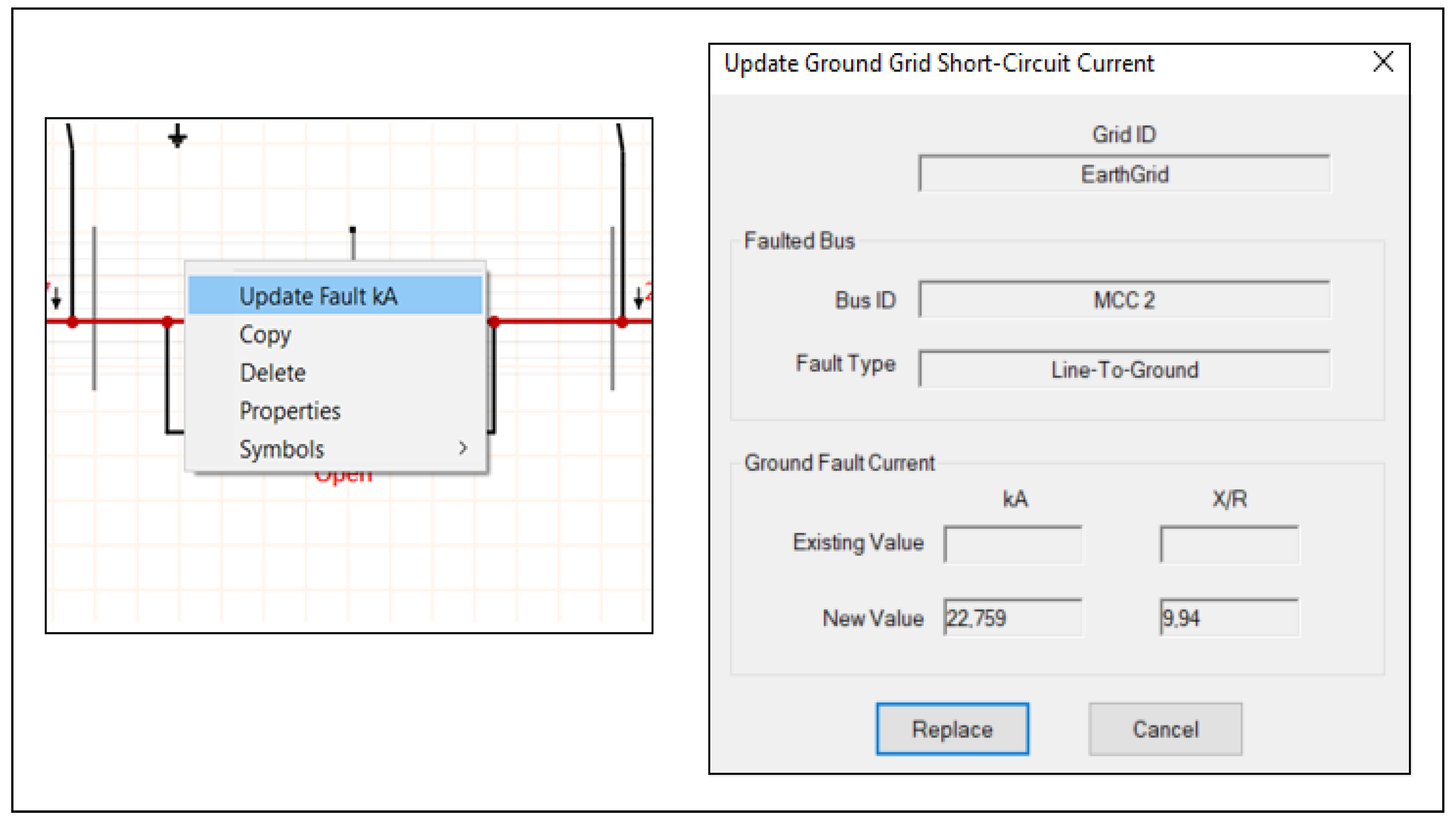
| 1 | Maximum fault current generated by the power system, 3I0 | 22.759 kA |
| 2 | Shock duration, ts | 0.4 s |
| 3 | Earth grid conductor sizing fault current duration, tc | 0.4 s |
| 4 | Decrement factor fault current duration, tf | 0.4 s |
| 5 | The resistivity of the surface layer, ρs | 4267.2 Ωm |
| 6 | The thickness of the surface layer, hs | 0.2 m |
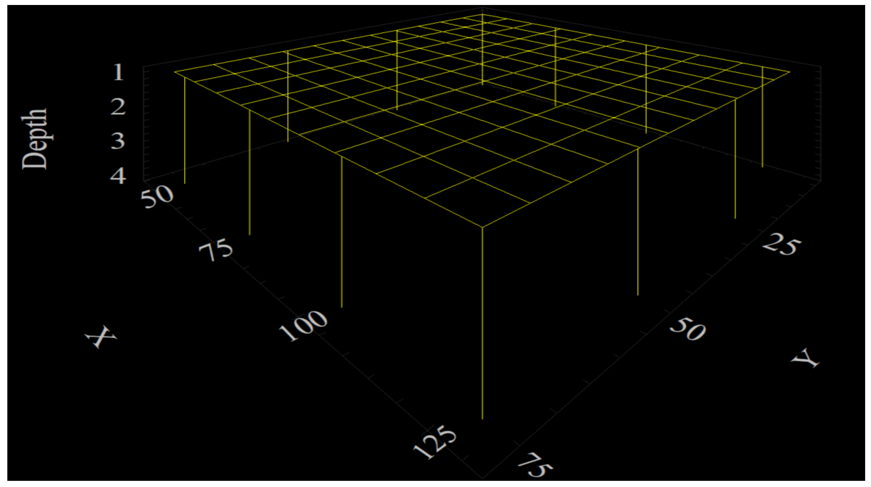
| 7 | Earth grid depth, ho | 5 m |
| 8 | Soil resistivity of the studied area, ρ | 50 Ωm |
| 9 | Depth at which the earth grid conductors are buried, h | 1 m |
| 10 | The sum of earth grid conductor lengths in the x-axis, Lx | 960 m |
| 11 | The sum of earth grid conductor lengths in the y-axis, Ly | 700 m |
| 12 | The spacing between the parallel conductor (x-axis/y-axis), D | 8.9 m/6.4 m |
| 13 | The length of each earth electrode, Lr | 3 m |
| 14 | The sum of earth electrodes, nR | 12 |
| 15 | The sum of earth grid conductors in the x-axis, Nx | 12 |
| 16 | The sum of earth grid conductors in the y-axis, Ny | 10 |
| 17 | The calculated size of the earth grid conductors | 120 m2 |
| 18 | The earth grid’s surface area (80 m × 70 m), A | 5600 m2 |
| 19 | The combined length of all buried earth grid conductors (x-axis/y-axis) (960 m + 700 m), Lc | 1660 m |
| 20 | The combined length of all earth electrodes installed (3 m × 12 m), LR | 36 m |
| 21 | The combined length of the earth grid conductors and earth electrodes, LT | 1696 m |
| Variation in Current Limitation | ||||||
|---|---|---|---|---|---|---|
| Fault Current Limit (A) | Group Potential Rise (V) | Touch Voltage (V) | Step Voltage (V) | |||
| NER Application? | Fault Current (kA) | Calculated | Tolerable | Calculated | Tolerable | |
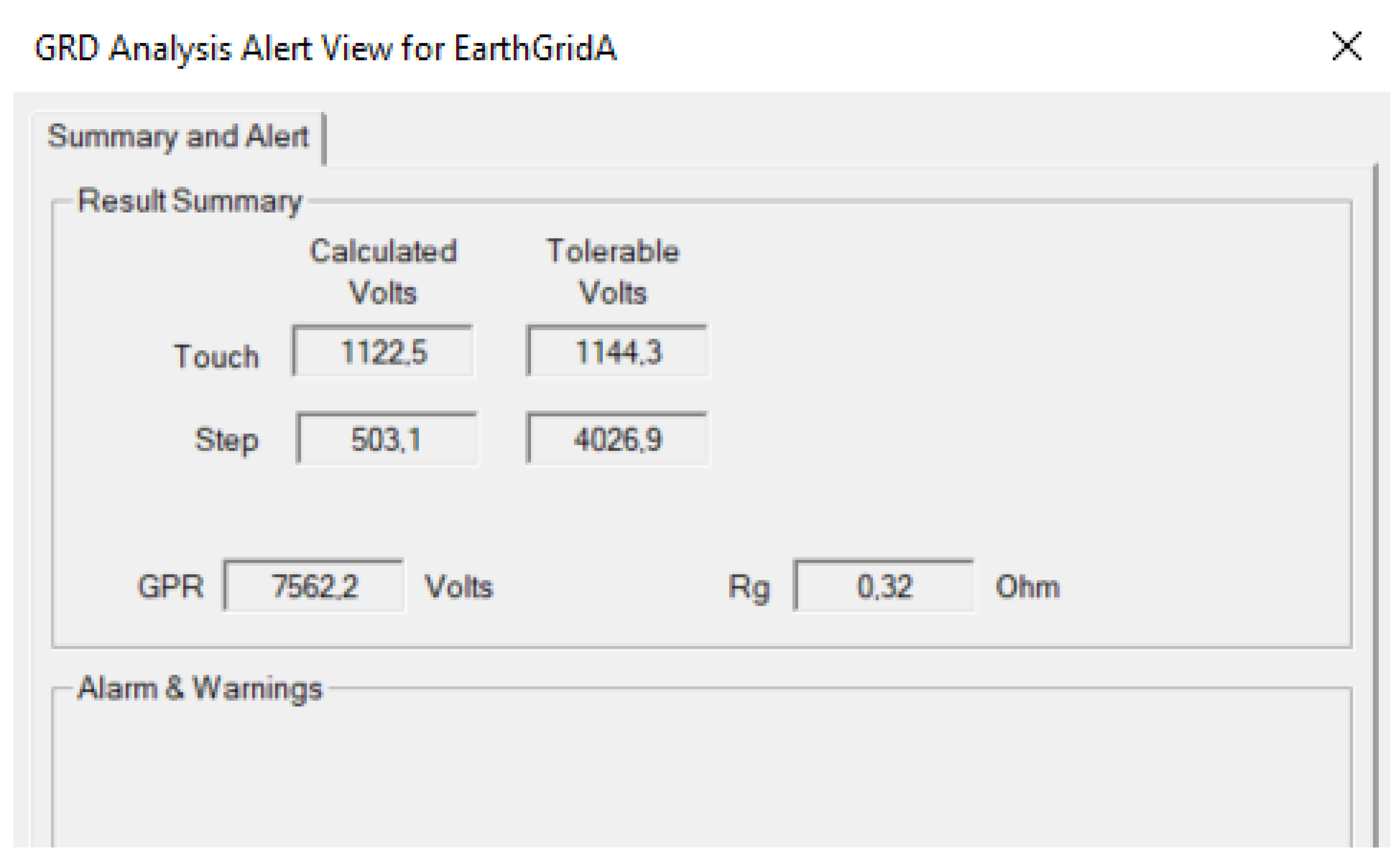
| No NER used | 22.759 | 7562.2 | 1122.5 | 1144.3 | 503.1 | 4026.9 |
| Yes—1000 A | 1.093 | 349.7 | 51.9 | 1144.3 | 23.3 | 4026.9 |
| Yes—800 A | 0.876 | 280.2 | 41.6 | 1144.3 | 18.6 | 4026.9 |
| Yes—500 A | 0.549 | 175.6 | 26.1 | 1144.3 | 11.7 | 4026.9 |
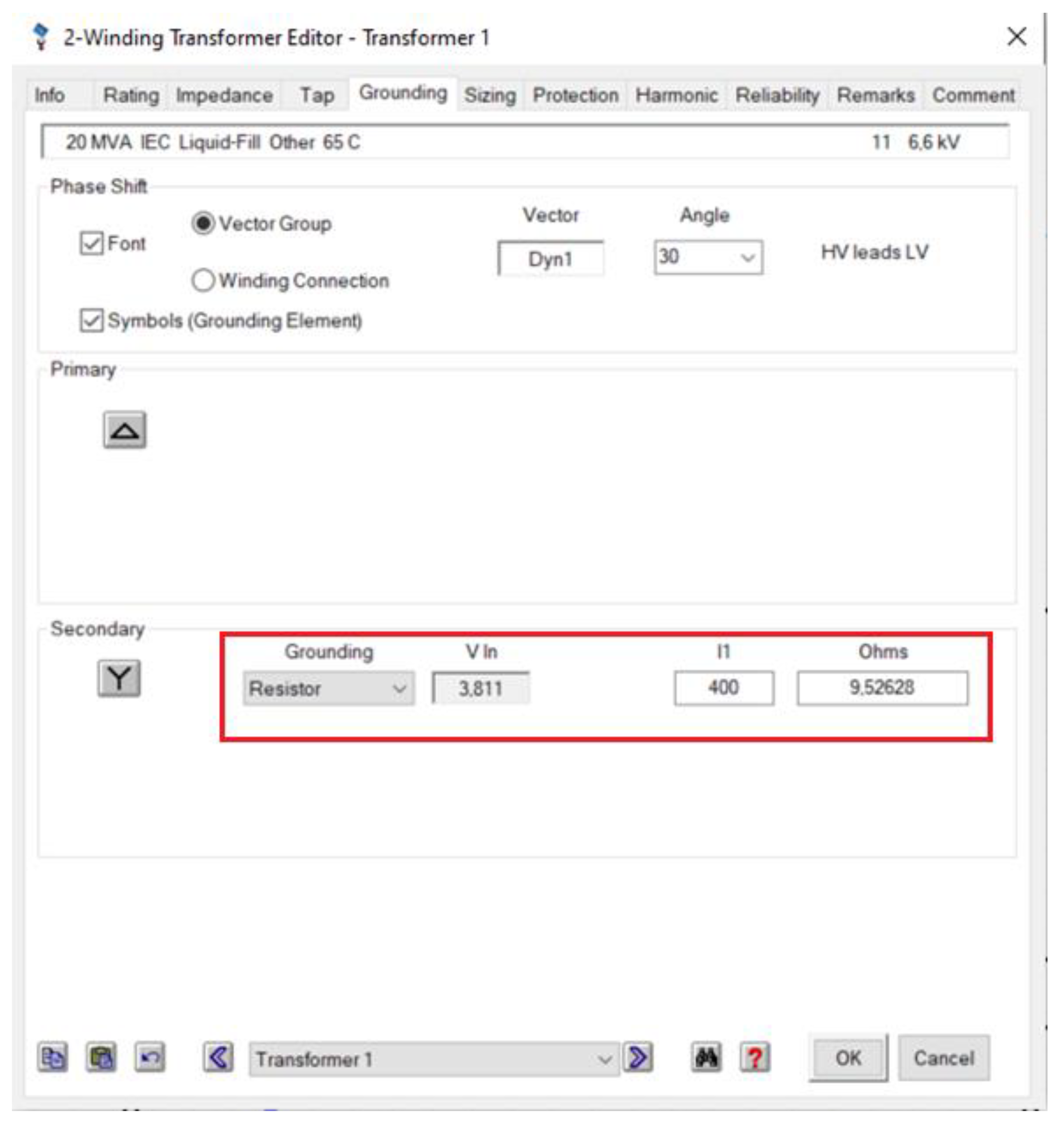
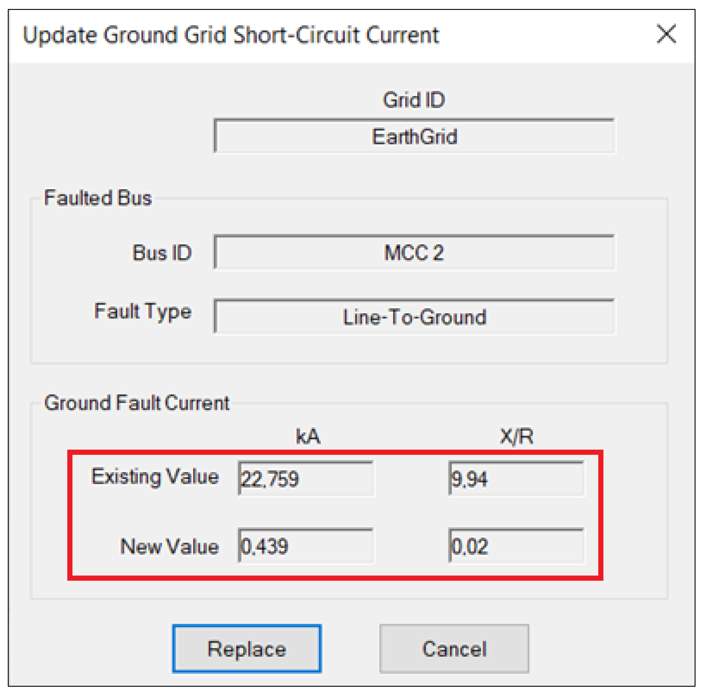
| Yes—400 A | 0.439 | 140.4 | 20.8 | 1144.3 | 9.3 | 4026.9 |
| Variation in Current Limitation | |||||
|---|---|---|---|---|---|
| Fault Duration (A) | Group Potential Rise (V) | Touch Voltage (V) | Step Voltage (V) | ||
| Calculated | Tolerable | Calculated | Tolerable | ||
| 0.3 | 7654 | 1136.2 | 1321.3 | 509.2 | 4649.9 |
| 0.35 | 7601.7 | 1128.4 | 1223.3 | 505.7 | 4305 |
| 0.4 | 7562.2 | 1122.5 | 1144.3 | 503.1 | 4026.9 |
| 0.45 | 7531.3 | 1118 | 1078.8 | 501 | 3796.6 |
| 0.5 | 7506.6 | 1114.3 | 1023.5 | 499.4 | 3601.8 |
| Variation in Current Limitation | |||||
|---|---|---|---|---|---|
| Current Division Factor (A) | Group Potential Rise (V) | Touch Voltage (V) | Step Voltage (V) | ||
| Calculated | Tolerable | Calculated | Tolerable | ||
| 100 | 7562.2 | 1122.5 | 1144.3 | 503.1 | 4026.9 |
| 90 | 6806 | 1010.3 | 1144.3 | 452.8 | 4026.9 |
| 80 | 6049.8 | 898 | 1144.3 | 402.5 | 4026.9 |
| 70 | 5293.5 | 785.8 | 1144.3 | 352.2 | 4026.9 |
| 60 | 4537.3 | 673.5 | 1144.3 | 301.8 | 4026.9 |
| Optimized Earth Grids Based on Refinement Methods | |||||
|---|---|---|---|---|---|
| Refinement Method | Group Potential Rise (V) | Touch Voltage (V) | Step Voltage (V) | ||
| Calculated | Tolerable | Calculated | Tolerable | ||
| Current Division | 4841.4 | 1131 | 1144.3 | 312.8 | 4026.9 |
| Fault Duration | 7784.1 | 1313 | 1321.3 | 518 | 4649.9 |
| Current Limitation | 153.9 | 47.9 | 1144.3 | 9.9 | 4026.9 |
Disclaimer/Publisher’s Note: The statements, opinions and data contained in all publications are solely those of the individual author(s) and contributor(s) and not of MDPI and/or the editor(s). MDPI and/or the editor(s) disclaim responsibility for any injury to people or property resulting from any ideas, methods, instructions or products referred to in the content. |
© 2023 by the authors. Licensee MDPI, Basel, Switzerland. This article is an open access article distributed under the terms and conditions of the Creative Commons Attribution (CC BY) license (https://creativecommons.org/licenses/by/4.0/).
Share and Cite
Dladla, V.M.N.; Nnachi, A.F.; Tshubwana, R.P. Design, Modeling, and Analysis of IEEE Std 80 Earth Grid Design Refinement Methods Using ETAP. Appl. Sci. 2023, 13, 7491. https://doi.org/10.3390/app13137491
Dladla VMN, Nnachi AF, Tshubwana RP. Design, Modeling, and Analysis of IEEE Std 80 Earth Grid Design Refinement Methods Using ETAP. Applied Sciences. 2023; 13(13):7491. https://doi.org/10.3390/app13137491
Chicago/Turabian StyleDladla, Vuyani Michael Nicholas, Agha Francis Nnachi, and Rembuluwani Philip Tshubwana. 2023. "Design, Modeling, and Analysis of IEEE Std 80 Earth Grid Design Refinement Methods Using ETAP" Applied Sciences 13, no. 13: 7491. https://doi.org/10.3390/app13137491
APA StyleDladla, V. M. N., Nnachi, A. F., & Tshubwana, R. P. (2023). Design, Modeling, and Analysis of IEEE Std 80 Earth Grid Design Refinement Methods Using ETAP. Applied Sciences, 13(13), 7491. https://doi.org/10.3390/app13137491