Article

Plane-Wave Diffraction from Resistive-Filled Circular Hole in Infinite Resistive Plane: An Analytically Regularizing Approach

Department of Electrical and Information Engineering, University of Cassino and Southern Lazio, 03043 Cassino, Italy
*
Author to whom correspondence should be addressed.
Appl. Sci. 2023, 13(13), 7465; https://doi.org/10.3390/app13137465
Submission received: 2 June 2023 / Revised: 22 June 2023 / Accepted: 23 June 2023 / Published: 24 June 2023

Abstract

:
The study of the electromagnetic diffraction from penetrable screens with apertures and/or inhomogeneities is of great relevance today due to the huge number of modern applications in which they are involved. In this paper, the analysis of the plane wave scattering from a resistive-filled circular hole in a resistive plane is addressed. The uniquely solvable boundary value problem for the Maxwell equations, obtained via imposing generalized boundary conditions, power boundedness condition, and Silver–Muller radiation condition, is equivalently formulated in terms of an infinite set of singular dual integral equations in the vector Hankel transform domain. The Helmholtz–Galerkin technique allows for the discretization and, simultaneously, analytical regularization of the obtained integral equations. Fast convergence is guaranteed by a suitable choice of the basis functions reconstructing the physical behavior of the fields at the discontinuity between the two involved media. Moreover, the full-wave nature of the proposed approach allows the direct assessment of near-field and far-field parameters.

1. Introduction

The classical problem of the electromagnetic field diffraction from apertures/inhomogeneities in conducting/dielectric screens has been recently receiving renewed interest due to the important role that it plays in modern applications, including high resolution near-field scanning microscopy [1], surface-plasmon assisted light beaming [2], fluorescence correlation spectroscopy [3,4], optical trapping [5], recent magnetometry strategies [6], ultra-compact spectrometers [7], extraordinary optical transmission phenomena [8,9], frequency selective surfaces [10], and so on. The difficulty in handling such structures, in which multiple diffraction and/or resonance phenomena are involved, immediately translates into the need to develop advanced analysis and synthesis techniques based on new ideas and existing analytical, semi-analytical, and numerical methods [11,12,13,14,15].
It is worth observing that a large part of the literature devoted to the diffraction from apertures is based on the perfectly conducting nature of the involved screens (see [16,17,18,19,20,21,22] for an overview). In this way, by invoking the equivalence theorem or the Babinet principle, the original problem can be replaced with an equivalent/complementary one with auxiliary unknowns defined on finite supports. Conversely, the diffraction from apertures/inhomogeneities in penetrable screens is significantly more challenging because it has to be solved directly. This explains why such a case has been rarely addressed in the past few decades [23,24,25,26]. Moreover, even using a high-performing general-purpose electromagnetic solver, one can only try to achieve accurate numerical solutions by discretizing large volumes/surfaces with an enormous cost in terms of computation time and storage requirements. On the other hand, versatility in geometry and material modeling techniques, such as the general finite-element method (FEM) [27,28] and the specialized spectral-element method (SEM) [29,30], finite-difference time-domain method (FDTD) [31,32], method of moments (MoM) [33,34], and so on, suitably adapted to the problem at hand, do not generally guarantee the convergence of the obtained approximate solutions to the exact one.
Very recently, a fast converging full-wave technique for the analysis of the diffraction from a resistive plane with a circular hole, generalizing the one introduced for studying the thin disk scattering [35,36], has been proposed [37]. Such a technique belongs to the family of the so-called methods of analytical regularization [38], which have been successfully applied by the authors to a wide class of electromagnetic problems throughout the past 20 years [39,40,41,42,43,44,45,46].
In this paper, such a technique is further generalized in order to investigate the plane-wave diffraction from a more complex structure obtained by filling the circular aperture in the resistive plane with a resistive disk of different material. In such a case, a uniquely solvable boundary value problem for the Maxwell equations is obtained by imposing the two-side generalized boundary conditions [47] on the holed plane (the external domain) and on the disk (the internal domain) together with the Silver–Muller radiation condition on the diffracted field and the power boundedness condition. By exploiting the azimuthal symmetry of the problem, it is equivalently formulated in terms of an infinite set of independent coupled dual integral equations in the vector Hankel transform (VHT) domain [48] for the VHT of the azimuthal harmonics of the effective surface current densities on the holed plane and on the disk. Suitable algebraic manipulations demonstrate that the unknowns in the internal and external domains are related to each other, thus leading to singular dual integral equations involving only unknowns defined on a finite support. It is worth observing that such a dual integral equations formulation is very general, including the ones for the resistive disk [35] and the holed resistive plane [37] as special cases. However, in the more general case at hand, the asymptotic behavior of the kernel of the integrals and the behavior of the field at the discontinuity between the two involved resistive media [49] differs from the ones of the disk and the holed resistive plane [50]. The obtained integral equations are simultaneously discretized and analytically regularized by means of the Helmholtz–Galerkin technique: (1) In order to deal with unknowns defined on finite supports with scalar spectral domain counterparts, according to the Helmholtz decomposition [51], the surface curl-free and divergence-free contributions of the azimuthal harmonics of the tangential components of the effective surface current density on the disk are assumed as new unknowns; (2) Orthogonal eigenfunctions of the most singular part of the integral operator reconstructing the field behavior around the center and at the edge of the hole are assumed to be expansion functions in a Galerkin scheme. As a result, the obtained matrix equations are fast-converging Fredholm second-kind equations in l 2 , whose elements are quickly evaluated by means of suitable analytical procedures in the complex plane [35,52]. It is worth observing that the proposed full-wave approach allows the direct assessment of near-field and far-field parameters.
The remainder of this paper is organized as follows. The formulation of the problem is presented in Section 2. The proposed solution is summarized in Section 3. Section 4 is devoted to showing that near-field and far-field can be directly evaluated. Numerical results and comparisons with the commercial software CST Microwave Studio (CST-MWS) are presented in Section 5, and the conclusions are summarized in Section 6.

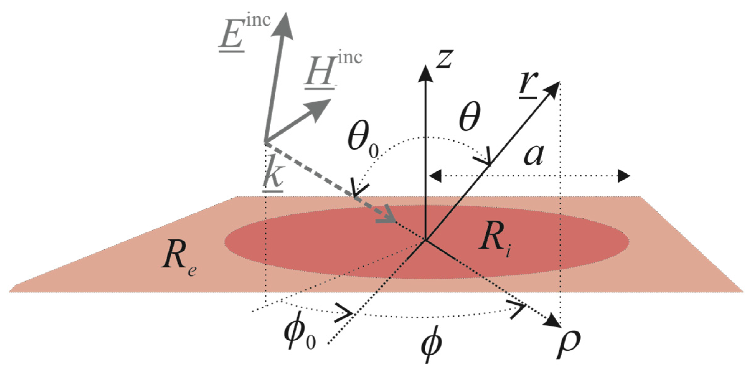
2. Formulation of the Problem

Figure 1 shows an infinite zero-thickness resistive plane of resistivity R e with a circular hole of radius a filled by a zero-thickness resistive disk of resistivity R i R e . A cylindrical coordinate system ( ρ , ϕ , z ) , with the z -axis orthogonal to the structure and the origin located at the center of the disk, and a spherical coordinate system r , θ , ϕ , such that ρ = r s θ and z = r c θ , where s t = sin t and c t = cos t , are sketched. A plane wave, propagating in the half-space z > 0 of electric field E _ i n c r _ = E _ 0 e j k _ · r _ and magnetic field H _ i n c r _ = H _ 0 e j k _ · r _ , where r _ identifies the observation point and E _ 0 and H _ 0 are constant vectors, such that H _ 0 = 1 ω μ 0 k _ × E _ 0 ; k _ = k 0 s θ 0 c ϕ 0 ϕ ρ ^ + s θ 0 s ϕ 0 ϕ ϕ ^ + c θ 0 z ^ is the wave vector; k 0 = ω ε 0 μ 0 = 2 π / λ is the free space wavenumber; ω is the angular frequency; ε 0 and μ 0 are the dielectric permittivity and the magnetic permeability of the free space; λ is the free space wavelength; and the angles θ = θ 0 and ϕ = ϕ 0 identify the incidence direction, impinges onto the structure generating a scattered field, i.e., E _ s c r _ , H _ s c r _ . Such a field in the upper/lower half-space can be interpreted as the superposition of the field reflected/transmitted by the homogeneous resistive plane, E _ r e f l / t r r _ , H _ r e f l / t r r _ , and the field diffracted due to the discontinuity in the material, E _ d i f f r r _ , H _ d i f f r r _ . Of course, the total field, E _ r _ , H _ r _ , is given by the superposition of the incidence field and the scattered field.
The following two-sided generalized boundary conditions have to be verified by the fields [47]:
z ^ × E _ ρ , ϕ , 0 + E _ ρ , ϕ , 0 = 0 _ ,
1 2 z ^ × E _ ρ , ϕ , 0 + + E _ ρ , ϕ , 0 × z ^ = R i J _ i ρ , ϕ + R e J _ e ρ , ϕ ,
for ρ 0 and 0 ϕ < 2 π , where
J _ i ρ , ϕ = z ^ × H _ ρ , ϕ , 0 + H _ ρ , ϕ , 0 ρ < a 0 _ ρ > a ,
J _ e ρ , ϕ = 0 _ ρ < a z ^ × H _ ρ , ϕ , 0 + H _ ρ , ϕ , 0 ρ > a
define the effective surface current densities on the disk and the holed plane, respectively.
Supposing R R e > 0 , conditions (1), together with the power boundedness condition and the Silver–Muller radiation condition on the diffracted field, guarantee the unique solvability of the boundary value problem for the Maxwell equations at hand [53]. Such a problem can be equivalently formulated in terms of surface integral equations for the effective surface current densities whose kernels involve the free-space dyadic Green’s function [54]. However, according to the procedure proposed in [48], for problems with azimuthal symmetry, all the field components can be expanded in Fourier series and, by invoking the VHT, the n-th azimuthal harmonic of the scattered electric field can be written in the spectral domain as follows:
E _ t s c n ρ , z = E ρ s c n ρ , z j E ϕ s c n ρ , z = 0 + H _ _ n w ρ G ~ _ _ w J ~ _ i n w + J ~ _ e n w e j k 0 2 w 2 z w d w ,
E z s c n ρ , z = j s g n z 2 ω ε 0 0 + J n w ρ J ~ i , C n w + J ~ e , C n w e j k 0 2 w 2 z w 2 d w ,
where k 0 2 w 2 = j w 2 k 0 2 .
H _ _ n w ρ = J n w ρ n J n w ρ w ρ n J n w ρ w ρ J n w ρ
is the kernel of the VHT of order n (VHTn), and J ν and J ν are, respectively, the Bessel function of the first kind and order ν and its first derivative with respect to the argument [55],
G ~ _ _ w = G ~ C w 0 0 G ~ D w = k 0 2 w 2 2 ω ε 0 0 0 ω μ 0 2 k 0 2 w 2
is related to the spectral domain counterpart of the free-space dyadic Green’s function [48], and
J ~ _ s n w = J ~ s , C n w j J ~ s , D n w = 0 + H _ _ n w ρ J _ s n ρ ρ d ρ
with s = i , e , is the VHTn of J _ s n ρ , i.e., the n-th azimuthal harmonic of J _ s ρ , ϕ .
Hence, the surface integral equations can be replaced by an infinite set of independent coupled dual integral equations in the VHT domain:
0 + H _ _ n w ρ G ~ _ _ w R i I _ _ J ~ _ i n w + G ~ _ _ w J ~ _ e n w w d w = E _ t i n c n ρ , 0   f o r   ρ < a ,
0 + H _ _ n w ρ J ~ _ i n w w d w = 0 _   f o r   ρ > a ,
0 + H _ _ n w ρ G ~ _ _ w J ~ _ i n w + G ~ _ _ w R e I _ _ J ~ _ e n w w d w = E _ t i n c n ρ , 0   f o r   ρ > a ,
0 + H _ _ n w ρ J ~ _ e n w w d w = 0 _   f o r   ρ < a ,
with n Z , where
E _ t i n c n ρ , 0 = j n + 1 e j n ϕ 0 H _ _ n k 0 s θ 0 ρ E _ 0 t
is the n-th azimuthal harmonic of the transverse component of the incident electric field.
By introducing the following auxiliary unknown:
J ~ _ e n w = G ~ _ _ w J ~ _ i n w + G ~ _ _ w R e I _ _ J ~ _ e n w + E ~ _ t i n c n w , 0 ,
where
E ~ _ t i n c n w , 0 = j n + 1 e j n ϕ 0 δ w k 0 s θ 0 w E _ 0 t
denotes the VHTn of E _ t i n c n ρ , 0 , the following alternative expressions for the equations in (7) can be readily obtained:
0 + H _ _ n w ρ G ~ _ _ w R i I _ _ G ~ _ _ w G ~ _ _ w R e I _ _ 1 G ~ _ _ w J ~ _ i n w + G ~ _ _ w G ~ _ _ w R e I _ _ 1 J ~ _ e n w w d w = E _ t t r n ρ , 0   f o r   ρ < a ,
0 + H _ _ n w ρ J ~ _ i n w w d w = 0 _   f o r   ρ > a ,
0 + H _ _ n w ρ J ~ _ e n w w d w = 0 _   f o r   ρ > a ,
0 + H _ _ n w ρ G ~ _ _ w R e I _ _ 1 J ~ _ e n w G ~ _ _ w J ~ _ i n w w d w = 1 R e E _ t t r n ρ , 0   f o r   ρ < a ,
where
E _ t t r n ρ , 0 = R e j n + 1 e j n ϕ 0 H _ _ n k 0 s θ 0 ρ G ~ _ _ k 0 s θ 0 R e I _ _ 1 E _ 0 t
is the n-th azimuthal harmonic of the transverse component of the field transmitted by the homogeneous resistive plane of resistivity R e .
By substituting (11d) in (11a), we obtain J _ e n ρ = R i J _ i n ρ for ρ < a . On the other hand, from (11b) and (11c), we immediately conclude that J _ e n ρ = J _ i n ρ = 0 _ for ρ > a . Hence,
J _ e n ρ = R i J _ i n ρ
independently of ρ , and Equation (11) is reduced to the following dual integral equations:
0 + H _ _ n w ρ G ~ _ _ w R e I _ _ 1 G ~ _ _ w R i I _ _ J ~ _ i n w w d w = 1 R e E _ t t r n ρ , 0   f o r   ρ < a ,
0 + H _ _ n w ρ J ~ _ i n w w d w = 0 _   f o r   ρ > a .
The functional space to which J _ i n ρ belongs can be readily established. Indeed, J _ i n ρ vanishes for ρ > a and is well-behaved in 0 < ρ < a , because the sources are off the scatterer surface. Moreover, the physical behavior prescribed for the fields at the discontinuity between the two involved resistive media [49] allows the conclusion that J _ i n ρ ~ ρ a O 1 , whereas, according to the Fourier series expansion properties, J _ i n ρ ~ ρ 0 ρ n 1 .
On the other hand, the following asymptotic behavior,
G ~ _ _ w R e I _ _ 1 G ~ _ _ w R i I _ _ ~ w + 1 0 0 R i / R e + O 1 / w ,
allows the establishment of the singular nature of the dual integral Equation (14).
It is easy to see that Equation (14) generalizes the ones for a resistive disk [35] and a holed resistive plane [37] that can be obtained by taking R e in the disk scenario and by using (13) and taking R i in the holed plane scenario.

3. Proposed Solution

The Helmholtz–Galerkin technique is adopted to simultaneously regularize and discretize the dual integral Equation (14).
The surface curl-free and divergence-free contributions of J _ i n ρ are assumed to be new unknowns in the spatial domain, thus leading to the scalar unknowns J ~ i , C n w and J ~ i , D n w in the spectral domain [36].
The behavior of J _ i n ρ at the disk rim and around the center of the disk can be reconstructed by expanding the unknowns in the spectral domain in the following complete and non-redundant series of weighted Bessel functions of the first kind [35,56]:
J ~ i , T n w = h = 1 + δ n , 0 + γ T , h n f ~ h n w ,
f ~ h n w = 2 n + 2 h + 2 J n + 2 h + 2 a w w ,
where T = C , D , δ n , m is the Kronecker delta function and γ T , h n are the expansion coefficients, orthonormal over the interval 0 , + with the weight function w [57], i.e.,
0 + f ~ k n w f ~ h n w w d w = 2 n + 2 k + 2 n + 2 h + 2 0 + 1 w J n + 2 k + 2 a w J n + 2 h + 2 a w d w = δ h , k
with h , k = 1 + δ n , 0 , . Moreover, the condition γ D , 1 n = j   s g n n γ C , 1 n for n 0 , where s g n · denotes the Signum function [55], has to be imposed in order to guarantee the vanishing of J _ i n ρ for ρ > a , i.e., in order to directly satisfy the equation in the external domain (14b).
The following matrix equation is obtained by applying the Galerkin method:
h = 1 + δ n , 0 + γ T , h n 0 + G ~ T w R i G ~ T w R e f ~ k n w f ~ h n w w d w = j n + 1 e j n ϕ 0 E 0 t f ~ k n k 0 s θ 0 G ~ T k 0 s θ 0 R e
with k = 1 + δ n , 0 , . Starting from (15) and (17), it is simple to show that
0 + G ~ T w R i G ~ T w R e f ~ k n w f ~ h n w w d w = 0 + G ~ T w R i G ~ T w R e κ T O 1 / w f ~ k n w f ~ h n w w d w + κ T δ h , k ,
where κ C = 1 and κ D = R i / R e . Hence, the most singular part of the integral operator is diagonalized. Moreover, following the line of reasoning in [35], it is possible to demonstrate that the remaining part of the discretized operator is a compact operator in l 2 . Since the discretized counterpart of the free term has a bounded l 2 -norm (the sources are off the scatterer surface), the obtained matrix equation is of the Fredholm second kind in l 2 , i.e., the convergence is guaranteed. On the other hand, the reconstruction of the physical behavior of the unknowns ensures the fast convergence of the method, i.e., few expansion functions lead to highly accurate results. Additionally, the matrix coefficients, which are improper integrals involving products of Bessel functions, are efficiently numerically evaluated by means of suitable analytical techniques recently developed by the authors [35,52].

4. Near-Field and Far-Field Reconstruction

Once J ~ _ i n w is reconstructed, starting from Equations (9) and (13), J ~ _ e n w can be readily obtained, i.e.,
J ~ _ e n w = G ~ _ _ w R e I _ _ 1 G ~ _ _ w R i I _ _ J ~ _ i n w + E ~ _ t i n c n w , 0 .
On the other hand, it is possible to show that the n-th harmonic of the field scattered by the homogeneous resistive plane, of resistivity R e , can be reconstructed by replacing J ~ _ i n w + J ~ _ e n w in (3) with
J ~ _ 0 n w = G ~ _ _ k 0 s θ 0 R e I _ _ 1 E ~ _ t i n c n w , 0 .
As a result, the field scattered by the source J ~ _ i n w + J ~ _ e n w J ~ _ 0 n w can be reinterpreted as the field diffracted due to the discontinuity between the involved resistive media. Hence, from (3), (10), (20), and (21), it is simple to conclude that
E _ t d i f f r n ρ , z = R i R e 0 + H _ _ n w ρ G ~ _ _ w G ~ _ _ w R e I _ _ 1 J ~ _ i n w e j k 0 2 w 2 z w d w ,
E z d i f f r n ρ , z = j s g n z 2 ω ε 0 R i R e 0 + J n w ρ G ~ C w R e 1 J ~ i , C n w e j k 0 2 w 2 z w 2 d w .
As expected, the diffracted field vanishes for R i = R e , i.e., when the inhomogeneity in the plane disappears.
Moreover, by means of the stationary phase method [53], the far diffracted electric field can be expressed in closed form as:
E s d i f f r r _ ~ r + e j k 0 r r F s θ , ϕ
for s = θ , ϕ , where
F θ θ , ϕ = ω μ 0 2 c θ R i R e G ~ C k 0 s θ R e 1 n = + e j n ϕ + π 2 J ~ i , C n k 0 s θ ,
F ϕ θ , ϕ = ω μ 0 2 R i R e G ~ D k 0 s θ R e 1 n = + e j n ϕ + π 2 J ~ i , D n k 0 s θ ,
and the bistatic radar cross-section (BRCS), defined by the diffracted field, can be readily obtained.

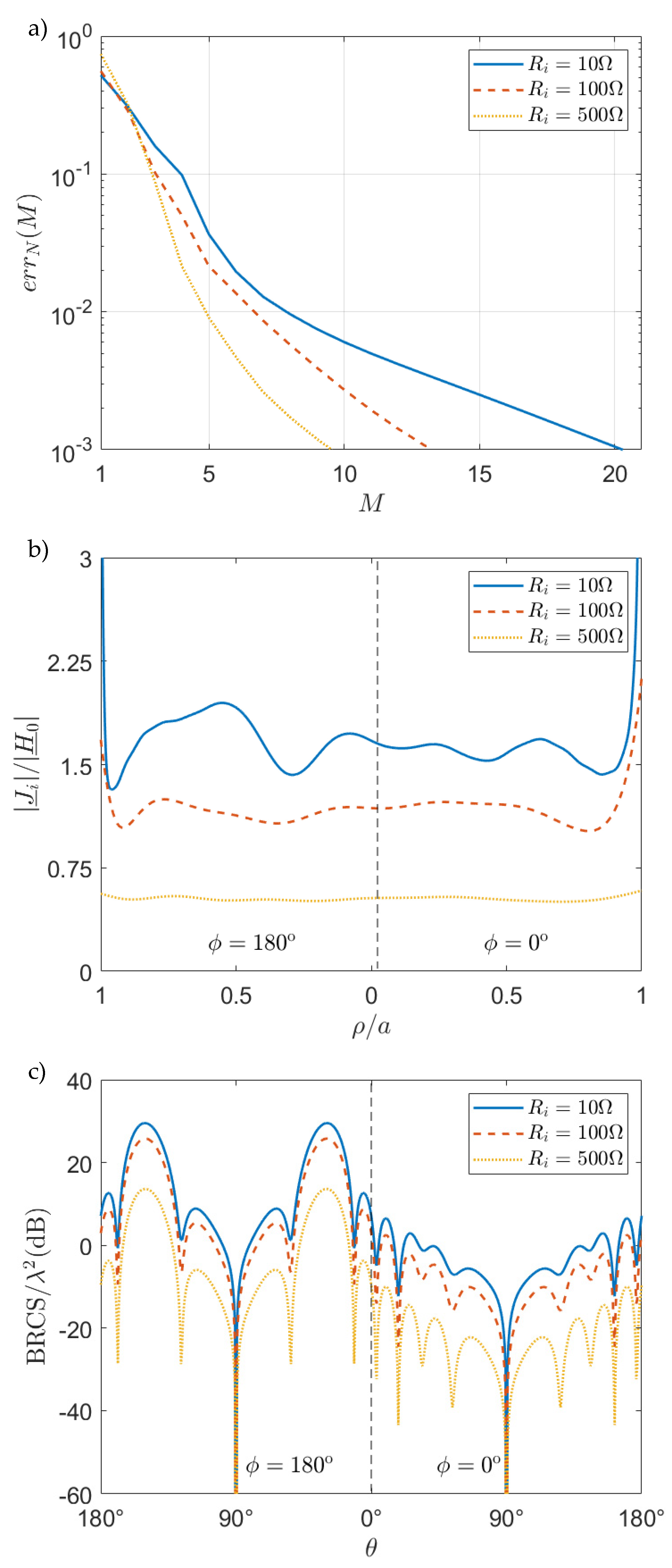
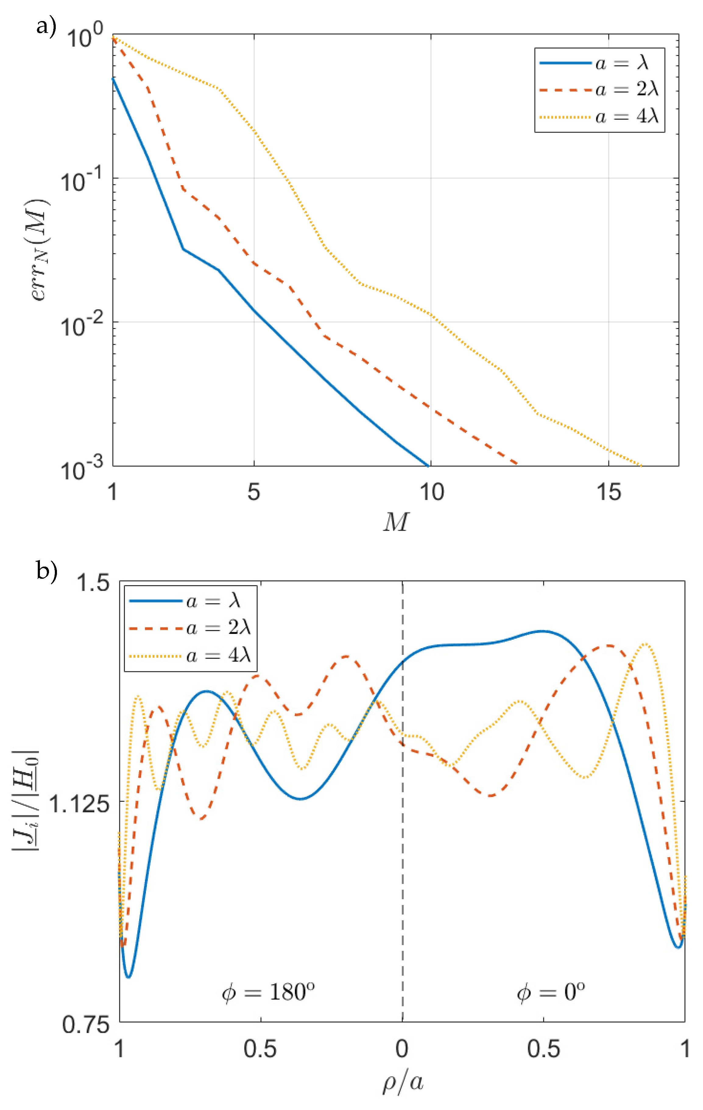
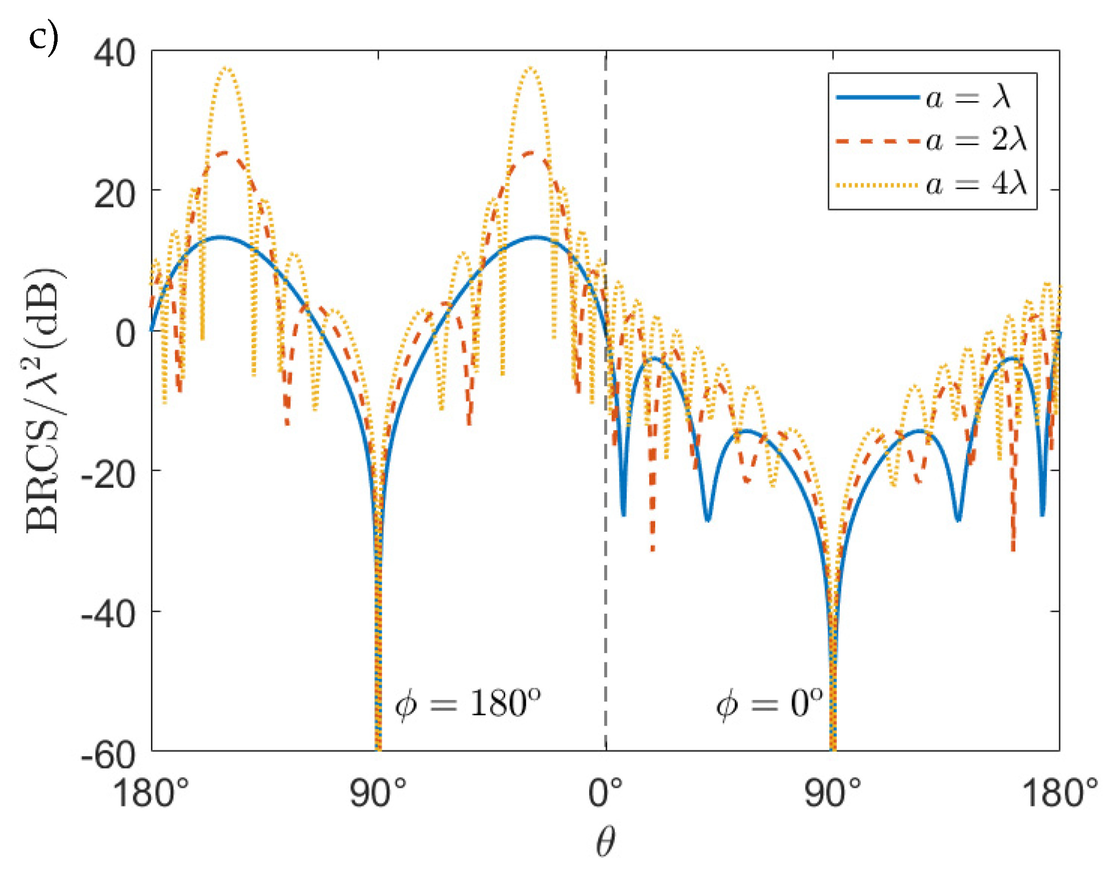
5. Numerical Results

In this section, the effectiveness of the proposed method is shown.
The convergence rate is examined by means of the following truncation error:
e r r N M = n = N + 1 N 1 x M + 1 n x M n 2 n = N + 1 N 1 x M n 2 ,
where the symbol · is used to denote the Euclidean norm, x M n is the vector of the first M expansion coefficients for each unknown, and 2 N 1 is the number of cylindrical harmonics considered. For each example, together with the behavior of the truncation error, a near-field parameter, i.e., the amplitude of the surface current density on the resistive disk, and a far-field parameter, i.e., the BRCS, are reconstructed. It is worth observing that the number of cylindrical harmonics to be used are estimated by means of the formula provided in [58], and the symmetries of the coefficient matrix allow the reduction in the number of elements to be numerically evaluated to N M 2 M + 1 . As a result, only a few seconds are needed to accurately reconstruct the solution in all the examples proposed by using an in-house software code implemented in a C++ environment on a laptop equipped with an Intel Core i7-10510U 1.8GHz, 16GB RAM.
In Figure 2, the truncation error for varying values of M , the amplitude of the surface current density on the disk along the direction θ = 90 ° and ϕ = 0 ° , 180 ° , and the BRCS in the plane ϕ = 0 ° , 180 ° are plotted for a = 2 λ , R e = 1   k Ω and different values of the resistivity of the disk, i.e., R i = 10   Ω , 100   Ω , 500   Ω , when a plane wave with TE polarization with respect to the z -axis impinges onto the structure with θ 0 = 30 ° and ϕ 0 = 0 ° . The convergence is very fast in all the cases examined in terms of numbers of cylindrical harmonics and expansion functions to be used in order to achieve a prescribed accuracy. Indeed, N = 15 is considered for all the cases and, in the worst case ( R i = 10   Ω ), the error reduced below 10 1 , 10 2 , 10 3 for M = 4 , 9 , 21 , respectively. It is interesting to observe that the convergence is faster the closer the values of the resistivities R i and R e are, i.e., the weaker the discontinuity is. Of course, even the amplitude of the diffracted field and then, the BRCS are smaller the weaker the discontinuity is. On the other hand, the decreasing amplitude of the surface current density for increasing values of R i can be explained by the higher transparency associated with higher values of R i . To conclude, as expected, the BRCS shows two maxima, in the forward direction and in the specular with respect to the incidence direction.
In Figure 3, the same parameters as in Figure 2 are plotted for R i = 100   Ω , R e = 1   k Ω , and different values of the disk radius, i.e., a = λ ,   2 λ ,   4 λ , when a TM polarized plane wave impinges onto the structure with θ 0 = 30 ° and ϕ 0 = 0 ° . Of course, the number of cylindrical harmonics and expansion functions needed to achieve a given accuracy increases by increasing the radius of the disk. Moreover, the convergence is very fast in all the cases examined. Indeed, N = 11 ,   15 ,   23 for a = λ ,   2 λ ,   4 λ , respectively. Moreover, in the worst case ( a = 4 λ ), errors smaller than 10 1 , 10 2 , 10 3 are achieved for M = 7 ,   11 ,   16 , respectively. As expected, the surface current density and the BRCS show an increasing number of oscillations for increasing values of the disk radius.
In Figure 4, in order to validate the implemented in-house software code, comparisons with CST-MWS are presented. Since CST-MWS cannot simulate the infinite holed resistive plane, it has been approximated with a zero-thickness resistive annular ring of internal radius a and external radius a ¯ . The amplitude of the surface current density on the disk along the direction θ = 90 ° and ϕ = 0 ° , 180 ° , for a = λ / 2 , R i = 100   Ω , R e = 1   k Ω , and normal incidence of the plane wave ( θ 0 = 0 ° ) with incident electric field along the direction θ = 90 ° and ϕ = 90 ° , 270 ° , is compared with the behavior obtained by using the integral equation solver of CST-MWS for two values of the external radius, a ¯ = 4 a , 8 a . As expected, the CST-MWS solution tends to the one provided by the proposed method as the external radius increases, and a quite good agreement can be observed for a ¯ = 8 a . However, the proposed method requires 9 expansion functions and 2 azimuthal harmonics (for n = ± 1 ), which results in 648 matrix coefficients, to achieve a truncation error less than 10 3 with a computation time of 2.5 s, whereas CST-MWS needs more than 5 million mesh-cells with a computation time of about 10 min to reconstruct the solution for a ¯ = 8 a . It is obvious to conclude that the proposed method drastically outperforms CST-MWS in terms of both computation time and storage requirements.
To conclude, in Figure 5, the near diffracted and total electric fields in the plane ϕ = 0 ° ,   180 ° are plotted for a = 2 λ , R i = 100   Ω , R e = 1   k Ω , and TE incidence of the plane wave with θ 0 = 30 ° and ϕ 0 = 0 ° . In this figure, the symmetric behavior of the diffracted electric field with respect to the structure with a maximum in the specular with respect to the incidence direction and the forward direction can be appreciated. Moreover, observing the total electric field behavior, it is clear that the interference between the incident and reflected waves, on one hand, and the transmitted wave, on the other hand, are perturbed by the diffraction due to the discontinuity between the two involved resistive media.

6. Conclusions

The plane wave diffraction from a resistive-filled circular hole in an infinite resistive plane has been carried out by means of an effective technique based on integral equation formulation and the Helmholtz–Galerkin technique. In this way, guaranteed convergence has been achieved according to Fredholm’s theory, and highly accurate solutions have been reconstructed with low computational resources. This last point was broadly covered in Section 5 for the general case of the oblique incidence of the plane wave and several values of the internal disk resistivity and radius. As a matter of fact, the proposed simulations, performed by means of an in-house software code implemented in a C++ environment on a laptop equipped with an Intel Core i7-10510U 1.8GHz, 16GB RAM, required just a few seconds to fill a reasonably sized coefficients matrix in order to obtain a very small truncation error in all the cases examined. Moreover, simulations with the commercial software CST-MWS were performed by approximating the infinite holed resistive plane with an annular ring and for normal incidence of the plane wave. The comparisons between the results provided by the commercial software and the ones obtained by means of the proposed method have shown that: (1) the higher the external radius of the annular ring, the better the agreement, and (2) unlike what happens with the proposed method, the commercial software requires a considerable level of computational resources to reconstruct a fairly accurate solution. To conclude, the full-wave nature of the proposed approach has led to the direct assessment of near-field and far-field parameters. This has been proven by the surface current density, the BRCS and the near-field behavior reconstructed for the cases examined. Future generalizations include the analysis of more complex structures involving dielectric materials, layered structures, and arrays of inhomogeneities.

Author Contributions

Conceptualization, M.L.; methodology, M.L.; software, M.L.; validation, G.C. and D.P.; formal analysis, M.L.; data curation, G.C. and D.P.; writing—original draft preparation, M.L., M.D.M. and F.S.; writing—review and editing, M.L., M.D.M. and F.S.; supervision, M.L. All authors have read and agreed to the published version of the manuscript.

Funding

This research received no external funding.

Institutional Review Board Statement

Not applicable.

Informed Consent Statement

Not applicable.

Data Availability Statement

The data presented in this study were obtained by means of an in-house software code implementing the proposed method.

Conflicts of Interest

The authors declare no conflict of interest.

References

  1. Betzig, E.; Trautman, J.K. Near-field optics: Microscopy, spectroscopy, and surface modification beyond the diffraction limit. Science 1992, 257, 189–195. [Google Scholar] [CrossRef] [PubMed] [Green Version]
  2. Lezec, H.J.; Degiron, A.; Devaux, E.; Linke, R.A.; Martin-Moreno, L.; Garcia-Vidal, F.J.; Ebbesen, T.W. Beaming light from a subwavelength aperture. Science 2002, 297, 820–822. [Google Scholar] [CrossRef] [PubMed]
  3. Levene, M.J.; Korlach, J.; Turner, S.W.; Foquet, M.; Craighead, H.G.; Webb, W.W. Zero-mode waveguides for single-molecule analysis at high concentrations. Science 2003, 299, 682–686. [Google Scholar] [CrossRef] [PubMed]
  4. Rigneault, H.; Capoulade, J.; Dintinger, J.; Wenger, J.; Bonod, N.; Popov, E.; Ebbesen, T.W.; Lenne, P.-F. Enhancement of single-molecule fluorescence detection in subwavelength apertures. Phys. Rev. Lett. 2005, 95, 117401. [Google Scholar] [CrossRef] [PubMed] [Green Version]
  5. Juan, M.L.; Gordon, R.; Pang, Y.; Eftekhari, F.; Quidant, R. Self-induced back-action optical trapping of dielectric nanoparticles. Nat. Phys. 2009, 5, 915–919. [Google Scholar] [CrossRef]
  6. Kihm, H.W.; Koo, S.M.; Kim, Q.H.; Bao, K.; Kihm, J.E.; Bak, W.S.; Eah, S.H.; Lienau, C.; Kim, H.; Nordlander, P.; et al. Bethe-hole polarization analyser for the magnetic vector of light. Nat. Commun. 2011, 2, 451. [Google Scholar] [CrossRef] [Green Version]
  7. Yang, T.; Xu, C.; Ho, H.-P.; Zhu, Y.-Y.; Hong, X.-H.; Wang, Q.-J.; Chen, Y.-C.; Li, X.-A.; Zhou, X.-H.; Yi, M.-D.; et al. Miniature spectrometer based on diffraction in a dispersive hole array. Opt. Lett. 2015, 40, 3217–3220. [Google Scholar] [CrossRef]
  8. Rodrigo, S.G.; de León-Pérez, F.; Martín-Moreno, L. Extraordinary optical transmission: Fundamentals and applications. Proc. IEEE 2016, 104, 2288–2306. [Google Scholar] [CrossRef] [Green Version]
  9. Sajeev, V.; Jana, A.; Mallick, S.; Devi, K.M.; Chowdhury, D.R. Coulomb interaction mediated tuning of surface plasmon resonance in terahertz hole arrays. J. Phys. Photonics 2022, 4, 045001. [Google Scholar] [CrossRef]
  10. Ali, N.M.; Ali, T.A. Simple analytical model to use in CAD tools for designing FSS devices: Plasmonic transmission through hole arrays in thin films. Appl. Phys. B 2023, 129, 15. [Google Scholar] [CrossRef]
  11. Medina, F.; Mesa, F.; Marques, R. Extraordinary transmission through arrays of electrically small holes from a circuit theory perspective. IEEE Trans. Microw. Theory Tech. 2008, 56, 3108–3120. [Google Scholar] [CrossRef]
  12. Fiala, J.; Richter, I. Interaction of light with subwavelength apertures: A comparison of approximate and rigorous approaches. Opt. Quant. Electron. 2009, 41, 409–427. [Google Scholar] [CrossRef]
  13. Gunnarsson, R.; Bäckström, M. Transmission cross section for apertures and arrays calculated using time-domain simulations. In Proceedings of the 2014 International Symposium on Electromagnetic Compatibility, Gothenburg, Sweden, 4–8 August 2014. [Google Scholar]
  14. Pinchera, D.; Migliore, M.D.; Schettino, F. Optimizing antenna arrays for spatial multiplexing: Towards 6G systems. IEEE Access 2021, 9, 53276–53291. [Google Scholar] [CrossRef]
  15. Pinchera, D.; Migliore, M.D.; Panariello, G. Isophoric inflating deflating exploration algorithm (I-IDEA) for equal-amplitude aperiodic arrays. IEEE Trans. Antennas Propag. 2022, 70, 10405–10416. [Google Scholar] [CrossRef]
  16. Bouwkamp, C.J. Diffraction theory. Rep. Prog. Phys. 1954, 17, 35–100. [Google Scholar] [CrossRef]
  17. Bowman, J.J.; Senior, T.B.A.; Uslenghi, P.L.E. Electromagnetic and Acoustic Scattering by Simple Shapes; Wiley-Interscience: New York, NY, USA, 1969. [Google Scholar]
  18. Butler, C.M.; Rahmat-Samii, Y.; Mittra, R. Electromagnetic penetration through apertures in conducting surfaces. IEEE Trans. Antennas Propag. 1978, 26, 82–93. [Google Scholar] [CrossRef]
  19. Jull, E.V. Aperture Antennas and Diffraction Theory; Peter Peregrinus: London, UK, 1981. [Google Scholar]
  20. Hongo, K.; Naqvi, Q.A. Diffraction of electromagnetic wave by disk and circular hole in a perfectly conducting plane. Prog. Electromagn. Res. 2007, 68, 113–150. [Google Scholar] [CrossRef] [Green Version]
  21. Michalski, K.A.; Mosig, J.R. On the plane wave-excited subwavelength circular aperture in a thin perfectly conducting flat screen. IEEE Trans. Antennas Propag. 2014, 62, 2121–2129. [Google Scholar] [CrossRef]
  22. Lovat, G.; Burghignoli, P.; Araneo, R.; Celozzi, S. Magnetic-field penetration through a circular aperture in a perfectly-conducting plate excited by a coaxial loop. IET Microw. Antennas Propag. 2021, 15, 1147–1158. [Google Scholar] [CrossRef]
  23. Neugebauer, H. Diffraction of electromagnetic waves caused by apertures in absorbing plane screens. IRE Trans. Antennas Propag. 1956, 4, 115–119. [Google Scholar] [CrossRef]
  24. Ashour, A.A. Electromagnetic induction in finite thin sheets. Quart. J. Mech. Appl. Math. 1965, 18, 73–86. [Google Scholar] [CrossRef]
  25. Popov, E.; Nevière, M.; Sentenac, A.; Bonod, N.; Fehrembach, A.-L.; Wenger, J.; Lenne, P.-F.; Rigneault, H. Single-scattering theory of light diffraction by a circular subwavelength aperture in a finitely conducting screen. J. Opt. Soc. Am. A 2007, 24, 339–358. [Google Scholar] [CrossRef] [PubMed]
  26. Lovat, G.; Burghignoli, P.; Araneo, R.; Celozzi, S. Axially symmetric source field penetration through a circular aperture in a thin impedance plate. IEEE Trans. Antennas Propag. 2022, 70, 8348–8359. [Google Scholar] [CrossRef]
  27. Jin, J. The Finite Element Method in Electromagnetics; Wiley: New York, NY, USA, 1993. [Google Scholar]
  28. Volakis, J.L.; Chatterjee, A.; Kempel, L.C. Finite Element Method for Electromagnetics; IEEE Press: Piscataway, NJ, USA, 1998. [Google Scholar]
  29. Lee, J.; Xiao, T.; Liu, Q.H. A 3-D spectral-element method using mixed-order curl conforming vector basis functions for electromagnetic fields. IEEE Trans. Microw. Theory Tech. 2006, 54, 437–444. [Google Scholar]
  30. Mahariq, I.; Kurt, H. On- and off-optical-resonance dynamics of dielectric microcylinders under plane wave illumination. J. Opt. Soc. Am. B 2015, 32, 1022–1030. [Google Scholar] [CrossRef]
  31. Taflove, A.; Hagness, S.C. Computational Electrodynamics: The Finite-Difference Time-Domain Method, 3rd ed.; Artech Hause: Norwood, MA, USA, 2005. [Google Scholar]
  32. Schild, S.; Chavannes, N.; Kuster, N. A robust method to accurately treat arbitrarily curved 3-D thin conductive sheets in FDTD. IEEE Trans. Antennas Propag. 2007, 55, 3587–3594. [Google Scholar] [CrossRef]
  33. Harrington, R.F. Field Computation by Moment Method; IEEE Press: New York, NY, USA, 1993. [Google Scholar]
  34. Pan, G.; Narayanan, R. Electromagnetic scattering from a dielectric sheet using the method of moments with approximate boundary condition. Electromagnetics 2004, 24, 369–384. [Google Scholar] [CrossRef]
  35. Lucido, M.; Schettino, F.; Panariello, G. Scattering from a thin resistive disk: A guaranteed fast convergence technique. IEEE Trans. Antennas Propag. 2021, 69, 387–396. [Google Scholar] [CrossRef]
  36. Lucido, M.; Balaban, M.V.; Dukhopelnykov, S.V.; Nosich, A.I. A fast-converging scheme for the electromagnetic scattering from a thin dielectric disk. Electronics 2020, 9, 1451. [Google Scholar] [CrossRef]
  37. Lucido, M. Natural mode resonances in the plane wave scattering from an infinite thin resistive plate with a circular hole. In Proceedings of the 2023 17th European Conference on Antennas and Propagation (EuCAP 2023), Florence, Italy, 26–31 March 2023. [Google Scholar]
  38. Lucido, M.; Kobayashi, K.; Medina, F.; Nosich, A.I.; Vinogradova, E.D. Guest editorial: Method of analytical regularisation for new frontiers of applied electromagnetics. IET Microw. Antennas Propag. 2021, 15, 1127–1132. [Google Scholar] [CrossRef]
  39. Lucido, M. Scattering by a tilted strip buried in a lossy half-space at oblique incidence. Prog. Electromagn. Res. M 2014, 37, 51–62. [Google Scholar] [CrossRef] [Green Version]
  40. Lucido, M.; Schettino, F.; Migliore, M.D.; Pinchera, D.; Di Murro, F.; Panariello, G. Electromagnetic scattering by a zero-thickness PEC annular ring: A new highly efficient MoM solution. J. Electromagn. Waves Appl. 2017, 31, 405–416. [Google Scholar] [CrossRef]
  41. Lucido, M.; Santomassimo, C.; Panariello, G. The method of analytical preconditioning in the analysis of the propagation in dielectric waveguides with wedges. J. Light. Technol. 2018, 36, 2925–2932. [Google Scholar] [CrossRef]
  42. Dukhopelnykov, S.V.; Lucido, M.; Sauleau, R.; Nosich, A.I. Circular dielectric rod with conformal strip of graphene as tunable terahertz antenna: Interplay of inverse electromagnetic jet, whispering gallery and plasmon effects. IEEE J. Sel. Top. Quantum Electron. 2021, 27, 4600908. [Google Scholar] [CrossRef]
  43. Herasymova, D.O.; Dukhopelnykov, S.V.; Lucido, M.; Nosich, A.I. Optical sensing of electron-beam position with twin silver nanotube antenna tuned to hybrid surface plasmon resonance. IEEE J. Sel. Top. Quantum Electron. 2021, 27, 4601008. [Google Scholar] [CrossRef]
  44. Lucido, M.; Balaban, M.V.; Nosich, A.I. Plane wave scattering from thin dielectric disk in free space: Generalized boundary conditions, regularizing Galerkin technique and whispering gallery mode resonances. IET Microw. Antennas Propag. 2021, 15, 1159–1170. [Google Scholar] [CrossRef]
  45. Lucido, M.; Balaban, M.V.; Nosich, A.I. Terahertz-range plasmon and whispering gallery mode resonances in the plane wave scattering from thin microsize dielectric disk with graphene covers. Proc. Math. Phys. Eng. Sci. 2022, 478, 2262. [Google Scholar] [CrossRef]
  46. Herasymova, D.O.; Dukhopelnykov, S.V.; Natarov, D.M.; Zinenko, T.L.; Lucido, M.; Nosich, A.I. Threshold conditions for transversal modes of tunable plasmonic nanolasers shaped as single and twin graphene-covered circular quantum wires. Nanotechnology 2022, 33, 495001. [Google Scholar] [CrossRef]
  47. Bleszynski, E.; Bleszynski, M.; Jaroszewicz, T. Surface-integral equations for electrmagnetic scattering from impenetrable and penetrable sheets. IEEE Antennas Propag. Mag. 1993, 35, 14–24. [Google Scholar] [CrossRef]
  48. Chew, W.C.; Kong, J.A. Resonance of nonaxial symmetric modes in circular microstrip disk antenna. J. Math. Phys. 1980, 21, 2590–2598. [Google Scholar] [CrossRef]
  49. Braver, I.M.; Fridberg, P.S.; Garb, K.L.; Yakover, I.M. Edge conditions for the junction of two resistive half-planes with different surface impedances. In Proceedings of the 2014 IEEE 28th Convention of Electrical and Electronics Engineers in Israel, Eilat, Israel, 3–5 December 2014. [Google Scholar]
  50. Braver, I.M.; Fridberg, P.S.; Garb, K.L.; Yakover, I.M. The behavior of the electromagnetic field near the edge of a resistive half-plane. IEEE Trans. Antennas Propag. 1988, 36, 1760–1768. [Google Scholar] [CrossRef]
  51. Van Bladel, J. A discussion of Helmholtz’ theorem on a surface. AEÜ 1993, 47, 131–136. [Google Scholar]
  52. Lucido, M.; Di Murro, F.; Panariello, G. Electromagnetic scattering from a zero-thickness PEC disk: A note on the Helmholtz-Galerkin analytically regularizing procedure. Progr. Electromagn. Res. Lett. 2017, 71, 7–13. [Google Scholar] [CrossRef]
  53. Jones, D.S. The Theory of Electromagnetism; Pergamon Press: New York, NY, USA, 1964. [Google Scholar]
  54. Colton, D.; Kress, R. Integral Equation Methods in Scattering Theory; Wiley: New York, NY, USA, 1983. [Google Scholar]
  55. Abramowitz, M.; Stegun, I.A. Handbook of Mathematical Functions; Verlag Harri Deutsch: Frankfurt, The Netherlands, 1984. [Google Scholar]
  56. Wilkins, J.E. Neumann series of Bessel functions. Trans. Am. Math. Soc. 1948, 64, 359–385. [Google Scholar] [CrossRef]
  57. Gradstein, S.; Ryzhik, I.M. Tables of Integrals, Series and Products; Academic Press: New York, NY, USA, 2000. [Google Scholar]
  58. Geng, N.; Carin, L. Wide-band electromagnetic scattering from a dielectric BOR buried in a layered lossy dispersive medium. IEEE Trans. Antennas Propag. 1999, 47, 610–619. [Google Scholar] [CrossRef]
Figure 1. Geometry of the problem.
Applsci 13 07465 g001
Figure 2. (a) Truncation error, (b) amplitude of the effective surface current density on the disk, and (c) BRCS for a = 2 λ , R e = 1   k Ω , and R i = 10   Ω , 100   Ω , 500   Ω , when a TE polarized plane wave impinges onto the structure with θ 0 = 30 ° and ϕ 0 = 0 ° . N = 15 for all the cases examined.
Applsci 13 07465 g002
Figure 3. (a) Truncation error, (b) amplitude of the effective surface current density on the disk, and (c) BRCS for R i = 100   Ω , R e = 1   k Ω , and a = λ ,   2 λ ,   4 λ , when a TM polarized plane wave impinges onto the structure with θ 0 = 30 ° and ϕ 0 = 0 ° . N = 11 ,   15 ,   23 for a = λ ,   2 λ ,   4 λ , respectively.
Applsci 13 07465 g003aApplsci 13 07465 g003b
Figure 4. Amplitude of the effective surface current density on the disk, for a = λ / 2 , R i = 100   Ω , R e = 1   k Ω , and normal incidence of the plane wave ( θ 0 = 0 ° ) with the incident electric field along the direction θ = 90 ° and ϕ = 90 ° ,   270 ° , reconstructed by means of the presented method, and using CST-MWS by approximating the holed resistive plane with a zero-thickness resistive annular ring of internal radius a and external radius a ¯ = 4 a , 8 a .
Applsci 13 07465 g004
Figure 5. (a) Near diffracted electric field and (b) near total electric field in the plane ϕ = 0 ° ,   180 ° for a = 2 λ , R i = 100   Ω , R e = 1   k Ω , and TE incidence of the plane wave with θ 0 = 30 ° and ϕ 0 = 0 ° .
Applsci 13 07465 g005
Disclaimer/Publisher’s Note: The statements, opinions and data contained in all publications are solely those of the individual author(s) and contributor(s) and not of MDPI and/or the editor(s). MDPI and/or the editor(s) disclaim responsibility for any injury to people or property resulting from any ideas, methods, instructions or products referred to in the content.

