1. Introduction
Piezomagnetic materials are functional materials that exhibit magnetic deformation when subjected to an external magnetic field. These materials find extensive applications in manufacturing non-invertible or invertible devices, including isolation devices, oscillators, filters, circulators, and modulators, as well as in fields, such as radar and satellite communication. Piezomagnetic materials used to produce high-precision intelligent components have become a rapidly developing and widely used field. However, during the processing and utilization of these materials, issues such as stress concentration due to defects (such as pores, cracks, and composite forms) can significantly reduce the expected lifespan and cause the materials to lose their original design functionality, leading to medium breakdown or failure. Therefore, the academic community has devoted considerable attention to addressing the reliability and stability issues of piezomagnetic materials [
1,
2].
The academic community is actively engaged in research to enhance the performance and reliability of piezomagnetic materials, which involves detecting and analyzing defects in these materials and the study of stress concentration and fracture mechanisms associated with these defects. Soh et al. [
3] investigated the conditions for surface harmonic waves (SH waves) at the interface between adhesive half-infinite piezoelectric and magnetic materials. They discovered that SH waves are generated and propagated at the interface of the material film within a specific frequency range, provided that the interface stiffness satisfies certain conditions. On the other hand, Singh et al. [
4] researched the propagation behavior of SH waves at the interface of adhesive infinite piezoelectric and magnetic materials. Both of these studies focused on functional gradient materials, where changes in material parameters occurred along directions parallel and perpendicular to the interface. Considering the influence of imperfect interfaces, Wei et al. [
5] investigated the diffraction problem of surface harmonic waves (SH waves) in piezoelectric/piezomagnetic plates. They demonstrated the effectiveness of the numerical solution process by solving the diffraction equation and verifying its validity through analytical derivation. Similarly, Huang et al. [
6] studied the diffraction relationship of SH waves propagating along an imperfect interface in magnetic/piezoelectric composite materials. They discovered that interface SH waves only exist at poor interfaces in specific magnetic/piezoelectric composite material combinations. These studies have significant implications for further understanding the propagation rules of SH waves in materials.
Nie et al. [
7] investigated the propagation of SH waves in a double-layer system consisting of piezoelectric and magnetic layers. They provide numerical examples to illustrate the effects of electromagnetic boundary conditions, imperfect interfaces, different piezoelectric layers, and thickness ratios on diffraction behavior. Kuo et al. [
8] performed a detailed analysis of the scattering behavior of SH waves from piezoelectric cylinders in a piezoelectric–electromagnetic matrix with imperfect interfaces. They studied two typical discontinuous interfaces to obtain the impact of scattering cross-section and field distribution. Additionally, Sun et al. [
9] studied the propagation of SH waves in ferromagnetic multiferroic composite materials composed of piezoelectric layers and magnetic central cylinders. They obtained the diffraction relationship of SH waves under two different electromagnetic boundary conditions. Liu et al. explored the propagation of SH waves in periodically layered magnetic structures and derived the diffraction equation and transmission coefficient. This study revealed the wave behavior of SH waves when the magnetic path is closed or opened, providing important implications for understanding the propagation rules and applications of SH waves in periodically structured systems. On the other hand, Qian et al. [
10] studied the propagation of SH waves in occasionally layered piezoelectric materials based on a perfect alternate structure of piezoelectric films and polymer films. They obtained the phase velocity equation, discussing the filtering effect of this structure and the impact of volume fraction and shear modulus ratio of piezoelectric layers and polymer layers on the phase velocity. This study provides important insights for designing new piezoelectric phonon crystal devices. Wang et al. [
11] studied the propagation of elastic waves in a phonon crystal containing piezoelectric and magnetic encapsulation bodies based on magnetic–electric elastic coupling while regarding the electric and magnetic fields as quasi-static. Their research has significant value for piezoelectric/piezomagnetic composite materials in microwave technology, promoting a deeper understanding of the properties of this composite material and its applications in related fields.
Electromagnetic composite materials have multiple properties that have received extensive attention in electromagnetic fields. In recent decades, many scholars have dedicated themselves to studying electromagnetic composite materials’ mechanical and electrical properties. For example, Liu et al. [
12] studied the problem of an infinite two-dimensional anisotropic piezoelectric–piezomagnetic medium containing elliptical pores. Subsequently, Pan et al. [
13] extended this method to the free vibration problem of an infinite-length anisotropic-supported piezoelectric–piezomagnetic laminate and provided numerical examples for a single-layer piezoelectric plate, a two-layer piezoelectric–piezomagnetic laminate, and a four-layer piezoelectric–piezomagnetic laminate. Pan et al. [
14] solved the problem of a three-dimensional anisotropic functional gradient piezoelectric–piezomagnetic rectangular laminate under the combined action of mechanical and electrical loads. They applied the variational principle to transform the problem of combined mechanical and electrical loads into an individual load problem. These research results provide necessary theoretical support for applying electromagnetic composite materials.
In elastic dynamics, various mathematical methods are employed to study the propagation of SH waves. Pang et al. [
15] utilized the stiffness matrix method and the transmission matrix method to investigate the transmission of SH waves through infinite/semi-infinite piezoelectric/piezoelectric and periodic composite materials. Ezzin et al. [
16] studied the propagation of SH waves through piezoelectric/piezomagnetic plates using constant differential equations and the stiffness matrix method. They discussed the impact of film thickness on the phase, group, and first-mode magnetic–mechanical coupling factor. Nobili et al. [
17] employed the coupled stress elastic indeterminacy theory to investigate the mechanical behavior of materials. They obtained the global solution for crack problems through integral transformation and the Wiener–Hopf technique. Wang et al. [
18] used complex and potential functions to study the scattering of plane harmonic waves via multiple elliptical cavities in a water-saturated soil medium. Yu et al. [
19] proposed a double orthogonal polynomial series method, which can be used to design and optimize multi-layer piezoelectric voltage–magnetic material transducers.
Lamb waves and surface waves hold great importance in research as unique waves. Cao et al. [
20] studied the propagation of Lamb waves in a functional gradient piezoelectric–piezomagnetic material plate, considering the continuous change in material parameters along the thickness direction. They solved the constant differential equation with variable coefficients using the power series method and considered the continuous variation in material parameters along the thickness direction. Pang et al. [
21] calculated the dispersion curves and displacement fields of Lamb waves in layer-periodic composite materials composed of piezoelectric–piezomagnetic materials for different volume fractions of piezoelectric materials. Li et al. [
22] used the Bond transformation to study the impact of piezoelectric and magnetic effects on the surface wave velocity of magnetic elastic solids. They derived the long-term equation satisfied by the surface wave velocity. Zakharovenko et al. [
23] studied the characteristics of shear-horizontal surface acoustic waves in Alfenol, Terfenol-D, Metglas, and NiFe
2O
4 piezoelectric cubic single crystals. These research results provide theoretical guidance for analyzing and designing magnetic and electric transducers in functional gradient materials and provide academic advice for ultrasound non-destructive evaluation. Additionally, piezoelectric–piezomagnetic materials have extensive applications in biomedical engineering, such as ultrasound imaging and treatment.
In summary, scholars have extensively researched the elastic dynamics and structural dynamics of piezoelectric materials and their composite materials. However, research on the structural dynamic behavior of non-circular open magnetic materials is relatively rare. Given the widespread application of piezoelectric and magnetic materials, studying the dynamic stress concentration is of great value.
2. Governing Equations
For a steady-state elastic field and electric field under the action of a periodic load, the field variables can be expressed in the following separated form with time-harmonic factors and spatial variables
where
is a complex function and its real part is the solution of the problem. The spatial function
L is the main subject of study.
Considering the case of SH wave incident on the
xy-plane, assuming that the
z-axis is the polarization direction, the control equations of the steady-state anti-plane dynamic problem are
where the components
and
are the anti-plane shear stress components;
and
are the magnetic displacement components.
w,
ρ, and ω, respectively, represent the displacement on the
z-axis, the density, and the circular frequency of the steady-state waves.
Thus, the constitutive relation of piezomagnetic materials can be expressed as
where the
c44,
h15, and
μ11 represent the elastic constants, piezomagnetic stress constants, and magnetic constants, respectively.
ϕ represents the magnetic potential within the medium.
Substituting Equation (3) into Equation (2), we can obtain the following form
where the
represents the wave number and
represents the modulus of magnetic hardening elastic constant.
The magnetic potential can be determined by
In a cylindrical coordinate system, Equation (4) can be written in the following form
Meanwhile, Equation (3) can be transformed into the following form
The method of complex function and conformal mapping can be employed to solve the boundary value problem of non-circular openings, as shown in
Figure 1. After introducing complex variables
and
and using conformal mapping, Equation (4) can be expressed as
On the mapping plane (
η,
θ), we can utilize the following equation
Equation (7) can be transformed as
In the original plane, the angle between the SH wave vector and the positive
x-axis vector is denoted as
φ. In the mapping plane, we can express the elastic field and magnetic potential as follows
where the
is the amplitude of the incident wave. The above equation omits the time factor
.
By employing the wave function expansion method, we can express Equation (11) as follows
Simultaneously, the scattered wave generated by an irregular opening can be expressed as
where the
represents the first-type Hankle function, and
,
,
, and
are undetermined constants.
For piezomagnetic materials, we can express the total elastic field and total magnetic potential as follows
Consider condition
,
,
can be obtained.
We can express the magnetic potential of the opening with no elastic field but a magnetic field
as follows
where
,
, and
are undetermined constants.
3. Boundary Conditions and Modal Coefficients
On the mapping plane, we can represent the boundary conditions as follows
By utilizing Equation (5) and substituting the third equation of Equation (10) into the second equation of Equation (16), we can obtain
where
μ0 is the vacuum permeability.
By utilizing the second formula of Equations (14) and (15), we can express Equation (17) as follows
Assuming that the mapping plane of the opening is the unit circle, we can express Equations
and
, as well as Equation (18), as follows
As
and
are both non-zero and independent of each other, we can conclude that
By substituting the third equation of Equations (14), (15), and (20) into the third equation of Equation (16), we obtain
Substituting the first equation of Equation (10) into the first equation of Equation (16), we obtain
We can obtain the following relation
By utilizing Equation (23), Equation (22) can be expressed as follows
where
is a dimensionless parameter that characterizes the fundamental properties of piezomagnetic materials.
By multiplying both sides of Equations (21) and (24) by
(m
Z) and integrating over interval (0, 2π), we can obtain an infinite system of algebraic equations in the following form
where the elements
,
,
,
, and
in the equation are listed in
Appendix A.
As cylindrical functions exhibit convergence, we can set n as the maximum value of N in Equation (25), i.e., n = N. This results in 2N + 1 undetermined coefficients for , N undetermined coefficients for and , and one undetermined coefficient for , making a total of 4N + 2 undetermined coefficients. With two infinite algebraic equations, we can construct 4N + 2 equations, providing sufficient conditions to solve these undetermined coefficients. To solve the equation , where X is a (4N + 2) × 1 order matrix of undetermined coefficients, we employ linear algebra theory. Ω is a square matrix of order (4N + 2) × (4N + 4), constructed by , , , , , , , and , serving as the coefficient matrix. Meanwhile, Ψ is a non-homogeneous coefficient matrix, which is a (4N + 2) × 1 matrix constructed by and . We then use to obtain the solution for the undetermined coefficients.
5. Numerical Calculation and Discussion
Upon analyzing the above expressions, we observe that physical Equation (26) is a convergent infinite series function. When
n = 10, the calculated results meet the required engineering accuracy. For our analysis, we selected CoFe
2O
4 as the material of interest, with a relative material constant of [
24]
For our numerical analysis, we consider the incident wave number ka, the incidence angle φ of the SH wave, and the elliptical geometric parameters e = b/a as the characteristic parameters.
Figure 2 illustrates the distribution of the DSCC during the incidence of SH waves along the major axis (
φ = 0) and minor axis (
φ = π/2) of an elliptical opening with varying geometric parameters (
e = 0.3, 0.5, 0.7, 0.9). The symmetric shape of the elliptical opening in the incident direction results in a symmetric distribution of DSCC regions. Moreover, increasing the wave number leads to a decrease in the DSCC, particularly in the shadow region, where the decline is more pronounced. When waves are incident along the major axis of the elliptical opening, the DSCC attains its maximum value as the e value increases. However, the situation is reversed when waves are incident along the minor axis of the elliptical opening. Notably, waves incident from the minor axis exhibit a larger DSCC than those from the major axis.
Figure 3 displays the distribution of the DSCC around the elliptical opening for various wave numbers of SH waves. When e is small, the non-symmetric incidence of SH waves significantly affects the shape of DSCC, as depicted in
Figure 3a. As
e approaches 1, DSCC becomes symmetrically distributed around the incident direction, and the maximum value decreases. Furthermore, an increase in the incident angle results in an increase in DSCC at low wave numbers.
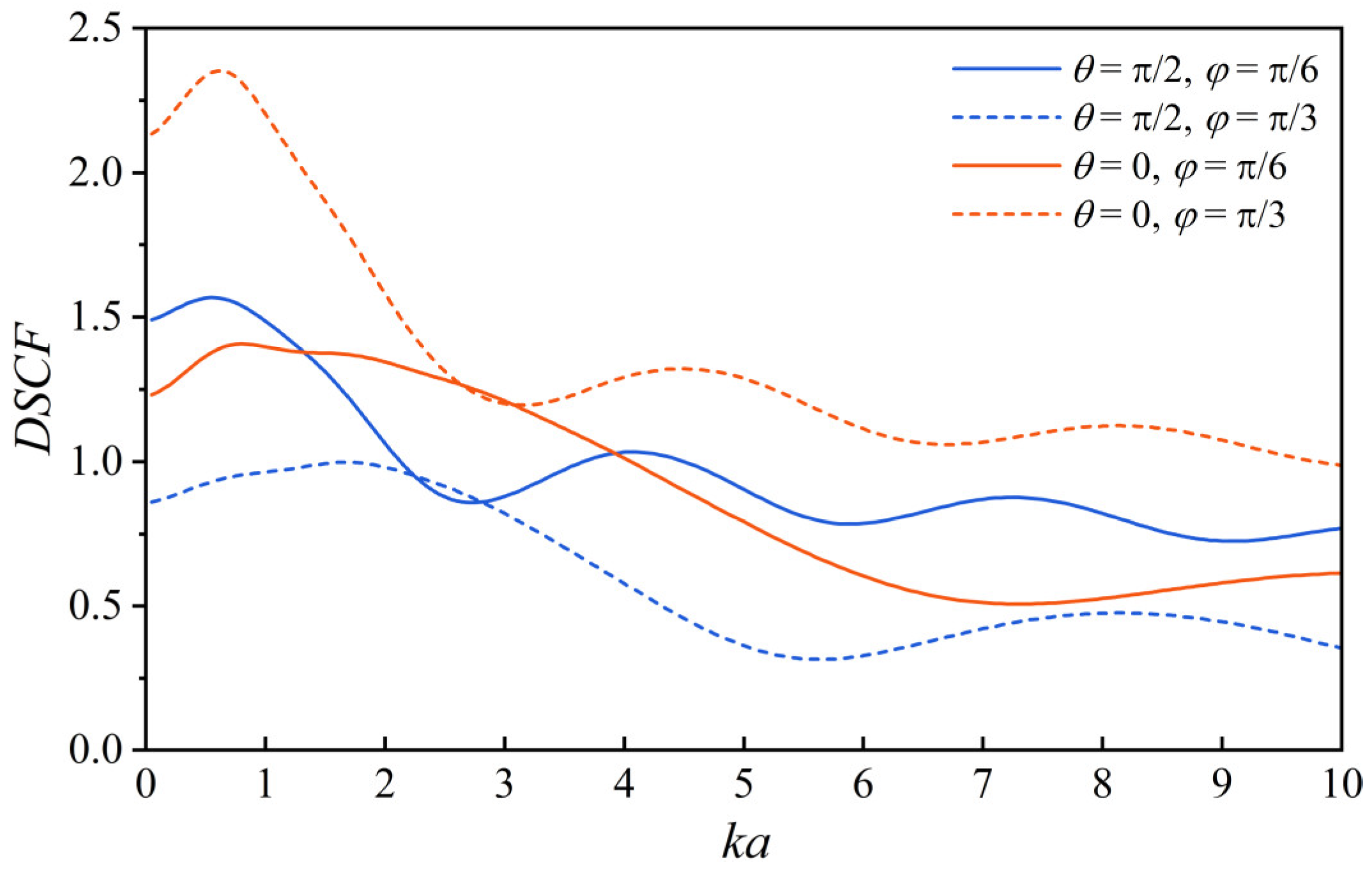
Figure 4 displays the correlation between the DSCC and the dimensionless wave number. The solid line represents the incidence angle
φ = π/6, while the dashed line represents the incidence angle
φ = π/3. At the elliptical position
θ = π/2, the DSCC decreases with an increase in the incidence angle, whereas the opposite trend is observed at
θ = 0. The DSCC attenuates with fluctuations in the wave number at both incidence angles. Notably, a lower wave number results in a larger DSCC.
Figure 5 depicts the correlation between the DSCC and the incident angle. The solid line represents a low wave number
ka = 0.5, while the dotted line represents a high wave number
ka = 3.0. The trend reveals that the DSCC at elliptical positions
θ = 0 and
θ = π/2 changes in opposite directions. In the low-wave-number case, the DSCC curve is monotonically increasing. The DSCC curve is lower than the low-wave-number case for high wave numbers and exhibits fluctuations. Notably, the DSCC change at elliptical position
θ = 0 is steeper than at elliptical position
θ = π/2.


 ,
, 


