1. Introduction
Compared with traditional fixed-wing UAVs [
1], quadrotor UAVs have become more popular in recent years. Because quadrotor UAVs have the advantages of low cost, a small size, and strong anti-interference, they are used in the fields of detection and survey [
2], disaster rescue [
3], traffic monitoring [
4], the military [
5], and news reporting [
6]. They can take the place of people to perform difficult and dangerous tasks, and are gradually showing great application potential in the civil and military fields [
7].
The quadrotor is a complex system with multiple degrees of freedom, strong coupling, and an underdrive that requires high control accuracy as it is susceptible to gusts of wind, air friction, and perturbations within the UAV [
8] when performing missions. Problems such as yawing and loss of control can occur, affecting the progress of the mission and the safety of people. Furthermore, the application of quadrotors in various fields is becoming more finely segmented, which causes problems such as shorter flight times. Thus, how to control the smooth flight of quadrotor UAVs and achieve a longer range with the original accessories [
9] has become a hot topic of discussion nowadays.
In order to adapt to the specific needs of quadrotor UAV control performance, many intelligent control schemes have been proposed for quadrotor UAVs at home and abroad, such as fuzzy PID control [
10], neural networks [
11], adaptive control [
12], LQR [
13], ADRC [
14], SMC [
15], etc. PID control algorithms are widely used in industrial production because of their simplicity, few adjustable parameters, and low dependence on accurate models. Reference [
16] proposed a controller parameter that uses a multi-objective particle swarm optimization (PSO) algorithm to improve PID performance and adjusts the PID online to solve the problems of system instability, slow response, and error tracking due to parameter deviations. In reference [
17], a novel adaptive neural network-based controller was proposed that does not require knowledge of the system parameters and achieves online updating of the output weight matrix, which can effectively eliminate the bias caused by the parameter uncertainty of the inner loop. Reference [
18] proposed an adaptive fuzzy tracking control scheme, which applies a nonlinear disturbance observer to compensate for the external disturbances and the approximation error of the fuzzy logic system, and in most cases, adaptive control is mostly applied to identify the quadrotor dynamics and external disturbances online or to design robust controllers in combination with other control techniques [
19]. The LQR controller [
20] is able to track the desired position and attitude trajectory and the spiral trajectory well, and this strategy is able to compensate for the effect of the load on the control system dynamics. LADRC [
21] has a good tracking capability and anti-interference capability, and can treat external disturbances as well as internal uncertainties as a total disturbance by LESO and compensate for them with a PD controller, but it has too many adjustment parameters and a limited ability to handle external disturbances. Reference [
22] proposed a modified terminal-sliding mode controller, which is a strategy with a time-varying delayed output observer that allows the quadrotor UAV to operate smoothly for a limited period of time. In references [
23,
24], an improved LADRC controller was proposed to improve the dynamic capability of the distribution network under various grid defect scenarios. In summary, conventional control methods are subject to internal uncertainties, unmodeled parts, and external nonlinear disturbances that can lead to poor control performance and make it difficult to design controllers due to the complexity of the quadrotor itself. In addition to their own shortcomings, the control methods described above cannot simultaneously take into account internal parameter uncertainties by coupling between quadrotor control channels, wind disturbances, and other nonlinear disturbances, and can only deal with one or two disturbances; thus, further research is needed.
If the quadrotor is disturbed, the goal is for it to continue to fly on the optimal path [
25] to reach the desired position using the shortest path and to obtain a longer endurance based on the original energy. Combining the advantages of the above control schemes, this paper utilizes LADRC and SMC to design a simple and more robust quadrotor cascade control scheme for quadrotor UAVs with long endurance. The contributions of this paper are outlined as follows:
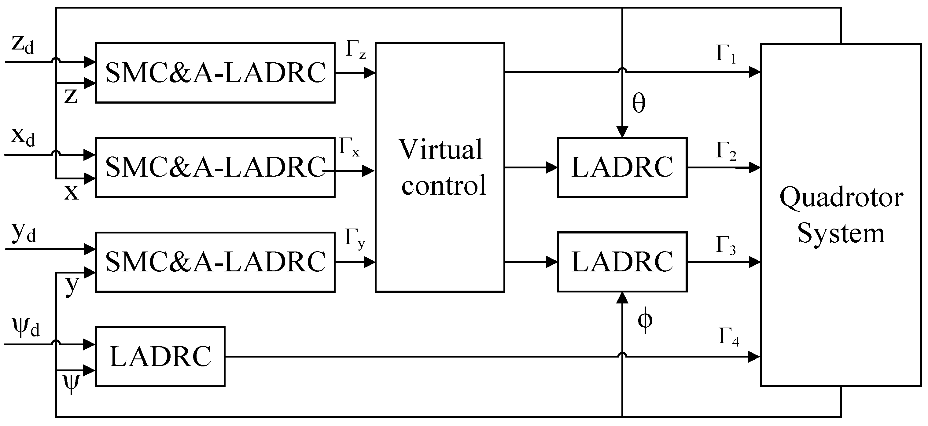
First, when the quadrotor UAV is in flight, external disturbances, internal disturbances, and controller parameter deviations can all affect its smooth operation. LADRC can effectively estimate the internal and external disturbances of the system, but there are many adjustable parameters; therefore, we introduce adaptive control to adjust the PD controller parameters online according to the input and output of the system. This adaptive LADRC-based quadrotor UAV control system can effectively compensate for the tracking error caused by the controller parameters and make the control system more robust.
Secondly, this paper proposes a cascade control system design based on linear active disturbance rejection control with sliding film control as the outer loop of the control system and adaptive control-based LADRC as the inner loop of the control system. This strategy, by introducing SMC, can effectively improve the robustness of the controller and accelerate the response speed. The position control channels of the quadrotor system are controlled by independent SMC&A-LADRC. This strategy can effectively suppress the external interference of the quadrotor, overcome the shortcomings of low LADRC tracking accuracy, and realize the quadrotor UAV flying with the optimal path to achieve long endurance flight.
Third, LESO can estimate and compensate for the total disturbance of the quadrotor system in real time. We treat the chattering caused by SMC as disturbance, observe it in real time by LSEO, and then compensate for it by PD controller to further improve the robustness of SMC&A-LADRC. The control scheme combines the advantages of both, uses LESO to solve the problem of chattering in SMC, and applies it to the position control channel, so that the quadrotor still follows the desired trajectory when disturbed, and achieves the purpose of an optimal flight path.
The structural framework of this paper is presented as follows:
Section 2 presents a six-degrees-of-freedom quadrotor UAV dynamics model.
Section 3 proposes a LADRC-based tandem control scheme for the quadrotor system and proves the stability of the system by Lyapunov theorem of stability.
Section 4 simulates and analyzes the control strategy proposed in this paper and tests the trajectory tracking of the quadrotor UAV under different conditions. Finally,
Section 5 provides a detailed summary of this paper.
2. Mathematical Models
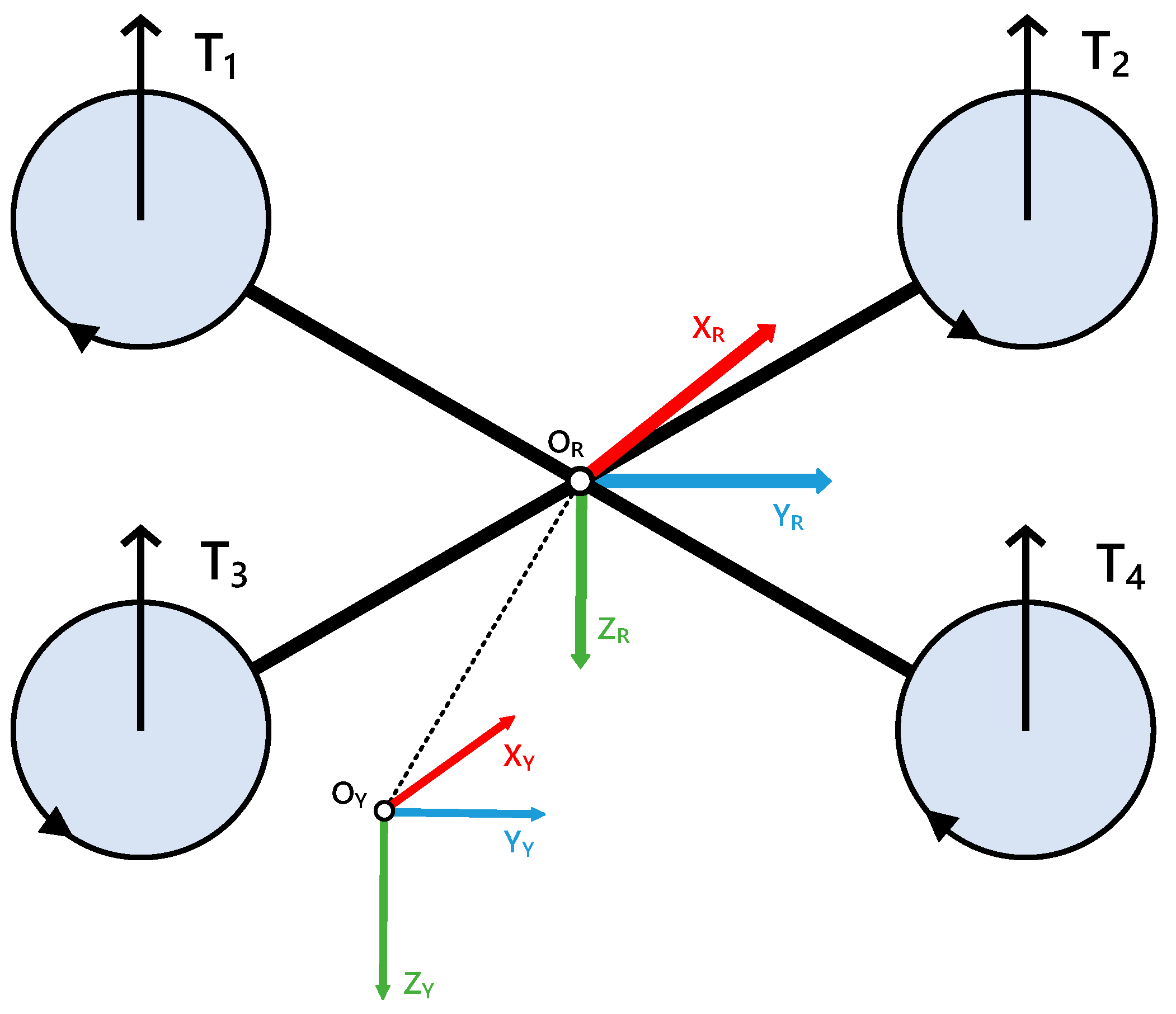
The quadrotor UAV is a system with six-degrees-of-freedom driven by four motors, and its translational and rotational motions are achieved through motor speed regulation.
,
and
are used to control the position channel of the quadrotor;
,
and
are used to control the attitude channel of the quadrotor. In order to obtain an accurate quadrotor dynamics model [
26], the internal friction of the airframe is neglected, the quadrotor is considered as a rigid structure, the earth coordinate system
and the airframe coordinate system
are established, and the structure diagram and reference coordinate system of the quadrotor are shown in
Figure 1.
The transformation relationship of the quadrotor from the Earth coordinate system
to the airframe coordinate system
is expressed in terms of the attitude matrix
[
27] as:
We introduce
,
,
and
to denote the lift generated by the four motors; therefore, the flight dynamics of the quadrotor can be expressed as:
In the fuselage coordinate system
, bringing in the rotation matrix and associating Equations (1) and (3), the lift of the quadrotor can be expressed as:
In the Earth coordinate system
, the mathematical model of the position channel is expressed as:
where
indicates the torque coefficient;
represents the mass of the quadrotor;
represents the acceleration of gravity.
Further, the channels for attitude control can be expressed as:
where
,
, and
express the rotational inertia of the
,
and
-axis, respectively;
is the coefficient of air resistance;
is the distance between aircraft center and rotor center.
For the convenience of the study, we introduce the dummy variable to replace and the dummy variable , , to simplify the mathematical model of the quadrotor position motion.
where
, the intermediate variables of the simplified model are expressed as:
From Equations (4)–(7), the mathematical model of the quadrotor is obtained as:
where
4. Simulation
The simulation analysis of quadrotor for multiple trajectory tracking is performed using MATLAB/Simulink. Assume that the initial position is , the initial posture is .
The parameters of the quadcopter system are shown in
Table 1, the parameters of the LADRC control system are shown in
Table 2, and the parameters of the SMC&A-LADRC control system are shown in
Table 3. In order to reduce the parameters that can be adjusted by LADRC, we have given the parameter values of
by an empirical trial-and-error method.
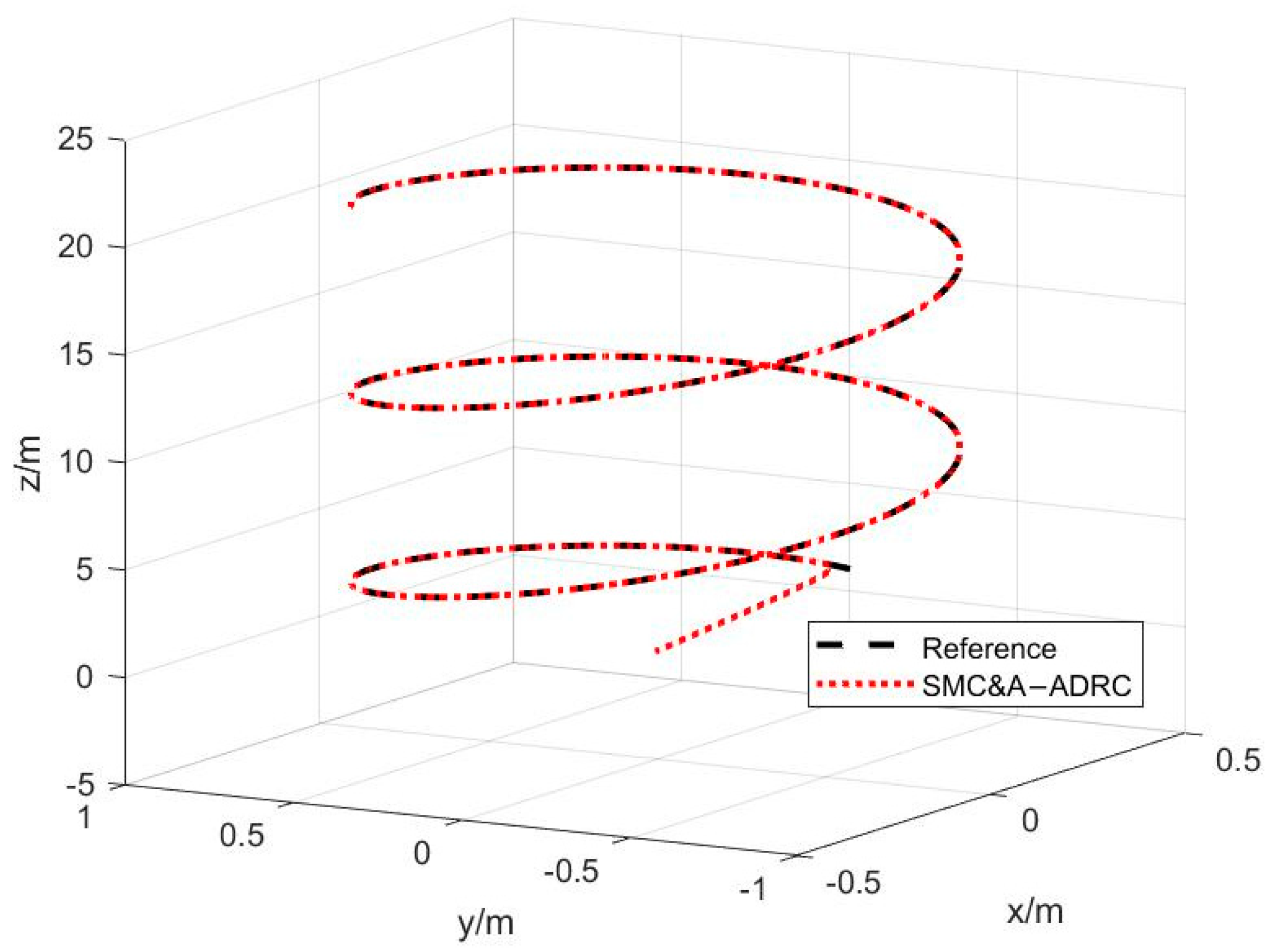
Simulation Example 1. This is a trajectory tracking simulation designed to test the trajectory tracking performance of SMC&A-LADRC, the desired trajectory is a spiraling circle and the desired signal input is shown in Equation (37): The results of trajectory tracking are shown in
Figure 4, and the curves of position and attitude channels are shown in
Figure 5 and
Figure 6, respectively.
The purpose of simulation case 1 is to test whether the control system proposed in this paper is effective. The trajectory tracking curve of a quadrotor in 3D coordinate system is given in
Figure 4. It is clear from the figure that the SMC&A-LADRC control scheme proposed in this paper can respond quickly and track the desired signal accurately and steadily. The tracking curves of position channel
,
and
are given in
Figure 5a–c, respectively. In-depth analysis can be obtained that all three position channels achieve stable tracking at 0.8 s with error control of 0.001% and no significant overshoot. The tracking curves of the attitude channel
,
and
are given in
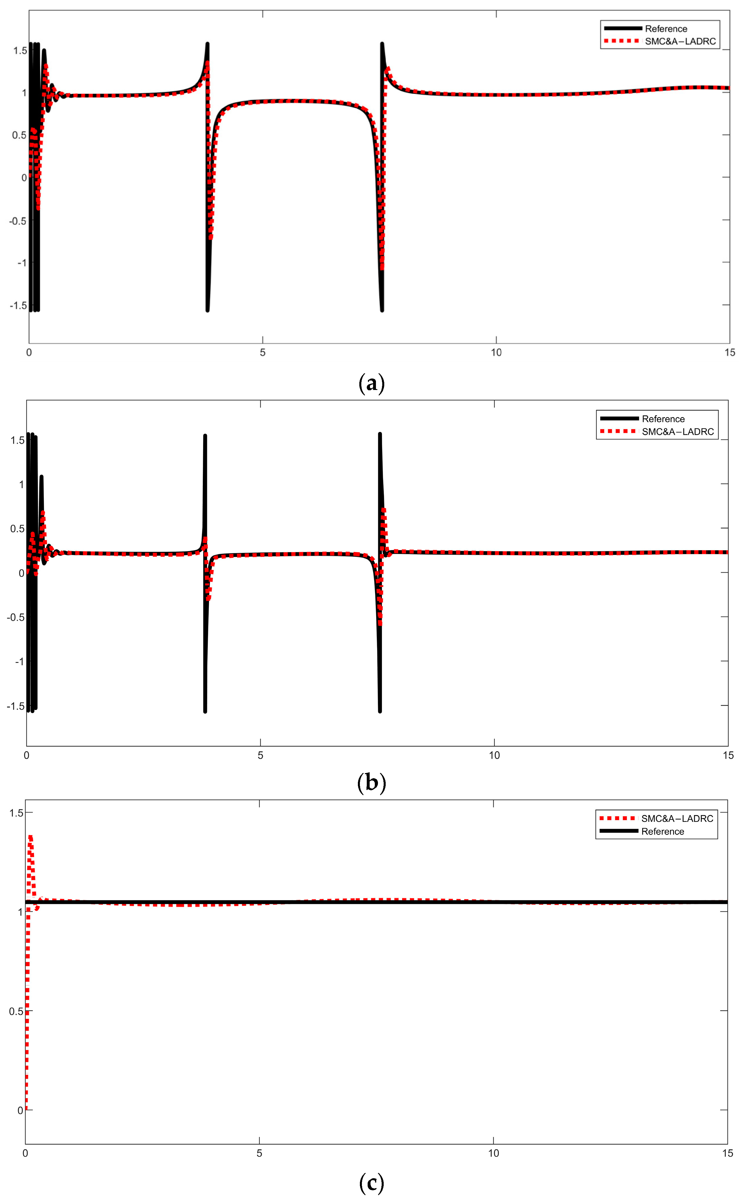
Figure 6a–c, respectively, and it can be seen that the control strategy proposed in this paper can be quickly to the input signal, which proves that the SMC&A-LADRC control scheme is reasonable and effective.
Simulation Example 2. This simulation example is designed to test the robust performance of SMC&A-LADRC with wind disturbance as shown in Equation (38) and input signal as shown in Equation (37) in reference [
30]
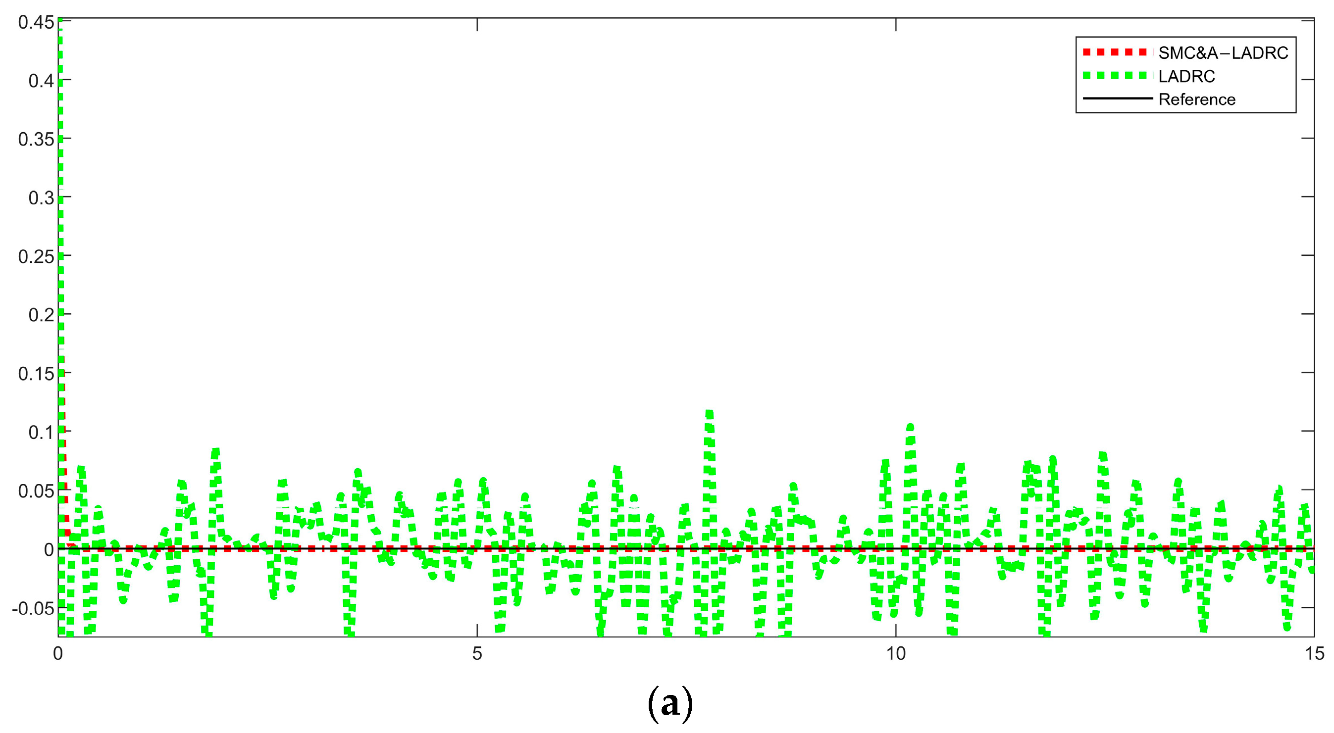
. The position control response curve under perturbation is shown in Figure 7, and Figure 8 represents the error comparison graph between LADRC and SMC&A-LADRC.
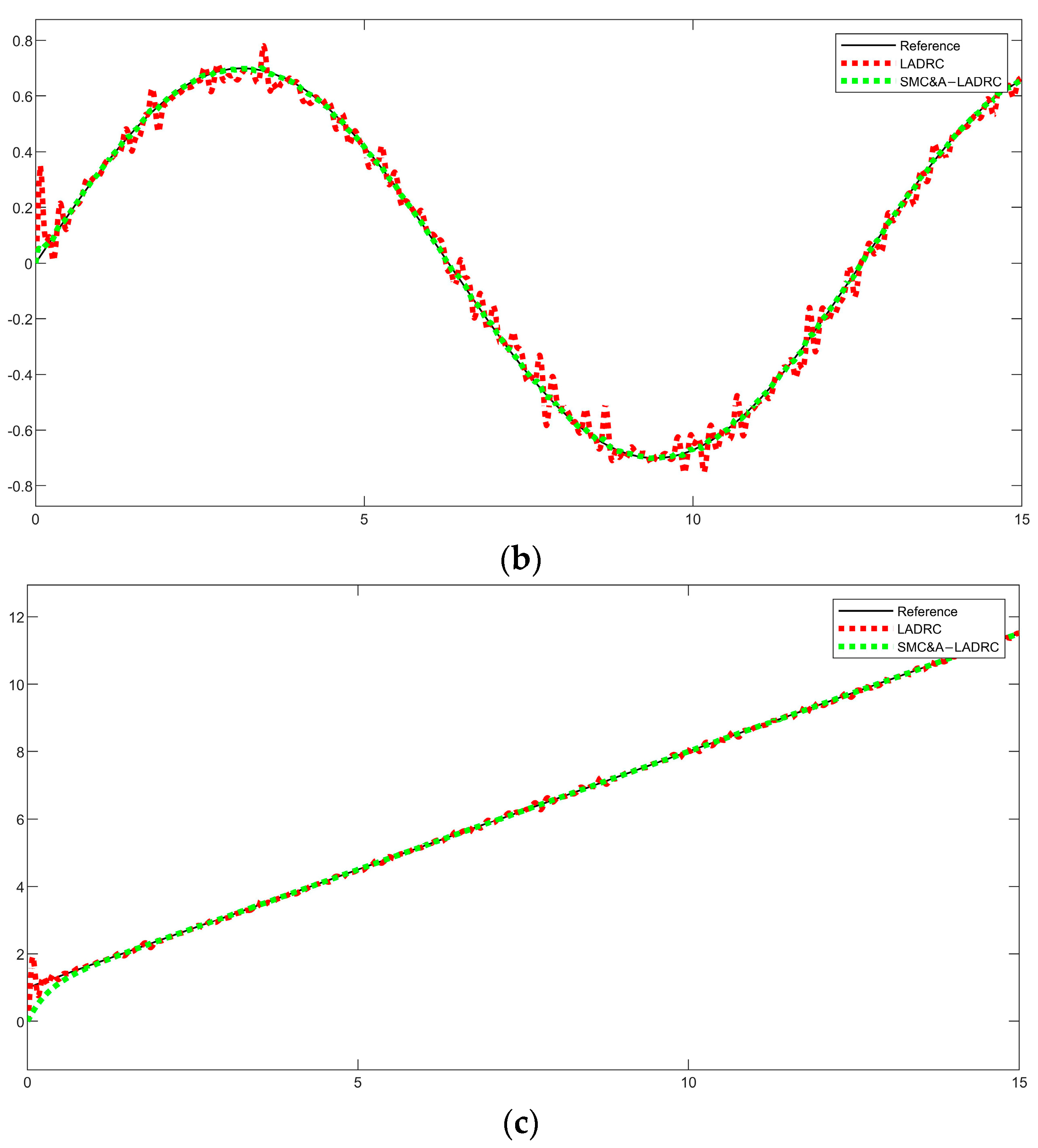
The simulation case 2 is designed to test the robustness of SMC&A-LADRC. In order to achieve the UAV flying on the optimal path, strong wind disturbance is added to six channels in this paper. As shown in the analysis of
Figure 7, SMC&A-LADRC reaches the equilibrium at 0.8 s and the tracking curve is smooth and fits the desired signal, while LADRC has obvious fluctuations in the process of tracking curve.
Figure 8 shows the comparison of the tracking error between SMC&A-LADRC and LADRC position channels, and it is obvious from the figure that the error of SMC&A-LADRC is almost zero after reaching equilibrium, which indicates that the change in strong wind disturbance has little effect on the quadrotor system, and thus shows that the proposed SMC&A-LADRC method has a high robustness, and it can be used in the presence of wind disturbance and internal UAV perturbations; therefore, the quadrotor can be made to fly in the optimal path and achieve energy optimization.
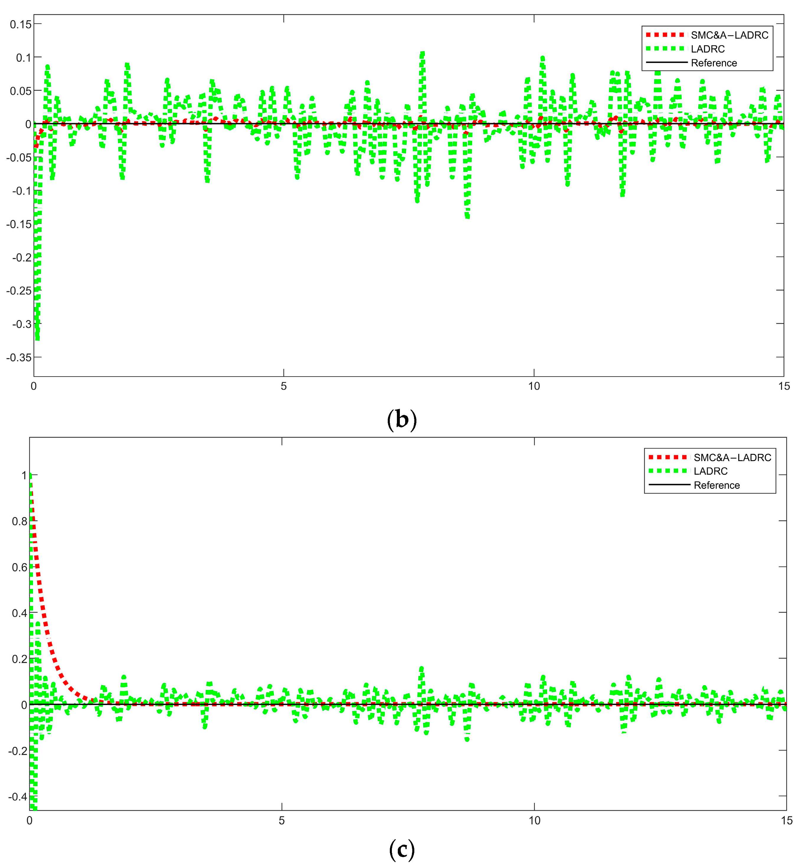
Simulation Example 3. The step input is the most severe operating condition for the system, whose rise time is almost zero, and the frequency band of the signal is inversely proportional to the rise time. In this test, we give the step expectation signal and add the step signal perturbation in the 12th second of the simulation as a way to test the tracking performance and interference immunity of SMC&A-LADRC, giving the step expectation signal as shown in Equation (39): The tracking graph of the position control channel is shown in
Figure 9.
Remark 3. Reference [
22]
proposed a LADRC attitude control scheme with improved fal function; after simulation study, this scheme has less errors than the classical ADRC. Ideally without external disturbances, LADRC can achieve the same smooth curve as SMC&A-LADRC, but the quadrotor UAV will definitely be subject to external disturbances such as air drag and wind disturbances in operation, so comparing SMC&A-LADRC with LADRC can adequately reflect the superiority of the proposed control scheme. Simulation case 3 is to test the control performance of SMC&A-LADRC under severe working conditions.
Figure 9a–c indicate the tracking state of
,
and
channels, respectively; thus, it is obvious that the SMC&A-LADRC controller has reached smoothness at 0.1 s, which is 0.2 s faster than the response under LADRC control, and there is no obvious fluctuation. At 5 s and 10 s, the input signal is in the form of a step signal, changing the desired value, and it is obvious from the graph that there is a significant vibration in LADRC, while the curve of SMC&A-LADRC fluctuates less and is smoother. To verify that SMC&A-LADRC has good robustness, we introduce severe step disturbance at the 12th s. It is obvious from the figure that the proposed control scheme has good anti-disturbance performance.
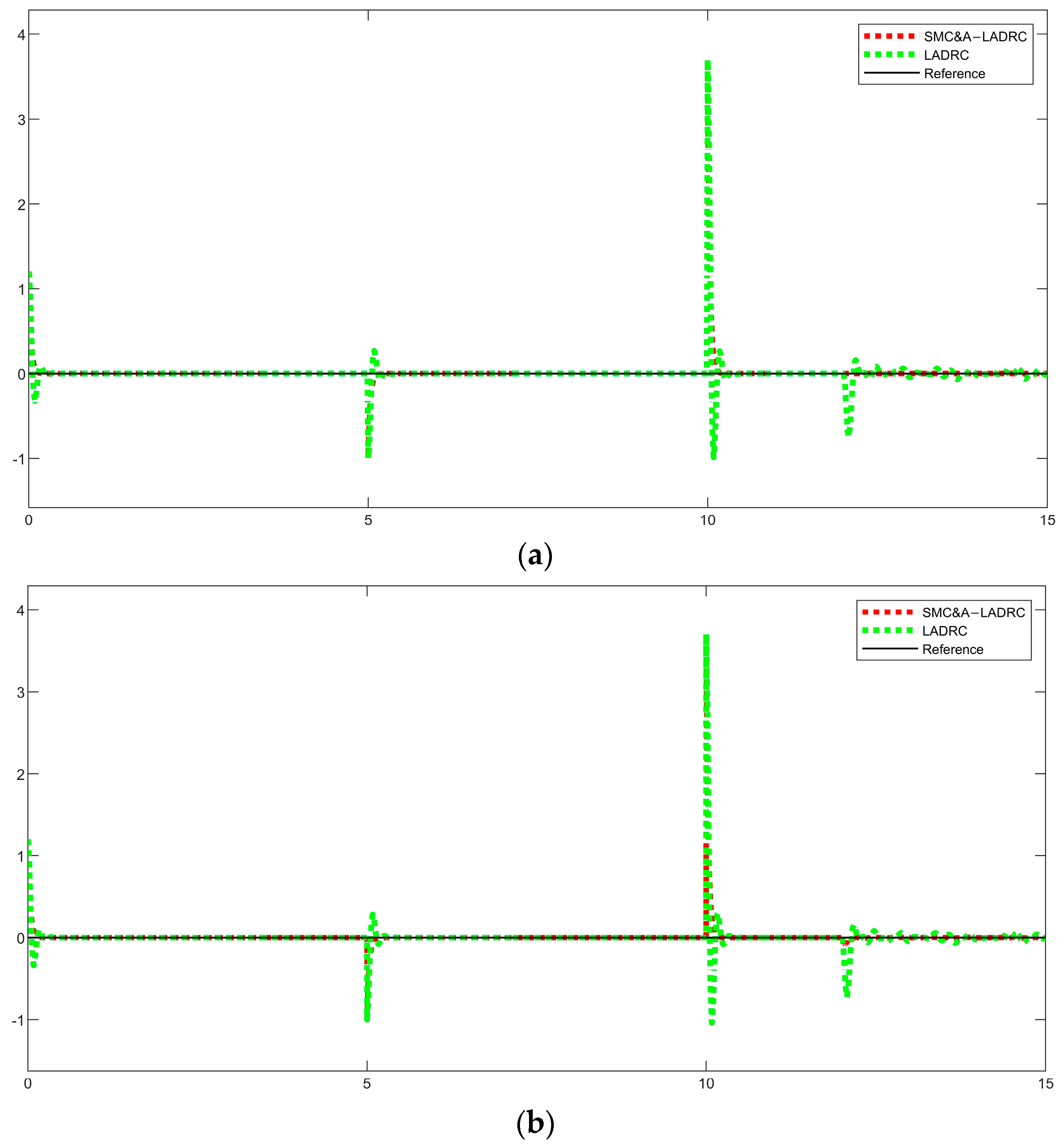
Figure 10 shows the comparison of LADRC and SMC&A-LADRC errors in the saving state. From the figure, it can be seen that the errors of SMC&A-LADRC converge faster than LADRC when subjected to step perturbation and can converge to zero better, which proves that the control scheme proposed in this paper is reasonable and effective. The above shows that SMC&A-LADRC is able to respond quickly to the changes in the input signal, which allows the quadrotor UAV to work with the shortest path and energy optimization to achieve a long-endurance operating mode.
Remark 4. In the comprehensive simulation cases 2 and 3, we designed two different external disturbances to verify the robustness of the control system; one is the gusty wind disturbance that the quadrotor UAV must be subjected to in flight, and the other is a step signal to simulate the uncertain strong external disturbance. Figure 8 and Figure 10 illustrate that if the external noise disturbance is large, the upper bound of the disturbance also needs to be increased, but too large an upper bound may cause jitter or system runaway, which does not guarantee good tracking performance. The introduction of SMC&A-LADRC can reconcile the conflicts between the coupling and immunity performance of each channel of the quadrotor UAV and make the control system more robust, which is a practical control algorithm for quadrotor UAVs with strong external disturbances. Combining all the above simulation cases, simulation case 1 is to verify whether the SMC&A-LADRC control strategy proposed in this paper has good trajectory tracking performance, and simulation cases 2 and 3 are designed with wind disturbance and step disturbance to verify whether the SMC&A-LADRC control strategy has good robustness. Integrating the above estimated tracking diagram and simulation evaluation, we verify the rationality and effectiveness of the SMC&A-LADRC control strategy proposed in this paper, and it has good control performance and strong anti-disturbance capability with stronger robustness when subjected to internal disturbance and external disturbance of the quadrotor, which can make the quadrotor UAV work with the optimal path for flight and achieve the expected control effect.
5. Conclusions
In this paper, a quadrotor mathematical model is established through the conversion relationship between airframe coordinates and fixed coordinates, adaptive control and sliding mode control are introduced to optimize LADRC, and a quadrotor tandem control scheme based on LADRC is designed. The adaptive control can optimize the parameters of PD controller and reduce the tediousness of manual parameter tuning, SMC can eliminate the external disturbance of quadrotor, and combined with the total disturbance estimated by LESO in real time, it can effectively solve the problem of jitter in SMC. Through simulation tests, the control strategy proposed in this paper is proven to be better than LADRC, and is effective and reasonable.
At present, this paper is limited to theoretical analysis without considering some practical problems. Given that position control is the key to the optimal path of a quadcopter, this paper only investigates the quadcopter position control system and does not conduct experiments due to equipment limitations, which is the shortcoming of this paper. The above issues will be considered in the next step of work.


