Review

Flexible Coated Conductive Textiles as Ohmic Heaters in Car Seats

1
Department of Machine Parts and Mechanisms, Faculty of Mechanical Engineering, Technical University of Liberec, 461 17 Liberec, Czech Republic
2
Department of Textile and Materials Engineering, Technical University of Liberec, 460 01 Liberec, Czech Republic
3
Department of Energy Systems Research, Ajou University, Suwon 16499, Republic of Korea
4
Department of Design and Mechanical Elements, University of Zilina, Univerzitná 8215/1, 010 26 Žilina, Slovakia
*
Author to whom correspondence should be addressed.
Appl. Sci. 2023, 13(12), 6874; https://doi.org/10.3390/app13126874
Submission received: 22 March 2023 / Revised: 25 May 2023 / Accepted: 29 May 2023 / Published: 6 June 2023

Abstract

:
Pleasant interior conditions within cars, as well as a comfortable feeling, are primary needs of car drivers to perform vital body functions during driving. In a cooler outer environment, a warming system within seats can quite feasibly maintain a realistic thermal balance in the body. An inbuilt heating system in car seats can not only provide adequate heat to the driver but is also relevant to minimizing the energy consumption within the vehicle interior. In order to evenly distribute the heat over the body contact area of the automotive seats, conductive textiles are proposed. In fact, these textiles behave as a semiconductor (as an electrical conductor and also creating resistance, which in turn creates heat). Flexible textile ohmic heaters present great advantages due to their ability to bend, stretch, and stitch. These properties make them valuable to ensure uniform heaters for irregular geometries. The present review highlights the use of different textile-based ohmic heaters, their fabrication methods, range of heating, and durability. Moreover, this review also focuses on the comparative mechanical performance and comfort properties of the presented fabrics (used in car seats). This study is beneficial for future trends of minimizing energy consumption and providing an effective way to reduce the carbon emissions and air pollution produced by vehicles.

1. Introduction

Recent decades have seen a variety of research in the area of lowering energy consumption due to environmental concerns [1]. The electrification of the vehicle fleet is regarded as a promising strategy for lowering greenhouse gas emissions, energy demand, air pollution, and dependence on oil, among other cutting-edge techniques to decarbonize urban transport [2]. Heated seats in vehicles are one of the primary electric energy consumers in many parts of the world where winters can be relatively cold and long. As a result, the research and development of novel materials and methods that could be more energy efficient has increased [3].
Electric vehicles (EVs) in the transportation sector have the advantages of negligible harmful emissions, low engine noise, improved propulsion efficiency, and the potential for carbon footprint reduction [4]. As a result, most cars, including those that are less expensive, now come with heated car seats as standard [5]. Engine waste heat and electrical resistances are both employed for heating. The subjective comfort sensation is the key problem concern. This varies from person to person, and management is frequently influenced by passengers’ choices. Maintaining the ideal comfort levels for all passengers is a challenge because air is often the medium that transfers heat [6]. Among most potential applications such as weather forecasting, monitoring systems, bio sensors, and electronic sensors [7], the use of conductive fabrics as an ohmic heater in car sears is quite a novel approach. The size conformation, long durability, lightweight property are the key components of conductive textiles which make them an excellent solution in various realizations of platforms for use as ohmic heaters [8].
Resistive heating is the most useful approach adopted in utilizing automobile seats as heaters. A carrier material (a hybrid of textile and foam) is filled with sinusoidal loop-shaped wires between its layers in a seat-heater produced by FOAM-AD. A heating wire is connected to the carriers in a tailored pattern to provide an ideal heating system in the vehicle seat considering the specifications provided by the customer [9]. The wiring pattern is shown in Figure 1.
The wire might be sewn to the continuous non-woven base before the finished product is trimmed into the appropriate shape for a heating mat using automated manufacturing embroidery machinery. For instance, a thin nonwoven layer could be added to a structure made of a narrow sponge shielded with adhesive, the heating element introduced, and the residual adhesive on the mat covered. Another option is to use an automated series of machines where the glue is sprayed upon a non-woven bottom of a pre-defined structure, followed by the placement of the heating wire in the appropriate shape. The multistage method for producing a single mat, the insufficient endurance of anchoring the heating element to the mat foundation, and the inadequate robustness of certain mats for mechanical stress such as loading or abrasion are, nevertheless, the most frequent problems brought up by manufacturers. Wearable thermal technology that utilizes metal wire heating systems has limiting heating regions, poor elasticity, and oxidative deterioration and delivers inefficient heating. It also has a short lifespan due to wire breakage [9,10].
Wearable heating systems must be mechanically durable, lightweight, and able to withstand stretching and bending without obstructing the wearer’s or the garment’s potential to conform to body curvature. The propensity to expand would improve the device’s ability to contour to the body. Stretchable devices must undergo a minimal recurring strain of approximately 15–20% to remain flexible and fit [11]. Graphene inks, carbon-black [12], and blends of silver nanoparticle and laser lowered graphene oxide (GO), along with amino functionalized graphite and carbon nanotubes, have all been used to create flexible imprinted textile heaters. Printed heaters have used tiny carbon heating elements between silver conductors to get around the large sheet resistance of carbon sheets [13]. GNP-only inks are ideal for wearable heating applications, and rigid substrates have been employed in printed heating systems because of their high resistance [14]. The effectiveness of the heat pumps during tensile extensions had not traditionally been evaluated, notwithstanding flex testing. Moreover, it has been demonstrated that commercially available carbon-inks are not sufficiently serviceable against wrinkling and electro–thermal effects [15]. Polymer composites compounds that make up nanofillers have benefits including being lightweight, resistance to corrosion, simple processing methods, degradability, chemical stability, tuneable electrical properties, and lower production costs for electric heater applications [16]. Graphene-based heaters frequently exhibit fast heating rates and uniform temperature delivery [17]. However, because graphene-based heaters generally possess a high sheet resistance, they demand substantial voltage levels for applications which require extreme heat, which could pose an injury risk. As a result, a low resistance heater that operates at lower voltages is preferred [17]. As a result of their minimal sheet resistance, metal nanostructure heating systems could be operated at lower driving voltage levels. The incorporation of electro-conductive features into the fabric structure results in a flexible textile which does not compromise the level of comfort, maintenance, and breathability of the clothing. Electrical heating items, in general, increase the temperature through integrated heating elements. Metal-coated fibers or fabrics are frequently utilized to heat textiles for heat control using various techniques [18].
The current review focuses on the use of various textile-based ohmic heating systems, their fabrication techniques, heating range, and reliability. Furthermore, the review focuses on the mechanical efficiency and comfort features of the described fabrics (used in car seats). This study is useful for future trends in reducing energy consumption, which is an effective strategy for lowering the air pollution and carbon emissions caused by vehicles.

2. Principle of Electrical Resistance Heating in Textiles

Heat is produced when an electric current flows through any conductive material. The electric current that passes through the resistor produces heat depending on its level in an electric resistance heater. However, according to a fundamental concept of Ohm’s law, the voltage and current in the circuit limit the amount of current that can flow [19]. Resistors with specific values can be designed and produced in a variety of sizes and shapes within a fabric. The placement of the resistors on the fabric seems to have no effect on the resistor’s value. The value of the resistance is unaffected by the location of the resistors on the fabric. Conductive pieces can be arranged in parallel and series, regardless of the fabric’s area or surface, to create electrical networks inside or on top of the fabric structure.
The different types of conductive materials provide different ranges of resistance values, that can range from a few ohms to many kilo ohms. Actually, the linear resistance of conductive tracks determines the resistance value of the electrical networks constructed within the fabric structure. Careful attention must be given to the formation and insertion of these conductive tracks in textile-based heating systems, as the manufacturing process could harm them and result in a loss of conductivity [20,21]. Conductive elements can also be arranged in parallel and series to construct electrical network connections inside/over the fabric structure independent of the fabric’s area and surface. Resistance values can range from very few ohms to several kilo ohms which depends on the type of conductive element. The values of resistance for fabric-manufactured electrical systems are described by the linear resistance of conducting yarns/tracks. In the heating systems based on textile materials, the manner in which conductive tracks are created and inserted is crucial since the production process might damage the conducting paths and lower their conductance level [22]. Moreover, the conducting lines used in wearable technology need to be robust enough to prevent breaking and offer effective heating while also being flexible and light enough to bend [23]. Every square centimetre of fabric will release heat in the form of many watts of power, depending on the conductance level of the resistors. Higher power dissipation can be obtained by scaling up the resistor in the fabric area; however, high power dissipation necessitates an increased level of power supply. The electrical systems must be made larger for efficient heat dissipation on a fine surface of textiles. Evidently, one of the key considerations in designing an effective heating system is the efficiency level in removing the heat owing to the electrical core network on the fabric [24]. In rechargeable batteries-based portable electronics, specifying the necessary wattage value instead of the rated voltage allows for a greater design flexibility in the heating system. In order to calculate the required amount of distance for including conductive threads or tracks and, in turn, the measurements of textile-based heating systems, it may be more flexible to assess the watts value with a specified electrical resistance of the conductor [24].

3. Metal-Coated Electrically Conductive Heating Textiles

Electrically conductive fabrics and yarns are the key components of heat-producing textiles. The incorporation and coating of conductive material (metals and carbon-based) are used to fabricate electrically conductive textiles. The choice of metal-coating strategy for the manufacturing of conductive fabrics is critical in terms of processing parameters that tend to be associated with economic attractiveness and determine the reliability, flexibility, physiological, and electrical properties of end e-textiles [25]. In particular, there are two methods for producing conductive textiles. The first method involves weaving, knitting, or embroidering conductive fibres, threads, or yarns into fabrics. Nevertheless, these techniques are highly complex, and because the fabric is hard and inflexible due to the implanted electrical fibres or threads, it may not be comfortable to wear [26]. The typical method entails coating the surfaces of fabrics with robust electrically conducting materials (conductive nanoparticles, metals, and conductive metals, etc.) using a variety of coating techniques in order to give the textiles their electric properties throughout the finishing process. The incorporation of different metals on surface of the fabric (a process known as metallization) has drawn considerable interest among the various techniques employed to attain conductivity for their distinctive properties in offering multifunctional performance, including EMI shielding, antimicrobial activities, fungicidal activity, electrical properties, and ohmic heating [9], in addition to a lustrous metallic visual appeal for aesthetic reasons. The most popular techniques for metallizing textiles can be subdivided as follows (Figure 2) [27]:
(i) Metallic inks are printed on surfaces using a lithographic technique, inkjet, screen printing, and stencils;
(ii) Deposition (electrochemical, chemical and physical vapour, electroless);
(iii) Spray coating (thermal, plasma-assisted cold, etc.).
The appropriate method is determined by several parameters, including the form and type of textile material, operating temperature, metal type, and end application, which is also related to the required thickness of the layer of conductive material [27].

4. Metal-Coating Techniques

4.1. Electroless Plating
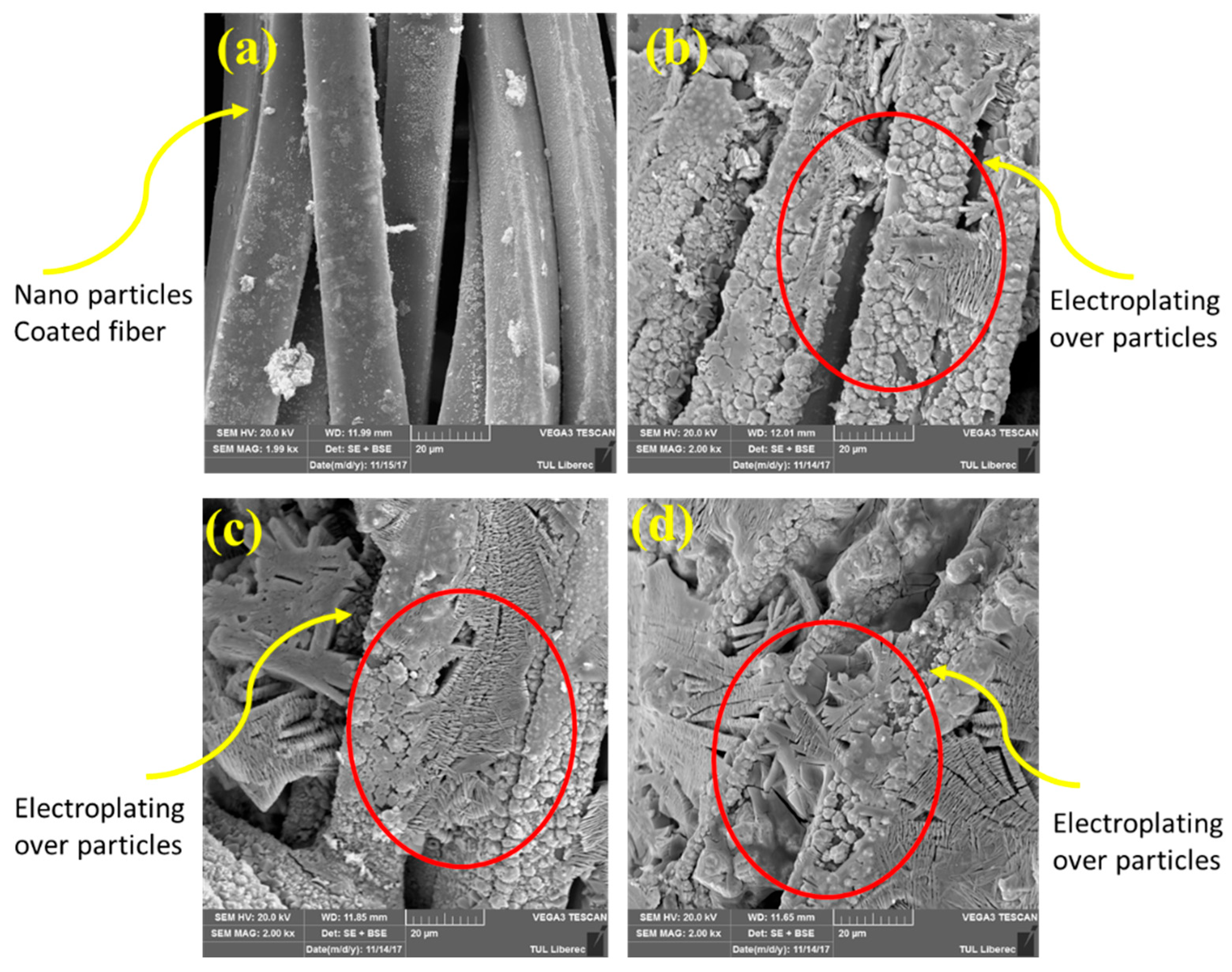
Electroless plating is an established controllable method in which single metallic nanoparticles such as silver (Ag), copper (Cu) [28,29], nickel (Ni) [29,30], gold (Au) [30], palladium (Pd) [31], platinum (Pt) [32], and or poly-alloys such as Ni-W, Cu-Ni, and others are chemically deposited onto non-conductive (dielectric) materials (plastic, printed circuit boards, ceramics, glass, and textiles) from an aqueous solution to develop a conductive layer of metals. Figure 3 shows the deposition of a conductive layer of copper and silver particles and the deposition of nickel over the textile structure. Furthermore, the electroless-plating process can be applied to multiple kinds (synthetic and natural) and forms of textiles, such as fibres, yarns, and plain fabrics (non-woven, woven, or knitted) [33]. According to Zhang et al. [34], non-diffusive copper (II) imprinting with a viscous fluid Cu (OH)2 solution followed by Cu deposition on fabric by utilising various reducing agents is able to produce well-defined and extremely well-conducting patterns on cotton. Wills et al. [35] produced a precise structure of silver NPs to function as a catalyst on cotton using ink-jet and micro-dispensing printers, followed by electroless plating of copper (patent pending). Wu et al. [36] developed a method for the fabrication of a stainless-steel stencil mask with the required design on top of the fabric to create textured electrodes for light-emitting e-textiles (signalisation, entertainment, and fashion, etc.). According to Hu et al. [1], screen printing a dopamine surface modification followed by electroless silver plating allowed for the development of a precisely articulated Ag conducting network on PES fabrics [35,37].

4.2. Electroplating

Electroplating is the process of coating a thin metal layer of reduced metal with the help of an electric current on a conductive substrate. Prior to plating, the substrate should be cleaned to eliminate contamination, bringing about effective attachment of the metal particles to the surface. In general, there are three main phases during cathodic metal deposition: (i) ion migration, (ii) intercalation of adsorbed metal ions, and (iii) electron transfer [38]. The electrochemical deposition has several advantages such as controlling the thickness and morphologies of the deposited metal, and controlling the parameters of plating (time, temperature, and concentration). Additionally, the process only requires low-cost equipment, which makes the process economical and easy [39]. The main drawback during electroplating is that the targeted substrate being plated must already be electrically conductive enough for current to flow through it. Hence, there is a need to activate the textile or polymers prior to electroplating, as they typically function as natural insulators. The non-conductive substrate is normally activated by the making of conductive layers (in a pre-treatment step) on a material surface, utilizing various metals, for example, Ag [40,41], Cu [33,42], Ni [43], Mxenes [44], Ni–Co selenide nanowires [45], NiMoO4/CoMoO4 nanorods [46], LaMnO3/MnO nanoarrays, ZnO nanostructures stored on a Ni–CuNi conductive layer [47], and LiMn2O4 [48], conductive polymers [49], or carbon-based materials [50]. Figure 4 shows the flow of the electroplating deposition process. The substrate is activated by a metallic nanolayer of Ni3Se2 onto the PES texture, utilizing a three-cathode framework [51].
Cu is one of the most mind-blowing metals for the pre-treatment of material substrates, since it usually covers minor imperfections. As a result of electrodeposition, it is fairly lethargic, has a negligible cost and a high declaration viability, and is significantly conductive [52]. Utilizing a Cu-polythiophene composite film as a seed layer for direct electrodeposition, bringing about a stretchy texture with a high electrical dependability for observation, Ali et al. investigated the in situ deposition of Cu particles on cotton fabric [53] due to its potential to shield electromagnetic interference. They discovered that 100- and 150-plunge textures with a thick, uniform, and permeated organization of conductive Cu particles on a superficial level displayed the highest level of protection, 10 dB. Zhao et al. utilized flexible polyaniline/polyethylene terephthalate (PANI/PET) conductive textiles made by chemically polymerizing PANI on PET textiles and electrochemically depositing Cu crystals for potential e-textile applications [54]. Cu was recently deposited using a new technology called hydrogen evolution-assisted electroplating, which improved deposition rates compared to the conventional electroplating method [55]. Cheng et al. reported the use of in situ hydrothermal growth of Cu NPs, with a polydopamine-pre-treated PET knitted fabric as a template. During the long-term cycle test, the resistance-strain behaviour was extremely stable. The planned framework showed its appropriateness for use as a wearable strain sensor, for example, to recognize ongoing biceps brachii motion, shank walking, subtle body deformation, muscle movements during swallowing, etc., as well as electric heaters available for use in thermal therapy.
Azam et al. fabricated a more compact layer of copper deposition over the textile fabrics. As shown in Figure 5, the textile cotton–nylon blended fabrics were activated with copper nanoparticles and subsequently copper plating was performed [56]. Electroplating was performed with power rated at 24 V/2 A with a consistent current flow of 1.9 ± 0.1 A. The conductive copper rod was attached at the anode, while the copper-particle-coated fabric (substrate being plated) was attached at the cathode. By applying a voltage difference across the fabric while measuring the temperature change at its surface, the fabrics’ heating properties were examined [56].
SEM images of fabrics are depicted, showing the more dense and uniform deposition of Cu-NPs prior to further copper plating. The final copper-plated fabric is depicted, showing the thicker layer of Cu with extra electroplating and plated copper morphologies showing the orbicular structure similar to a crocodile-skin surface [56].

4.3. Printing of Metallic Ink

The ability to deposit conducting materials on various textile surfaces at room temperature, the capacity for obtaining well-defined conductive visuals or designs, the reduction in the use of conductive inks, the transfer of the complete method to the industrial sector, the possibility of mass production, and cost efficiency are just a few advantages which printing has above other techniques that provide electrical properties. Silver and gold are two of the metals that are most abundantly observed in metallic conducting inks [57]. Silver-based inks progressively oxidise on the substrate, generating a tiny conducting oxide coating that over time has no impact on the conductance of the ink. As a result, several companies (DycoTec, Henkel, DuPont, NovaCentrix, and others) have developed and marketed silver-based inks, such as the Intexar-TM fitness able to monitor a T-shirt with Wi-Fi interconnection (DuPont). On the other hand, a high silver loading (greater than 20 wt%) is needed for metal-based inks [41], so the key challenge is to obtain a less expensive but super effective conductive metal to substitute the silver nanoparticles [58].

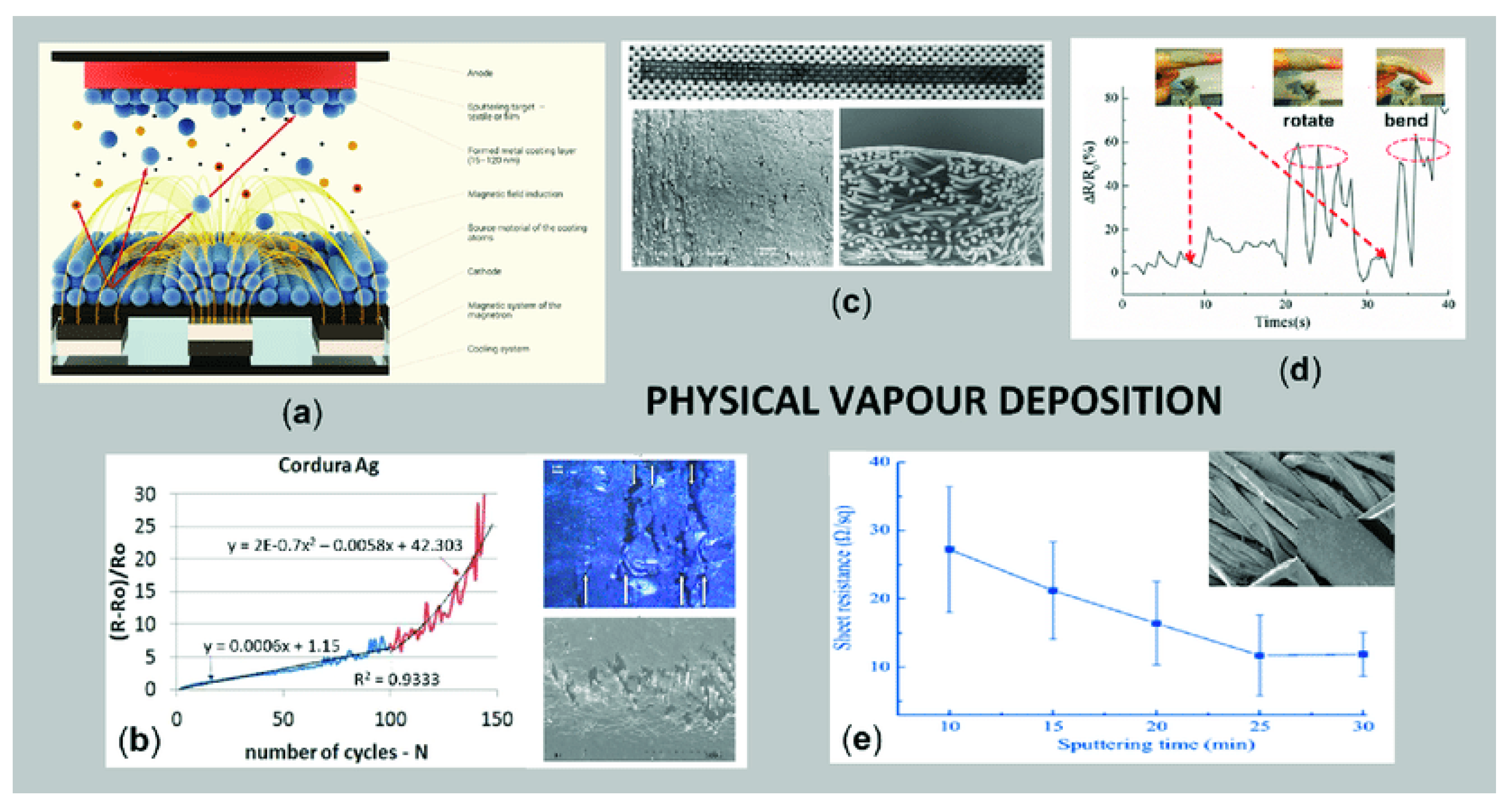
4.4. Vapour-Deposition Techniques

Vapour deposition is an atomistic deposition method in which the coating materials are vapourised and condensed in a vacuum onto the selected substrate, producing a thin film from virtually all inorganic (compounds, metals, alloys, and mixtures), as well as certain organic materials [59]. The depositing components are evaporated and condensed in a vacuum onto the chosen surface. The two most common solvent-free vacuum deposition techniques are chemical vapour deposition (CVD), in which the surfaces of coated materials and volatile substrates react, and physical vapour deposition (PVD), during which sputtering and evaporation take place. Both CVD and PVD have opened up new possibilities for textile material modification, and they represent an intriguing prospect for the development of e-textiles. The transport of precursors into the reactor, the diffusion of precursors to the surface, the adsorption of precursors on the surface, surface reactions such as the decomposition of precursors on the surface and integration into a solid layer, and the desorption and conjugation of molecular by-products into the gaseous state are all process steps in CVD [60]. The temperature has a significant impact on the reaction mechanism that proceeds when the precursor gases pass over through the heated surface layer. This solid phase is then deposited across the substrate surfaces. The use of substrates that are mainly composed of metals and pure gases instead of their pricey, complex, and frequently toxic chemicals gives PVD significant advantages above other deposition techniques (including CVD), including good quality, efficiency, and excellent biocompatibility. PVD also has the capacity to generate composite coatings. Pulsed-laser deposition, evaporative deposition, physical vapour deposition involving electron beams, sputter deposition, and cathodic arc deposition are among the PVD types employed for textile alteration. The most popular technique for depositing thin, long-lasting layers of metals (Ag, Al, Pt, Ni, Cu, Sn, Ti), metal oxides (Fe2O3, WO3, TiO2, ZnO), or non-metallic derivatives (silicon, graphite, ceramic) over a variety of kinds and patterns of flat textile materials is magnetron sputtering [61]. Figure 6 depicts the basic pathway of the magnetron-sputtering method [62].
Huang et al. [63] presented the ohmic heating potential, electrical conductivity, and UV-resistance of a nano-Cu film deposited on a polyester fabric surface by using the magnetron-sputtering method with pure Ag and Cu targets in the presence of argon gas. Chu et al. [64] established conducting PP fibres that are simple to work with and long-lasting. These fibres are ideal for joule heating, EMI shielding, and susceptibility to antimicrobial activity, among other purposes. Meng et al. [65] used low-temperature plasma and RF magnetron-sputtering technologies to manufacture copper coatings on polyester surfaces, and they examined how the ambient environment affected the conductance of those coatings. The findings indicated that Cu films were broken and sample stability was lost after 60 days, but the ohmic heating of the samples barely improved with temperature, the intensity of repeated washing, or moisture levels, which are mainly affected by the structural characteristics of substrates. Furthermore, high conductivity ohmic heated fabrics are developed through a variety of two-step processes that incorporate magnetron sputtering and pre-treatment. He et al. [62] fabricated a highly conductive cotton fabric through in situ polymerisation of PPy, followed by direct current magnetron sputtering of a silver thin film. The obtained Ag/PPy-coated cotton fabrics deposited with a sputtering power of 200 W for 25 min seemed to have the maximum electrical conductivity with an average resistive heating of 89 °C. It also had an excellent hydrophobicity, heat resistance, electromechanical effectiveness, and washing durability [62].

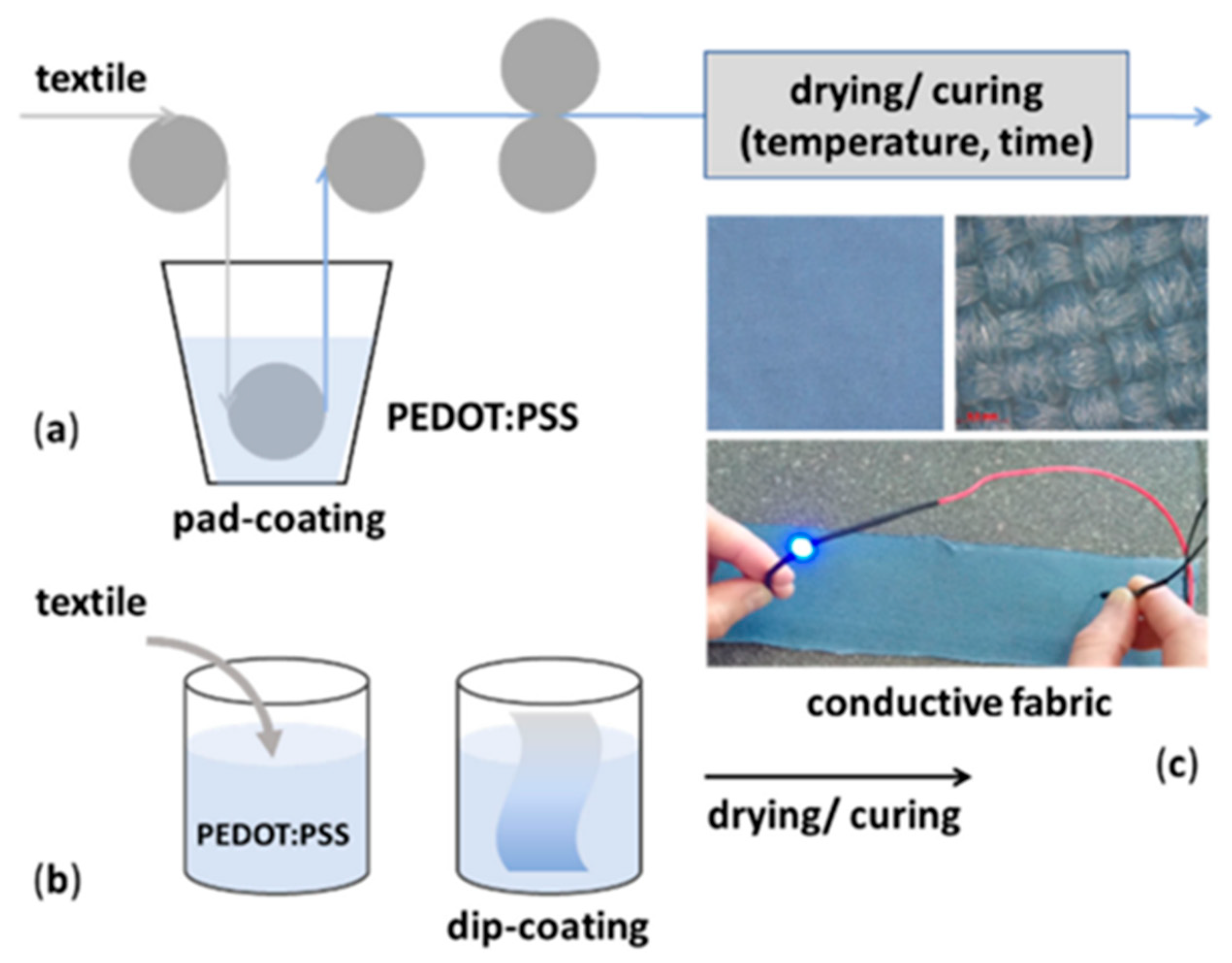
4.5. Dip-Coating Techniques

Dip-coating (or pad-coating) is relatively simple, low-cost, and scalable; thus, it is a widely used fabrication technique used to apply conductive (nano) materials onto fibres, yarns, or fabrics, as it does not require any special or expensive equipment [66]. The entire process can be continuous, as presented in Figure 7a, or discontinuous (Figure 7b). It involves the immersion of the fibrous substrate for a short period into the respective aqueous-based coating solution, which, in the case of conductive textiles’ processing, contains different types of conductive compounds, i.e., electro conductive polymers, carbon-based structures, inorganic metallic (nano)structures, or their combinations [67]. Thereby, the conductive compound is deposited on both sides, over the whole surface [68].
After depositing the conductive solution onto the fibrous material, the drying phase is carried out at temperatures of 110 °C up to 180 °C for a short time period (3 to 15 min), using hot air or infra-red (IR) heating. This process is also known as a curing, during which the excess solvent evaporates and the conductive (nano)compounds fix/crosslink permanently to the textile’s surface, ensuring a stable coating [69]. In fact, the dip/dry cycles can be repeated several times, with the aim of increasing the amount of deposited conductive material (the so-called multi-layered dip-coating method). Moreover, the drying temperature versus time should be considered to prevent damage of the basic textile material [70]. The main disadvantage of the dip-coating procedure is the variance in the smoothness/roughness of the textile’s surface and the uniformity of the applied conductive layer(s), affecting the variation in electrical resistance [71]. The thickness of the layers cannot be fully controlled, since it depends on the surface morphology and the tension of the textile substrate, as well as on processing parameters such as time, temperature, withdrawal speed, compound concentration, composition of the coating bath, etc. [72]. As mentioned above, numerous electro conductive compounds can be applied to fibres/yarns/fabrics by employing the dip-coating technique. In the following sub-sections, the most used materials are presented, as well as different applications [73].

5. Carbon-Based Heating Textiles

Carbon-based conductive materials are an excellent source of heat generation. Graphite powder, carbon nanotubes (CNTs), and graphene are typically adhered to the fibre surface to render it conductive. It is also feasible to develop conductive heating textiles by immersing and depositing carbon nanotubes in cotton while utilising recycled carbon fibre as a dispersion method [74]. In order to enhance the fabric’s thermal properties, MWCNTs are deposited on cotton using impregnation-drying coating techniques, and a rise in specific heat has been reported. Figure 8 shows time–temperature curves for elastic MXene-decorated textiles with interlaced conducting nanostructures for an integral Joule heater with varied heat resistance and voltage. Cotton fabrics coated with reduced graphene oxide (rGO) nanosheet films are being used to manufacture conductive fabrics for heat-generation applications [75]. Wearable electronics, smart devices for personal heating and cooling, or entire personal thermal management (PTM) electronics can be produced by embedding graphene in textiles. Breathability and stretchability can be easily increased by using high conductivity graphene fibres with excellent heating at low energies [76,77,78]. Figure 9 shows IR pictures of a polymer/graphene-treated textile-based multi-layered heating element with aramid fabric along with the surface temperatures of triple and quadruple layers at various power levels [78,79].

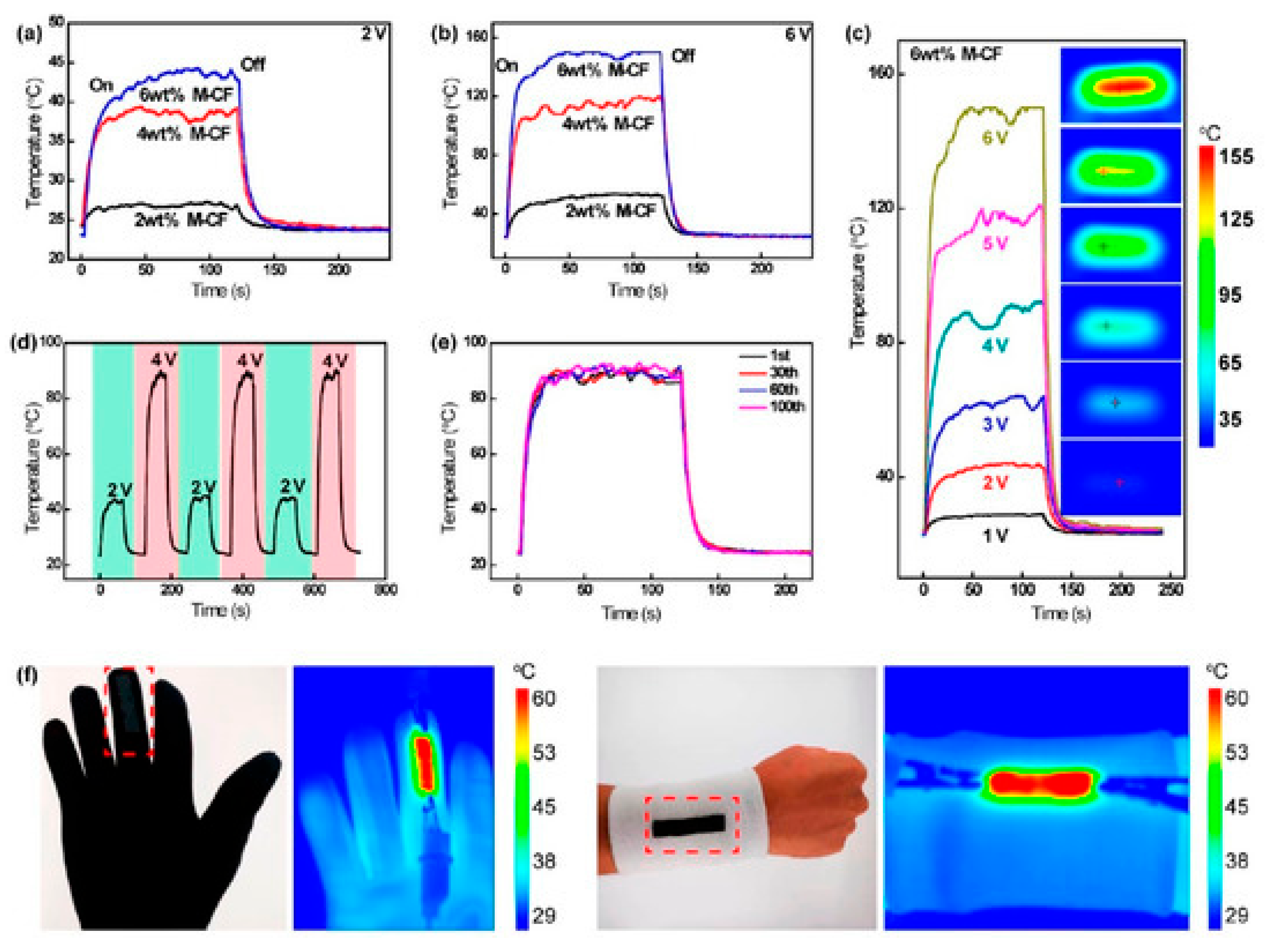
6. Design of Heating Fabrics Seats and Thermo-Electric Response

Heated textiles can be made in two ways: one by fabricating a piece of fabric and inserting an electronic framework into it, and the other by producing a yarn with electronic properties and developing textile products. Metallic wires were first utilized in textile clothing during World War II. Then, instead of metallic wires, more sophisticated conductive yarns with textile yarn characteristics began to be developed. Heating products can be made from knitted, non-woven, woven, and embroidered fabrics. Due to their high resistance, non-woven fabric heating components are only occasionally used. Woven fabrics exhibit significantly less resistance when compared to knitted textile fibres in the same geometrically heated area due to their structural differences [81]. Multifilament carbon-blended stainless-steel fibres with a mild resistance are being developed for appropriate heat-generating applications. According to reports, this particular variety of electro-conductive fibre is exceptionally inflexible and fragile in bending, which renders it inappropriate for textile applications [82].
The standard fabric architecture, including plain, twill-weave patterns or single jersey, interweave, etc., with a standard fabric GSM of 250 g/m2, could be specified for flexible heating inside a textile structure. The fibre composition influences the system’s washability and heating behaviour. Wool fabric, for example, has a higher heating performance than cotton fabric. As a consequence, the thermal efficiency of a textile-based electrical heating network appears to be lower than that of woollen materials if cotton is employed as the basis fabric for the electrical transmission system. As a result, selecting an appropriate fibre composition has a significant impact on the heating efficiency of the system. Overall, the area demanding heat must be enclosed with a flexible surface for efficient thermal effectiveness as a result of delivery via convection and conduction mechanisms [83]. Thus, textile-based electrical heating systems offer a major advantage in sustaining the human body’s essential necessary heat levels by permitting greater contact with the flexible architecture and reducing heat loss. In addition, recent research on textile-based electrothermal networks has attempted to develop a product that can control and monitor body temperature in response to environmental change, particularly for outdoor sports such as skiing and snowboarding. The Ag-coated nylon yarns were stitched over the polyester base-fabric in parallel connection that can provide a parallel power supply for the fabrication of electrically heating fabrics. The subsequent resistance of the design is lower when connected in parallel, allowing it to generate huge heating effects. An additional weave was provided in serial fashion to connect with the power supply [84].
A further experimental process of the study was carried out at Ghent University’s Centre for Textile Science and Engineering for the fabrication of heating mats. They produced distance fabrics with an electrically conducting heating source that could be produced in a single manufacturing method on a warp knitting machine. The design process clearly described the key parameters required for the calculation process, including the full length of the heating mats, the quantity of heat sources, and their length, as well as the exact trajectory. The desired heating mats were 50 cm by 30 cm in size. The current study included three design steps: (i) preparing the movement patterns of heating wires, (ii) estimating the resistance required to calculate the approximate power of the entire mat, and (iii) preparing and testing samples. The detailed methodologies for these steps are described below. At the moment, the sources of power used in cars typically provide a voltage of 12 V, while those used in large trucks provide a voltage of 24 V. Heating element samples of carbon fabric yarn with the placement of the thermocouple for central temperature measurements inside the samples are shown in Figure 10 [84].
Low-voltage equipment was utilised (having a maximum tendency to supply 12 V), and the power was rated at 40 W. The dimensions of the samples were maintained at 10 × 10 cm (Figure 11) [86]. Multiple strategies were used during each testing step in order to maximise thermal efficiency. In the very first step, the heating accuracy, as well as the lowest and highest temperatures within each sample, was taken into consideration when evaluating five patterns in the form of samples. The range of temperature noted for each sample is shown in Figure 11. The pictures were recorded by an infrared camera associated with the FLIR Research IR software program [86].
Azam et al. [56] proposed a simple method for producing electrically conductive multifunctional textiles through embedding them with copper oxide nanoparticles followed by electroplating with copper. The surface and ageing characteristics of a fabric coated with copper nanoparticles were examined. Furthermore, ageing property issues were addressed in a very simple manner, and different functional properties were investigated. The effects of electroplating variables (acid concentration) on the fabric stretch rate were also investigated. The fabric coated in copper oxide nanoparticles was used as a substrate. In 1 L of distilled water, 250 g of copper (II) sulphate pentahydrate (CuSO4.5H2O) was solubilized. Then, gradually, 70 g of 95% conc. H2SO4 was added. The results indicated that the electrical power source had a rating of 24 V/2 A. A continuous voltage with current of 1.9 V ± 0.1 A was maintained across the electroplating procedure. The cathode was joined to the conductive fabric (covered with copper nanoparticles), which was used to deposit Cu metal, whereas the anode was coupled to a Cu plate that functioned as a reservoir of Cu metal. The solution was made to circulate continuously in the electroplating chamber. The heating characteristics of the fabrics treated with Cu nanoparticles and fabric samples electroplated with Cu were assessed (Figure 11). The conducting fabric samples displayed the highest surface temperatures of 127, 108, and 94.8 °C for copper-plated fabric samples (S3, S6, and S9) and 72.6 °C for fabrics treated solely with copper oxide NPs at 5 V and with a time interval of 1 min, respectively. As a result, the developed fabrics performed well in terms of heat supply. These fabrics are suitable for thermal applications in cold environments [87].
Zinc oxide (ZnO) nano-whiskers (NWs) were incorporated into the carbon fibre (CF) surface in order to evaluate changes in mechanical properties and ohmic heating for carbon-fabric-reinforced–green-epoxy composites. The ZnO-NWs have been hydrothermally synthesized onto the CF surface in order to create laminated composites that possess various proportions of carbon weave sheets. The electrical energy performance, highest temperature, and temperature-response rate were computed by a three-part analysis of the temperature versus time curve to explore the resistive heating performance of the laminated composites. Later, the impacts of ohmic heating behaviour on the structural collapse and mechanical properties of the composite materials were examined using dynamic mechanical analysis and X-ray micro computed tomography [88].
A test setup with a power source and an IR camera (865Testo UK) was used to observe the heating properties of laminated composites (Figure 12). The electrodes were kept 7 cm apart by having the power supply fastened to CF at two of the composite’s edges. The IR camera recorded the temperature in the centre of each composite during the heating process while being placed 10 cm above the surface. Prior to further analysis, all samples, identified as CH1, WH1, CH2, WH2, WH3, and CH3, were continuously heated for 10 h at 3 V to study heat ageing.
The carbon nanotube (CNT) layer on the nylon yarn makes it an excellent conductor of electricity and heat. The goal of this research was to coat the CNT with Nylon 6/Spandex yarn to produce electrical conductivity. SEM analysis was used to investigate the physical properties of CNTs. The electrical properties of yarns coated with CNTs in stretched and relaxed states were explored. The conductive yarns revealed a poor resistance when subjected to a high stretch load. Moreover, the heating efficiency of the yarns coated with CNTs was investigated by applying a variety of voltages to the yarn’s surface. The maximum temperature was around 280 °C when the voltage was 5 V for 60 min [89]. Nylon6/Spandex yarns were treated with a sodium hydroxide solution containing CTAB as the dispersing agent. Then, 1 g/LCTAB and 5 g/L NaOH were combined to produce the solution at room temperature. The prepared solution was then dipped into Nylon6/Spandex yarn, and the M: L (material to liquor) ratio was set at 1:40. For 1 h, the entire assembly was heated to 60 °C. Following that, the yarn was thoroughly rinsed with distilled water and dried. In the second stage, 1 g of CNT was mixed with 0.5 g/L of deionized water dye solution. The mixture was sonicated in a (BANDLIN, SONOPULS) sonicator for 60 min [90]. Every hour, the solution’s conductivity was tested, and its pH was also adjusted (by adding acetic acid dropwise). The pH and electrical conductivity of the solution were measured continuously until constant conductivity values were attained. As a result, the pH was adjusted to 6.5 using acetic acid. The alkali-treated yarn was then immersed and placed in a CNT dispersion for half an hour at room temperature before drying at 50 °C. Dipping in solution and drying were performed indefinitely for 5, 10, 15, and 20 cycles, respectively, to improve CNT loading. Finally, the yarns were post-cured in an oven at 180 °C for an hour. Figure 13 depicts the entire process involved in the application of CNTs to the yarns. The production and passage of charge during CNT development stimulates the additional electrons. Electrostatic interaction is the most likely type of interaction between polyamide and CNTs since the majority of polyamides are positively charged [91]. Table 1 provides an overview of the most recent studies.
Michael Weiss et al. invented a seat heater based on flexible carbon conductive fabrics. They employed a textile sheet made up of carbon electrically conductive fibers as heating elements. As a result of its design, this technology guarantees a very homogenous distribution of thermal output, in addition to the advantage of greater mechanical comfort. It is possible to warm seats extremely uniformly with the aid of these well-known seat warmers, resulting in a pleasant temperature and eliminating any noticeable temperature variations in the seat. Despite having a set thermal capacity, these well-known seat heaters cannot rapidly reach this condition given the provided value of the seat’s thermal capacity due to the heaters’ total power requirements. Furthermore, a “quick-heating eld” is created by the unique characteristic for heating a specific portion of the sheet-type heating element with a higher heating density. This causes the thermal energy to focus on a small section of the entire seat, resulting in faster warming in that area. Therefore, the warming process will be felt by the passenger much more rapidly, for example, within the first few seconds after turning on the heater. The lower thermal output from the adjacent seat areas will not be bothersome. The following Figure 14A,B show a description of the designed seat heaters where the carbon-based conductive fabrics are connected with heating elements and electrodes [95].
Figure 14A provides an illustration of a seat heater 60 featuring a pre-designed sheet-type heating element 62. This type of heating element is made up of electrodes 64A through 64G which are woven in the longitudinal direction of the sheet-type heating element 62, spaced apart from and parallel to one another. The sheet-type heating element 62 has a groove 66 between the two outer electrodes 64A and 64G for electric separation. This groove runs transverse to the electrodes. In addition, the electrodes 64C and 64E are separated in the area of the groove 66 to create additional electrodes. The seat heater 60 can be operated in such a way that a spatial concentration of thermal output is produced thanks to the electric separation of the sheet-type heating element 62 based on the groove 66 and separation of the electrodes 64C and 64E. A sheet-type heating element 72 composed of woven carbon fibre filaments, with one main electrode positioned on each of their opposing longitudinal sides, is included in the seat heater 70 seen in Figure 15B. A quick heating element 74, which affects only a small area of the entire surface, is attached to the centre of the sheet-type heating element 72 using traditional strand technology. Two additional electrodes 76A and 76B connect to the rapid heating element 74, in which one electrically insulated heating region runs directly on the sheet-type heating element 72 in a very straightforward strand running configuration. This allows for both a solid integration of the two sheet-type heating components 72 and 74, as well as a sample design. Activation of the quick heating element 74 via the additional electrodes 76A and 76B is independent of the overall heating mode that uses the main electrodes 18A and 18B. While the lines to the additional electrodes 18A and 18B are labelled 24A and 24B, the lines to the main electrodes 13A and 13B are marked as 22A and 22B [95].
In order to evenly distribute the heat over the body-contact area of the automotive seats, Vinko et al. [96] planned to apply the heating coatings to the bottom of the textile over the whole sitting area of the seat. They studied the fabrication and properties of the heating fabric material covered with carbon single-walled nanotubes based on a composite coating using screen printing. The effects of various formulations and additions, including silver nanoparticles and highly electrically conductive polyaniline fibres, were investigated. To enhance the material’s antibacterial properties, silver was added. Three different fabric types: leather, cotton canvas, and synthetic leather, that are frequently used in the manufacture of automotive seats were coated with composite materials. The thickness (number) of the coatings allowed for customization of the electrical conductivity and, as a result, the heating characteristics. As a function of the tensile strain that certain materials are typically subjected to during usage, the electrical characteristics were measured. Additionally investigated were the heating rate and temperature consistency across the entire heated area. Table 2 provides a summary of the materials’ characteristics, and Figure 15 shows optical micrographs of the top surfaces [96].
The homogeneity of the surface temperature is one of the crucial factors in determining the potential practical application of this type of heating textile. The temperature gradients on the leather, cotton canvas and artificial leather sample’s surface during the heating process were analysed using a calibrated IR camera. The heating response of all the samples observed with IR camera are showed in Figure 15d,e,f tracked the samples’ gradual heating using the surface IR pictures (Figure 15). The sample began to heat rapidly near the electrical contacts during the initial stage of heating, peak temperatures began to enter the sample’s interior during the intermediate stage, and by the time the heating process was complete, the temperature in the heated area was more-or-less uniform (within a few °C). The study results indicate the importance of using large electrodes that span the entire sample’s edges for optimal performance [96].

7. Future Prospective of Conductive Textiles in the Automotive Industry

Electrically conductive textiles are constantly being brought into the automotive field. The future trend is the use of textile-based sensors, enabling non-driving activities integrated in the car interior and supporting a richer user experience. Automobile designers are focusing on the integration of lightweight and multifunctional smart textiles in car interiors. For instance, the demand of electrically conductive textiles is increasing to shape new technologies such as automated driving, entertaining in-car user interfaces, and creating unprecedented opportunities for designing further comfort [97]. Moreover, the new designs of car interiors will be integrated with modern technologies that assist the user in driving, such as navigation systems or voice assistant systems, where the user interface is essential to the way people perceive the driving experience. Scholars consider that the integration of smart-textile-based materials and the use of an adequate smart suit (providing a lot of information on the driver) will transform the car into a living space rather than just a means of transportation [98]. The conductive textile-based sensors will indicate the level of thermal comfort, the sense of sound and suffocation in the cabin, the level of concentration of the driver, reduced awareness, and much more. Therefore, there is an intense need to revisit the car interior and design a single system that will support the blend of both interaction design and interior design into a seamless union [99]. This new trend requires novel means for the applications of e-textiles (interactions seamlessly embedded within car fabrics or leather surfaces). Moreover, the novelties in car interiors are inclining to propose the e-textile input interfaces as tactile screenless means of controlling multimedia, windows, and A/C inside the car). We hope that further research will be conducted to overcome the highlighted gaps between the e-textiles and human–vehicle interaction (HVI) areas. Furthermore, the present gaps will inspire researchers to use electrically conductive textiles and develop fully automated vehicles (driving tasks will be removed from drivers, and all tasks will be non-driving tasks). Several techniques, along with their limitations and benefits, are described below in Table 3.

8. Conclusions

The electrification of the vehicle is a current focus of research, in the area of lowering energy consumption due to environmental concerns. In order to evenly distribute the heat over the body contact area of automotive seats and to create pleasant interior conditions within cars, as well as provide comfort, conductive textiles are most effective. These textiles behave as a semiconductor (as an electrical conductor and also creating resistance, which in turn creates heat). Flexible textile ohmic heaters present great advantages due to their ability to bend, stretch, and stitch. Different heating systems fabricated for car seats have been explained in this study. Metal-coated textiles should be used on any product that is to heat the human body. As a result of their minimal sheet resistance, metal nanostructure heating systems could be operated at lower driving voltage levels. Electrical heating items, in general, increase the temperature through integrated heating elements. The current review has focused on the use of various textile-based ohmic heating systems, their fabrication techniques, heating range, and reliability. Furthermore, this study is useful for future trends in reducing energy consumption, which is an effective strategy for lowering the air pollution and carbon emissions caused by vehicles. Moreover, another promising effector technology lies in the washability concept of wearable textile-based heating systems. These car-seat fabrications are washable and reusable. This study is beneficial for future trends in minimizing energy consumption, reporting an effective way to reduce the carbon emissions and air pollution produced by vehicles.

Funding

Publishing of the results was financially supported by the Ministry of Education, Youth and Sports of the Czech Republic and the European Union (European Structural and Investment Funds—Operational Programme Research, Development, and Education) in the frames of the project “International Research Laboratories” Reg. No. CZ.02.2.69/0.0/0.0/18_054/0014685.

Acknowledgments

Publishing of the results were financially supported by the Ministry of Education, Youth and Sports of the Czech Republic and the European Union (European Structural and Investment Funds—Operational Programme Research, Development, and Education) in the frames of the project “International Research Laboratories” Reg. No. CZ.02.2.69/0.0/0.0/18_054/0014685. These results were aslo obtained through the financial support of the Ministry of Transport and Construction of the Slovak Republic, and the European Union in the transport sector and information technology sector in the framework of the project “Adaptation of 21st century technologies for non-conventional low-emission vehicles based on composite materials”, Reg. No. NFP313010BXF3 by OPII—VA/DP/2021/9.3 -01.

Conflicts of Interest

The authors declare no conflict of interest.

References

  1. Hu, K.; Wu, J.; Schwanen, T. Differences in energy consumption in electric vehicles: An exploratory real-world study in Beijing. J. Adv. Transp. 2017, 2017, 4695975. [Google Scholar] [CrossRef] [Green Version]
  2. Silva, C.; Ross, M.; Farias, T. Evaluation of energy consumption, emissions and cost of plug-in hybrid vehicles. Energy Convers. Manag. 2009, 50, 1635–1643. [Google Scholar] [CrossRef]
  3. Elarsusi, A.; Attar, A.; Lee, H. Optimal Design of a Thermoelectric Cooling/Heating System for Car Seat Climate Control (CSCC). J. Electron. Mater. 2017, 4, 1984–1995. [Google Scholar] [CrossRef]
  4. Petrović, Đ.T.; Pešić, D.R.; Petrović, M.M.; Mijailović, R.M. Electric cars: Are they solution to reduce CO2 emission? Therm. Sci. 2020, 24, 2879–2889. [Google Scholar] [CrossRef] [Green Version]
  5. Ali, A.; Canli, E. Heating and cooling vehicle seat via air conditioner coils. EPJ Web Conf. 2019, 213, 2009. [Google Scholar]
  6. Dinçer, K.; Canli, E.; Sadık, A.T.A. Modeling of Performance of a Standard Vehicle Air Conditioning System Re-Designed for Heating Vehicle Seats via Fuzzy Logic. Acad. Platf. J. Eng. Sci. 2017, 5, 82–94. [Google Scholar]
  7. Sinha, A.; Stavrakis, A.K.; Simić, M.; Stojanović, G.M. Polymer-Thread-Based Fully Textile Capacitive Sensor Embroidered on a Protective Face Mask for Humidity Detection. ACS Omega 2022, 7, 44928–44938. [Google Scholar] [CrossRef]
  8. Simić, M.; Stavrakis, A.K.; Stojanović, G.M. Portable Heating and Temperature-Monitoring System with a Textile Heater Embroidered on the Facemask. ACS Omega 2022, 7, 47214–47224. [Google Scholar] [CrossRef]
  9. Park, H.K.; Kim, S.M.; Lee, J.S.; Park, J.H.; Hong, Y.K.; Hong, C.H.; Kim, K.K. Flexible plane heater: Graphite and carbon nanotube hybrid nanocomposite. Synth. Met. 2015, 203, 127–134. [Google Scholar] [CrossRef]
  10. Lin, S.-Y.; Zhang, T.-Y.; Lu, Q.; Wang, D.-Y.; Yang, Y.; Wu, X.-M.; Ren, T.-L. High-performance graphene-based flexible heater for wearable applications. RSC Adv. 2017, 7, 27001–27006. [Google Scholar] [CrossRef] [Green Version]
  11. Wang, C.; Xia, K.; Wang, H.; Liang, X.; Yin, Z.; Zhang, Y. Advanced carbon for flexible and wearable electronics. Adv. Mater. 2019, 31, 1801072. [Google Scholar] [CrossRef] [PubMed]
  12. Menazea, A.A.; Ahmed, M.K. Silver and copper oxide nanoparticles-decorated graphene oxide via pulsed laser ablation technique: Preparation, characterization, and photoactivated antibacterial activity. Nano-Struct. Nano-Objects 2020, 22, 100464. [Google Scholar] [CrossRef]
  13. Claypole, A.; Leeder, J.; Stevens, G.; Johnson, F.; Bezodis, N.; Parker, M.; Logo, C.O.; Logo, D.G.O.; Kilduff, L. Large area, stretchable, wearable, screen-printed carbon heaters for use in elite sport. J. Coat. Technol. Res. 2023, 20, 261–273. [Google Scholar] [CrossRef]
  14. Claypole, A.; Claypole, J.; Bezodis, N.; Kilduff, L.; Gethin, D.; Claypole, T. Printed Nanocarbon Heaters for Stretchable Sport and Leisure Garments. Materials 2022, 15, 573. [Google Scholar] [CrossRef] [PubMed]
  15. Poulin, A.; Aeby, X.; Siqueira, G.; Nyström, G. Versatile carbon-loaded shellac ink for disposable printed electronics. Sci. Rep. 2021, 11, 23784. [Google Scholar] [CrossRef]
  16. Huang, Y.; Kormakov, S.; He, X.; Gao, X.; Zheng, X.; Wu, D. Conductive Polymer Composites from Renewable Resources: An Overview of Preparation, Properties, and Applications. Polymers 2019, 11, 187. [Google Scholar] [CrossRef] [Green Version]
  17. Cho, E.-C.; Chang, C.W.; Huang, H.J.; Wu, T.R.; Cheng, Z.; Hsu, S.C. Laser scribing of Ag-decorated graphene for high-performance and flexible heaters. J. Taiwan Inst. Chem. Eng. 2021, 119, 224–231. [Google Scholar] [CrossRef]
  18. Kayacan, O.; Bulgun, E.Y. Heating behaviors of metallic textile structures. Int. J. Cloth. Sci. Technol. 2009, 21, 127–136. [Google Scholar] [CrossRef]
  19. Available online: https://www.coursehero.com/register/?reg_only=1&get_doc=132263959 (accessed on 15 May 2023).
  20. Bahadir, K. Effect of Textile Pretreatment Processes on the Signal Transferring Capability of Textile Transmission Lines; FIBRES & TEXTILES in Eastern: Łódź, Poland, 2015. [Google Scholar]
  21. Bahadir, S.K.; Jevsnik, S.; Fakin, D.; Sahin, U.K. Color and electrical resistance evaluation of cotton fabrics composed of stainless-steel yarns treated with direct and reactive dyes. Text. Res. J. 2016, 86, 1356–1371. [Google Scholar] [CrossRef]
  22. Stoppa, M.; Chiolerio, A. Wearable Electronics and Smart Textiles: A Critical Review. Sensors 2014, 14, 11957–11992. [Google Scholar] [CrossRef] [Green Version]
  23. Sannicolo, T.; Lagrange, M.; Cabos, A.; Celle, C.; Simonato, J.-P.; Bellet, D. Metallic Nanowire-Based Transparent Electrodes for Next Generation Flexible Devices: A Review. Small 2016, 12, 6052–6075. [Google Scholar] [CrossRef] [PubMed]
  24. Enright, R.; Lei, S.; Nolan, K.; Mathews, I.; Shen, A. A Vision for Thermally Integrated Photonics Systems. Bell Labs. Technol. J. 2014, 19, 31–45. [Google Scholar] [CrossRef]
  25. Ojstršek, A.; Plohl, O.; Gorgieva, S.; Kurečič, M.; Jančič, U.; Hribernik, S.; Fakin, D. Metallisation of Textiles and Protection of Conductive Layers: An Overview of Application Techniques. Sensors 2021, 21, 3508. [Google Scholar] [CrossRef] [PubMed]
  26. Lund, A.; van der Velden, N.M.; Persson, N.-K.; Hamedi, M.M.; Müller, C. Electrically conducting fibres for e-textiles: An open playground for conjugated polymers and carbon nanomaterials. Mater. Sci. Eng. R Rep. 2018, 126, 1–29. [Google Scholar] [CrossRef]
  27. Ghosh, S. Electroless copper deposition: A critical review. Thin Solid Films 2019, 669, 641–658. [Google Scholar] [CrossRef]
  28. Azar, G.T.P.; Danilova, S.; Krishnan, L.; Fedutik, Y.; Cobley, A.J. Selective Electroless Copper Plating of Ink-Jet Printed Textiles Using a Copper-Silver Nanoparticle Catalyst. Polymers 2022, 14, 3467. [Google Scholar] [CrossRef]
  29. Afzali, A.; Mottaghitalab, V.; Motlagh, M.S.; Haghi, A.K. The electroless plating of Cu-Ni-P alloy onto cotton fabrics. Korean J. Chem. Eng. 2010, 27, 1145–1149. [Google Scholar] [CrossRef]
  30. Schwarz, A.; Hakuzimana, J.; Gasana, E.; Westbroek, P.; Van Langenhove, L. Gold Coated Polyester Yarn. Adv. Sci. Technol. 2008, 60, 47–51. [Google Scholar]
  31. Guo, R.H.; Jiang, S.X.; Zheng, Y.D.; Lan, J.W. Electroless nickel deposition of a palladium-activated self-assembled monolayer on polyester fabric. J. Appl. Polym. Sci. 2013, 127, 4186–4193. [Google Scholar] [CrossRef]
  32. Chiu, W.-T.; Chen, C.; Mark, T.F.; Tahara, Y.; Kurosu, H.; Sone, M. Platinum coating on silk by a supercritical CO2 promoted metallization technique for applications of wearable devices. Surf. Coat. Technol. 2018, 350, 1028–1035. [Google Scholar] [CrossRef]
  33. Lu, X.; Shang, W.; Chen, G.; Wang, H.; Tan, P.; Deng, X.; Song, H.; Xu, Z.; Haung, J.; Zhou, X. Environmentally Stable, Highly Conductive, and Mechanically Robust Metallized Textiles. ACS Appl. Electron. Mater. 2021, 3, 1477–1488. [Google Scholar] [CrossRef]
  34. Zhang, S.Y.; Guan, G.; Jiang, S.; Guo, H.; Xia, J.; Regulacio, M.D.; Wu, M.; Shah, K.W.; Dong, Z.; Zhang, J.; et al. Rapid copper metallization of textile materials: A controlled two-step route to achieve user-defined patterns under ambient conditions. ACS Appl. Mater. Interfaces 2015, 7, 21545–21551. [Google Scholar] [CrossRef] [PubMed]
  35. Wills, K.A.; Krzyzak, K.; Bush, J.; Ashayer-Soltani, R.; Graves, J.E.; Hunt, C.; Cobley, A.J. Additive process for patterned metallized conductive tracks on cotton with applications in smart textiles. J. Text. Inst. 2018, 109, 268–277. [Google Scholar] [CrossRef]
  36. Wu, Y.; Mechael, S.S.; Lerma, C.; Carmichael, R.S.; Carmichael, T.B. Stretchable Ultrasheer Fabrics as Semitransparent Electrodes for Wearable Light-Emitting e-Textiles with Changeable Display Patterns. Matter 2020, 2, 882–895. [Google Scholar] [CrossRef]
  37. Zhu, L.; Zhao, H.; Lan, B.; Hou, L.; Bi, S.; Xu, Y.; Lu, Y. Bio-inspired Fabrication of Cu-Ni Coatings onto Mercerized Flax Fabric by Electroless Plating. Fibers Polym. 2020, 21, 324–333. [Google Scholar] [CrossRef]
  38. Di Bari, G.A. Electrodeposition of nickel. Mod. Electroplat. 2000, 5, 79–114. [Google Scholar]
  39. Wang, D.; Zhang, Y.; Lu, X.; Ma, Z.; Xie, C.; Zheng, Z. Chemical formation of soft metal electrodes for flexible and wearable electronics. Chem. Soc. Rev. 2018, 47, 4611–4641. [Google Scholar] [CrossRef] [PubMed]
  40. Wang, Z.; Lowe, T.; Derby, B. Fluid/Fiber Interactions and the Conductivity of Inkjet Printed Ag on Textile Substrates. ACS Appl. Mater. Interfaces 2020, 12, 45516–45524. [Google Scholar] [CrossRef]
  41. Ali, A.; Baheti, V.; Militky, J. Energy harvesting performance of silver electroplated fabrics. Mater. Chem. Phys. 2019, 231, 33–40. [Google Scholar] [CrossRef]
  42. Nagaraju, G.; Ko, Y.H.; Yu, J.S. Self-assembled hierarchical β-cobalt hydroxide nanostructures on conductive textiles by one-step electrochemical deposition. CrystEngComm 2014, 16, 11027–11034. [Google Scholar] [CrossRef] [Green Version]
  43. Sreedeviamma, D.K.; Remadevi, A.; Sruthi, C.V.; Pillai, S.; Peethambharan, S.K. Nickel electrodeposited textiles as wearable radar invisible fabrics. J. Ind. Eng. Chem. 2020, 88, 196–206. [Google Scholar] [CrossRef]
  44. Li, N.; Peng, J.; Ong, W.J.; Ma, T.; Arramel; Zhang, P.; Jiang, J.; Yuan, X.; Zang, C.J. MXenes: An Emerging Platform for Wearable Electronics and Looking Beyond. Matter 2021, 4, 377–407. [Google Scholar] [CrossRef]
  45. Wang, C.; Song, Z.; Wan, H.; Chen, X.; Tan, Q.; Gan, Y.; Liang, P.; Zhang, J.; Wang, H.; Wang, Y.; et al. Ni-Co selenide nanowires supported on conductive wearable textile as cathode for flexible battery-supercapacitor hybrid devices. Chem. Eng. J. 2020, 400, 125955. [Google Scholar] [CrossRef]
  46. Yu, B.; Jiang, G.; Xu, W.; Cao, C.; Liu, Y.; Liu, Y.; Lei, N.; Evariste, U.; Ma, P. Construction of NiMoO4/CoMoO4 nanorod arrays wrapped by Ni-Co-S nanosheets on carbon cloth as high-performance electrode for supercapacitor. J. Alloys Compd. 2019, 799, 415–424. [Google Scholar] [CrossRef]
  47. Kim, Y.K.; Hwang, S.-H.; Kim, S.; Park, H.; Lim, S.K. ZnO nanostructure electrodeposited on flexible conductive fabric: A flexible photo-sensor. Sens. Actuators B Chem. 2017, 240, 1106–1113. [Google Scholar] [CrossRef]
  48. Wang, J.; Zhang, L.; Zhou, Q.; Wu, W.; Zhu, C.; Liu, Z.; Chang, S.; Pu, J.; Zhang, H. Ultra-flexible lithiumion batteries fabricated by electrodeposition and solvothermal synthesis. Electrochim. Acta 2017, 237, 119–126. [Google Scholar] [CrossRef]
  49. Possanzini, L.; Decataldo, F.; Mariani, F.; Gualandi, I.; Tessarolo, M.; Scavetta, E.; Fraboni, B. Textile sensors platform for the selective and simultaneous detection of chloride ion and pH in sweat. Sci. Rep. 2020, 10, 17180. [Google Scholar] [CrossRef] [PubMed]
  50. Tseghai, G.B.; Malengier, B.; Fante, K.A.; Nigusse, A.B.; Van Langenhove, L. Integration of Conductive Materials with Textile Structures, an Overview. Sensors 2020, 20, 6910. [Google Scholar] [CrossRef]
  51. Nagaraju, G.; Cha, S.M.; Sekhar, S.C.; Yu, J.S. Metallic Layered Polyester Fabric Enabled Nickel Selenide Nanostructures as Highly Conductive and Binderless Electrode with Superior Energy Storage Performance. Adv. Energy Mater. 2017, 7, 1601362. [Google Scholar] [CrossRef]
  52. Shacham, Y.; Dubin, V.; Angyal, M. Electroless copper deposition for ULSI. Thin Solid Films 1995, 262, 93–103. [Google Scholar] [CrossRef]
  53. Ali, A.; Baheti, V.; Militky, J.; Khan, Z.; Tunakova, V.; Naeem, S. Copper coated multifunctional cotton fabrics. J. Ind. Text. 2018, 48, 448–464. [Google Scholar] [CrossRef]
  54. Zhao, Y.; Cai, Z.; Fu, X.; Song, B.; Zhu, H. Electrochemical deposition and characterization of copper crystals on polyaniline/poly(ethylene terephthalate) conductive textiles. Synth. Met. 2013, 175, 1–8. [Google Scholar] [CrossRef]
  55. Rosa-Ortiz, S.M.; Takshi, A. Copper Electrodeposition by Hydrogen Evolution Assisted Electroplating (HEA) for Wearable Electronics. In Proceedings of the 2020 Pan Pacific Microelectronics Symposium (Pan Pacific), Big Island, HI, USA, 10–13 February 2020; pp. 1–5. [Google Scholar] [CrossRef]
  56. Ali, A.; Baheti, V.; Javaid, M.U.; Militky, J. Enhancement in ageing and functional properties of copper-coated fabrics by subsequent electroplating. Appl. Phys. A 2018, 124, 651. [Google Scholar] [CrossRef]
  57. Chiolerio, A.; Rajan, K.; Roppolo, I.; Chiappone, A.; Bocchini, S.; Perrone, D. Silver nanoparticle ink technology: State of the art. Nanotechnol. Sci. Appl. 2016, 9, 1–13. [Google Scholar] [CrossRef] [Green Version]
  58. Sadi, M.; Yang, M.; Luo, L.; Cheng, D.; Cai, G.; Wang, X. Direct screen printing of single-faced conductive cotton fabrics for strain sensing, electrical heating and color changing. Cellulose 2019, 26, 6179–6188. [Google Scholar] [CrossRef]
  59. Shahidi, S.; Moazzenchi, B.; Ghoranneviss, M. A review-application of physical vapor deposition (PVD) and related methods in the textile industry. Eur. Phys. J. Appl. Phys. 2015, 71, 31302. [Google Scholar] [CrossRef]
  60. Pan, N.; Sun, G. Functional Textiles for Improved Performance, Protection and Health; Elsevier: Amsterdam, The Netherlands, 2011. [Google Scholar]
  61. Korzeniewska, E.; De Mey, G.; Pawlak, R.; Stempień, Z. Analysis of resistance to bending of metal electroconductive layers deposited on textile composite substrates in PVD process. Sci. Rep. 2020, 10, 8310. [Google Scholar] [CrossRef]
  62. He, S.; Chen, Z.; Xin, B.; Zhang, F.; Wang, X.; Liu, Y.; Peng, A.; Yang, Y. Surface functionalization of Ag/polypyrrole-coated cotton fabric by in situ polymerization and magnetron sputtering. Text. Res. J. 2019, 89, 4884–4895. [Google Scholar] [CrossRef]
  63. Rani, K.V.; Sarma, B.; Sarma, A. Plasma sputtering process of copper on polyester/silk blended fabrics for preparation of multifunctional properties. Vacuum 2017, 146, 206–215. [Google Scholar] [CrossRef]
  64. Chu, C.; Hu, X.; Yan, H.; Sun, Y. Surface functionalization of nanostructured Cu/Ag-deposited polypropylene fiber by magnetron sputtering. e-Polymers 2021, 21, 140–150. [Google Scholar] [CrossRef]
  65. Meng, L.L.; Wei, Q.F.; Li, Y.L. Influence of Oxygen Plasma Treatment on Properties of Polyester Fabrics Coated with Copper Films. Appl. Mech. Mater. 2012, 189, 193–196. [Google Scholar] [CrossRef]
  66. Zhu, S.; Wang, M.; Qiang, Z.; Song, J.; Wang, Y.; Fan, Y.; You, Z.; Liao, Y.; Zhu, M.; Ye, C. Multi-Functional and Highly Conductive Textiles with Ultra-High Durability Through ‘Green’ Fabricaiton Process. Chem. Eng. J. 2021, 406, 127140. [Google Scholar] [CrossRef]
  67. Kim, H.; Lee, S.; Kim, H. Electrical Heating Performance of Electro-Conductive Para-aramid Knit Manufactured by Dip-Coating in a Graphene/Waterborne Polyurethane Composite. Sci. Rep. 2019, 9, 1511. [Google Scholar] [CrossRef] [PubMed] [Green Version]
  68. Ojstršek, A.; Jug, A.; Plohl, O. A Review of Electro Conductive Textiles Utilizing the Dip-Coating Technique: Their Functionality, Durability and Sustainability. Polymers 2022, 14, 4713. [Google Scholar] [CrossRef] [PubMed]
  69. Tang, X.; Yan, X. Dip-coating for fibrous materials: Mechanism, methods and applications. J. Solgel. Sci. Technol. 2017, 81, 378–404. [Google Scholar] [CrossRef]
  70. Tseghai, G.B.; Malengier, B.; Fante, K.A.; Nigusse, A.B.; Van Langenhove, L. Development of a Flex and Stretchy Conductive Cotton Fabric Via Flat Screen Printing of PEDOT:PSS/PDMS Conductive Polymer Composite. Sensors 2020, 20, 1742. [Google Scholar] [CrossRef] [Green Version]
  71. Gualandi, I.; Tessarolo, M.; Mariani, F.; Possanzini, L.; Scavetta, E.; Fraboni, B. Textile Chemical Sensors Based on Conductive Polymers for the Analysis of Sweat. Polymers 2021, 13, 894. [Google Scholar] [CrossRef]
  72. Acar, G.; Ozturk, O.; Golparvar, A.J.; Elboshra, T.A.; Böhringer, K.; Yapici, M.K. Wearable and Flexible Textile Electrodes for Biopotential Signal Monitoring: A review. Electronics 2019, 8, 479. [Google Scholar] [CrossRef] [Green Version]
  73. Allison, L.; Hoxie, S.; Andrew, T.L. Towards seamlessly-integrated textile electronics: Methods to coat fabrics and fibers with conducting polymers for electronic applications. Chem. Commun. 2017, 53, 7182–7193. [Google Scholar] [CrossRef]
  74. Li, S.; Cheng, C.; Thomas, A. Carbon-Based Microbial-Fuel-Cell Electrodes: From Conductive Supports to Active Catalysts. Adv. Mater. 2017, 29, 1602547. [Google Scholar] [CrossRef]
  75. Neella, N.; Gaddam, V.; Rajanna, K.; Nayak, M.M. Low cost, disposable and wearable body warmer using RGO sheets coated on cloth substrate as heating element. In Proceedings of the 2017 IEEE 12th International Conference on Nano/Micro Engineered and Molecular Systems (NEMS), Los Angeles, CA, USA, 9–12 April 2017; pp. 177–180. [Google Scholar]
  76. Ji, Y.; Li, Y.; Chen, G.; Xing, T. Fire-resistant and highly electrically conductive silk fabrics fabricated with reduced graphene oxide via dry-coating. Mater. Des. 2017, 133, 528–535. [Google Scholar] [CrossRef]
  77. Bhattacharjee, S.; Joshi, R.; Chughtai, A.A.; Macintyre, C.R. Graphene modified multifunctional personal protective clothing. Adv. Mater. Interfaces 2019, 6, 1900622. [Google Scholar] [CrossRef] [PubMed] [Green Version]
  78. Faruk, M.O.; Ahmed, A.; Jalil, M.A.; Islam, M.T.; Shamim, A.M.; Adak, B.; Hossain, M.; Mukhopadhyay, S. Functional textiles and composite based wearable thermal devices for Joule heating: Progress and perspectives. Appl. Mater. Today 2021, 23, 101025. [Google Scholar] [CrossRef]
  79. Zhang, X.; Wang, X.; Lei, Z.; Wang, L.; Tian, M.; Zhu, S.; Xiao, H.; Tang, X.; Qu, L. Flexible MXene-Decorated Fabric with Interwoven Conductive Networks for Integrated Joule Heating, Electromagnetic Interference Shielding, and Strain Sensing Performances. ACS Appl. Mater. Interfaces 2020, 12, 14459–14467. [Google Scholar] [CrossRef] [PubMed]
  80. Repon, M.; Mikučionienė, D. Progress in Flexible Electronic Textile for Heating Application: A Critical Review. Materials 2021, 14, 6540. [Google Scholar] [CrossRef]
  81. Zeng, W.; Shu, L.; Li, Q.; Chen, S.; Wang, F.; Tao, X.-M. Fiber-Based Wearable Electronics: A Review of Materials, Fabrication, Devices, and Applications. Adv. Mater. 2014, 26, 5310–5336. [Google Scholar] [CrossRef]
  82. Nakad, Z.; Jones, M.; Martin, T.; Shenoy, R. Using electronic textiles to implement an acoustic beamforming array: A case study. Pervasive Mob. Comput. 2007, 3, 581–606. [Google Scholar] [CrossRef] [Green Version]
  83. Power, E.J.; Dias, T. Knitting of electroconductive yarns. In Proceedings of the 2003 IEE Eurowearable, Birmingham, UK, 4–5 September 2003. [Google Scholar]
  84. Stavrakis, A.K.; Simić, M.; Stojanović, G.M. Electrical characterization of conductive threads for textile electronics. Electronics 2021, 10, 967. [Google Scholar] [CrossRef]
  85. Warska, M.; Barburski, M.; van Langenhove, L. Textile elements for car seat to improve user’s driving comfort. J. Ind. Text. 2021, 51, 513–539. [Google Scholar] [CrossRef]
  86. Ali, A.; Sattar, M.; Riaz, T.; Khan, B.A.; Awais, M.; Militky, J.; Noman, M.T. Highly stretchable durable electro-thermal conductive yarns made by deposition of carbon nanotubes. J. Text. Inst. 2022, 113, 80–89. [Google Scholar] [CrossRef]
  87. Ali, A.; Shaker, K.; Nawab, Y.; Militky, J. Hydrophobic treatment of natural fibers and their composites—A review. J. Ind. Text. 2018, 47, 2153–2183. [Google Scholar] [CrossRef]
  88. Wang, Y.; Baheti, V.; Yang, K.; Yang, T.; Wiener, J.; Militký, J. Utility of whiskerized carbon fabric surfaces in resistive heating of composites. Polym. Compos. 2021, 42, 2774–2786. [Google Scholar] [CrossRef]
  89. Niu, B.; Yang, S.; Hua, T.; Tian, X.; Koo, M. Facile fabrication of highly conductive, waterproof, and washable e-textiles for wearable applications. Nano Res. 2021, 14, 1043–1052. [Google Scholar] [CrossRef]
  90. Chen, J.; Chen, J.; Li, Y.; Zhou, W.; Feng, X.; Huang, Q.; Zheng, J.; Liu, R.; Ma, Y.; Haung, W. Enhanced oxidation-resistant Cu–Ni core–shell nanowires: Controllable one-pot synthesis and solution processing to transparent flexible heaters. Nanoscale 2015, 7, 16874–16879. [Google Scholar] [CrossRef]
  91. Ding, S.; Jiu, J.; Gao, Y.; Tian, Y.; Araki, T.; Sugahara, T.; Nagao, S.; Nogi, M.; Koga, H.; Suganum, K.; et al. One-step fabrication of stretchable copper nanowire conductors by a fast photonic sintering technique and its application in wearable devices. ACS Appl. Mater. Interfaces 2016, 8, 6190–6199. [Google Scholar] [CrossRef]
  92. Ali, A.; Hussain, F.; Kalsoom, A.; Riaz, T.; Khan, M.Z.; Zubair, Z.; Shaker, K.; Militky, J.; Noman, M.T.; Ashraf, M.; et al. Multifunctional Electrically Conductive Copper Electroplated Fabrics Sensitizes by In-Situ Deposition of Copper and Silver Nanoparticles. Nanomaterials 2021, 11, 3097. [Google Scholar] [CrossRef] [PubMed]
  93. Tian, B.; Liu, Q.; Luo, C.; Feng, Y.; Wu, W. Multifunctional ultrastretchable printed soft electronic devices for wearable applications. Adv. Electron. Mater. 2020, 6, 1900922. [Google Scholar] [CrossRef]
  94. Xu, Q.-J.; Li, X.-H.; Zhang, S.-M.; Zhang, Z.-J. Preparation and Characterization of Copper Nanowire/Polyamide 6 Nanocomposites and Its Properties. J. Macromol. Sci. Part A 2014, 51, 598–603. [Google Scholar] [CrossRef]
  95. Available online: https://patents.google.com/patent/US6150642A/en (accessed on 13 July 2019).
  96. Grm, V.; Zavec, D.; Dražić, G. A carbon-nanotubes-based heating fabric composite for automotive applications. Mater. Tehnol. 2020, 54, 761–768. [Google Scholar] [CrossRef]
  97. Khorsandi, P.M.; Nousir, A.; Nabil, S. Functioning E-Textile Sensors for Car Infotainment Applications. In Proceedings of the 3rd International Conference on the Challenges, Opportunities, Innovations and Applications in Electronic Textiles, Manchester, UK, 3–4 November 2021. [Google Scholar]
  98. Schartmüller, C.; Sarcar, S.; Riener, A.; Kun, A.L.; Shaer, O.; Boyle, L.N.; Iqbal, S. Automated Cars as Living Rooms and Offices: Challenges and Opportunities. In Proceedings of the Extended Abstracts of the 2020 CHI Conference on Human Factors in Computing Systems, New York, NY, USA, 25 April 2020; pp. 1–4. [Google Scholar] [CrossRef]
  99. Nabil, S.; Krik, D.S.; Ploetz, T.; Trueman, J.; Chatting, D.J.; Dereshev, D.; Olivier, P. Interioractive: Smart materials in the hands of designers and architects for designing interactive interiors. In DIS 2017, Proceedings of the 2017 ACM Conference on Designing Interactive Systems, Edinburgh, UK, 10 June 2017; Association for Computing Machinery, Inc.: New York, NY, USA, 2017; pp. 379–390. [Google Scholar] [CrossRef] [Green Version]
  100. Gao, Y.; Xie, C.; Zheng, Z. Textile Composite Electrodes for Flexible Batteries and Supercapacitors: Opportunities and Challenges. Adv. Energy Mater. 2021, 11, 2002838. [Google Scholar] [CrossRef]
  101. Park, S.; Kim, B.; Lee, Y.; Cho, M. Influence of copper electroplating on high pressure hydrogen-storage behaviors of activated carbon fibers. Int. J. Hydrogen Energy 2008, 33, 1706–1710. [Google Scholar] [CrossRef]
Figure 1. Wiring pattern in a carrier with sinusoidal loops. Reproduced with permission from [Hyeon Ki Park], [Flexible plane heater: Graphite and carbon nanotube hybrid nanocomposite]; published by [Elsevier], [2015] [9].
Applsci 13 06874 g001
Figure 2. Schematic presentation of different metal-coating techniques to obtain electrically conductive textiles, namely, electroless plating. Reproduced with permission from [Swatilekha Ghosh], [Electroless copper deposition: A critical review]; published by [Elsevier], [2018] [27].
Applsci 13 06874 g002
Figure 3. SEM micrographs of the metal coated textiles (a) Cu and Ag nano particles coated fabric in warp direction (b) Cu and Ag nanoparticles coated fabric in weft direction (c) Ni particles coated fabric (d) EDX diagram for the Ni particle deposited fabric. Reproduced with permission from [Golnaz Taghavi Pourian Azar], [Selective Electroless Copper Plating of Ink-Jet Printed Textiles Using a Copper-Silver Nanoparticle Catalyst]; published by [MDPI], [2022] [29]. Reproduced with permission from [Arezoo Afzali], [The electroless plating of Cu-Ni-P alloy onto cotton fabrics]; published by [Springer], [2010] [30].
Applsci 13 06874 g003
Figure 4. (a) Schematic electrodeposition process with a three-electrode system; (b) average resistance values of differently electroplated conductive threads; (c) working principle of the thread sensor that detects chloride ions, pH, and sweat simultaneously; (d) SEM image of PET coated uniformly with amorphous NiWO4; (e) SEM of Cu NP-coated PET knitted fabric and corresponding conductivity test. Reproduced with permission from [Goli Nagaraju], [Metallic Layered Polyester Fabric Enabled Nickel Selenide Nanostructures as Highly Conductive and Binderless Electrode with Superior Energy Storage Performance], published by [MDPI], [2017] [51].
Applsci 13 06874 g004
Figure 5. SEM images for (a) Cu-NP-coated fabric and (bd) Cu-electroplated fabric. Reproduced with permission from [Azam Ai], [Enhancement in ageing and functional properties of copper-coated fabrics by subsequent electroplating], published by [Springer], [2018] [56].
Applsci 13 06874 g005
Figure 6. (a) Basic mechanism of the magnetron sputtering process; (b) relative change of resistance of Ag coated Cordura subjected to cyclic bending, and corresponding microscopic and SEM images after 10,000 bending cycles (c) magnetron sputtered Cu transmission lines on polypropylene nonwoven and responsible SEM images: longitudinal view and cross-section (d) monitoring the finger motions by Ag/G-coated cotton: rotation and bending (e) sheet resistance of Ag/polypyrrole-coated cotton as a function of sputtering time and corresponding SEM at 10 min. Reproduced with permission from [Alenka Ojstršek], [Metallisation of Textiles and Protection of Conductive Layers: An Overview of Application Techniques], published by [MDPI], [2021] [25].
Applsci 13 06874 g006
Figure 7. Schematic presentation of: (a) A continuous coating process; (b) a discontinuous coating process; and (c) a photo and optical microscopic image of poly-3,4-ethylenedioxythiphene: polystyrene sulfonate (PEDOD: PSS)-coated cotton fabric, and quick bulb testing of its electrical conductivity. [Reproduced with permission from [Alenka Ojstršek], [A Review of Electro Conductive Textiles Utilizing the Dip-Coating Technique: Their Functionality, Durability and Sustainability], published by [MDPI], [2022] [68].
Applsci 13 06874 g007
Figure 8. Time–temperature curves of M-C fabrics at a voltage of (a) 2 and (b) 6 V. (c) Time–temperature curves of 6 wt % M-CF from 1 to 6 V. (d) Temperature adjustability of the 6 wt % M-CF heater. (e) Temperature stability of 6 wt % M-CF heater under 100 heating cycles. (f) Temperature distribution of the wearable 6 wt % M-CF heater attached on a glove and wrist. [Reproduced with permission from [Xiansheng Zhang], [A Review of Electro Conductive Textiles Utilizing the Dip-Coating Technique: Their Functionality, Durability and Sustainability], published by [American Chemical Society], [2020] [79].
Applsci 13 06874 g008
Figure 9. A piece of flexible MXene-decorated fabric with interwoven conductive networks for integrated Joule heating, electromagnetic interference shielding, and strain-sensing performances: Time–temperature curves of M-C fabrics at a voltage of (a) 2 and (b) 6 V. (c) Time–temperature curves of the 6 wt% M-CF from 1 to 6 V). [Reproduced with permission from [Md. Reazuddin Repon], [Progress in Flexible Electronic Textile for Heating Application: A Critical Review], published by [MDPI], [2021] [80].
Applsci 13 06874 g009
Figure 10. Heating element samples: (a) left: BekinoxVR VN 14.3 EC yarn (ladder trajectory), (b) middle: carbon fibre yarn (zigzag trajectory), (c) right: placement of the thermocouple for central temperature measurements inside the samples), and (df) heating performance of carbon fibres knitted yarns. [Reproduced with permission from [Michalina Warska], [Textile elements for car seat to improve user’s driving comfort], published by [SAGE], [2021] [85].
Applsci 13 06874 g010
Figure 11. Surface temperature of Cu-electroplated fabrics and Cu-NPs-coated fabric sample. Reproduced with permission from [Azam Ali], [Enhancement in ageing and functional properties of copper-coated fabrics by subsequent electroplating]; published by [Springer], [2018] [56].
Applsci 13 06874 g011
Figure 12. Time-dependent temperature changes of CF composite laminates and ZnO/CF composite laminates with different CF layers at applied voltages: (A) 2 V; (B) 3 V; and (C) 4 V. CF represents carbon fibre. Reproduced with permission from [Yuanfeng Wang], [Utility of whiskerized carbon fabric sur-faces in resistive heating of composites.]; published by [WILEY], [2021] [88].
Applsci 13 06874 g012
Figure 13. Surface temperature of copper plated fabrics samples: step one at 5 V and 1 min for (a) Cu-NPs coated fabric, (b) Ag-NPs coated fabric (c) electro-plated copper for Cu-NPs coated woven cotton fabric, (d) electro-plated copper for Ag-NPs coated woven cotton fabric respectively, step two at 5 volt and 10 min. Reproduced with permission from [Su Ding], [One-Step Fabrication of Stretchable Copper Nan-owire Conductors by a Fast Photonic Sintering Technique and Its Application in Wearable Devic-es]; published by [ACS], [2016] [91].
Applsci 13 06874 g013
Figure 14. (A) A seat heater with a sectored sheet-type heating element with electrodes that are woven in; (B) a seat heater with a continuous sheet-type heating element with one additional heating element with strand technology (redrafted from Michael Weiss, 2019 [95] MDPI).
Applsci 13 06874 g014
Figure 15. Optical micrographs of fabric sample surfaces. Marker represents 2 mm: (a) leather, (b) cotton canvas, (c) artificial leather. Temperature distribution during the heating observed with IR camera for (d) leather, (e) cotton canvas, and (f) artificial sample. Reproduced with permission from [Vinko Grm], [A carbon-nanotubes-based heating fabric com-posite for automotive applications]; published by [MIT], [2020] [96].
Applsci 13 06874 g015
Table 1. Various car seat covers and their heating response.
TextilesDepositing ElementOhmic Heat Temperature Range (°C)Voltage (V)Reference
Cotton nylonAgNPs34–981–5[89]
Elastomers AgNWs400.5–0.1[89]
Poly (ethylene terephthalate)
(PET)
Cu-Ni NWs20–1063–15[90]
PET–Cu braided fabricCu filament895[91]
CottonCopper 11810[92]
NylonAgNWs30–14010[38]
Polyurethane (PU)CuNWs46–1027[80]
Polystyrene filmAgFDs52.3–1804[93]
Polyamide 6CuNWs701.8[94]
CottonAgNPs36.5–118.70.5–2.0[88]
Table 2. Properties of the selected materials used in the study: A—longitudinal and B—transversal direction.
MaterialThickness (mm)Surface Mass (g/m2)Ultimate Tensile Strength (MPa)Ultimate Tensile Strength (MPa)
ABAB
1Artificial leather0.91680.027.370.95.64.2
2Leather0.98640.156.749.720.820.5
3Cotton canvas0.43320.014.815.118.934.2
Table 3. Advantages and disadvantages of conductive fabrics used for ohmic heating.
FabricationMaterialsAdvantagesDisadvantagesRefs.
1Metal wire heatersCopper,
silver,
steel wires, etc.
Uniform heating and greater heating efficiencyPoor flexibility, rigid
oxidative corrosion,
and not comfortable
[9]
[10]
[10]
2Electroless plating on textileSilver
copper, nickel, palladium, etc.
Uniform deposition,
good flexibility,
comfortable, and
able to apply over complex structures
Oxidation,
effluent treatments,
and poor durability
[34]
[37]
[35]
3Electroplating of metalsCopper, silver, and combinations of metalsHigh conductive and good ohmic resistanceLess rigid and less flexible[100]
4Printing of metallic inks over textilesConductive polymers and carbon-based inksComfortable,
well-defined conductive visuals,
lightweight, and
cost efficient
Less heat generating capacity
and poor durability
[14]
[58]
5Vapour-deposition techniquesMetals,
alloys, and
mixtures
Produces a thin film of coatingLack of pressure,
highly volatile, and nonpyrophoric
[60]
6Metal particles coatedCopper, silver Uniform coating, flexible structure, comfortable, light weight, and greater heating Oxidation of copper particles,
particles eroding, and less durability
[56]
7Carbon-based conductive materialsGraphite powder, carbon nanotubes (CNTs), and graphene High specific surface area, high conductivity, and
high conversion of efficiency
Complex preparation process and high cost[92]
8Graphene
sheets
Silver coated grapheneFast heating and
uniform temperature delivery
High temperature but risk to damage skin[17]
9Activated carbonsCopper nanoparticlesHigh porosity, high specific surface area, desired surface functionalization, and heat-resistanceLess durability and less ohmic conductivity[101]
10Polymer composites compounds Carbon
fillers
Lightweight, resistance to corrosion, degradability, chemical stability, and lower production costs for electric heaterLow ductility, complex manufacturing process, low stiffness, and low fatigue resistance[16]
Disclaimer/Publisher’s Note: The statements, opinions and data contained in all publications are solely those of the individual author(s) and contributor(s) and not of MDPI and/or the editor(s). MDPI and/or the editor(s) disclaim responsibility for any injury to people or property resulting from any ideas, methods, instructions or products referred to in the content.

