Article

Study of Effective Length Factor of Frame–Core Wall Structure with Cross-Layer Columns

1
School of Civil and Resource Engineering, University of Science and Technology Beijing, Beijing 100083, China
2
China Architecture Design & Research Group, Beijing 100044, China
*
Authors to whom correspondence should be addressed.
Appl. Sci. 2023, 13(12), 6875; https://doi.org/10.3390/app13126875
Submission received: 11 April 2023 / Revised: 30 May 2023 / Accepted: 2 June 2023 / Published: 6 June 2023
(This article belongs to the Special Issue Seismic Design and Damage Evaluation of Steel Structures)

Abstract

:
The aim of this study was to examine the effective length factor of frame–core wall structures with cross-layer columns, which are relevant for current high-rise building construction. Using the finite element method, improved inflection point method (D-value method), and GB50017-2017, the study investigated how the height and distribution of cross-layer columns affect the lateral stiffness ratio, natural vibration period, member internal force, maximum interlayer displacement angle, and effective length factor of the column in the frame–core wall structures. However, the force acting in the frame in the weak axis direction that is considered in GB50017-2017 does not reflect the actual mechanical behavior. Therefore, when determining the effective length factor of cross-layer columns, the interaction between the remaining frames’ sub-structure and cross-layer columns is considered and the effective length factor is modified accordingly. A simplified model of a 140 m frame–core wall structure was established for analysis, and it was assumed that rigid links connect the frame and core wall hinged at both ends. The results show that increasing the height and number of cross-layer columns decreased the lateral stiffness ratio of the structure, and increased the maximum interlayer displacement angle and natural vibration period. Furthermore, the effective length factor of the structure decreased with an increase in height and the number of cross-layer columns. The modified effective length factor agrees well with the results obtained by the finite element method. These findings provide a useful reference for calculating the load-carrying capacity of cross-layer columns in engineering.

1. Introduction

Accurate calculation of the effective length of the frame columns can be used to assess the stability of the frame. A large number of studies have been conducted on the calculation methods of buckling loads of frame columns [1,2,3,4,5,6,7]. In GB50017-2017 Steel Structure Design Standard [8], AISC 360-16 [9], and Eurocode 3 [10], the effective length factor method is used to determine the buckling load of frame columns. In this case, the buckling load of frame columns is only related to the degree of restraint at the upper and lower ends, but not to the force condition of the frame columns themselves and the overall buckling critical load of the structure, so it sometimes differs greatly from the actual situation. Kishi et al. [11] studied the influence of factors such as the nodal stiffness of beams and columns on the effective length factor of columns on this basis. The concept of weak and strong bracing, and the effective length values of out-of-plane columns, were calculated analytically [12]. Aristizabal-Ochoa [13,14] comprehensively considered the flexibility of beam–column nodes and derived the method of taking the effective length factors of columns. Farajian [15] investigated the influence of the relative stiffness ratio of connection nodes and their types on effective length factors in modular assembled steel frames, and proposed the calculation method of effective length factors for modular frame columns with and without lateral shifts based on the modified formula of AISC 360-16 standard codes. Tian [16,17] studied the effective length factors of the stepped columns, revealed the interaction mechanism between the allowed side-shift stepped columns, and proposed the formula for calculating the side-shift stiffness and verified its validity.
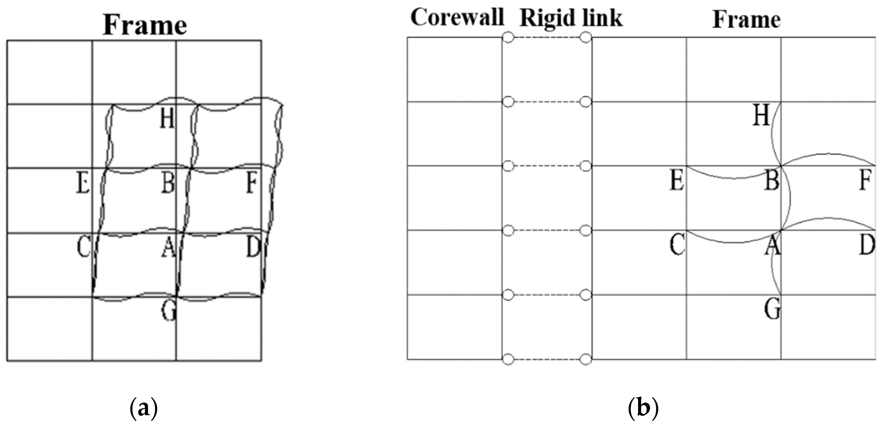
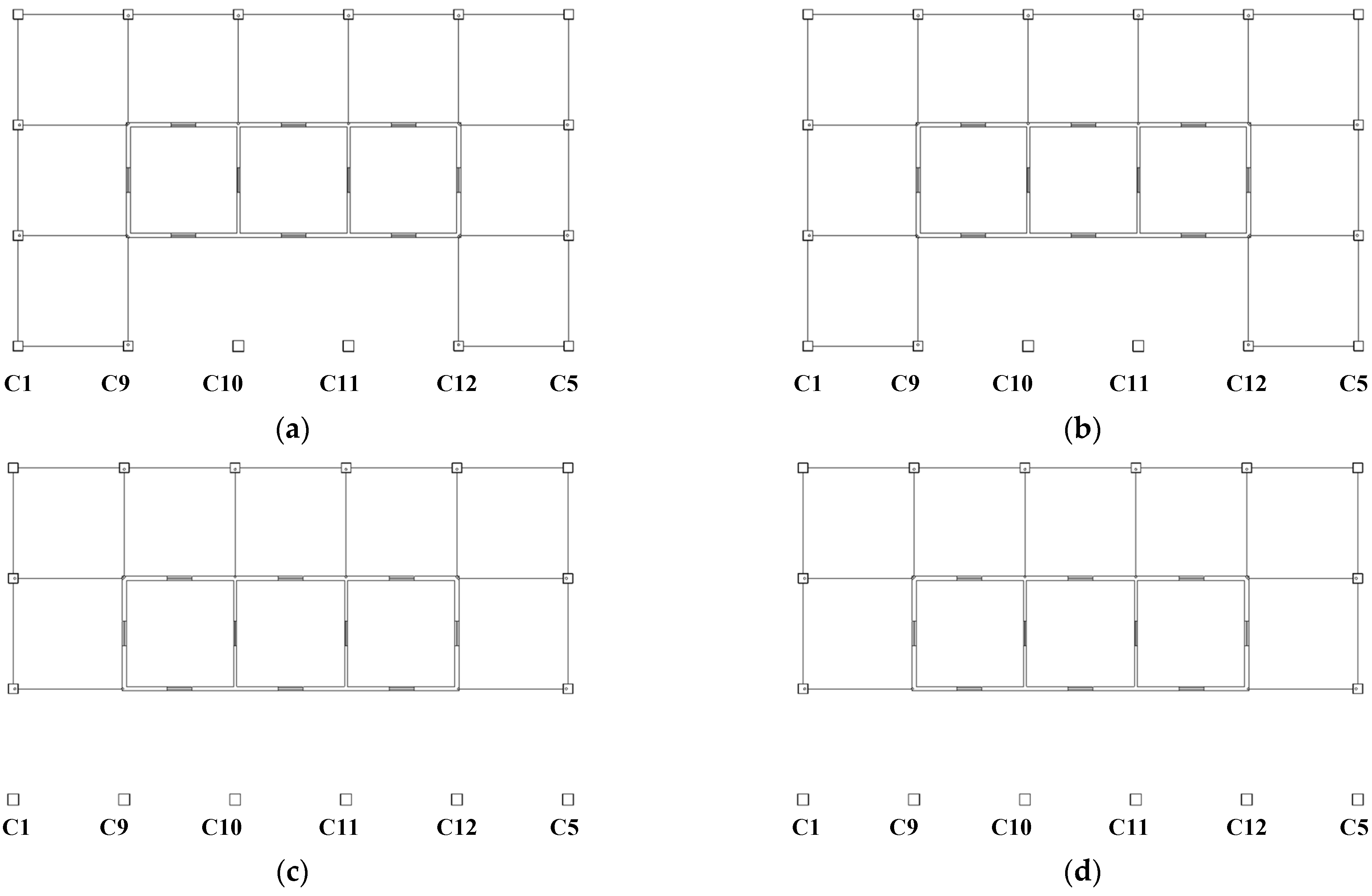
In modern buildings, such as commercial, office, and hotel buildings, the beams and columns of the frame are partially reduced due to the layout needs of the large local space at the bottom of the building, and columns are formed of more than two stories in height, or so-called slender columns. Cross-layer columns can be combined with the frame, frame–shear wall, and frame–core wall structures, which are widely used in engineering. Since the frame–core wall structure is the most common form of high-rise and super high-rise hybrid structure, the frame–core wall structure with cross-layer columns has great research value. For the building with cross-layer columns in the frame–core wall structure, as shown in Figure 1, the structure can be divided into the cross-layer column part and the remaining frames’ sub-structure part.
There are many studies on the load-bearing performance and stability performance of cross-layer column members [18,19,20]. Since the load-carrying capacity of slender columns is affected by the effective length, Ma et al. [21] proposed a new method to calculate the effective length of the column based on the equivalent model and used the finite element for eigenvalue buckling analysis. However, most of the studies have mainly focused on the member level, and fewer studies have been conducted at the structural level.
The frame–core wall structure is a double-layer lateral force-resisting system; the core shear wall is usually the main lateral force-resisting structure in engineering, and the frame is used as the second line of defense for structural seismic resistance. For the structural columns in the double lateral force resisting system, due to the support of the shear wall or core, the effective length factor is often between the laterally shifted frame with hinged ends and the non-lateral shifted frame with rigid ends. If the calculation is performed exactly according to the frame with lateral shift, it will lead to too conservative calculation results, which will increase the cost of design and cause unnecessary waste; if the calculation is performed exactly according to the frame without lateral shift, it will lead to the settlement result on the side of being an unsafe and unreasonable design. The lateral stiffness of the frame–core barrel structure with cross-layer columns is abruptly changed, and the force mechanism is somewhat different from that of the ordinary frame–core barrel structure, so the Technical Points for Special Review of Seismic Protection of Super-limited High-rise Building Projects in China [22] classifies the cross-layer column as a local irregularity.
In order to investigate the effective length factors of the frame–core wall structure with cross-layer columns, this study compared the results of GB 50017-2017 with those obtained through ABAQUS using the D-value method. The study quantitatively investigated the effects of the height and distribution of cross-layer columns on the lateral stiffness ratio, natural vibration period, internal forces of members, maximum inter-story displacement, and effective length of the structure. Based on the findings, a modified method for the effective length factor that aligns with the real results was proposed.

2. Effective Length Modification for Frame–Core Wall Structures with Cross-Layer Columns

2.1. D-Value Method for Lateral Stiffness

The improved inflection point method (D-value method) can be used to determine the flexural stiffness of columns before yielding occurs in structural beams, and thus to analyze the lateral stiffness of the substructure. The lateral stiffness of the frame column can be calculated as follows:
D i j = α 12 i c h 2
i c = E I c h
α = 0.5   +   i ¯ 2   +   i ¯   ( Bottom ) i ¯ 2   +   i ¯   ( Other   layers )
where ic is the column linear stiffness; h is the column length; α is the column lateral stiffness coefficient.
In Equation (3), i ¯ is the beam–column line stiffness ratio. When the frame columns and beams on the same floor have the same specification, the beam–column line stiffness ratio of the middle column is twice that of the side column. This is because both sides of the middle beam are restrained by the floor slab. On the other hand, the column at the top floor of the substructure adjacent to the column through the floor is missing one side of the beam at its lower end. As a result, the beam–column line stiffness ratio is 1.5 times the side column.
The lateral stiffness of the frame in-plane is defined by Equation (4).
S F = D i j × h

2.2. Effective Length Factor in GB 50017-2017

GB 50017-2017 Steel Structure Design Standard provides the effective length factor of frame column with lateral shift, which is given by Equation (5).
μ i = 7.5 K 1 K 2   +   4 ( K 1   +   K 2 )   +   1.52 7.5 K 1 K 2   +   K 1   +   K 2
where K1 and K2 are the ratio of the sum of the beam line stiffness and the sum of the column line stiffness intersecting the upper and lower ends of the column, respectively.
The buckling load Pcr of the columns can be obtained from Euler’s formula, as shown in Equation (6), where m denotes the number of short-sided frame columns; ith denotes the i-th layer; EIcj is the flexural stiffness of the column; μi denotes the effective length factor of the j-th column in the i-th layer obtained according to the GB 50017-2017.
P c r = j = 1 m π 2 E I c j μ j h i 2
The effective length factor method in GB50017-2017 considers the restraint strength of the upper and lower end of the column and this method is suitable for plane frames. For the frame–core structure, the side columns experience strong restraint from the frame beams within the frame plane. Outside the frame plane, the side columns are often connected to the core via the floor beams with small cross-sectional dimensions. Since the floor beams are usually hinged with the columns, the side columns are subjected to little out-of-plane restraint. The application of the effective length factor method is challenging since it predicts that the stable bearing capacity of out-of-plane frame columns is nearly zero, which does not align with the actual situation.
The location of cross-layer columns in the structural layout can cause an abruptly change in the lateral stiffness resistance of the floor. In GB 50017-2017, the lateral stiffness of a structure is determined based on the surrounding restraint of individual members, and it does not consider the torsional effect produced by vertical irregular structures, as shown in Figure 2. Furthermore, this design standard only considers weak direction members in the overall lateral stiffness of the structure, and does not include the influence of the interaction between multiple members. Additionally, different distribution forms of the cross-layer columns are also not considered.

2.3. Modification of Effective Length Factor

The frame column linear stiffness was obtained using the D-value method, and the effective length factor of the frame column was then obtained using GB 50017-2017, so as to derive the ultimate bearing capacity of the column using the Euler formula. This method only considers the column end constraints, and ignores the distribution and interaction of frame columns; in particular, for the frame–core wall structure with cross-layer columns, it ignores the sudden change in lateral stiffness caused by the cross-layer column and the supporting effect of the core. Therefore, this calculation method has a large deviation from the actual engineering results.
For the frame–core wall structure with cross-layer columns, firstly, the ultimate bearing capacity PF,cr of the single floor can be calculated according to GB 50017-2017. Combined with the finite element calculation results, the percentage of vertical load on a single cross-layer column in the vertical load on all columns of this floor can be obtained. Then, Equation (7) is used to obtain the modified ultimate bearing capacity PF,cri of a single cross-layer column on the basis of GB 50017-2017. RFW, RF are the design values of gravity loads at the bottom of the frame–shear wall and frame, respectively.
P F , cri = N i i = 1 n N i R FW R F P F , cr = N i i = 1 n N i P F , cr
The corrected effective length factor μ′ of the cross-layer column is inverted by Euler’s formula, shown in Equation (8).
μ = π 2 E I i h 2 P F , cri = π 2 E I i h 2 P F , cr i = 1 n N i N i

2.4. Buckling Load for Frame–Core Wall Structure

It is assumed that the overall buckling load of the frame–core structure, which consists of the sum of the buckling loads of both the frame part and the shear wall part, can be expressed by Equation (9).
P FW , cr = P F , cr   +   P W , cr = S F   +   3 π 2 E W I W 4 H 2
where SF is the lateral stiffness of the frame; its value is equal to the buckling load of the frame PF,cr. PW,cr is the buckling load of shear walls, as the shear walls under lateral load to bending deformation can be regarded as cantilever vertical members, and their buckling load can be calculated by the Euler formula approximation. EWIW is the equivalent lateral stiffness of the shear walls.
The parameter γ is introduced as the buckling load correction factor for the frame section, as shown in Equations (10) and (11).
γ = R F R F W P F W , c r P F , c r = ρ ( 4 λ 2   +   3 π 2 ) 4 λ 2
ρ = R F R F W
where the parameter γ is the frame buckling load correction factor. ρ is the design value of the gravity load at the bottom of the frame as a proportion of the overall structure of the structure.
The modified buckling load of frame column j at floor i is shown in Equation (12).
P ij , cr = N i j j = 1 n N i j γ P F , cr
As can be seen from Equation (10), the frame buckling load correction factor γ can be used to quantitatively characterize the extent to which the frame is subjected to the strength of the lateral support of the core barrel; when γ > 1, it indicates that the frame is helped by the core barrel stiffness, and its buckling load is higher than that of the frame with the lateral shift; when γ = 1, it indicates that the buckling factor of the frame is the same as that of the core barrel, and the buckling load of the frame is the buckling load of the frame with the lateral shift; when γ < 1, it indicates that the stability of the core barrel needs the help of the frame part, so the flexural load of the frame is lower than the flexural load of the frame with the lateral shift.
The variation in the frame buckling load correction factor γ with the stiffness characteristic value λ is shown in Figure 3. It can be seen from the figure that as λ increases, the buckling load correction factor γ of the frame decreases; when the vertical load shared by the frame is larger, the buckling load correction factor γ also increases. For most of the dual lateral force resisting systems, the frame buckling load correction factor γ is greater than 1.0, and its buckling load is between the frame with the lateral shift and the frame without the lateral shift.

3. FE model Setting

3.1. Ordinary Frame–Core Wall Structure Model

The calculation example of this study adopts a frame–core wall structural system, and the structural plan size is 45 m × 27 m. The spacing of frame columns is 9 m, and concrete-filled steel tube members are utilized. The frame beams are H-shaped steel beams. The plane size of the core wall in the center of the structure is 27 m × 9 m, and the width of the hole is 2.0 m. The overall height of structure H is 120 m, with 28 floors. The height of the 1st~3rd floors is 5 m, while the height of the rest of the floors is 4.20 m. The layout of the frame–core structure is shown in Figure 4.
To investigate the influence of the number of cross-stories on the effective length factor, four models were built on the basis of the original model. In Model 1 and Model 3, the 1st to 2nd floors are the cross-story area. In Model 2 and Model 4, the 1st to 3rd floors are the cross-story area. Model 1 and Model 2 are cross-story columns between columns C9 and C12. Model 3 and Model 4 are the cross-layer columns between columns C1 and C5. The first-floor structural arrangement of these four frame–core wall structures is shown in Figure 5.
To ensure the accuracy of the analysis results, the cross-sectional specifications of members were gradually adjusted based on the rationality of the structural design, the requirements of the design conditions, and code standards. The minimum thickness of the shear wall is 250 mm, the height of all connecting beams is 1000 mm, and the concrete strength grade is C40~C60. The minimum cross-sectional size of concrete-filled steel tubular column is □700 × 20 mm, the steel material used is Q355B, and the concrete strength grade is C40~C50. The minimum cross-sectional size of the H-shaped section steel frame beam is H650 × 300 × 18 × 25 mm, and the steel material is Q355B. The variation in shear wall thickness, cross-section size of members, steel thickness, and material strength grade with structural height are shown in Table 1. The thickness of the floor slab is 120 mm and the strength grade of concrete is C30.
The minimum thickness of the shear wall is 250 mm, the height of all connecting beams is 1000 mm, and the concrete strength grade is C40~C60. The minimum cross-sectional size of concrete-filled steel tubular column is □700 × 20 mm, the steel material used is Q355B, and the concrete strength grade is C40~C50. The minimum cross-sectional size of the H-shaped section steel frame beam is H650 × 300 × 18 × 25 mm, and the steel material is Q355B. The variation in shear wall thickness, cross-section size of members, steel thickness, and material strength grade with structural height are shown in Table 1. The thickness of the floor slab is 120 mm and the strength grade of concrete is C30.
The finite element model was established in ABAQUS, in which the frame beam and column are simulated by B31 beam elements, the shear walls are simulated by S4R elements, and the floors are rigid slabs [23]. The mesh size of the beam, column, and wall elements is about 1000 mm, and the continued reduction in the mesh size has little effect on the results but the computation time increases significantly. The fixed support is simulated by constraining 3 translational degrees of freedom and 3 rotational degrees of freedom at the bottom of the columns. ABAQUS software-based linear elastic buckling BUCLK analysis was undertaken of the working conditions. The steel constitutive model is an ideal elastic-plastic model, and the Concrete Damaged Plasticity (CDP) constitutive model is used for concrete. The modulus of elasticity of the steel is 206,000 MPa and Poisson’s ratio is 0.3.

3.2. Main Calculation Parameters

The self-weight of structural members was calculated based on the cross-sectional dimensions of members and material unit weight (concrete unit weight is 25 kN/m3, steel unit weight is 78.5 kN/m3). Additionally, the floor has a dead load of D = 5 kN/m2, which includes the weight of the curtain wall. The live load on the floor L = 2.5 kN/m2. In the ultimate stability bearing capacity analysis, the corresponding load combination condition is 1.3 × D + 1.5 × L.
In JGJ 3-2010 Technical Regulations for Concrete Structures of High-rise Buildings [24], the seismic level of shear walls and frames is determined according to the height of the structure and the fortification intensity, and its axial pressure ratio limit value is shown in Table 2. The seismic intensity is 7 degrees, the peak seismic acceleration is 0.10 g, the design seismic grouping is group I, and the characteristic period Tg of the site is 0.45 s. The basic wind pressure for the 50-year recurrence period is 0.50 kN/m2, and the ground roughness category is group C.
In the finite element analysis model, it was assumed that the in-plane stiffness of the floor slab is infinite and the out-of-plane stiffness is zero. The frame columns were connected to the core through the floor beams, which were hinged at both ends. The stiffness amplification factor of the H-beam composite frame beam is 1.5. Furthermore, the inter-story displacement angle of the structure is no more than 1/800 under the action of the multi-stress earthquake and wind load.

4. Structural Performance of Frame–Core Wall Structures with Cross-Layer Columns

4.1. Dynamic Characteristics

4.1.1. Period and Vibration Pattern

ABAQUS was utilized to model the frame and core wall structure with cross-layer columns. Table 3 presents the natural periods and vibration modes. All four calculation models meet the requirement that the ratio of the first natural period, which is dominated by torsion, to the first natural period, which is dominated by advection, should not be more than 0.9 according to JGJ3-2010 [24]. Additionally, the first vibration mode of the four models was translations in the Y-direction, the second vibration mode was translations in the X-direction, and the third vibration mode was twisting in the Z-direction.

4.1.2. Maximum Inter-Story Displacement Angle

To obtain the maximum inter-story displacement angle, earthquake load and wind load were applied separately to the structures. The stiffness of the structure in the Y-direction is small, but all calculations meet the requirement of 1/800. The ratio of the maximum inter-story displacement angle to the average displacement angle of the vertical members of the floor is less than 1.5 under the specified horizontal earthquake action, considering the effect of accidental eccentricity. The cross-layer column makes the structure produce a weak layer, and it is known from Table 4 that the maximum inter-story displacement angle of the structure increases with the number and height of the cross-layer columns.

4.1.3. Shear-to-Weight Ratio

Table 5 shows the shear-to-weight ratio at the bottom of the frame–core wall structure under seismic action. The stiffness of the structure in the Y-direction is small, and all meet the requirements of the GB50011-2010 Code for Seismic Design of Buildings [25] for a minimum shear-to-weight ratio of not less than 0.016. The shear-to-weight ratio is not significantly affected by changes in the height and number of columns through the floor.

4.1.4. Rigidity-to-Weight Ratio

In the actual project, to ensure the lateral stiffness of the structure, the cross-sectional size of the selected column increases with the height of the cross-layer column. As shown in Table 6, the structural stiffness-to-weight ratio increases with the increase in the number of cross-layer columns due to the increase in column cross-sectional size, but it decreases with the increase in the height of cross-layer columns.

4.1.5. Base Reaction Force

The vertical reaction forces at the bottom of the frame and core wall are shown in Table 7 in the gravity load design condition. Table 7 shows that the frame vertical reaction force accounts for about 45% and the core wall vertical reaction force accounts for about 55%.

5. Stability Analysis of Frame–Core Wall Structure with Cross-Layer Columns

ABAQUS was used to analyze the buckling mode of the frame–core wall structures with the cross-layer columns when the overall instability occurs, and to obtain the buckling load capacity and buckling factor at the overall level of the structure.

5.1. Buckling Mode Analysis

The buckling mode of the frame–core structure with different numbers and heights of cross-layer columns when the intensity of protection is 7 degrees is shown in Figure 6. From the figure, the form of instability of the model is bending-shear instability, which is the same as that of the ordinary frame–core structure. The deformation is mainly concentrated in the middle and upper parts of the structure, and the deformation in the lower part is smaller.

5.2. Buckling Load and Coefficient

The buckling bearing capacity and buckling coefficient of the frame–core wall with cross-layer columns in the first-order buckling mode when the overall instability occurs is shown in Table 8. The overall buckling capacity of the structure decreases with the increase in the number of cross-layer columns and the number of stories. The buckling coefficient increases with the increase in the number of cross-layer columns and the decrease in the number of stories.

5.3. Effective Length Factor for Cross-Layer Columns

The effective lengths and stable bearing capacities of the cross-layer columns in the frame–core wall structure are shown in Table 9, Table 10, Table 11 and Table 12. As can be seen from the tables, the effective length coefficient calculation method of the cross-layer columns is modified by considering the interaction between the substructure and the cross-layer columns, and the calculation results of this method are closer to those calculated by the finite element method.

6. Conclusions

(1)
The lateral stiffness ratio of the structure decreases, and the maximum inter-story displacement angle and natural vibration period increase, as the height and number of cross-layer columns increase.
(2)
The overall buckling load of the structure decreases with the increase in the number of cross-layer columns and the number of stories. The buckling coefficient increases with the increase in the number of cross-layer columns and the decrease in the number of stories. The remaining beams and columns of the structure with cross-layer columns can be regarded as sub-structures, and their lateral stiffness can be calculated according to the ordinary frame structure, thus simplifying the calculation model.
(3)
GB 50017-2017 only considers the force of the frame in the weak axis direction and does not include the influence of the core wall on the distribution of bearing capacity, which is somewhat different from the actual force mechanism. Therefore, this study proposes a new modification method for determining the effective length factor of the cross-layer columns, which considers the interaction between the substructure and the cross-layer columns, as well as the core wall on the frame. The modified effective length factor of the cross-layer columns is more consistent with the actual force situation.
(4)
In this study, a typical frame–core wall structure of 140 m was selected for analysis with a constant superstructure height, and it is assumed in the simplified model that the frame is connected to the core wall by rigid links hinged at both ends. Therefore, the applicability of the modified formula proposed in this study for different axial compression ratios and the effect of frame-to-core wall interaction need to be further investigated.

Author Contributions

Conceptualization, Z.M. and Z.F.; methodology, Y.X.; software, Y.X.; validation, Z.F. and Y.X.; formal analysis, Y.X.; investigation, Y.X. and Y.Y.; resources, Z.F.; data curation, Y.X.; writing—original draft preparation, Y.X.; writing—review and editing, Y.Y. and Y.X.; visualization, Y.X. and Y.Y.; supervision, Z.M. All authors have read and agreed to the published version of the manuscript.

Funding

This research was funded by the National Natural Science Foundation of China grant number 51578064 and the Natural Science Foundation of Beijing Municipality grant number 8172031.

Data Availability Statement

All the data supporting the results were provided within the article.

Conflicts of Interest

The authors declare no conflict of interest.

References

  1. Webber, A.; Orr, J.; Shepherd, P.; Crothers, K. The effective length of columns in multi-storey frames. Eng. Struct. 2015, 102, 132–143. [Google Scholar] [CrossRef] [Green Version]
  2. Chen, W.F.; Kim, S.E. LRFD Steel Design Using Advanced Analysis; CRC Press: New York, NY, USA, 1997. [Google Scholar]
  3. Task Committee on Effective Length of Technical Committee on Load and Resistance Factor Design of ASCE. Effective Length and Notional Load Approaches for Assessing Frame Stability: Implications for American Steel Design; ASCE Publications: Reston, VA, USA, 1997. [Google Scholar]
  4. Tong, G.S.; Wang, J.P. Column effective length considering inter-story and inter-column interactions in sway-permitted frames. J. Constr. Steel Res. 2006, 62, 413–423. [Google Scholar] [CrossRef]
  5. Uribe-Henao, A.F.; Zapata-Medina, D.G.; Arboleda-Monsalve, L.G.; Aristizabal-Ochoa, J.D. Static and Dynamic Stability of a Multi-stepped Timoshenko Column Including Self-weight. Structures 2018, 15, 28–42. [Google Scholar] [CrossRef]
  6. Ma, T.; Xu, L. Storey-based stability of unbraced steel frames under piece-linear temperature distributions. Eng. Struct. 2019, 194, 147–160. [Google Scholar] [CrossRef]
  7. Mansour, W.; ATayeh, B.; Tam, L. Finite element analysis of shear performance of UHPFRC-encased steel composite beams: Parametric study. Eng. Struct. 2022, 271, 114940. [Google Scholar] [CrossRef]
  8. GB50017-2017; Standard for Design of Steel Structures. Architecture & Building Press: Beijing, China, 2017.
  9. ANSI/AISC 360-16; Specification for Structural Steel Buildings. American Institute of Steel Construction: Chicago, IL, USA, 2016.
  10. de Construção, A.P. Eurocode 3 Part:1-1 Design of Steel Structures: General Rules and Rules for Buildings; European Committee for Standardization: Brussels, Belgium, 2005. [Google Scholar]
  11. Kishi, N.; Chen, W.F. Moment-Rotation Relations of Semi-Rigid Connections with Angles. J. Struct. Eng. 1990, 116, 1813–1833. [Google Scholar] [CrossRef]
  12. Ziemian, R.D. Guide to Stability Design Criteria for Metal Structures, 6th ed.; Wiley: New York, NY, USA, 2010. [Google Scholar]
  13. Aristizabal-Ochoa, J.D. Story stability of braced, partially braced and unbraced frames: Classical approach. J. Struct. Eng. 1997, 123, 799–807. [Google Scholar] [CrossRef]
  14. Aristizabal-Ochoa, J.D. Large Deflection Stability of Slender Beam-Columns with Semi-Rigid Connections: Elastica Approach; ASCE: Reston, VA, USA, 2004; Volume 130, pp. 274–282. [Google Scholar]
  15. Farajian, M.; Sharafi, P.; Kildashti, K. The influence of inter-module connections on the effective length of columns in multi-story modular steel frames. J. Constr. Steel Res. 2021, 177, 106450. [Google Scholar] [CrossRef]
  16. Tian, W.F.; Sun, J.L.; Hao, J.P. Effective length factors of three- and two-segment stepped columns. J. Constr. Steel Res. 2021, 181, 106585. [Google Scholar] [CrossRef]
  17. Tian, W.F.; Hao, J.P.; Zhong, W.H. Buckling of stepped columns considering the interaction effect among columns. J. Constr. Steel Res. 2021, 177, 106416. [Google Scholar] [CrossRef]
  18. Li, X.; Wang, X.; Liu, J.; Chen, Y.F. Behavior and design of eccentrically-loaded slender tubed steel-reinforced high-strength concrete columns. J. Constr. Steel Res. 2023, 205, 107907. [Google Scholar] [CrossRef]
  19. Ci, J.; Ahmed, M.; Liang, Q.Q.; Chen, S.; Chen, W.; Sennah, K.; Hamoda, A. Experimental and numerical investigations into the behavior of circular concrete-filled double steel tubular slender columns. Eng. Struct. 2022, 267, 114644. [Google Scholar] [CrossRef]
  20. Yang, Y.F.; Fu, F.; Bie, X.M. Behaviour of rectangular RACFST slender columns under eccentric compression. J. Build. Eng. 2021, 38, 102236. [Google Scholar] [CrossRef]
  21. Ma, H.W.; Ye, L.; Lin, L. A study on effective length of slender column with elastic restraints. Procedia Eng. 2017, 210, 228–234. [Google Scholar] [CrossRef]
  22. Ministry of Housing and Urban-Rural Development of the People’s Republic of China. Technical Points for Special Review of Seismic Protection of Super High-Rise Building Projects: Building Quality No. 67; Ministry of Housing and Urban-Rural Development of the People’s Republic of China: Beijing, China, 2015. [Google Scholar]
  23. ABAQUS Inc. Analysis User’s Manual I_V; Version 6.11; ABAQUS: Palo Alto, CA, USA; Dassault Systemes: Vélizy-Villacoublay, France, 2011. [Google Scholar]
  24. JGJ 3-2010; Technical Regulations for Concrete Structures of High-Rise Buildings. Architecture & Building Press: Beijing, China, 2010.
  25. GB50011-2010; Code for Seismic Design of Buildings. Architecture & Building Press: Beijing, China, 2010.
Figure 1. Frame–core wall structure with cross-layer column.
Applsci 13 06875 g001
Figure 2. Column effective length factor study ‘seven-rod model’. (a) Analytical model with lateral shift frame; (b) lateral shift-free frame analysis model.
Applsci 13 06875 g002
Figure 3. Variation in frame buckling load correction factor γ with stiffness eigenvalue λ.
Applsci 13 06875 g003
Figure 4. Ordinary frame–core wall structure. (a) Three-dimensional schematic of frame–core wall structure; (b) first floor plan of frame–core wall structure/mm.
Applsci 13 06875 g004
Figure 5. Floor plan of the first floor. (a) Model 1; (b) Model 2; (c) Model 3; (d) Model 4.
Applsci 13 06875 g005
Figure 6. Buckling mode of the frame–core wall. (a) Model 1; (b) Model 2; (c) Model 3; (d) Model 4.
Applsci 13 06875 g006
Table 1. Calculation model component specifications.
ModelsFloor
Range
Component Type
Outer Shear Wall/mmInner Shear Wall/mmFrame Column/mmFrame Beam/mm
Model 122–28250 (C40)180 (C40)□700 × 20 (C40)H650 × 300 × 18 × 25
15–21300 (C40)200 (C40)□750 × 20 (C40)H700 × 300 × 18 × 25
8–14300 (C45)200 (C45)□750 × 22 (C45)H700 × 300 × 20 × 30
1–7350 (C50)250 (C50)□800 × 22 (C50)H750 × 300 × 20 × 30
1–2 Cross-layer area350 (C50)250 (C50)□900 × 25 (C50)H800 × 350 × 22 × 30
Model 222–28250 (C40)180 (C40)□700 × 20 (C40)H650 × 300 × 18 × 25
15–21300 (C40)200 (C40)□750 × 20 (C40)H700 × 300 × 18 × 25
8–14300 (C45)200 (C45)□750 × 22 (C45)H700 × 300 × 20 × 30
1–7350 (C50)250 (C50)□800 × 22 (C50)H750 × 300 × 20 × 30
1–3 Cross-layer area350 (C50)250 (C50)□1000 × 28 (C50)H900 × 350 × 24 × 35
Model 322–28250 (C40)180 (C40)□700 × 20 (C40)H650 × 300 × 18 × 25
15–21300 (C40)200 (C40)□750 × 20 (C40)H700 × 300 × 18 × 25
8–14300 (C45)200 (C45)□750 × 22 (C45)H700 × 300 × 20 × 30
1–7350 (C50)250 (C50)□800 × 22 (C50)H750 × 300 × 20 × 30
1–2 Cross-layer area350 (C50)250 (C50)□900 × 25 (C50)H800 × 350 × 22 × 30
Model 422–28250 (C40)180 (C40)□700 × 20 (C40)H650 × 300 × 18 × 25
15–21300 (C40)200 (C40)□750 × 20 (C40)H700 × 300 × 18 × 25
8–14300 (C45)200 (C45)□750 × 22 (C45)H700 × 300 × 20 × 30
1–7350 (C50)250 (C50)□800 × 22 (C50)H750 × 300 × 20 × 30
1–3 Cross-story area350 (C50)250 (C50)□1000 × 28 (C50)H900 × 350 × 24 × 35
Table 2. Seismic rating of hybrid frame–shear wall structures.
Shear WallFrame
Seismic RatingAxial Pressure RatioSeismic RatingAxial Pressure Ratio
20.620.8
Table 3. Natural period of frame–core wall structures.
Order of VibrationModel 1Model 2Model 3Model 4Description of Vibration Type
T1/s4.21274.25124.21194.2486Horizontal mode along Y direction
T2/s2.14112.15642.14102.1561Horizontal mode along X direction
T3/s1.99531.98391.99471.9823Twisting mode along Z-direction
Tt/T10.47360.46670.47360.4666
Table 4. Maximum inter-story displacement angle of frame–core wall structures.
RoleDirectionModel 1Model 2Model 3Model 4
EarthquakeX-direction1/26051/25931/26061/2594
Y-direction1/8631/8551/8631/856
Wind loadX-direction1/57701/56731/57701/5674
Y-direction1/8851/8701/8851/856
Table 5. Shear-to-weight ratio at the bottom of the frame–core wall structures/percent.
Seismic DirectionModel 1Model 2Model 3Model 4
X-direction1.6000 (1.60)1.6000 (1.60)1.6000 (1.60)1.6000 (1.60)
Y-direction1.4400 (1.45)1.4300 (1.45)1.4400 (1.45)1.4300 (1.45)
Note: The minimum shear-to-weight ratio required by GB5011-2010 is shown in parentheses.
Table 6. Stiffness-to-weight ratio of frame–core wall structures.
RoleDirectionModel 1Model 2Model 3Model 4
EarthquakeX-direction9.03909.02409.06309.0590
Y-direction2.25202.23202.25802.2410
Wind loadX-direction7.66307.67407.69107.7270
Y-direction2.01202.00902.02002.0250
Table 7. Reaction forces at the bottom of frame and core shear wall.
ModelRFW/NRF/NRF/RFWRW/NRW/RFW
16.1728 × 1082.7850 × 1080.45123.3878 × 1080.5488
26.1514 × 1082.7734 × 1080.45083.3781 × 1080.5492
36.1516 × 1082.7695 × 1080.45023.3821 × 1080.5498
46.1123 × 1082.7457 × 1080.44923.3666 × 1080.5508
Note: RFW, RF, and RW are representative values of gravity loads borne at the bottom of the frame–core wall structure, frame columns, and core shear wall, respectively.
Table 8. Buckling bearing capacity and buckling coefficient.
Model 1Model 2Model 3Model 4
Pcr/kN7.0474 × 1096.9283 × 1097.0251 × 1096.8910 × 109
λ11.417011.263011.420011.2740
Table 9. Effective length factor in Model 1.
Column NumberFinite Element MethodGB50017 Method
Vertical Force kNμBefore Modification μAfter Modification μ
C101.9018 × 1071.2618/1.3408
C111.9018 × 1071.2618/1.3408
Table 10. Effective length factor in Model 2.
Column NumberFinite Element MethodGB50017 Method
Vertical Force kNμBefore Modification μAfter Modification μ
C101.8740 × 1071.0555/1.0248
C111.8740 × 1071.0555/1.0248
Table 11. Effective length factor in Model 3.
Column NumberFinite Element MethodGB50017 Method
Vertical Force kNμBefore Modification μAfter Modification μ
C11.2714 × 1071.54301.76121.8320
C91.8367 × 1071.2838/1.5242
C101.8919 × 1071.2649/1.5018
C111.8919 × 1071.2649/1.5018
C121.8367 × 1071.2838/1.5242
C51.2714 × 1071.54301.76121.8320
Table 12. Effective length factor in Model 4.
Column NumberFinite Element MethodGB50017 Method
Vertical Force kNμBefore Modification μAfter Modification μ
C11.2625 × 1071.28531.67751.4239
C91.7981 × 1071.0770/1.1931
C101.8500 × 1071.0618/1.1763
C111.8500 × 1071.0618/1.1763
C121.7981 × 1071.0770/1.1931
C51.2625 × 1071.28531.67751.4239
Disclaimer/Publisher’s Note: The statements, opinions and data contained in all publications are solely those of the individual author(s) and contributor(s) and not of MDPI and/or the editor(s). MDPI and/or the editor(s) disclaim responsibility for any injury to people or property resulting from any ideas, methods, instructions or products referred to in the content.

