Abstract
The diaphragm is a key component of the lithium-ion battery and largely determines its performance. Currently, commercial diaphragms suffer from poor thermal stability, low porosity, and low liquid absorption rate. In this study, we prepared a polyurethane/polyacrylonitrile (PU/PAN) lithium-ion battery diaphragm using a centrifugal spinning method with PU as the main substrate and PAN as the additive. The results showed that the PU/PAN nanofiber diaphragm prepared by centrifugal spinning had a 3D porous structure, and when using 18% PU:PAN = 7:3, the porosity of the fiber diaphragm was 83.9%, the liquid absorption rate was 493%, and the ionic conductivity was 1.79 mS/cm. The battery system had good electrochemical performance and thermal stability, with an electrochemical stability window of 5.2 V. The diaphragm did not shrink when heated at 160 °C. In a lithium-ion battery system with lithium iron phosphate (LiFePO4) as the cathode material, the capacity remained at 147.1 mAh/g after 50 cycles at a 0.2 C rate, with a capacity retention rate of 95.8%. This indicated excellent cycle stability and a multiplicative performance with good application potential.
1. Introduction
Despite rapid scientific and technological development, the world is facing an increasing demand for energy and the need to control the resulting environmental pollution, which makes the development of new green industries an urgent priority. Lithium-ion batteries are commonly used in many fields, such as electronic devices and the aerospace industry, because of their many advantages, such as high energy density, low power consumption, recyclability, and low carbon emissions. The diaphragm is a key component of the lithium-ion battery and largely determines its performance [1,2,3]. The film properties of lithium-ion batteries determine the capacity, cycling stability, and other important battery characteristics, and therefore the diaphragm must have an adequate thickness, ionic conductivity, high porosity, and both thermal and electrochemical stability [4,5,6].
Currently, commercial diaphragms are microporous membranes based on polypropylene (PP), polyethylene (PE), and their composites. These diaphragms have low porosity and liquid absorption rates and poor thermal stability due to the hydrophobic properties of the constituent materials. This makes the electrochemical performance of lithium-ion battery diaphragms poor, and commercial diaphragms are susceptible to shrinkage when heated, which is not conducive to maintaining the long-term stable operation of lithium-ion batteries, especially after repeated charging and discharging; the diaphragm is heated, which can easily cause a short circuit inside the battery. Additionally, their cumbersome preparation process, difficult equipment control, and high-cost limit their application in electric vehicles and energy storage systems. These problems can be solved by using different types of polymer diaphragms and by using different diaphragm manufacturing techniques [7,8]. To replace the traditional polyolefin microporous membrane, high-performance lithium-ion battery diaphragms have been prepared at the laboratory scale using dry and wet spinning, electrostatic spinning, and centrifugal spinning methods. Zhang D. et al. [9] prepared polypropylene/polyethylene (PP/PE) composite diaphragms with a shut-off function by dry biaxial stretching. When the temperature rises to 135 °C, the PE inside the diaphragm melts, blocking the channels for lithium-ion transport. Dahe et al. [10] used a wet spinning process to prepare a polysulfone/polyvinylpyrrolidone fiber diaphragm. However, the wide range of pore sizes of the polyolefin microporous diaphragm prepared by the wet and dry spinning method resulted in a localized diaphragm with a resistance that was too high. Unlike the dry-wet method, the fiber diaphragms prepared by this method usually have high porosity, liquid absorption, and thermal stability due to the specificity of the electrostatic spinning process.
Li et al. [11] prepared polyacrylonitrile/polyimide (PAN/PI) composite films by electrostatic spinning, and their composite films had good thermal stability and exhibited better mechanical properties than the original PAN films. Khan et al. [12] improved the wettability and ionic conductivity of the diaphragm by the electrostatic spinning of polyacrylonitrile (PAN) and polymethyl methacrylate (PMMA) to produce lithium-ion battery diaphragms with embedded graphene nanoflakes. Cheng et al. [13] successfully modified 3D nanofiber-structured polyurethane (PU) into a novel PU-coated diaphragm using an electrostatic spinning process. Its fiber morphology was better, and its average pore size was lower than that of commercial PP diaphragms, but its porosity (63.7%), liquid absorption(371%), and ionic conductivity were greatly improved compared with commercial diaphragms, and it had a lower interfacial resistance and good multiplicative properties.
The electrostatic spinning method is not efficient enough for mass production, while the fibers spun by centrifugal spinning have good orientation, a uniform diameter distribution, and the advantages of no voltage, a high yield, a simple structure, no pollution, and low production costs [14,15]; therefore, providing a good alternative to electrostatic spinning. Yanilmaz et al. [16] prepared polymethyl methacrylate/polyacrylonitrile (PMMA/PAN) films with different blending ratios by centrifugal spinning, which possessed a high porosity and wicking rate. For PMMA/PAN (50/50) membranes, the porosity and wicking rate are 73% and 370%, respectively. Lv et al. [17] prepared poly(vinylidene fluoride) (PVDF)/polyacrylonitrile (PAN) blended nanofiber diaphragms by centrifugal spinning, and the cells possessed excellent cycling stability and multiplicative performance, but their diaphragms still had problems, such as poor electrochemical stability, and therefore the preparation of lithium-ion battery diaphragms by a centrifugal spinning method still needs to be improved.
The development of high-performance composite diaphragms for lithium-ion batteries is being actively studied. Xie et al. [18] prepared oxide aluminum-coated films by a physicochemical wet dipping method using aluminum oxide nanoparticles with a poly(vinylidene fluoride-hexafluoropropylene) trilayer polymer. The electrolyte affinity of the diaphragm, the absorption rate, and the thermal dimensional stability of the diaphragm were significantly improved. Cho et al. [19] coated both sides of a PE diaphragm with aminated silica particles by immersion to give a higher ionic conductivity with better wettability and cycling stability than the conventional PE diaphragm. Yang Y et al. [20] used the non-solvent induced phase separation (NIPS) technique to prepare polyvinylidene fluoride (PVDF)/vermiculite nanosheet (VNs) lithium battery (LIB) diaphragms. When the VNs content reached 7.0 wt%, the ionic conductivity of the separator increased from 0.300 mS/cm to 1.679 mS/cm, and the PVDF/VNs composite films exhibited better performance due to their suitable pore structure and uniformly distributed VNs fillers, and the cells using PVDF/VNs The cells using PVDF/VNs spacer films exhibit excellent cycling stability, better multiplicative performance, and wider electrochemical window. Cai et al. [21] successfully fabricated a new type of Poly (vinylidene fluoride-co-hexafluoropropylene)/polyimide (PVDF-HFP/PI) diaphragm for lithium-ion batteries, which combined the excellent properties of PVDF-HFP and PI, while maintaining a high porosity and thermal dimensional stability, and its porosity was 85.9%. Wu Q Y et al. [22] prepared a Poly(vinylidene fluoride)/polyacrylonitrile (PVDF/PAN) co-blended porous membrane by thermally induced phase separation (TIPS), which had an improved electrolyte uptake and ionic conductivity. Khodaverdi et al. [23] successfully prepared polyacrylonitrile/Polyvinylalcohol/malonic acid (PAN/PVA/MA) lithium-ion battery diaphragms. Due to the excellent hydrophilic properties of PVA, the thermal shrinkage, wettability, and ionic conductivity of the diaphragms were significantly improved, and with a wide chemical stability window of 5.2 V. A polyacrylonitrile (PAN)/styrene-isoprene-styrene (SIS) composite fiber membrane was prepared by Tang et al. [24] The battery assembled by this composite diaphragm had a good charge and discharge performance, the initial discharge capacity of the cell assembled with this composite fiber film was 146.4 mAh/g at 0.2 C rate. From the above study, it was found that the composite diaphragm had the advantages of good heat resistance and high safety, but due to the increase in the thickness of the diaphragm, the internal resistance of the battery increased, and the diaphragm production cost also increased accordingly. Polyacrylonitrile (PAN) is a popular material for lithium-ion battery diaphragms with strong polar organic groups (-CN) on its side chains. It is commonly used for the preparation of lithium-ion battery diaphragms due to its high dielectric constant, excellent spinnability, good electrode compatibility, high liquid electrolyte absorption, and excellent thermal stability [25]. Polyurethanes have a two-phase microstructure, i.e., soft and hard segments, and are polymers with urethane functional groups that are formed by the polymerization reaction of (poly)alcohols and (poly)isocyanates. The soft segments can dissolve alkali metals and do not form ionic clusters [26,27]. They are very environmentally friendly materials with advantages, such as their good thermoplasticity, and have the potential to be used as a matrix material for lithium-ion battery separators.
In summary, from the current research in the preparation of lithium-ion battery diaphragms, the lithium-ion battery diaphragms prepared by dry and wet methods suffer from uneven pore size, excessive local resistance, and other problems, and the porosity and liquid absorption rate are not high compared to the fiber-based diaphragms prepared by the electrostatic spinning method. In the electrostatic spinning method, due to the characteristics of the process itself, the mechanical strength and thermal stability of the prepared diaphragm are poor, low production efficiency, and not suitable for large-scale production. The fiber-based diaphragm prepared by the centrifugal spinning method has excellent porosity and liquid absorption rate and is a potential alternative to an electrostatic spinning method for the preparation of a lithium-ion battery diaphragm.
In this study, we applied a centrifugal spinning method to prepare PU-based lithium-ion battery diaphragms using PU as the main substrate and PAN as an additive. The porosity, liquid absorption, ionic conductivity, thermal stability, electrochemical stability window, cycling stability, and multiplicity of the assembled cells of the PU-based diaphragm were analyzed to verify the feasibility of a PU-based nanofiber diaphragm for lithium-ion batteries.
2. Experimental Materials and Methods
2.1. Experimental Materials
The main materials used in the experiments were PU pellets (1190A) (produced by BASF Polyurethane Specialties (Shanghai, China) Co., Ltd.); PAN (Mw = 150,000) (produced by Aladdin Chemicals, Shanghai, China); N,N-dimethylformamide (DMAc, chemically pure) (produced by Sinopharm Chemical Reagent Co. Shanghai, China); and lithium iron phosphate (LiFePO4) powder, acetylene black, PVDF, and N-methyl-2-pyrrolidone, which were used to prepare lithium-ion cathode materials. The electrolyte was 1.0 M lithium hexafluorophosphate (LiPF6) EC:PC = 1:1.
2.2. Preparation of the PU-Based Nanofiber Membrane
A certain amount of PU particles and PAN powder were weighed and mixed, to which a certain amount of N,N-dimethylformamide solvent was added to proportion a certain mass fraction of the mixed solution. Stirring at 80 °C for 8 h through a magnetic stirrer to obtain a well-mixed spinning solution. At room temperature, the spinning solution was added to the centrifugal spinning machine, as shown in Figure 1. The distance from the needle to the collection net was 30 cm, and the spinning time was controlled to obtain a certain amount of PU-based nanofibers, which were collected after the spinning solution was allowed to stand for a set period. The fiber films were overlapped along the fiber orientation and repeatedly collected 5–6 times to obtain a certain thickness of fiber septa. They were placed into a drying oven at 60 °C for 1 h to remove the fiber surface solvent, and finally, the fiber septa were cut into circles for use, stored in the dry, and sealed.
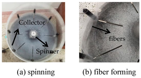
Figure 1.
Preparation of PU/PAN fiber diaphragm by centrifugal spinning.
Through a large number of experiments completed in the early stage, the preparation scheme of different mass fraction PU/PAN nanofiber septa is shown in Table 1; the mass fraction of 18%PU/PAN solution can spin a large number of uniform fibers, this is because due to the high viscosity polymer solution is a non-Newtonian liquid, when the sum of the mass of PU/PAN is less than 18% of the total mass of the mixed solution, due to the polymer solution concentration is low, its viscosity is also low, in the centrifugal spinning process cannot form enough viscoelastic to withstand the external force of the stretch, while the high solvent content, in the spinning process, cannot be completely evaporated, so the fibers appear adhesion phenomenon, the diameter of the ejected fibers is large, and the standard deviation is large, so cannot form a uniform distribution of fiber film, resulting in low porosity of the diaphragm. When the sum of the mass of PU/PAN as a percentage of the total mass of the mixed solution is greater than 18%, the higher polymer solution concentration will lead to a larger viscosity and longer stress relaxation time, thus limiting the jet stretching and thinning, resulting in an oversized diameter of the jets of fibrous film [28,29], so the choice of needle aperture selection 26 G, centrifugal spinning machine speed set to 4200 r/min, the ratio of PU/PAN solution with a mass fraction of 18%.

Table 1.
Preparation schemes of PU/PAN nanofiber separators with different mass fractions.
The optimum solution ratios were also determined by varying the ratio of PU and PAN. The preparation schemes for different ratios of PU/PAN nanofiber diaphragms are shown in Table 2. When PU:PAN = 7:3 and PU:PAN = 8:2, a large number of uniform nanofibers were produced on the collector and were able to be pressed into nanofiber diaphragms, but other solution ratios produced a smaller number of fibers, considering that it may be due to the better spinnability of PU. Therefore, the mass fractions of 18% PU, 18% PU:PAN = 8:2, and 18% PU:PAN = 7:3 were chosen for comparative studies in this paper.
Table 2.
Preparation Scheme of PU/PAN Nanofiber Membrane with different ratios.
2.3. PU/PAN Diaphragm Performance Testing and Structural Characterization
- (1)
- Morphological characterization
Scanning electron microscopy (SEM: GeminiSEM 300, Zeiss, Jena, Germany) was used to observe the surface morphology and determine the fiber diameter and pore size of the PU-based lithium-ion battery diaphragm. The diaphragm samples were first cut, then gold sprayed for 2 min. The freshly prepared PU-based fiber diaphragm film was placed under the microscope for morphological characterization.
- (2)
- Porosity test
An n-butanol aspiration technique was used to determine the diaphragm porosity. First, the diaphragm was cut into 2 cm × 2 cm test samples, then the mass of the dry film without n-butanol was measured. The dry diaphragm was then soaked in an n-butanol solution for 3 h. The residual n-butanol on the surface of the diaphragm was removed with paper, and the mass of the diaphragm was measured. The formula used to calculate the diaphragm porosity was as follows:
where P is the porosity of the diaphragm (%); is the weight after wetting (g); is the dry weight before wetting (g); is the density of n-butanol (g/cm3); and v is the volume of the dried septum (cm3).
- (3)
- Absorption rate test
The diaphragm was dried under a vacuum, and the dry weight was recorded. The diaphragm was then immersed in the electrolyte, and the electrolyte was dried with 1 mol/L lithium hexafluorophosphate (LiPF6) and ethylene carbonate (EC)/methyl ethyl carbonate (EMC)/dimethyl carbonate (DMC) (mass fraction ratio = 1/1/1) for 10 h. The residual electrolyte attached to the surface was removed with paper, and the diaphragm was weighed again. After measuring the mass of the wet film, the absorption rate was calculated as follows:
where is the liquid absorption rate of the diaphragm (%); is the weight after wetting (g); is the dry weight before wetting (g).
- (4)
- Ion conductivity test
An electrochemical workstation was used to measure the ionic conductivity of the commercial Celgard 2400 diaphragm, which consists of PU-based fiber films. A sample of the diaphragm was placed between two steel sheets, and a button cell in the order of steel sheet/diaphragm/steel sheet was assembled in a super clean glove box on an electrochemical workstation. A scan frequency range from 1 MHz to 1 Hz with an amplitude of 5 mV was applied, and the intercept between the high-frequency region and the horizontal axis was expressed as the bulk resistance of the diaphragm. The ionic conductivity of the diaphragm was obtained from the magnitude of the bulk resistance according to Equation:
where is the ionic conductivity (mS/cm); d is the thickness of the diaphragm (cm); s is the cross-sectional area of the diaphragm (cm2); is the bulk resistance of the diaphragm (Ω).
- (5)
- Thermal stability test
To test the thermal stability of the lithium-ion battery diaphragm, samples of the Celgard 2400 and PU/PAN fiber diaphragms (approximately 4 mg each) were placed in a crucible. The crucible was sealed and placed into a thermogravimetric analyzer (TG209F1 Netzsch, Bayern, Germany) for a thermal stability analysis. The test was conducted in a nitrogen atmosphere (50 mL/min) with 10 mL/min of purge gas, and the temperature was ramped up from 20 to 800 °C at a rate of 10 °C/min.
A differential scanning calorimetry (DSC) method was then applied. Approximately 4 mg samples of the Celgard 2400 and PU/PAN fiber diaphragms were placed in an aluminum crucible. The crucible was sealed and placed into a calorimeter (MDSC 2920, TA Instruments, New Castle, DE, USA) to measure the melting point (Tm) of the diaphragm samples. The test was conducted in a nitrogen atmosphere (20 mL/min), and the temperature was ramped up from 20 °C to 350 °C at 10 °C/min, then cooled down to −70 °C also at 10 °C/min.
- (6)
- Electrochemical stability test
The electrochemical stability window refers to the period in which the battery is undergoing an electrochemical reaction. The diaphragm can maintain a stable performance during the most positive and most negative potential intervals, and it does not produce any decomposition reaction. The electrochemical stability of the diaphragm was analyzed when the battery was tested for charge and discharge. A button cell was assembled in a super clean glove box with a sequence of lithium/electrolyte/diaphragm/electrolyte/steel. The electrochemical stability of the different types of diaphragm was characterized by cyclic scanning voltammetry (LSV) in the voltage range of 2.5–6.0 V and at a scan rate of 10 mV/s.
- (7)
- Evaluation of the battery performance
In this study, we used the Xinwei battery testing equipment (Shenzhen Xinwei Electronics Co., Ltd., Shenzen, China) to test the cycle performance, first charge/discharge, and multiplier performance of a CR2032 coin cell. In the super purification glove box (Water content < 1 PPM, oxygen content < 1 PPM), in the battery with lithium iron phosphate (LiFePO4) as the positive electrode and lithium metal as the negative electrode, the battery was assembled with a battery assembly sequence of cathode sheet/electrolyte/diaphragm/electrolyte/lithium sheet, then the program was set to determine the battery performance.
3. Results and Discussion
3.1. Analysis of the Septum Morphology
Both PU and PU/PAN nanofiber diaphragms were prepared by a centrifugal spinning device that was constructed in-house. To observe the effect of PAN addition on the microscopic morphology of the PU/PAN composite diaphragm, the PU and PU/PAN membranes were characterized using SEM. As shown in Figure 2, the PU nanofiber membrane prepared based on the centrifugal spinning method, with a mass fraction of 18%, had a smooth surface with uneven fiber thickness and appeared as a series of spindles. Additionally, the PU nanofibers displayed arbitrary bending. As shown in Figure 3, with the addition of PAN, when 18% PU/PAN = 8:2, the fiber surface mesh structure and fiber diameter were more uniform, but the phenomenon of fiber entanglement aggregation was still apparent. As shown in Figure 4, when 18% PU/PAN = 7:3, the fiber surface was smooth and had a more uniform diameter. The fiber morphology was very good, and there were large, interconnected voids between the fibers, forming a 3D porous structure, while PAN had good spinnability. The use of a PU-based nanofiber diaphragm in the lithium-ion battery charging and discharging process could prevent a battery internal short circuit.
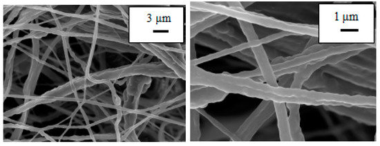
Figure 2.
SEM images of an 18%PU fiber membrane.
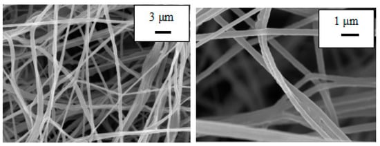
Figure 3.
SEM images of an 18% PU:PAN = 8:2 fiber membrane.
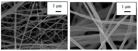
Figure 4.
SEM images of an 18% PU:PAN = 7:3 fiber membrane.
3.2. Analysis of Porosity
The role of lithium-ion battery diaphragm is not only to separate the positive and negative electrodes but, more importantly, to provide a channel for the transport of lithium-ions, a higher porosity helps to promote electrolyte absorption, making lithium-ion transfer more efficient. The absorption rate of the diaphragm also indirectly reflects the porosity, and the performance of both has an important impact on the ionic conductivity, internal resistance, and cycle life of the battery [30]. The test results are shown in Table 3. As the commercial Celgard 2400 diaphragm is not hydrophilic, the affinity for n-butanol was relatively poor, and the diaphragm porosity was only 38%. Cheng C et al. [13] prepared filled ceramic (Al2O3) materials in polyurethane (PU) and used an electrostatic spinning technique to prepare new PUC diaphragms with three-dimensional structure, whose porosity was only 63.7%. The centrifugal spinning process relies on its unique fiber film-forming mode. Both PAN and PU have excellent spinnability, and PU-based and PU/PAN composite diaphragms were obtained. The porosity of the PU/PAN fiber diaphragms were relatively high. The porosity of the pure PU diaphragm was 82.2%, and when 18% PU:PAN = 8:2 and 18% PU:PAN = 7:3, the porosities were 83.5% and 83.9%, respectively. In the PU/PAN composite diaphragm, as the percentage of PAN in the polymer solution increased, the porosity of the diaphragm increased accordingly. The porosity of the PU-based nanofiber diaphragm was higher than the commercial Celgard 2400 diaphragm, indicating that the PU-based diaphragm was more capable of preserving the electrolyte, which promoted the rapid transfer of lithium-ions. Therefore, the PU/PAN composite diaphragm also had a better electrochemical performance than the PU diaphragm.
Table 3.
Porosity and electrolyte absorption of the commercial Celgard 2400 and PU/PAN fiber diaphragms.
3.3. Analysis of the Electrolyte Absorption Rate
The level of diaphragm absorption is usually determined by the porosity, which can hold a certain amount of electrolyte; the more pores, the more the diaphragm can hold the electrolyte, and the absorption rate of the diaphragm increases [31]. As shown in Table 3, the lowest electrolyte absorption rates were 116% for the Celgard 2400 diaphragm, 412% for the PU diaphragm, and 454% and 493% for 18% PU:PAN = 8:2 and 18% PU:PAN = 7:3 diaphragms, respectively. In the PU/PAN composite diaphragm, the electrolyte absorption rate increased as the proportional content of PAN increased. Compared to the Sb2O3-modified polyvinylidene fluoride-co-chlorotrifluoroethylene (PVDF-CTFE) fiber membrane prepared by Wang L et al. [32] with an absorption rate of only 356%. This was due to the presence of the nitrile group (CN) in PAN, which interacted with Li+ for better liquid retention. The commercial Celgard 2400 diaphragm had a relatively poor wettability by electrolytes, but due to its unique chemical structure and highly interconnected porous structure between fibers, the porous PU-based film was readily wettable by electrolytes. The strong polar organic group (-CN) in PAN had good interfacial compatibility with polar electrolytes, which improved the absorption capacity of electrolytes, and also directly affected the ionic conductivity of the PU/PAN lithium-ion battery diaphragm.
3.4. Analysis of the Ionic Conductivity
The ionic conductivity reflects how fast the lithium-ions migrate between the positive and negative electrodes during the operation of a lithium-ion battery and indirectly reflects the size of the diaphragm resistance. The larger the diaphragm resistance, the smaller its ionic conductivity; the slower the rate of lithium-ion transfer in the battery, and the poorer the performance of the battery exhibited [23]. Figure 5 is an impedance diagram of the commercial Celgard 2400 and PU/PAN fiber diaphragms. The intercept on the horizontal axis represents the bulk resistance of the diaphragm. The ionic conductivity of the Celgard 2400 diaphragm was only 0.82 mS/cm, as obtained by Equation (3), but the ionic conductivity of the PU/PAN fiber diaphragms was improved due to their 3D mesh structure resulting from the centrifugal spinning method. In the same size diaphragm, more electrolytes can be absorbed and provides a large number of channels for lithium-ion penetration in the diaphragm [33]. This structure improved the transport rate of lithium-ions in the fiber diaphragm.
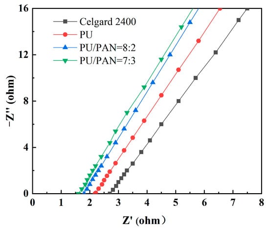
Figure 5.
Impedance diagram of the commercial Celgard 2400 and PU/PAN fiber diaphragms.
The ionic conductivities of 18% PU, 18% PU:PAN = 8:2, and 18% PU:PAN = 7:3 fiber septa were 1.43 mS/cm, 1.68 mS/cm, and 1.79 mS/cm, respectively. The ionic conductivity of the fiber septa increased with the increasing PAN content and was highest at 18% PU:PAN = 7:3. This was because the addition of PAN enhanced the liquid absorption and retention capacity of the diaphragm. Additionally, in the diaphragm of the hot-pressing process, the fibrous filaments did not melt and form physical cross-linking, and its body resistance did not increase. The performance of the PU-based lithium-ion battery diaphragm was better than that of the commercial diaphragm and could meet the high conductivity requirement in lithium-ion batteries.
3.5. Analysis of the Thermal Stability
The thermal stability of the diaphragm is critical to the safety of lithium-ion batteries and is an extremely important indicator. Batteries often charge and discharge at high rates, and the internal temperature of the battery is prone to rise. This results in a severe contraction of the lithium-ion battery diaphragm, which can cause a short circuit in direct contact with the positive and negative electrodes of the battery. To compare the thermal stability of the Celgard 2400 and PU/PAN fiber diaphragms, a thermal weight loss analysis was conducted with the results shown in Figure 6. The Celgard 2400 diaphragm started to show significant thermal decomposition at about 400 to 700 °C, with a residual mass retention rate of no more than 2%, while thermal weight loss of PU/PAN fiber diaphragms occurred from 310 °C to 450 °C. This part of the mass loss is the thermal decomposition of PU caused by the destruction of the structure at high temperatures and was then stable until the temperature reached 700 °C. The final mass retentions of the PU, 18% PU:PAN = 8:2, and 18% PU:PAN = 7:3 diaphragms were 5.4%, 17.2%, and 32.1%, respectively, which showed that PAN addition did not reduce the thermal stability of PU/PAN fiber diaphragms and could improve their residual mass retention. So, the addition of PAN will reduce the mass loss of the composite diaphragm and improve the thermal stability of the diaphragm, meeting the thermal stability requirements of lithium-ion battery separators. The DSC results for the Celgard 2400 and PU/PAN fiber diaphragms are shown in Figure 7. The heat absorption peak of the Celgard 2400 diaphragm appeared at 118 °C, indicating that the melting point of the Celgard 2400 diaphragm was 118 °C, while the heat absorption peaks of the PU, 18% PU:PAN = 8:2, and 18% PU:PAN = 7:3 diaphragms appeared at 300 °C, 308 °C, and 314 °C, respectively, indicating that their melting points were 300 °C, 308 °C, and 314 °C, respectively. In summary, the thermal stabilities of the PU/PAN fiber diaphragms were better than that of the commercial Celgard 2400 diaphragm because the polymer chain segments in the composite diaphragms were separated, while in the commercial diaphragm they were in a taut state.
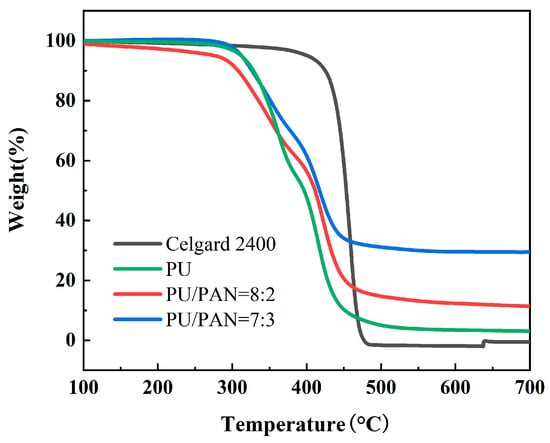
Figure 6.
Thermal weight loss analysis of the commercial Celgard 2400 and PU/PAN fiber diaphragms.
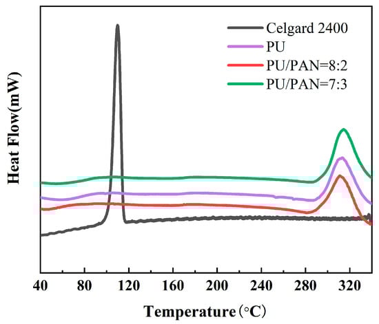
Figure 7.
The DSC test results for the commercial Celgard 2400 and PU/PAN fiber diaphragms.
The thermal dimensional stability of the diaphragm is another important indicator of battery safety performance. Portions of the Celgard 2400 and PU/PAN fiber diaphragms were cut into samples of the same size and shape, and then subjected to a heat treatment at 160 °C for 30 min.
The changes in the dimensions of the different diaphragms are shown in Figure 8. After the heat treatment, the commercial Celgard 2400 diaphragm was no longer a film, while there were no significant dimensional changes in the PU/PAN fiber diaphragms. The thermal dimensional stability of the PU/PAN fiber diaphragms was significantly better than that of the commercial Celgard 2400 diaphragm, compared to polyacrylonitrile (PAN)/styrene-isoprene-styrene (SIS) composite fiber membranes prepared by Tang et al. [24] using electrostatic spinning, PAN/SIS composite fiber membranes curled after heat treatment at 160 °C. PU-based fiber membranes possess advantages as candidates for lithium-ion battery separators.
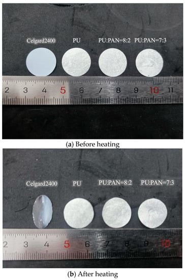
Figure 8.
Thermal dimensional stability test results of the commercial Celgard 2400 and PU/PAN fiber diaphragms.
3.6. Analysis of Electrochemical Stability
Electrochemical stability is an important performance parameter for lithium-ion battery diaphragms, which must maintain the stability of the electrolyte and electrode in terms of electrochemical properties to avoid degradation during the charge and discharge process. A high electrochemical stability window facilitates the long-term stable operation of Li-ion batteries at a high voltage. To evaluate the electrochemical stability of the diaphragm, the potential range was set to 2.5 V–6.0 V to perform LSV tests on the Celgard 2400 and PU/PAN fiber diaphragms. Figure 9 shows that the electrochemical stability windows of the PU, PU/PAN = 8:2, and PU/PAN = 7:3 diaphragms were 4.8 V, 5.1 V, and 5.2 V, respectively, which were much larger than the 4.3 V obtained for the commercial Celgard 2400 diaphragm, as shown by the voltage corresponding to the sudden increase in current. This was attributed to the strong chemical stability of the PU/PAN fiber diaphragms, and the increased PAN content also improved the electrochemical stability window. Li L et al. [11] prepared PAN/polyimide (PI) composite films by electrostatic spinning to improve the electrochemical performance of a single PAN diaphragm with an electrochemical stability window of about 4.0 V. The centrifugal spinning method used to prepare the PU, PU/PAN = 8:2, and PU/PAN = 7:3 diaphragms resulted in a wide electrochemical stability window. Lithium-ion batteries with a wide electrochemical stability window will charge and discharge without degradation. The PU/PAN fiber diaphragms showed a good electrolyte affinity, and the excellent electrochemical stability of PU/PAN composite diaphragm allows it to have better compatibility with the cathode material in lithium-ion batteries, which can be applied to work in adverse environments, such as high voltage.
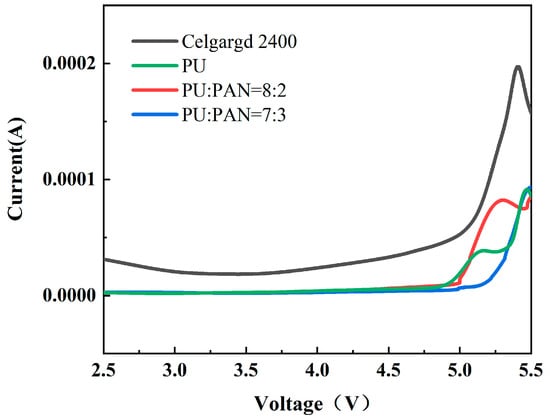
Figure 9.
Linear scan diagram of the commercial Celgard 2400 and PU/PAN fiber diaphragms.
3.7. Analysis of the Battery Charging, Discharging, and Cycling Performance
Lithium metal as the negative electrode, LiFePO4 as the positive electrode, and PU and PU/PAN lithium-ion battery diaphragms were used to assemble lithium-ion batteries. An analysis was conducted to determine whether PU/PAN fiber diaphragms could be applied to rechargeable lithium-ion batteries by comparing the charge and discharge performance and cycle stability of the batteries. The first discharge performance of the PU and PU/PAN composite diaphragm was compared with the commercial Celgard 2400 diaphragm at a current density of 0.2 C rate, as shown in Figure 10. The first discharge-specific capacities of PU, 18% PU:PAN = 8:2, and 18% PU:PAN = 7:3 nanofiber diaphragm batteries were 148.1 mAh/g and 152.6 mAh/g. Sabetzadeh N et al. [31] prepared porous polyacrylonitrile (PAN) nanofiber diaphragm by electrostatic spinning method, and its first discharge specific capacity at 0.1 C magnification was only 130 mAh/g. The high porosity of the PU diaphragm enables it to absorb more electrolyte, which provides an efficient channel for lithium-ion transfer between positive and negative electrodes, and at the same time, the interface stability between PAN and electrode material The high porosity of the PU diaphragm enables it to absorb more electrolyte, providing an efficient channel for the transfer of lithium-ions between the cathode and cathode, and the good interfacial stability between the PAN and electrode materials, which gives the PU/PAN diaphragm a high first discharge capacity. With the increase in charging and discharging times, the porosity, liquid absorption rate, and ionic conductivity of the diaphragm decreased, and the discharge-specific capacity of lithium-ion batteries decreased [34]. The cycling performances of the PU/PAN fiber diaphragms were compared with that of the commercial Celgard 2400 diaphragm at a current density of 0.2 C rate, as shown in Figure 11. Due to the poor absorption of electrolytes by the Celgard 2400 diaphragm, the specific capacity of the first discharge was only 144.6 mAh/g. After 50 cycles, the discharge-specific capacity remained at 137 mAh/g, with a capacity retention rate of only 94.7%, while the remaining discharge-specific capacities of 18% PU:PAN = 8:2, 18% PU:PAN = 7:3, and 18% PU after 50 cycles were 145.3 mAh/g, 147.1 mAh/g, and 140.5 mAh/g, respectively, with capacity retention rates of 95.2%, 95.8%, and 94.9%. The capacity retentions of the PU/PAN fiber diaphragms were higher than that of the Celgard 2400 diaphragm, with an excellent charge/discharge performance and cycle stability. This was due to the better compatibility of the PU/PAN fiber diaphragms with the electrolyte, and the existence of large interconnecting voids and the 3D mesh structure of the PU/PAN fiber diaphragms, which increases its ionic conductivity and suppresses the decrease in discharge specific capacity. Therefore, the PU/PAN fiber diaphragms have the potential to be used in rechargeable lithium-ion batteries.
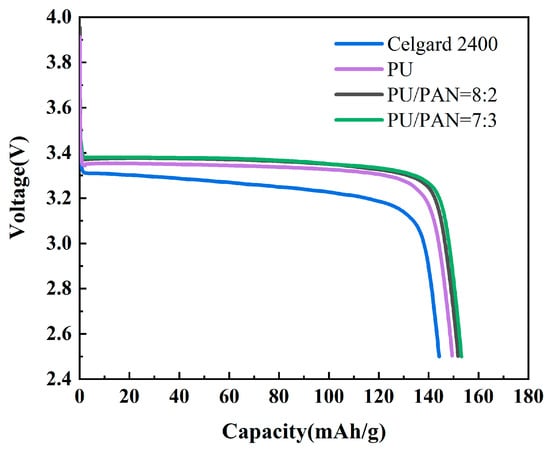
Figure 10.
First discharge curve of batteries using commercial Celgard 2400 and PU/PAN fiber diaphragms at 0.2 C rate.
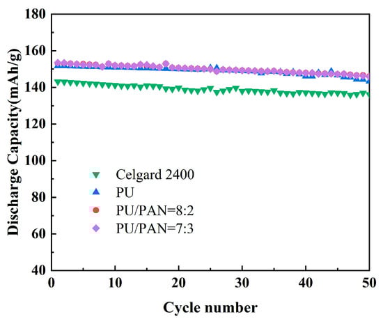
Figure 11.
Cyclic performance of batteries with commercial Celgard 2400 and PU/PAN fiber diaphragms at 0.2 C rate.
3.8. Battery Multiplier Performance
High-power and large-capacity lithium-ion batteries are required in high-performance electronic devices, electric vehicles, and other applications. Therefore, the ability of PU and PU/PAN composite diaphragm-assembled batteries to be used under large multiplier charge and discharge conditions is critical. Battery charging and discharging under large multiplier conditions can cause heat to collect in the cell and reduce the battery life. To characterize the performance of the diaphragm for charging and discharging at large multipliers, corresponding multiplier performance tests were performed. Figure 12 shows the multiplier performance plots of the commercial Celgard 2400 and PU/PAN fiber diaphragms in assembled lithium-ion batteries at a different rate. The discharge capacity of lithium-ion batteries assembled with PU/PAN fiber diaphragms was higher than that of the Celgard 2400 diaphragm at 0.2 C, 0.5 C, 1 C, 2 C, and 5 C rates. The lowest discharge capacity was recorded for lithium-ion batteries fitted with a Celgard 2400 diaphragm. This was because PU/PAN fiber diaphragms contained many polar groups that could absorb more electrolytes, and the diaphragm had a low internal resistance and low loss, resulting in a higher discharge capacity.
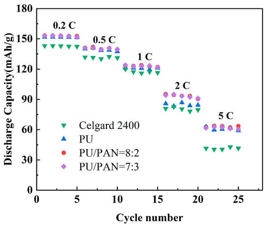
Figure 12.
Battery multiplier performance of commercial Celgard 2400 and PU/PAN fiber diaphragms.
4. Conclusions
A centrifugal spinning method was used to prepare a PU/PAN lithium-ion battery diaphragm by blending with different ratios of PAN. The properties of the PU/PAN lithium-ion battery diaphragms were characterized in this study. The results showed that the fiber films obtained at the blending ratios of 18% PU/PAN = 8:2 and 18% PU/PAN = 7:3 had a good 3D mesh structure. When 18% PU:PAN = 7:3, the PU/PAN composite fiber film had the most uniform diameter distribution, the porosity was 83.9%, the liquid absorption rate was 493%, and the thermal stability also displayed a corresponding increase with the increasing PAN content. When 18% PU:PAN = 7:3, the ionic conductivity of the fiber diaphragm increased to 1.79 mS/cm and the electrochemical stability window increased to 5.2 V, with a higher ionic conductivity and wider electrochemical stability window than the commercial Celgard 2400 diaphragm. In lithium-ion batteries assembled with LiFePO4 as the cathode material, after 50 cycles at 0.2 C rate, the discharge specific capacity of the PU/PAN lithium-ion battery diaphragm could still be maintained at 147.1 mAh/g, with a capacity retention rate of 95.8%. Additionally, a high discharge specific capacity was maintained under different multiplier conditions, with an excellent charge/discharge cycle stability and multiplier performance. The application of PU and PAN blending can improve the performance of a single PU matrix, and the resulting membrane can be used as the preferred material for high performance lithium-ion battery separators.
Meanwhile, the preparation method of PU/PAN nanofiber diaphragm based on centrifugal spinning method proposed in this paper is characterized by high preparation efficiency and suitable for industrial production; further optimization of co-blending formula and process parameters for different polymer materials and different nanofiber membrane performance requirements is a direction worthy of in-depth research in the future, which is of great significance for industrial production of nanofiber membrane.
Author Contributions
Methodology, L.C.; Formal analysis, Y.W.; Writing—original draft, T.L.; Writing—review & editing, S.M. All authors have read and agreed to the published version of the manuscript.
Funding
This work was supported by The scientific research plan of the national high-end textile equipment research base (111HTE2022002) and The National Science Foundation of China of China (No. 51175385).
Institutional Review Board Statement
Not applicable.
Informed Consent Statement
Not applicable.
Conflicts of Interest
The authors declare no conflict of interest.
References
- Lu, C.M.; Wang, L.H.; Chu, J.; Yu, X.H. Preparation of PBI/PEI high absorption lithium-ion battery separators by VIPS method. J. Membr. Sci. 2022, 42, 23–31. [Google Scholar]
- Sun, G.H.; Cui, J.Q.; Wang, Y.; Zhang, X.; Ma, J.S.; Hou, L.L. Research progress on heat-resistant polymer lithium-ion battery separators. Chin. J. of Plast. 2022, 36, 190–194. [Google Scholar]
- He, Y.J.; Lu, Z.H.; Zhang, H.; Liu, L.Q.; An, X.Y.; Liu, H.B.; Cao, H.B.; Lu, B. Research progress and application prospects of paper based battery separators. Trans. Tianjin Univ. 2019, 41, 14–20. [Google Scholar]
- Li, A.; Yuen, A.C.Y.; Wang, W.; De Cachinho Cordeiro, I.M.; Wang, C.; Chen, T.B.Y.; Zhang, J.; Chan, Q.N.; Yeoh, G.H. A review on lithium-ion battery separators towards enhanced safety performances and modelling approaches. Molecules 2021, 26, 478. [Google Scholar] [CrossRef]
- Lv, D.; Chai, J.; Wang, P.; Zhu, L.; Liu, C.; Nie, S.; Li, B.; Cui, G. Pure cellulose lithium-ion battery separator with tunable pore size and improved working stability by cellulose nanofibrils. Carbohydr. Polym. 2021, 251, 116975. [Google Scholar] [CrossRef]
- Wu, D.; Dong, N.; Wang, R.; Qi, S.; Liu, B.; Wu, D. In situ construction of high-safety and non-flammable polyimide “ceramic” lithium-ion battery separator via SiO2 nano-encapsulation. J. Chem. Eng. 2021, 420, 129992. [Google Scholar] [CrossRef]
- Sun, G.; Guo, J.; Niu, H.; Chen, N.; Zhang, M.; Tian, G.; Qi, S.; Wu, D. The design of a multifunctional separator regulating the lithium ion flux for advanced lithium-ion batteries. RSC Adv. 2019, 9, 40084–40091. [Google Scholar] [CrossRef] [PubMed]
- Bicy, K.; Gueye, A.B.; Rouxel, D.; Kalarikkal, N.; Thomas, S. Lithium-ion battery separators based on electrospun PVDF: A review. Surf. Interfaces 2022, 2022, 101977. [Google Scholar] [CrossRef]
- Zhang, D.; Ding, L.; Wu, T.; Yang, F.; Lan, F.; Cao, Y.; Xiang, M. Facile preparation of a lithium-ion battery separator with thermal shutdown function based on polypropylene/polyethylene microsphere composites. Ind. Eng. Chem. Res. 2021, 60, 18530–18539. [Google Scholar] [CrossRef]
- Dahe, G.J.; Teotia, R.S.; Bellare, J.R. Correlation between spinning temperature, membrane morphology, and performance of Psf/PVP/NMP/Water hollow fiber membrane forming system. J. Appl. Polym. Sci. 2012, 124, E124. [Google Scholar] [CrossRef]
- Li, L.; Liu, P.; Fu, Q.S.; Gong, Y.; Zhang, S.R.; He, H.J.; Chen, J. Study on preparation of polyacrylonitrile/polyimide composite lithium-ion battery separator by electrospinning. J. Mater. Res. 2019, 34, 642–651. [Google Scholar] [CrossRef]
- Khan, W.S.; Asmatulu, R.; Rodriguez, V.; Ceylan, M. Enhancing thermal and ionic conductivities of electrospun PAN and PMMA nanofibers by graphene nanoflake additions for battery-separator applications. Int. J. Energy Res. 2014, 38, 2044–2051. [Google Scholar] [CrossRef]
- Cheng, C.; Liu, H.; Ouyang, C.; Hu, N.; Zha, G.; Hou, H. A high-temperature stable composite polyurethane separator coated Al2O3 particles for lithium ion battery. Compos. Commun. 2022, 33, 101217. [Google Scholar] [CrossRef]
- Fang, Y.; Dulaney, A.R.; Gadley, J.; Maia, J.; Ellison, C.J. A comparative parameter study: Controlling fiber diameter and diameter distribution in centrifugal spinning of photocurable monomers. Polymer 2016, 88, 102–111. [Google Scholar] [CrossRef]
- Wang, J.; Zhao, Y.; Zhu, S.; Tian, W.; Qu, L. Development and application of centrifugal spinning technology. Shandong Text. Technol. 2019, 2, 52–55. [Google Scholar]
- Yanilmaz, M.; Zhang, X. Polymethylmethacrylate/polyacrylonitrile membranes via centrifugal spinning as separator in Li-ion batteries. Polymers 2015, 7, 629–643. [Google Scholar] [CrossRef]
- Lv, R.; Zhu, Y.; Liu, H.; Na, B.; Huang, Y.; Xie, X. Poly(vinylidene fluoride)/poly(acrylonitrile) blend fibrous membranes by centrifugal spinning for high-performance lithium ion battery separators. J. Appl. Polym. Sci. 2017, 134, 44515. [Google Scholar] [CrossRef]
- Xie, J.; Fu, C.; Liao, C.; Juang, R.; Gandomi, Y.A. Alumina nanocoating of polymer separators for enhanced thermal and electrochemical performance of Li–ion batteries. Asia-Pac. J. Chem. Eng. 2019, 14, e2335. [Google Scholar] [CrossRef]
- Cho, J.; Jung, Y.C.; Lee, Y.S.; Kim, D.W. High performance separator coated with amino-functionalized SiO2 particles for safety enhanced lithium-ion batteries. J. Membr. Sci. 2017, 535, 151–157. [Google Scholar] [CrossRef]
- Yang, Y.; Yang, B.; Luo, M.; Yang, Y.; Wang, Y.; Miao, J.; Tu, Y. Considerably enhanced electrochemical and thermomechanical performance of lithium battery (LIB) separators of PVDF/vermiculite nanosheets (VNs) composites via constructing well-defined hierarchical microstructure. Electrochim. Acta 2023, 446, 142074. [Google Scholar] [CrossRef]
- Cai, M.; Yuan, D.; Zhang, X.; Pu, Y.; Liu, X.; He, H.; Zhang, L.; Ning, X. Lithium ion battery separator with improved performance via side-by-side bicomponent electrospinning of PVDF-HFP/PI followed by 3D thermal crosslinking. J. Power Sources 2020, 461, 228123. [Google Scholar] [CrossRef]
- Wu, Q.-Y.; Liang, H.-Q.; Gu, L.; Yu, Y.; Huang, Y.-Q.; Xu, Z.-K. PVDF/PAN blend separators via thermally induced phase separation for lithium ion batteries. Polymer 2016, 107, 54–60. [Google Scholar] [CrossRef]
- Khodaverdi, F.; Vaziri, A.; Javanbakht, M.; Jahanfar, M. Improvement of PAN separator properties using PVA/malonic acid by electrospinning in lithium-ion batteries. J. Appl. Polym. Sci. 2021, 138, 50088. [Google Scholar] [CrossRef]
- Tang, C.Y.; He, Y.; Li, L.; Liu, P.; Chen, J. Study on the preparation of PAN/SIS composite lithium-ion battery separators by electrospinning method. Insul. Mater. 2021, 54, 75–79. [Google Scholar]
- Wang, Y.Q.; Xue, X.J. Research progress of lithium battery gel polymer electrolyte. Henan Chem. Ind. 2017, 34, 12–17. [Google Scholar]
- Zhang, Y.; Li, T.-T.; Shiu, B.-C.; Sun, F.; Ren, H.-T.; Zhang, X.; Lou, C.-W.; Lin, J.-H. Eco-friendly versatile protective polyurethane/triclosan coated polylactic acid nonwovens for medical covers application. J. Clean. Prod. 2021, 282, 124455. [Google Scholar] [CrossRef]
- Ke, H.M.; Zhu, R.P.; Ma, J.H.; Gong, J.H. Preparation and properties of halogen-free flame retardant polyurethane for superfine fiber leather. Mater. Sci. Forum. 2020, 993, 669–677. [Google Scholar] [CrossRef]
- Sharma, P.; Bora, B.J. A Review of Modern Machine Learning Techniques in the Prediction of Remaining Useful Life of Lithium-Ion Batteries. Batteries. 2022, 9, 13. [Google Scholar] [CrossRef]
- Wanatasanappan, V.V.; Kanti, P.K.; Sharma, P.; Husna, N.; Abdullah, M.Z. Viscosity and rheological behavior of Al2O3-Fe2O3/water-EG based hybrid nanofluid: A new correlation based on mixture ratio. J. Mol. Liq. 2023, 375, 121365. [Google Scholar] [CrossRef]
- Li, Y.; Li, Q.; Tan, Z. A review of electrospun nanofiber-based separators for rechargeable lithium-ion batteries. J. Power Sources 2019, 443, 227262. [Google Scholar] [CrossRef]
- Sabetzadeh, N.; Gharehaghaji, A.A.; Javanbakht, M. Porous PAN micro/nanofiber separators for enhanced lithium-ion battery performance. Solid State Ion. 2018, 325, 251–257. [Google Scholar] [CrossRef]
- Wang, L.; Wang, Z.; Sun, Y.; Liang, X.; Xiang, H. Sb2O3 modified PVDF-CTFE electrospun fibrous membrane as a safe lithium-ion battery separator. J. Membr. Sci. 2019, 572, 512–519. [Google Scholar]
- Chen, P.; Shen, J.; Wang, T.; Dai, M.; Si, C.; Xie, J.; Li, M.; Cong, X.; Sun, X. Zeolitic imidazolate framework-67 based separator for enhanced high thermal stability of lithium ion battery. J. Power Sources 2018, 400, 325–332. [Google Scholar] [CrossRef]
- Qiao, Y.; Li, S.-R.; Yu, Y.; Chen, C.-H. Synthesis and electrochemical properties of high performance yolk-structured LiMn2O4 microspheres for lithium ion batteries. J. Mater. Chem. A 2013, 1, 860–867. [Google Scholar] [CrossRef]
Disclaimer/Publisher’s Note: The statements, opinions and data contained in all publications are solely those of the individual author(s) and contributor(s) and not of MDPI and/or the editor(s). MDPI and/or the editor(s) disclaim responsibility for any injury to people or property resulting from any ideas, methods, instructions or products referred to in the content. |
© 2023 by the authors. Licensee MDPI, Basel, Switzerland. This article is an open access article distributed under the terms and conditions of the Creative Commons Attribution (CC BY) license (https://creativecommons.org/licenses/by/4.0/).