Article

Hierarchical Two-Stage Robust Planning for Demand-Side Energy Storage with Dynamic Carbon Incentive Mechanism

1
College of Electrical Engineering, Zhejiang University, Hangzhou 310027, China
2
State Grid Zhejiang Electric Power Co., Ltd., Hangzhou 310007, China
3
School of Electric Power Engineering, South China University of Technology, Guangzhou 510641, China
4
National Power Dispatching and Control Center, State Grid Corporation of China, Beijing 100031, China
*
Author to whom correspondence should be addressed.
Appl. Sci. 2023, 13(11), 6524; https://doi.org/10.3390/app13116524
Submission received: 25 April 2023 / Revised: 24 May 2023 / Accepted: 25 May 2023 / Published: 26 May 2023
(This article belongs to the Section Electrical, Electronics and Communications Engineering)

Abstract

:
Demand-side energy storage is an important foundation for enhancing load flexibility to accommodate renewable energy. With the widespread adoption of renewable energy, demand-side energy storage planning, and its incentive mechanism have also attracted the attention of a large number of scholars. However, there are still few studies on incentives from a carbon perspective. To fill the gap, a dynamic carbon incentive mechanism is proposed in this study. In addition, a hierarchical two-stage robust planning model for demand-side energy storage that incorporates the proposed carbon incentive mechanism is developed. At the first level, the economic dispatch is performed, and bus carbon intensities are calculated based on the carbon emission flow theory. The second level is a two-stage robust planning model to obtain the optimal capacities of demand-side energy storage, which is solved based on the nested column and constraint generation algorithm. The proposed model is implemented and evaluated on the MATLAB/YALMIP platform using IEEE 24-bus power systems. The results validate the efficacy of the model in promoting carbon-oriented demand-side energy storage planning, leading to a substantial reduction of carbon emissions by 8.44%. Notably, when compared to existing incentive mechanisms, the proposed carbon incentive mechanism exhibits distinct advantages in achieving carbon reduction with less both subsidy costs and fixed investments.

1. Introduction

Under the pressure of the Paris Agreement, countries around the world have proposed carbon peaking and carbon-neutral targets to further implement their carbon emission reduction goals [1,2,3]. For the energy sector, the essence of carbon reduction is to reduce the use of fossil energy and replace it with low-carbon renewable energy [4,5,6]. However, renewable energy sources, e.g., wind power and photovoltaic, are directly dependent on natural energy sources, so the power generated has large intermittency [7,8,9]. Intermittent power exhibits high uncertainty and is difficult to accommodate in the system, resulting in the common phenomenon of wind and solar energy curtailment [10,11,12]. Energy storage is a good partner for renewable energy in practical applications because it can be flexibly charged and discharged like an energy sponge, showing better flexibility [5,13]. Therefore, energy storage planning for systems containing renewable energy has become an international study hotspot in the field.
With the widespread adoption of renewable energy and the development of energy storage technologies, energy storage planning in source-side centralized renewable energy plants has been well studied. Hou et al. [14] proposed a gravity energy storage system tailored for mountainous regions and developed an optimal capacity planning model for an on-grid wind-photovoltaic-storage hybrid power system. Palys et al. [15] employed an optimal combined capacity planning and scheduling model to investigate the economic feasibility of using hydrogen and ammonia for islanded renewable energy storage. Zhang et al. [16] introduced an innovative co-planning model encompassing wind farms, energy storage, and transmission network, accounting for imbalanced power, unit ramp capacity, and renewable energy incentives. Chen et al. [17] focused on the grid-connection transmission line and locally deployed energy storage unit capacities in conjunction with solar plants, exploring the feasible set of capacities. Furthermore, solar thermal storage has gained increasing attention in recent years. Al-Ghussain et al. [18] demonstrated the practicality of integrating thermal storage into renewable power generation systems, highlighting its ability to fulfill 100% of energy requirements and alleviate the demand for more hazardous alternatives. Wang et al. [19] proposed a two-stage decision-making framework for wind and concentrating solar power energy systems, investigating thermal energy storage capacity planning and energy dispatch.
Simultaneously, demand response is gaining more and more attention in the context of increasing uncertainties in the power system. Demand-side energy storage (DES) is the fundamental guarantee to enhance demand response capability and improve load elasticity. Promoting demand-side energy storage planning is both a realistic development need and a way to ease the pressure on electric power companies to invest in energy storage. Chen et al. [20] developed an integrated model for power generation and customer-sited energy storage system expansion planning, examining the impact of customer-sited energy storage systems on the integration of renewable energy. Wang et al. [21] formulated a storage capacity expansion planning model incorporating multiple functions of hybrid energy storage within regional integrated energy systems. They further proposed an operational strategy for hybrid energy storage to actively participate in demand response activities. Shen et al. [22] focused on multi-energy coupling demand response and presented an optimization method for energy storage in microgrids. User-side scenarios are more diverse and relatively blank in research, so demand-side energy storage planning research will be a promising research direction.
The development of demand-side energy storage cannot be achieved without the participation and investment of users or agents. However, current storage costs and electricity market policies do not provide sufficient incentives for deploying a demand-side energy storage [20]. Incentive mechanisms for user-side energy storage are thus indispensable. Huang et al. [23] evaluated two financial incentive mechanisms to promote energy storage investment. These mechanisms involved providing tax credits based on the installed storage capacity or the amount of energy delivered from the storage. Tian et al. [24] investigated the impact of fiscal incentives, specifically production tax credits and investment tax credits, on investment behavior in the energy storage sector. Wang et al. [25] proposed a multi-level incentive electricity prices mechanism for demand response and energy storage systems to address the operational risks of the virtual power plant participating in the short-term electricity market. Wang et al. [26] designed an incentive mechanism for agents strategically investing in solar and battery storage systems to provide incentives to each user involved in the energy-sharing scheme.
However, most existing research has studied incentive mechanisms from an energy or power perspective. Few studies have proposed incentives directly from the perspective of carbon. Therefore, in the context of the decarbonization of energy systems, designing energy storage incentive mechanisms from a carbon perspective is in line with the development trend and has important research significance. Due to the demand-side energy storage capacity planning, it is necessary to clarify the demand-side carbon emission responsibility. Zhou et al. [27] pioneered the carbon emission flow (CEF) theory, which established a strong theoretical basis for designing demand-side energy storage incentive mechanisms from a carbon perspective. Kang et al. [28] proposed an improved CEF theory considering line power losses. The CEF theory can well track the flow of virtual carbon emission in the power system and thus gained popular applications. Wang et al. [29], Wang et al. [30], Wei et al. [31], and Cheng et al. [32] applied CEF theory to the research problem of planning and operation of power or multi-energy coupled systems. Therefore, based on the CEF theory, it is feasible to construct an incentive mechanism for energy storage planning that considers demand-side carbon emission responsibility.
In short, international scholars have made important contributions to demand-side energy storage planning and incentive mechanisms. Still, the design of demand-side energy storage incentive mechanisms from a carbon perspective has not been sufficiently studied. To fill the research gap, this article has conducted some studies with the following main contributions.
(1)
Based on the CEF theory, a dynamic carbon incentive mechanism (DCIM) for demand-side energy storage is proposed. The proposed DCIM can effectively guide the demand-side energy storage carbon-oriented configuration and operation based on dynamic carbon intensities and prices.
(2)
A hierarchical two-stage robust planning model for demand-side energy storage integrating the proposed DCIM is developed in this paper. The first level is obtaining the bus caron intensities through the economic dispatch and CEF model. The second level is a two-stage robust energy storage planning model considering the uncertainties of wind turbine output and power demand.
(3)
Based on the nested column and constraint generation (N-C&CG) algorithm, the model is transformed into a mixed integer linear programming (MILP) problem, and a commercial optimization solver is invoked to solve it. The validity and advantages of the proposed model are then illustrated by numerical analysis of cases.

2. Methodology Statement

2.1. The Proposed DCIM Based on the CEF Theory

Achieving the decarbonization target is an urgent and arduous task. Current research on the decarbonization of the power system pays more attention to the source side. However, urgent decarbonization requires not only efforts at the source side but also to explore the carbon reduction potential on the demand side. The demand-side response capability, including demand-side energy storage, interruptible load, etc., is the source of the demand-side carbon reduction capability. However, most of the current incentives for demand-side response are only from the perspective of maintaining network operation security and peak-shaving and valley-filling, lacking a carbon-oriented incentive. On this basis, a dynamic carbon incentive mechanism based on the CEF theory [27,33,34] is constructed in the article.
Based on the CEF model in [33,34], the bus carbon intensities, which characterize the carbon emission responsibility per unit of electricity, can be expressed as (1).
e i B = j i + ( e j B P j i + e i G P i G ) j i + ( P j i + P i G )
where e i B represents the bus carbon intensity of the bus i ; P i G represents the power generator output; i + represents the set of starting buses of the power flow injected into bus i ; e i G represents the carbon intensities of power generators.
Based on the dynamic carbon intensities of each bus calculated from (1), the carbon incentive proposed in this paper can be expressed as (2).
C i , t C I = p i C e i , t B d i , t D R Δ t
where p i C represents the carbon trading price; d i , t D R represents the demand-side response; e i , t B d i , t D R , therefore, denotes the changes in demand-side carbon responsibilities caused by the carbon-oriented demand-side response; C i , t C I denotes the revenue of carbon-oriented demand-side response, which can be a negative value if the load-side carbon responsibility increase after the demand-side response.

2.2. Uncertainty Modeling of the Load and Wind Power

Instead of pre-determining the probability distribution of uncertain parameters, robust optimization models the uncertainty of parameters by the uncertainty set. Commonly used uncertainty sets belong to box uncertainty sets, polyhedral uncertainty sets, etc. The polyhedral uncertainty sets are adopted in this paper to build the load uncertainty set u L as (3).
u L = P ˜ i , t L | P ˜ i , t L = P i , t L + Δ P i , t L g ˜ i , t L , t = 1 T g ˜ i , t L Γ L , g ˜ i , t L 1 , 1 ,   i Ω L
where P ˜ i , t L and P i , t L denote the uncertain power load and forecast power load, respectively; Δ P i , t L and g ˜ i , t L represent the power load deviation and uncertain variables; Γ L , T and Ω L represent the budget value, period of the optimization and set of power loads, respectively.
For the wind power, a specific polyhedral uncertainty set, called the base uncertainty set, is adopted to better model the wind power uncertainty set u W as (4).
u W = P ˜ i , t W | 0 P ˜ i , t W P N , i W T , t = 1 T P ˜ i , t W P ^ i , t W P ^ i , t W Γ W , i Ω W
where P ˜ i , t W , P N , i W T , and P ^ i , t W represent the uncertain wind power output, wind turbine capacity and expected value of the wind power, respectively; Γ W and Ω W denote the budget valve and the set of wind turbines.

3. The Proposed Hierarchical Two-Stage Robust DES Planning Model

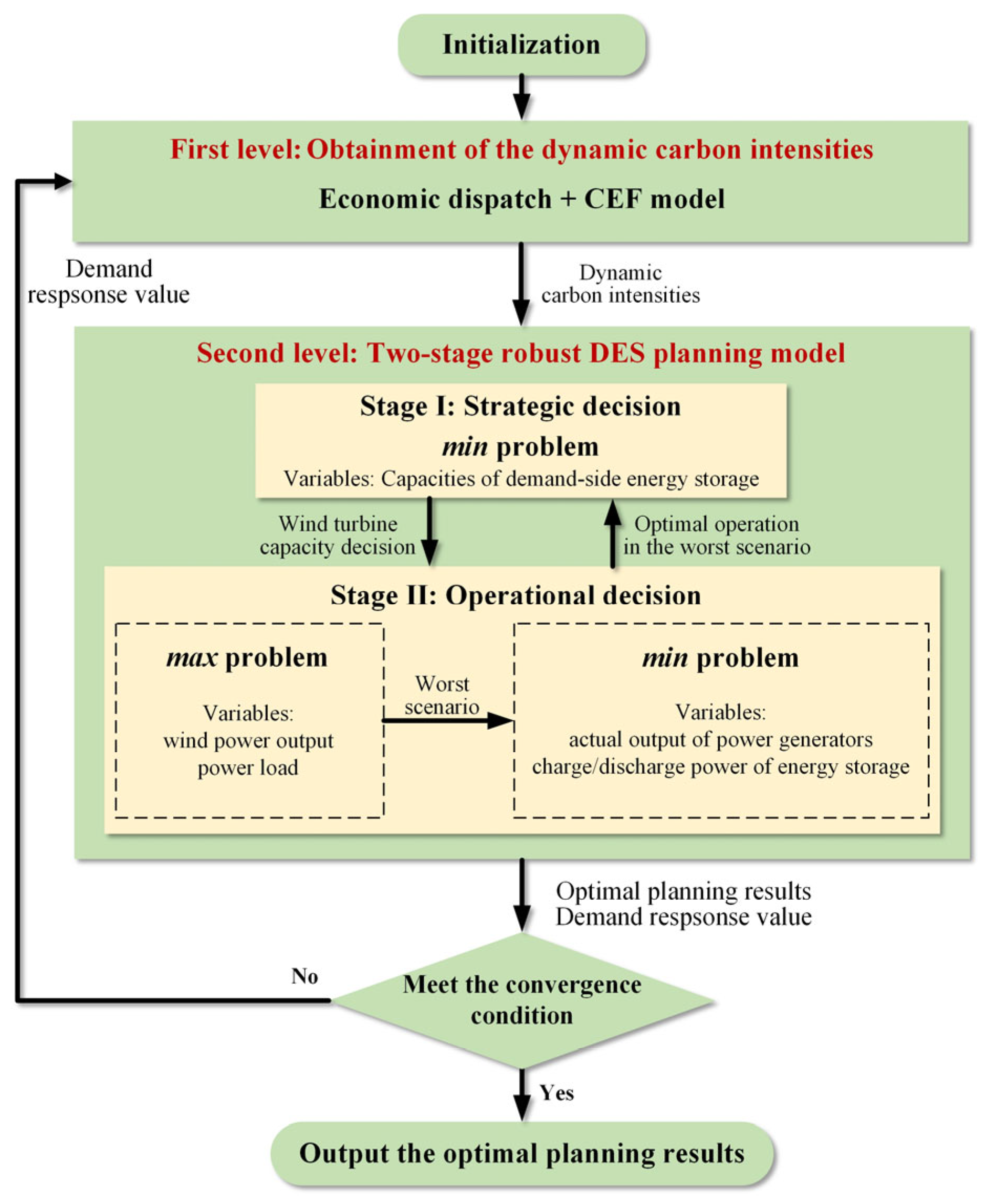
The framework diagram of the hierarchical two-stage robust DES planning model proposed in this paper is shown in Figure 1. At the first level, the dynamic carbon intensities are obtained based on the economic dispatch and CEF theory. At the second level, a two-stage robust planning model is adopted to optimize the capacities of demand-side energy storage. The planning results will be output if the convergence condition is met, or the optimal demand response results will be transferred to the first level and start the next loop.

3.1. The Two-Stage Robust Planning Model at the Second Level

3.1.1. Objective Function

The two-stage robust model consists of the strategic decision stage and the operational decision stage. The objective function of the strategic decision stage consists of the investment cost and the maintenance cost of the demand-side energy storage. Stage II is to obtain the optimal operational decision in the worst case of the uncertainty set. The objective function of Stage II consists of the power generation cost, demand-side electricity purchasing cost, and carbon incentive revenue as (5).
Min E N E S i Ω L c E S + c M T E N , i E S + max P ˜ j L , P ˜ i W min P g G , d i D R t = 1 T i Ω G c G P g , t G + j Ω L c t T O U P ˜ j , t L + d i , t D R C i , t C I
where c E S and c M T denote the DES investment cost coefficient and maintenance cost factors as (6) and (7); c G and c t T O U represent the power generation cost coefficient and time-of-use tariff, respectively; E N , i E S and P g , t G represent the rated capacity of the energy storage and the power generator output.
c E S = c E E S + c P E S / Γ N 365 × 24 N Y E S T 1 γ r e c
c M T = n = 1 N Y E S c Y M T 1 + i r 1 + d r n 365 × 24 N Y E S T
where c E E S and c P E S denote the investment cost factors of DES rated capacity and power; Γ N , γ r e c and N Y E S represent the energy storage duration, the recycling rate, and DES lifespan; c Y M T represents the annual maintenance cost factor; i r and d r denote the inflation rate and discount rate.

3.1.2. Constraints

The constraints of the robust model are shown below:
0 E N , i E S E ¯ N E S
P _ i G P i , t G P _ i G   i Ω G Ω W
0 P i , t G P ˜ i , t W   i Ω W
P i j , t = θ i j , t x i j
P _ i j P i j , t P ¯ i j
P i , t G = j Ω i P i j , t + P ˜ i , t L + d i , t D R
θ _ i j θ i j , t θ ¯ i j
θ r e f , t = 0
E i , t + 1 = 1 γ l o s s E i , t + η c h a P i , t c h a P i , t d i s / η d i s · Δ t
E i , 0 = E i , T
α m i n E N , i E S E i , t α m a x E N , i E S
0 P i , t c h a b i , t c h a P N , i E S ,   b i , t c h a 0 , 1
0 P i , t d i s b i , t d i s P N , i E S ,   b i , t d i s 0 , 1
b i , t c h a + b i , t d i s = 1
E N , i E S = Γ N P N , i E S
d i , t D R = P i , t d i s P i , t c h a
α m i n D R P ˜ i , t L d i , t D R α m a x D R P ˜ i , t L
F o r m u l a s   3 ~ 4
where parameters with top or bottom lines indicate the upper or lower bounds of the corresponding variables. Specifically, formula (8) denotes the constraint of rated energy storage capacities. Formulas (9)–(15) are operational limits of the power system; θ i j , t , x i j , and P i j , t represent the angle phase difference, the reactance and the power flow of the branch i j . Formulas (16)–(22) are constraints on DES operation; E i , t , P N , i E S , α m a x , and α m i n denote the state-of-charge (SOC), rated power, and upper and lower SOC limit rates of the energy storage, respectively. Formulas (23)–(24) represent the demand response constraints. Formula (25) denotes the constraints of the wind power and load uncertainty sets.

3.2. Solution Procedure Based on the N-C&CG Algorithm

The proposed two-stage robust DES planning model is an NP-hard problem, which cannot be solved directly by the commercial solver. According to the C&CG algorithm proposed in [35], the two-stage robust optimization can be divided into the master problem (MP) and subproblem (SP). The MP is a MILP problem and SP is a bi-level LP that can be directly calculated by solvers after being transformed by the KKT conditions. However, in the proposed two-stage robust planning model, binary variables are introduced to the SP by formulas (19) and (20), which resulted in the KKT condition not being applicable. Therefore, an N-C&CG algorithm proposed in [36] is adopted in this paper to handle this problem. According to the N-C&CG algorithm, the proposed two-stage robust planning model as (5)–(25) can be decomposed into the MP, the master problem of SP (MPS), and the subproblem of the SP (SPS) as (26)–(28). Specifically, MP and SPS are MILP problems and MPS is a max-min bi-level LP, which can be transformed into a single-level max MILP problem.
s . t . M P   min   X a T X + η A X d η b T Y r B 1 X + C 1 Y r + D 1 Z r + E 1 u r e B 2 X + C 2 Y r + D 2 Z r + E 2 u r = f
s . t . M P S   max   u τ τ b T Y v B 1 X + C 1 Y v + D 1 Z v + E 1 u v e B 2 X + C 2 Y v + D 2 Z v + E 2 u v = f b + C 1 T π v + E 1 T π v + C 2 T μ v + E 2 T μ v = 0 π v B 1 X + C 1 Y v + D 1 Z v + E 1 u v e = 0 π v 0
S P S   min   Y , Z b T Y v s . t .   B 1 X + C 1 Y v + D 1 Z v + E 1 u v e B 2 X + C 2 Y v + D 2 Z v + E 2 u v = f
where a and b are factor matrixes of the objective function in MP and SPS; B 1 ,   C 1 ,   D 1 ,   E 1 and B 2 ,   C 2 ,   D 2 ,   E 2 denote the factor matrixes of inequality constraints and equality constraints, respectively; e and f denote the constant matrixes of inequality constraints and equality constraints; π v and μ v are the dual variable matrixes; X denotes the decision variables in the MP, i.e., the DES capacities; Y r denotes the decision variables in the SPS of r loop, i.e., the power generator outputs, angle phase and SOC; Z denotes the matrix of binary variables introduced by constraints (19) and (20); u r denotes the uncertain variables, i.e., the wind power outputs and power loads. The superscript “ ” denotes that the value is given artificially or obtained from the previous process.
In summary, the detailed solving process of the proposed hierarchical two-stage robust energy storage planning model is elaborated as follows:
First level: Obtainment of the dynamic carbon intensities
Step 1Set the loop index and refresh the demand response value.
u = 1 ,   d i , t D R u = d i , t D R u 1 , d i , t D R 0 = 0
Step 2Carry out the economic dispatch, obtain the dynamic carbon intensities based on the CEF model as (1)–(6), and refresh e i , t B u in the coefficient matrix a .
e i , t B u = e i , t B
Step 3If u > 1 , determine whether the convergence condition is met:
(1)
If X u X u 1 < γ ( γ is the convergence threshold), terminate the solution process, output the final planning result X  =  X u .
(2)
If X u X u 1 γ , u = u + 1 , continue Step 1 in the outer loop of the second level.
Second level: Two-stage robust energy storage planning model
Outer loop: Solution of the MP
Step 1Initialize the loop parameters and initial values of uncertain variables:
r = 1 , U B o u t = + , L B o u t = + ,   u r = u 0
Step 2Solve the MP, get the DES capacities X r = X , and refresh L B o u t = m a x L B o u t , a T X * + η .
Step 3Skip to Step 1 in the inner loop, refresh u r  =  u v .
Step 4Determine whether the convergence condition is met:
(1)
If 1 L B o u t / U B o u t < ε ( ε is the convergence threshold), terminate the second level, output the planning result X u = X r and d i , t D R u = d i , t D R r to the first level.
(2)
If 1 L B o u t / U B o u t ε , r = r + 1 , back to Step 2 in the outer loop and add the following constraints to MP.
η b T Y r B 1 X + C 1 Y r + D 1 Z r + E 1 u r e B 2 X + C 2 Y r + D 2 Z r + E 2 u r = f
(29)
Inner loop: Solve the SP
Step 1Initialize the loop parameters and obtain initial values of binary variables:
v = 1 , U B i n = + , L B i n = + ,   Z v = Z r
Step 2Solve the MPS, refresh u v = u v and U B i n = m i n U B i n , τ .
Step 3Solve the SPS, refresh Z v = Z v and L B i n = m a x L B i n , b T Y v .
Step 4Determine whether the convergence condition is met:
(1)
If 1 L B i n / U B i n < ε , terminate the inner loop, return u r = u v and U B o u t = U B i n to the outer loop.
(2)
If 1 L B i n / U B i n ε , v = v + 1 , and Z v = Z v 1 , back to Step 2 in the inner loop, and add the following constraints to MPS.
τ b T Y v B 1 X + C 1 Y v + D 1 Z v + E 1 u v e B 2 X + C 2 Y v + D 2 Z v + E 2 u v = f b + C 1 T π v + E 1 T π v + C 2 T μ v + E 2 T μ v = 0 π v B 1 X + C 1 Y v + D 1 Z v + E 1 u v e = 0 π v 0
(30)

4. Case Results and Discussion

In this part, the validity and advantages of the proposed model were discussed. The model was tested on a modified IEEE 24-bus power system in the MATLAB/YALMIP simulation environment on a computer with an Intel Core i7-8700 processor and 32 GB RAM, and the optimal results were obtained by calling Gurobi commercial solver.

4.1. System Parameters

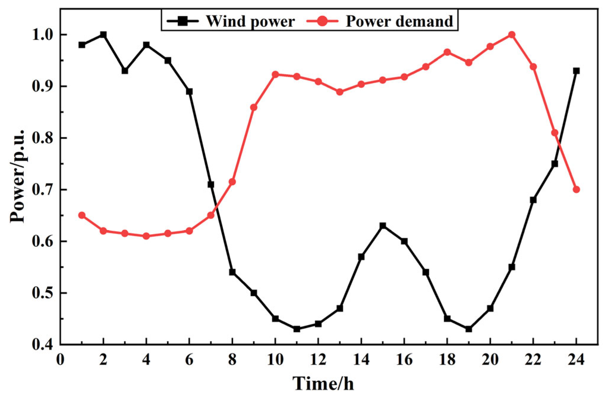
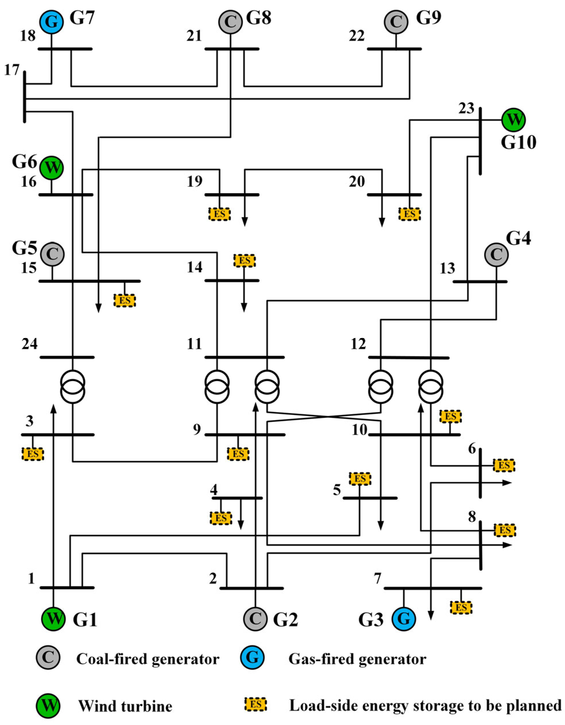
The power system with the demand-side energy storage to be planned is shown in Figure 2 [37]. The power system consists of five coal-fired generators, two gas-fired generators, and three wind turbines. The detailed parameters of the generators are listed in Table 1 [37,38]. Reference values of 12 loads in the power system are shown in Table 2. The typical 24-h curves of the power load and wind power maximum output used to generate uncertainty sets are shown in Figure 3. The uncertainty parameters of wind power and power loads are shown in Table 3. The detailed parameters of the energy storage are shown in Table 4 [39,40,41]. The time-of-use tariff is shown in Table 5. The carbon price of the proposed DCIM is set to 40 $/tCO2.

4.2. Optimization Results and Discussion

The convergence gap for the solution procedure of the model is the percentage change in demand-side energy storage capacity obtained in two adjacent MP. The convergence threshold in the model is 0.1%. The convergence is demonstrated in Figure 4. The model converges after 12 iterations.
To study the validity of the proposed model, two cases are set up below for comparison. Case 0 is the normal group without the proposed DCIM. Case 1 is the proposed model with the DCIM.
  • Case 0: The hierarchical two-stage robust DES planning model without the incentive mechanism.
  • Case 1: The hierarchical two-stage robust DES planning model with the proposed DCIM.
The optimal results of Cases 0 and 1 are shown in Table 6. Case 0 has no incentives and demand-side energy storage is not configured. The total configured DES capacity in Case 1 is 2863.6 MWh. The system in Case 1 reduced carbon emissions by 8.44% after planning compared to pre-planning. Therefore, it shows that the proposed DCIM can stimulate the system demand-side energy storage configuration and thus reduce the system’s carbon emissions.
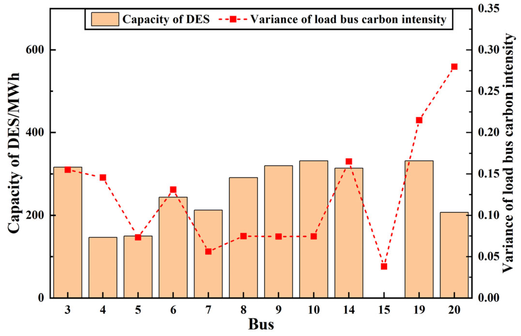
Figure 5 presents the results of demand-side energy storage planning for all load buses in Case 1 and the variance of carbon intensity fluctuations at load buses. Under the proposed DCIM, demand-side energy storage can be profitable by charging and discharging in an environment of fluctuating carbon intensity. When the carbon intensity is high, energy storage is discharged to reduce the demand for high-carbon-intensity electricity. When the carbon intensity is low, the energy storage is charged to promote wind power accommodation. Therefore, it is more favorable for energy storage to be configured on buses where the carbon intensity fluctuates more intensely. When the carbon intensity fluctuates relatively smoothly, it becomes difficult to profit from the configuration of the DES. As there is a coal-fired unit on bus 15, it can be noted from Figure 5 that bus 15 has the smallest carbon intensity variance, which results in insufficient DES planning incentives on bus 15. Since the carbon intensity variances of other load buses reach a certain threshold, DES can all be effectively configured. However, from Figure 5, we can notice no strong correlation between the value of the carbon intensity variance at the load bus and the DES planning capacity. This is because the DES planning capacity depends mainly on the load power values. Comparing the load power size in Table 2 with the demand-side energy storage planning capacity size in Figure 5, it is obvious that there exists a strong correlation between the two. Therefore, the bus carbon intensity variance, i.e., the degree of bus carbon intensity fluctuation, is the threshold of whether demand-side energy storage is suitable for planning. In contrast, the planning capacity of demand-side energy storage mainly depends on the load size.
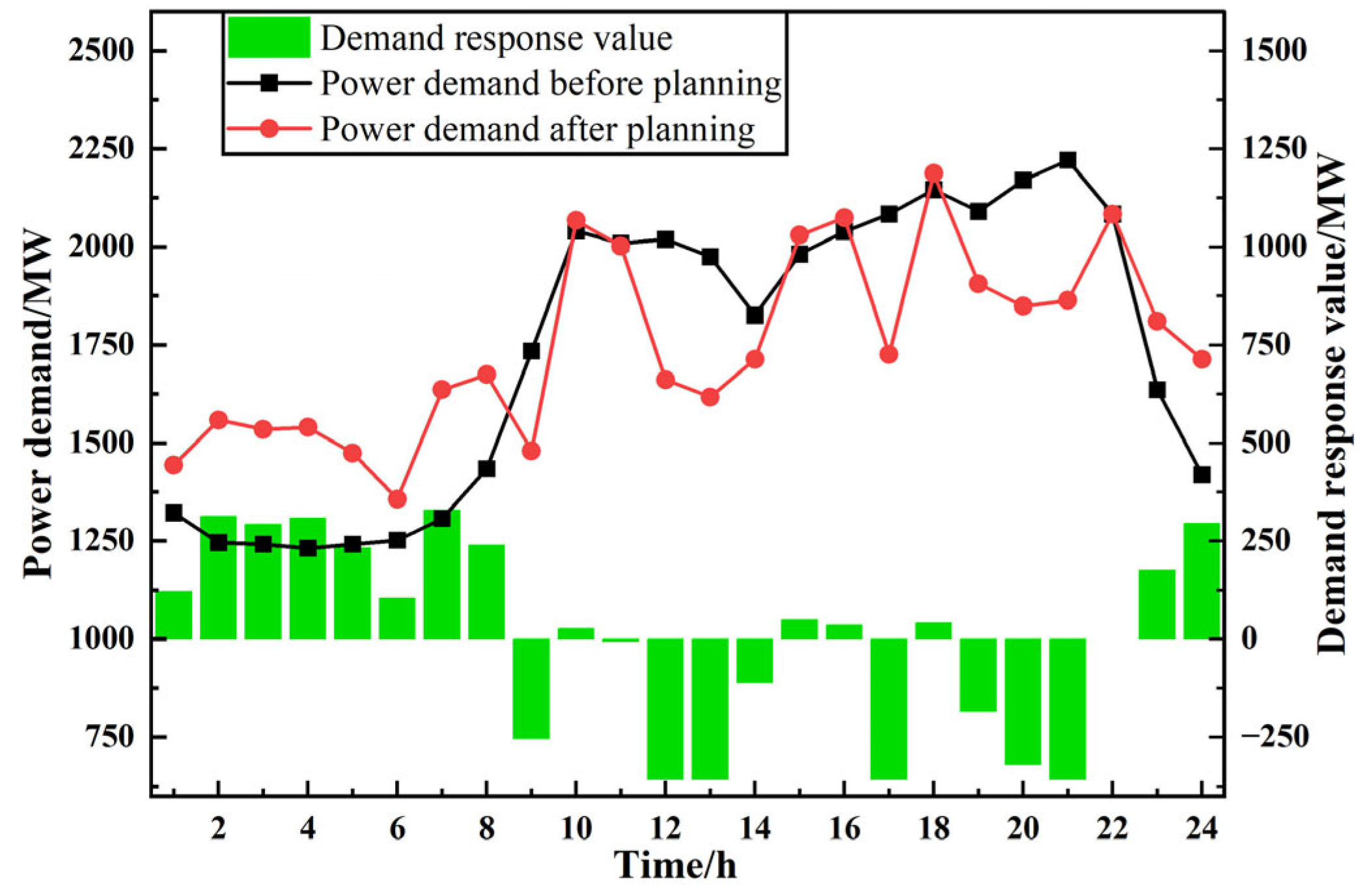
Figure 6 shows the demand response values and the power demand before and after planning. Figure 6 illustrates that the proposed DCIM facilitates load shaving and valley filling. Demand-side energy storage is charged at night to accommodate excess wind power in the system, and it is discharged during the day to reduce the use of high-carbon-intensity power. Thus, the overall carbon emission of the system decreases.
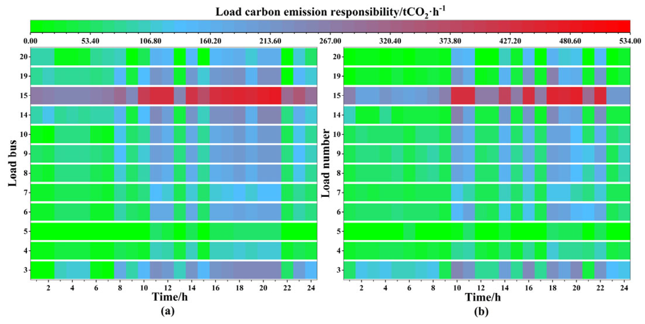
The 24-h load carbon emission responsibility map of Cases 0 and 1 are shown in Figure 7. It is obvious from Figure 7 that the overall responsibility of load carbon emissions in Case 1 is smaller than in Case 0, especially during the daytime. This is because the planned energy storage discharges the stored low-carbon power during high-carbon intensity, as described above. Therefore, demand-side energy storage planned under the proposed DCIM can facilitate the accommodation of wind power and carbon reduction.

4.3. Comparison and Discussion of Different Incentive Mechanisms

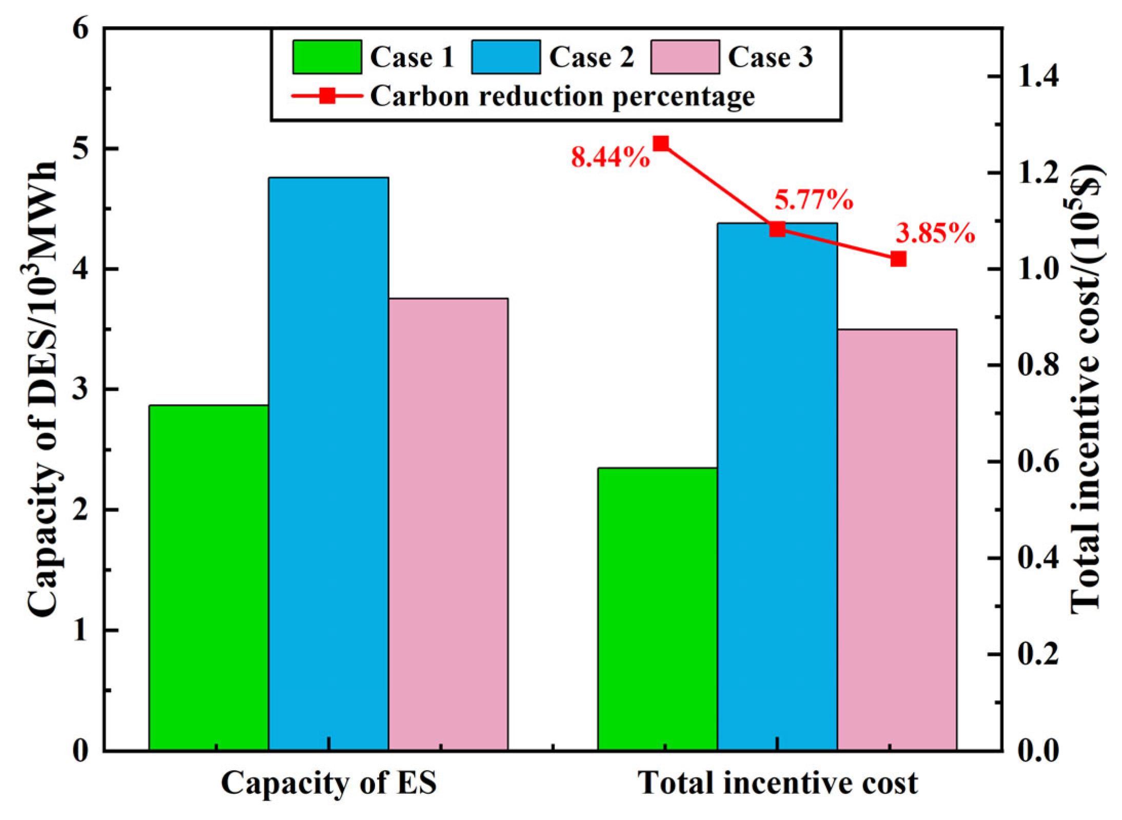
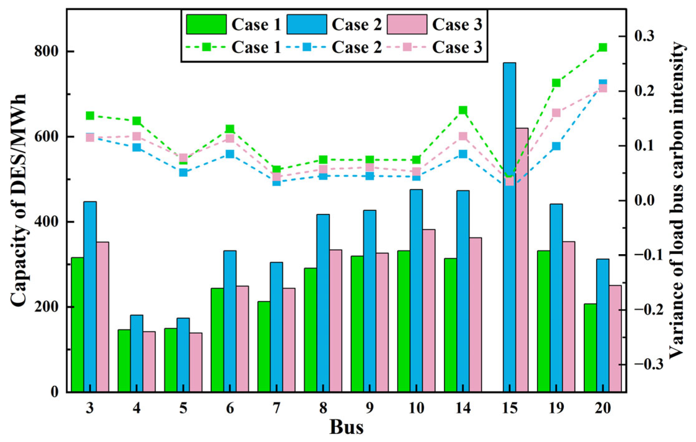
To verify the advantages of the proposed model, the proposed DCIM is compared with two other mechanisms commonly used in practice. Case 1 adopts the proposed DCIM based on the CEF theory. Both Case 2 and Case 3 incentivize energy storage planning from an energy perspective, using the capacity subsidy incentive mechanism and discharge subsidy incentive mechanism, respectively. The actual subsidy prices in Cases 2 and 3 are 23 $/MWh and 20 $/MWh, respectively.
  • Case 1: The hierarchical two-stage robust DES planning model with the proposed DCIM.
  • Case 2: The hierarchical two-stage robust DES planning model with capacity subsidy incentive mechanism.
  • Case 3: The hierarchical two-stage robust DES planning model with discharge subsidy incentive mechanism.
The total configured capacity and system carbon reduction rate of demand-side energy storage in three cases are shown in Figure 8. It can be found that optimization results in Case 1 have the least total configured DES capacity and the least incentive subsidy cost, yet the best carbon reduction effect. Therefore, it can be proved that compared with the other two mechanisms, the proposed DCIM can effectively lead the low-carbon oriented DES configuration and operation.
Figure 9 displays the planned capacities of DES and variances of carbon intensity fluctuations for load buses in the three cases. The essence of DES carbon reduction comes from the time shift of the power demand. Therefore the carbon reduction effect will be better if the load carbon intensities fluctuate sharply. It can be found in Figure 9 that the variance of carbon intensities at bus 15 is the least. The DES in Case 1 is not configured at bus 15, which differs from the results in Cases 2 and 3. Comparative analysis reveals that the proposed DCIM can effectively guide the carbon-oriented DES configuration and avoid the DES configuration in some specific buses which is weak for carbon reduction. In addition, the DES capacity configured at each load bus in Case 1 is almost the least among the three cases, but the carbon reduction effect of Case 1 is the best. These highlight the advantages of the proposed DCIM based directly on a carbon perspective.
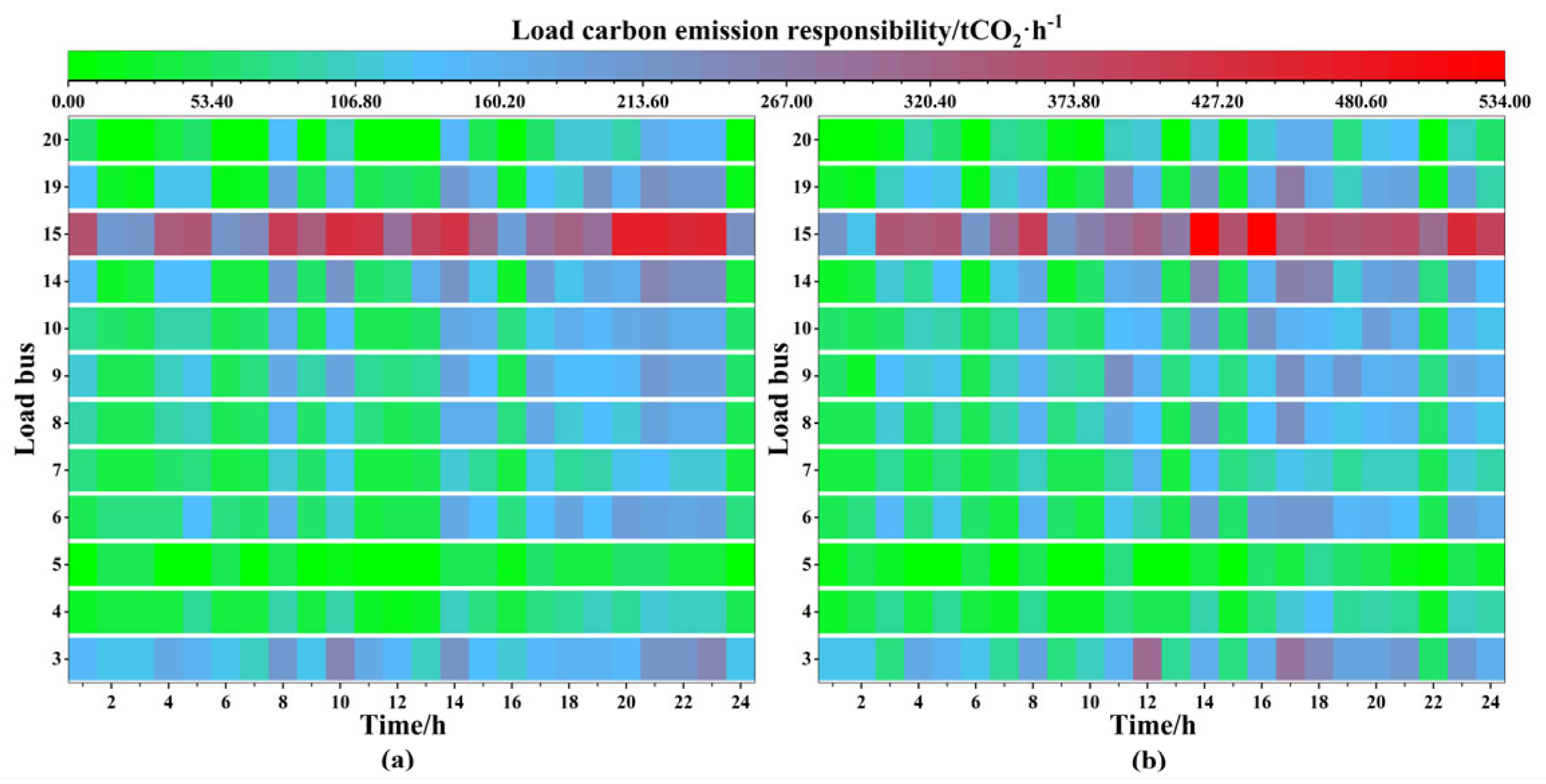
The 24-h load carbon emission responsibilities in Cases 2 and 3 are shown in Figure 10. Compared with Figure 7, it is clear that the load carbon emission responsibilities in Cases 2 and 3 are overall lower than the system carbon emission in Case 0, but in same periods, the load carbon emission responsibilities in Cases 2 and 3 are significantly increased instead. Case 1 shows a significant reduction in load carbon emission responsibilities compared to Cases 2 and 3. The comparison result proves that the proposed DCIM can efficaciously lead the low-carbon oriented DES configuration and operation and carbon emission reduction.

5. Conclusions

In this article, A DCIM is proposed based on the CEF theory. Besides, a hierarchical two-stage robust DES planning model incorporating the proposed DCIM is developed. The effectiveness and advantages of the proposed model are evaluated with the MATLAB/YALMIP platform on IEEE 24-bus power systems. From the case studies and discussion, we can draw the following points.
(1)
The proposed model can effectively promote carbon-oriented demand-side energy storage planning and reduce system carbon emissions by 8.44%.
(2)
The proposed DCIM can efficaciously lead the DES configuration and operation in a direction conducive to system carbon reduction.
(3)
By comparing with the other two existing incentive mechanisms, the proposed DCIM is more capable of promoting the system to reduce carbon emissions with less subsidy cost and energy storage investment cost.
This study mainly focuses on DES planning. Other load-side flexible resources, such as load shedding, electric vehicles, etc., were not considered in this study. Demand-side carbon policies to guide the orderly charging of electric vehicles can be further investigated in future research.
Author Contributions

Conceptualization, J.F., J.N. and H.Z.; methodology, J.F. and J.N.; software, J.F. and J.N.; validation, K.S., X.D. and L.G.; formal analysis, J.F., J.N. and H.Z.; investigation, X.D. and L.G.; resources, K.S. and H.Z.; data curation, J.F. and J.N.; writing—original draft preparation, J.F., J.N. and H.Z.; writing—review and editing, K.S., X.D. and L.G.; visualization, J.F. and J.N.; supervision, H.Z.; project administration, K.S. and H.Z. All authors have read and agreed to the published version of the manuscript.

Funding

This research received no external funding.

Institutional Review Board Statement

Not applicable.

Informed Consent Statement

Not applicable.

Data Availability Statement

The data presented in this study are available in this article.

Conflicts of Interest

The authors declare no conflict of interest.

References

  1. Meinshausen, M.; Lewis, J.; McGlade, C.; Gutschow, J.; Nicholls, Z.; Burdon, R.; Cozzi, L.; Hackmann, B. Realization of Paris Agreement pledges may limit warming just below 2 degrees C. Nature 2022, 604, 304–309. [Google Scholar] [CrossRef] [PubMed]
  2. Liu, Y.; Du, M.; Cui, Q.; Lin, J.; Liu, Y.; Liu, Q.; Tong, D.; Feng, K.; Hubacek, K. Contrasting suitability and ambition in regional carbon mitigation. Nat. Commun. 2022, 13, 4077. [Google Scholar] [CrossRef]
  3. Höhne, N.; Gidden, M.J.; den Elzen, M.; Hans, F.; Fyson, C.; Geiges, A.; Jeffery, M.L.; Gonzales-Zuñiga, S.; Mooldijk, S.; Hare, W.; et al. Wave of net zero emission targets opens window to meeting the Paris Agreement. Nat. Clim. Chang. 2021, 11, 820–822. [Google Scholar] [CrossRef]
  4. Mostafaeipour, A.; Bidokhti, A.; Fakhrzad, M.-B.; Sadegheih, A.; Zare Mehrjerdi, Y. A new model for the use of renewable electricity to reduce carbon dioxide emissions. Energy 2022, 238, 121602. [Google Scholar] [CrossRef]
  5. Jurasz, J.; Canales, F.A.; Kies, A.; Guezgouz, M.; Beluco, A. A review on the complementarity of renewable energy sources: Concept, metrics, application and future research directions. Sol. Energy 2020, 195, 703–724. [Google Scholar] [CrossRef]
  6. Kang, J.-N.; Wei, Y.-M.; Liu, L.-C.; Han, R.; Yu, B.-Y.; Wang, J.-W. Energy systems for climate change mitigation: A systematic review. Appl. Energy 2020, 263, 114602. [Google Scholar] [CrossRef]
  7. Zhang, Z.; Ding, T.; Zhou, Q.; Sun, Y.; Qu, M.; Zeng, Z.; Ju, Y.; Li, L.; Wang, K.; Chi, F. A review of technologies and applications on versatile energy storage systems. Renew. Sustain. Energy Rev. 2021, 148, 111263. [Google Scholar] [CrossRef]
  8. Impram, S.; Varbak Nese, S.; Oral, B. Challenges of renewable energy penetration on power system flexibility: A survey. Energy Strategy Rev. 2020, 31, 100539. [Google Scholar] [CrossRef]
  9. Sepulveda, N.A.; Jenkins, J.D.; Edington, A.; Mallapragada, D.S.; Lester, R.K. The design space for long-duration energy storage in decarbonized power systems. Nat. Energy 2021, 6, 506–516. [Google Scholar] [CrossRef]
  10. Ahmed, S.D.; Al-Ismail, F.S.M.; Shafiullah, M.; Al-Sulaiman, F.A.; El-Amin, I.M. Grid Integration Challenges of Wind Energy: A Review. IEEE Access 2020, 8, 10857–10878. [Google Scholar] [CrossRef]
  11. Xu, X.; Niu, D.; Xiao, B.; Guo, X.; Zhang, L.; Wang, K. Policy analysis for grid parity of wind power generation in China. Energy Policy 2020, 138, 111225. [Google Scholar] [CrossRef]
  12. Zakaria, A.; Ismail, F.B.; Lipu, M.S.H.; Hannan, M.A. Uncertainty models for stochastic optimization in renewable energy applications. Renew. Energy 2020, 145, 1543–1571. [Google Scholar] [CrossRef]
  13. Basit, M.A.; Dilshad, S.; Badar, R.; Sami ur Rehman, S.M. Limitations, challenges, and solution approaches in grid-connected renewable energy systems. Int. J. Energy Res. 2020, 44, 4132–4162. [Google Scholar] [CrossRef]
  14. Hou, H.; Xu, T.; Wu, X.; Wang, H.; Tang, A.; Chen, Y. Optimal capacity configuration of the wind-photovoltaic-storage hybrid power system based on gravity energy storage system. Appl. Energy 2020, 271, 115052. [Google Scholar] [CrossRef]
  15. Palys, M.J.; Daoutidis, P. Using hydrogen and ammonia for renewable energy storage: A geographically comprehensive techno-economic study. Comput. Chem. Eng. 2020, 136, 106785. [Google Scholar] [CrossRef]
  16. Zhang, C.; Cheng, H.; Liu, L.; Zhang, H.; Zhang, X.; Li, G. Coordination planning of wind farm, energy storage and transmission network with high-penetration renewable energy. Int. J. Electr. Power Energy Syst. 2020, 120, 105944. [Google Scholar] [CrossRef]
  17. Chen, Y.; Wei, W.; Wang, C.; Shafie-khah, M.; Catalao, J.P.S. Storage and Transmission Capacity Requirements of a Remote Solar Power Generation System. IEEE Syst. J. 2022, 16, 3175–3178. [Google Scholar] [CrossRef]
  18. Al-Ghussain, L.; Darwish Ahmad, A.; Abubaker, A.M.; Hassan, M.A. Techno-economic feasibility of thermal storage systems for the transition to 100% renewable grids. Renew. Energy 2022, 189, 800–812. [Google Scholar] [CrossRef]
  19. Wang, C.; Lin, X.; Nan, J.; Feng, J.; Zhou, W.; Zhou, H. Coordinating thermal energy storage capacity planning and multi-channels energy dispatch in wind-concentrating solar power energy system. J. Clean. Prod. 2022, 350, 131405. [Google Scholar] [CrossRef]
  20. Chen, S.; Li, Z.; Li, W. Integrating high share of renewable energy into power system using customer-sited energy storage. Renew. Sustain. Energy Rev. 2021, 143, 110893. [Google Scholar] [CrossRef]
  21. Wang, Y.; Song, F.; Ma, Y.; Zhang, Y.; Yang, J.; Liu, Y.; Zhang, F.; Zhu, J. Research on capacity planning and optimization of regional integrated energy system based on hybrid energy storage system. Appl. Therm. Eng. 2020, 180, 115834. [Google Scholar] [CrossRef]
  22. Shen, Y.; Hu, W.; Liu, M.; Yang, F.; Kong, X. Energy storage optimization method for microgrid considering multi-energy coupling demand response. J. Energy Storage 2022, 45, 103521. [Google Scholar] [CrossRef]
  23. Huang, Q.; Xu, Y.; Courcoubetis, C. Financial Incentives for Joint Storage Planning and Operation in Energy and Regulation Markets. IEEE Trans. Power Syst. 2019, 34, 3326–3339. [Google Scholar] [CrossRef]
  24. Tian, K.; Sun, W.; Han, D.; Yang, C. Joint Planning and Operation for Renewable- Storage Under Different Financial Incentives and Market Mechanisms. IEEE Access. 2020, 8, 13998–14012. [Google Scholar] [CrossRef]
  25. Wang, C.; Zhang, Z.; Qiao, J. Risk-Constrained Optimal Operation Strategy for Virtual Power Plants Considering Incentive-Based Demand Response. In Proceedings of the 2022 IEEE/IAS Industrial and Commercial Power System Asia (I&CPS Asia), Shanghai, China, 8–11 July 2022; pp. 1094–1101. [Google Scholar]
  26. Wang, J.; Zhong, H.; Wu, C.; Du, E.; Xia, Q.; Kang, C. Incentivizing distributed energy resource aggregation in energy and capacity markets: An energy sharing scheme and mechanism design. Appl. Energy 2019, 252, 113471. [Google Scholar] [CrossRef]
  27. Zhou, T.; Kang, C.; Xu, Q.; Chen, Q. Preliminary theoretical investigation on power system carbon emission flow. Autom. Electr. Power Syst. 2012, 36, 38. [Google Scholar]
  28. Kang, C.; Zhou, T.; Chen, Q.; Wang, J.; Sun, Y.; Xia, Q.; Yan, H. Carbon emission flow from generation to demand: A network-based model. IEEE Trans. Smart Grid 2015, 6, 2386–2394. [Google Scholar] [CrossRef]
  29. Wang, Y.; Qiu, J.; Tao, Y. Optimal Power Scheduling Using Data-Driven Carbon Emission Flow Modelling for Carbon Intensity Control. IEEE Trans. Power Syst. 2022, 37, 2894–2905. [Google Scholar] [CrossRef]
  30. Wang, Y.; Qiu, J.; Tao, Y.; Zhao, J. Carbon-Oriented Operational Planning in Coupled Electricity and Emission Trading Markets. IEEE Trans. Power Syst. 2020, 35, 3145–3157. [Google Scholar] [CrossRef]
  31. Wei, X.; Sun, Y.; Zhou, B.; Zhang, X.; Wang, G.; Qiu, J. Carbon emission flow oriented multitasking multi-objective optimization of electricity-hydrogen integrated energy system. IET Renew. Power Gener. 2022, 16, 1474–1489. [Google Scholar] [CrossRef]
  32. Cheng, Y.; Zhang, N.; Zhang, B.; Kang, C.; Xi, W.; Feng, M. Low-Carbon Operation of Multiple Energy Systems Based on Energy-Carbon Integrated Prices. IEEE Trans. Smart Grid 2020, 11, 1307–1318. [Google Scholar] [CrossRef]
  33. Chen, D. Study on Factor Decomposition and Network Flow Analysis of Carbon Emission in Power System; Zhejiang University: Hangzhou, China, 2016. [Google Scholar]
  34. Bialek, J. Tracing the Flow of Electricity. IEE Proc. Gener. Transm. Distrib. 1996, 143, 313–320. [Google Scholar] [CrossRef]
  35. Zeng, B.; Zhao, L. Solving two-stage robust optimization problems using a column-and-constraint generation method. Oper. Res. Lett. 2013, 41, 457–461. [Google Scholar] [CrossRef]
  36. Long, Z.; Bo, Z. An Exact Algorithm for Two-Stage Robust Optimization with Mixed Integer Recourse Problems; University of South Florida: Tampa, FL, USA, 2012. [Google Scholar]
  37. Zimmerman, R.D.; Murillo-Sanchez, C.E.; Thomas, R.J. MATPOWER: Steady-state operations, planning, and analysis tools for power systems research and education. IEEE Trans. Power Syst. 2011, 26, 12–19. [Google Scholar] [CrossRef]
  38. Jamie McIntyre, B.B.; Seto, H.; Borchardt, S. Comparison of Lifecycle Greenhouse Gas Emissions of Various Electricity Generation Sources; World Nuclear Association: London, UK, 2011. [Google Scholar]
  39. Ma, R.; Zhang, Q.; Wu, X.; Li, X. Random fuzzy uncertain model for daily wind speed. Proc. Chin. Soc. Electr. Eng. 2015, 35, 6351–6358. [Google Scholar]
  40. Chen, C.M.; Wu, X.Y.; Li, Y.; Zhu, X.J.; Li, Z.S.; Ma, J.E.; Qiu, W.Q.; Liu, C.; Lin, Z.Z.; Yang, L.; et al. Distributionally robust day-ahead scheduling of park-level integrated energy system considering generalized energy storages. Appl. Energy 2021, 302, 117493. [Google Scholar] [CrossRef]
  41. Shi, L.; Yang, F.; Liu, Y.; Wu, F. Multi-scenario user-side energy storage capacity optimization configuration considering social development. Power Syst. Prot. Control. 2021, 49, 59–66. [Google Scholar]
Figure 1. The framework diagram of the proposed hierarchical two-stage robust DES planning model.
Applsci 13 06524 g001
Figure 2. The revised IEEE 24-bus power system with the demand-side energy storage to be planned.
Applsci 13 06524 g002
Figure 3. Wind power and load curves for generating uncertainty sets.
Applsci 13 06524 g003
Figure 4. Convergence of the proposed hierarchical model.
Applsci 13 06524 g004
Figure 5. DES planned capacity and load bus carbon intensity fluctuation variance in Case 1.
Applsci 13 06524 g005
Figure 6. Demand response values and power demand before and after planning.
Applsci 13 06524 g006
Figure 7. (a) 24-h load carbon emission responsibility map in Case 0; (b) 24-h load carbon emission responsibility map in Case 1.
Applsci 13 06524 g007
Figure 8. Optimization results of the three cases.
Applsci 13 06524 g008
Figure 9. DES planned capacity and load bus carbon intensity fluctuation variance in three cases.
Applsci 13 06524 g009
Figure 10. (a) 24-h load carbon emission responsibility map in Case 2; (b) 24-h load carbon emission responsibility map in Case 3.
Applsci 13 06524 g010
Table 1. Generator parameters.
GeneratorTypeCapacity/(MW)Cost Factor/(USD/MWh)Carbon Intensity/(tCO2/MWh)
G1Wind turbine900100
G2Coal-fired350301.31
G3Gas-fired150620.564
G4Coal-fired750311.25
G5Coal-fired500301.31
G6Wind turbine900100
G7Gas-fired150620.564
G8Coal-fired600311.25
G9Coal-fired600301.31
G10Wind turbine900100
Table 2. Reference values of power loads.
LoadBusPower Demand/(MW)LoadBusPower Demand/(MW)
L13180L79175
L2474L810195
L3571L914194
L46136L1015317
L57125L1119181
L68171L1220128
Table 3. Uncertainty parameters.
ItemValueItemValue
Γ L 12 Δ P i , t L ± 20 %
Γ W 12//
Table 4. Energy storage parameters.
ItemValueItemValue
α m a x , α m i n 90%, 10% c E E S , c P E S 100 USD/kW, 250 USD/kWh
η c h a , η d i s 95%, 95% c Y M T 25 $/(kW∙Year)
N Y , D S B 8 Years i r , d r 2%, 10%
Γ N 8 α m i n D R , α m a x D R ±30%
Table 5. Time-of-use tariff parameters.
TimeElectricity Tariff/(USD/kWh)
0:00–8:000.036
8:00–22:000.110
22:00–24:000.036
Table 6. The optimal results of Case 0 and Case 1.
CaseDES Total Capacity/MWhSystem Carbon Reduction Rate/%
Case 000
Case 12863.68.44
Disclaimer/Publisher’s Note: The statements, opinions and data contained in all publications are solely those of the individual author(s) and contributor(s) and not of MDPI and/or the editor(s). MDPI and/or the editor(s) disclaim responsibility for any injury to people or property resulting from any ideas, methods, instructions or products referred to in the content.