1. Introduction
The Brazilian railroad transport system has received significant investments in recent years. In order to balance the Brazilian transport matrix, the rail system, which currently corresponds to 15% of the total transportation in the country, is intended to represent 30% of transported loads in the next 10 years. According to the Ministry of Infrastructure, this objective makes it possible to reduce the cost of transport, as well as to improve the logistical efficiency of Brazilian agribusiness [
1]. For this expansion to occur, Brazilian railroads are looking to increase the performance of their assets. Wheel/rail interfaces have great potential to improve the competitiveness of the railroad. In addition to reducing maintenance costs, the purpose of this work, the literature shows secondary gains with improvements in wheel/rail contact, such as reduced fuel consumption, reduced derailments, and increased mesh capacity. According to [
2], the wheel, as an important part of the freight rail car, directly affects the quality and safety of operations. For rolling stock, wheel consumption generally represents the highest maintenance cost and is among the highest total costs of a railroad. Therefore, the understanding of the variables that influence wear and, consequently, lead to reductions in the useful life of wheels, must be investigated. VLI Logística, one of the main Brazilian railroads, has developed technical studies for this purpose. The case study applied in this work will focus on the wear of wagon wheels in the Centro Norte corridor, 720 km long, which is characterized by a broad-gauge (1600 mm) railroad that is predominantly used for grain transport using hopper wagons. With such an extensive fleet, it is essential to use equipment along the track, known as waysides, to monitor the vehicle conditions and predictive maintenance [
3]. It is known that wheel wear is directly related to the bogie railway suspension. Therefore, correlations obtained through regression between data samples from the wheel monitoring system and the bogie, as well as the use of dynamic simulations, will allow for an analysis of wheel wear. Thus, it is possible to perform statistical modeling to identify the wear function and improve the maintenance strategy of the highest-cost component. In this work, the evaluated parameters were obtained through laser measurement systems known as wheel views, which measure the main wheel parameters. The useful life of a wheel corresponds to the total kilometers traveled until it is scrapped. At present, the average useful life of the wheels in the Centro Norte corridor is 0.8 million km, which is a low value compared to those for other railroad companies, with wheels of 1.7 million km [
4]. Therefore, it is necessary to develop strategies to increase wheel life and reduce maintenance costs. The failure mode of VLI wheels is due to flange wear, a condition in which the flange reaches the minimum safety limit of 21 mm. The wheel is then reprofiled on the lathe in a workshop to recompose the flange, leading to a reduction in the thickness of the rim. This cycle continues until the rim thickness is minimal and there is no more material to be removed. Therefore, the wheel life is determined by flange wear in conjunction with reprofiling practices, which implies three useful lives can be obtained. For the AAR-1B Narrow Flange profile used in the VLI, the flange initial thickness was 32 mm.
The most common wheel failure mode is flange wear [
5], which is a consequence of the friction between the wheel and the rail. To restore this flange, a substantial amount of metal is removed from the wheel rim. The wear can be explained by the wheel and rail contact theory. In the wheel–rail contact patch (Hertz ellipse), two main situations can occur: adhesion and slip [
6]. This creepage occurs due to the slipping velocity between the wheel and the rail at the wheel–rail contact patch. This creepage can be divided into three components: longitudinal, lateral, and spin. The longitudinal creepage occurs when the wheel does not cover its entire perimeter on the rail and is given as a percentage. The creep force is calculated by multiplying the normal force by the creepage. Thus, for positive longitudinal slip, with an increase in tension, the slip region increases and the non-slip region decreases, resulting in rolling and slipping contact. The traction–creep curve can be affected by the presence of a third body in the wheel–rail contact. This can be formed by a substance applied to increase or decrease friction (friction modifier or lubricant) or a natural substance acting to decrease friction (water, leaves, etc.) [
7]. Lateral slip occurs due to the existence of an angle of attack
: the angle between the track radial line and the center line of the wheelset axle. Wheel flange wear occurs due to slippage between the wheel–rail contacts. This interaction results in the loss of material from the solid. To correlate the creepage with mass loss and wear, Ref. [
7] performed an experiment known as twin disc. Two cylindrical samples, one extracted from the wheel and the other from the rail, were applied and placed in contact with each other with parallel axes. The tests were configured to represent a given pressure and percentage of longitudinal slip.
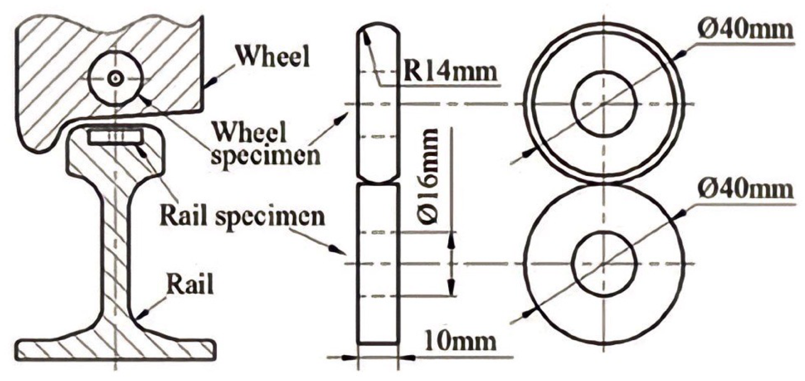
Figure 1 shows the test.
Figure 1 can be used to identify the sizes of specimens extracted from the wheel and rail for applications in the test. This test is recommended in the [
9] AAR M-107/M-208 standard as a requirement for class D wheel development. The creepages were represented in the form of a variable
, divided by the contact patch area.
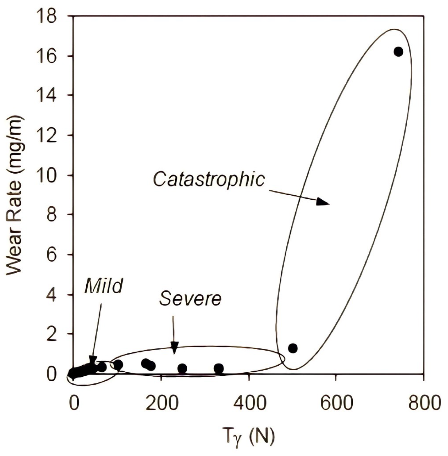
Figure 2 demonstrates the different behaviors obtained in the test, in which the function relating wear (loss of mass of specimens) to the indicator
is not linear. The behavior can be divided into three levels: medium, severe, and catastrophic [
10].
The bogies are directly related to wheel wear [
11]. Thus, understanding the vehicle’s dynamic behavior during wheel–rail contact, which determines wheel performance, is only possible when analyzed simultaneously with the performance of railway bogies. Brazilian freight railways adopted a three-piece bogie model containing two side frames and a bolster. Factors such as simplicity and low cost made bogie suspension, known as the three-piece bogie, the main choice for American freight railroads [
12]. In this type of bogie, the friction wedge is the main element used to dissipate the energy from vibration. This element provides dry friction damping between the friction wedge surface and the bogie side wear plate. The increase in wedge wear can reduce the damping. Therefore, the wedge height limit is defined through manual and rule standards. It is desirable for a bogie to allow for the wheelsets to steer effectively in curves and have an adequate amount of warp stiffness [
13]. Warp stiffness is the rotational stiffness that resists the moments generated by the suspension [
14]. An insufficient warp stiffness could lead the bogie to warp. This occurs when the side frame position forms a parallelogram. When a bogie is in warp, the wheelsets are both sharply misaligned with the turn rail at a severe angle of attack [
15].
New bogie designs according to [
16] AAR M-976 specifications should meet the following requirements: increase warp stiffness through improvements in friction wedges; use pads to allow a greater degree of freedom for the wheelsets to position themselves radially; and reduce the angle of attack and, consequently, rolling resistance [
17]. The increase in warp stiffness allowed for the use of pads due to the elastomeric elements not performing well in bogies without such features. In addition, the increase in warp resistance is directly related to the reduction in hunting [
18].
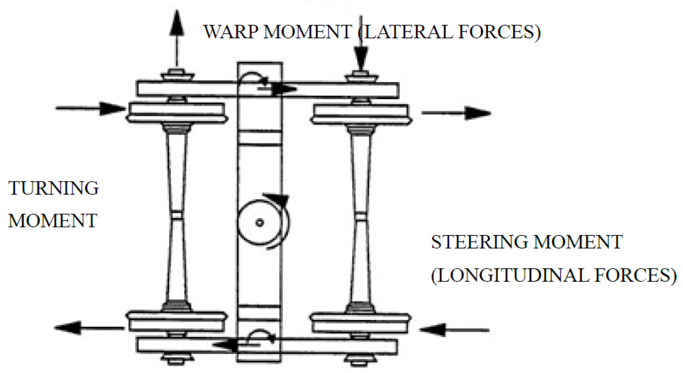
When the bogie steers in a curve, certain moments occur. The steering moment occurs when longitudinal forces developed at the wheelset conicity of wheels. The outer wheel side rolls on a larger radius than the inner side. The larger radius of the outer wheel creates a steering moment that pulls the wheelset on a curved path. This steering moment is generated by the differences in the radius of the outer and inner wheel [
6]. The warp moment is provided by lateral forces when the wheelset reaches the angle of attack. This undesirable angle occurs in bogies without pads, with medium curves, and with very sharp curves for bogies with a modern design. The turning moment is a resistance moment for the bogie turning under the carbody at the center bowl. This moment is a function of the steering moment of the wheelset and the warp movement of the bogie. A significant resistance to bolster rotation, or turning moment, is developed due to the friction in the centerbowl or rotational resistance due to tight side bearings [
15]. It is desirable to reduce the coefficient of friction between the bolster center plate and the carbody center bowl. Thus, a polymer can be applied.
Figure 3 shows the warp, turning, and steering moment acting on the bogie.
2. Methodology
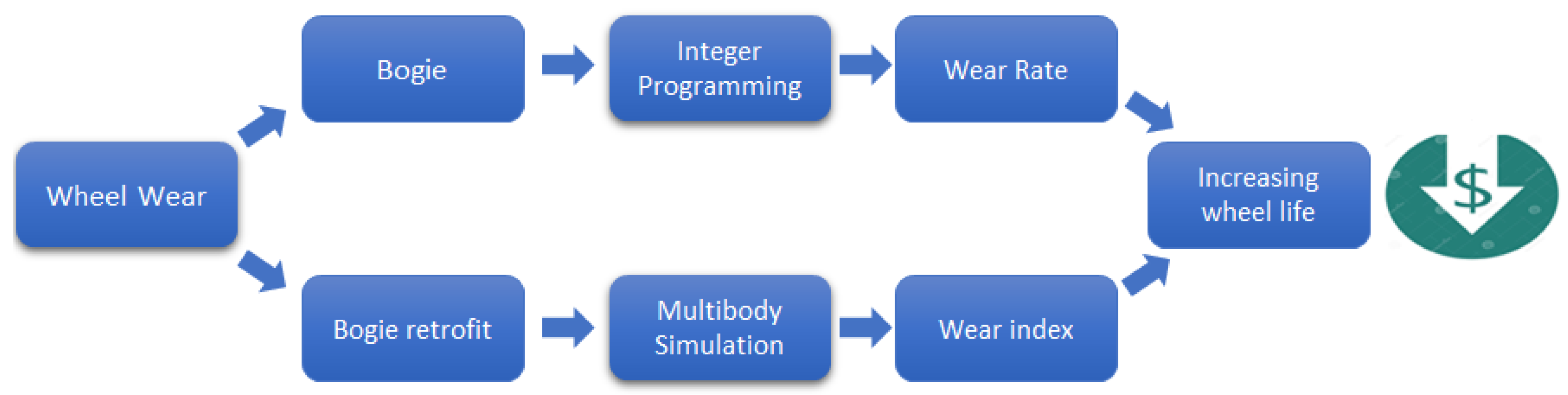
The methodology aims to identify the factors that influence wheel wear. Therefore, statistical and dynamic analyses were undertaken to understand the influence of bogie maintenance and retrofitting, respectively, on wheel wear. The bogie maintenance approach was used to analyze the measured data through waysides to monitor wheels and bogies. Then, an integer programming was modeled to identify the best bogie maintenance strategy to achieve a low wear rate using the new wedge parameters. The bogie retrofitting method contemplates the bogie dynamic analysis by modeling in the multibody system software VAMPIRE (VAMPIRE Pro 8.0). The retrofit consists of an evaluation of the feasibility of improving the ride control 6.1/2” × 12” bogie design with constant damping, as well as the gains in the wear index.
Figure 4 illustrates the two proposed approaches, which act in parallel to increase wheel life, bogie maintenance, and retrofitting, along with their respective modeling methods, which resulted in a final indicator correlated with wheel life.
2.1. Maintenance
Wheel wear rate was calculated using 150 rail cars as a sample. Wheel measurements were evaluated during the one-year period in which hopper cars ran at approximately 100,000 km. However, it should be noted that the travel distance used for the rate was the actual one for each car in the sample.
Wear Rate: wheel flange wear rate (mm/km);
: final flange thickness (mm);
: initial flange thickness (mm).
This approach considers the friction wedge to have a greater correlation with the bogie performance. Therefore, friction wedge height was used as a parameter to evaluate wheel wear behavior.
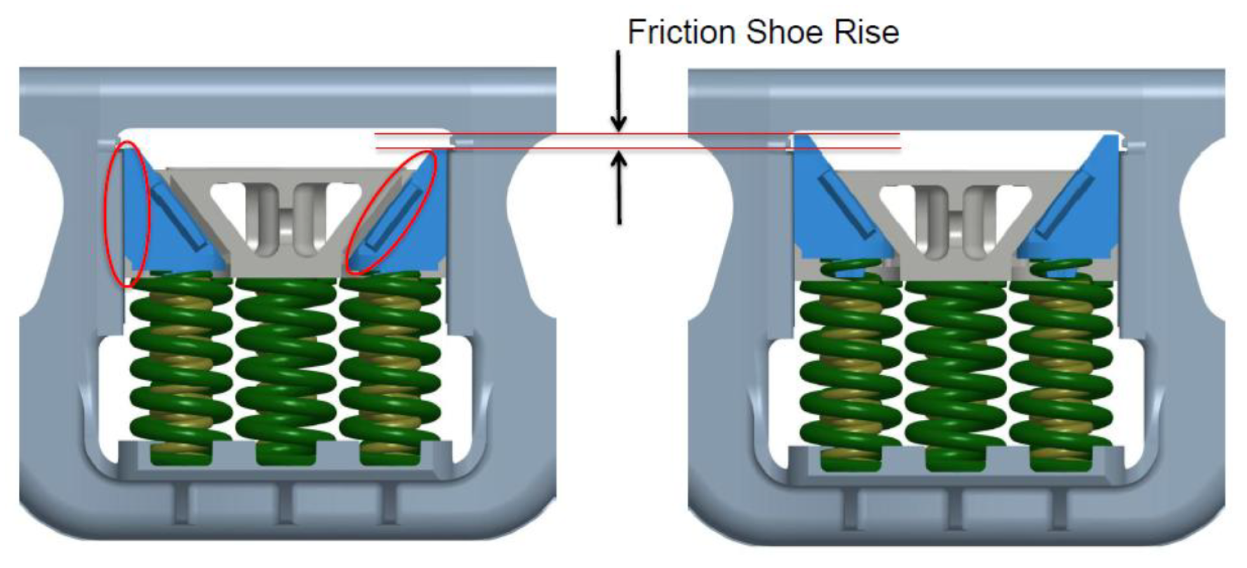
Figure 5 shows the increase in the friction wedge height.
VLI’s maintenance parameter limit was fixed in accordance with the [
16] AAR standard criteria. These criteria focus on railway safety and usually do not establish criteria for performance analysis. The model’s purpose was to define additional maintenance parameters for the hopper cars’ fleet, considering the maintenance costs for bogies and wheels, in addition to the cost of a new wheel. The mathematical model that was proposed to solve this problem is based on integer programming, as represented by expressions (1)–(7). Set V represents the wagons (index
i), and set N represents the years (index
j). The used parameters were the cost of bogie maintenance
, the cost of turning the wheels
, the cost of replacing a new wheel
, and
, the cost of doing nothing. In addition, the decision variables are binary, where
if bogie maintenance is performed on wagon
i in year
j and 0 otherwise;
if wagon wheel turning is performed in year
j and 0 otherwise;
if the wheel is replaced on wagon
i in year
j; and
if nothing is performed on wagon
i in year
j, and 0 otherwise. To project the flange thickness (f), the wear rates were parameterized as “taxam” and “taxaa”; these represent the wear rate of bogie maintenance at the current rate of the car. By design, the AAR-1B narrow flange thickness (fn) was 32 mm, and the limit (fl) was 21 mm, according to the VLI´s manual. The costs used in the modeling are defined below:
: cost of fixing the bogie (BRL 3175.00);
: turning cost (BRL 304.00);
: wheelset average unit price (BRL 7290.00);
: doing nothing (BRL 0.00).
Constraint (2) guarantees that the wheelset cannot be turned and replaced at the same time in the same year. Constraint (3) states that the wheel cannot be turned more than twice, since it is a wheel with three lives (including the initial one). Constraints (4) and (5) calculate the flange thickness, a result of the rate and strategies used, and compare this with the lower and upper limits. The first is based on operational safety, and the second is based on the maximum thickness for this wheel design. The variable “ratea” is the value of the regression rate. Analogously, the “taxam” is calculated and multiplied by the average total km traveled per year. For the post-maintenance condition of the bogie, the lowest regression rate is considered. The modeling performed in non-linear integer programming was parameterized within Excel for optimization to minimize costs. The binary multiplication variables in constraints (4) and (5) produced a non-linearity; the solution method used in the solver was the nonlinear GRG.
2.2. Retrofitting
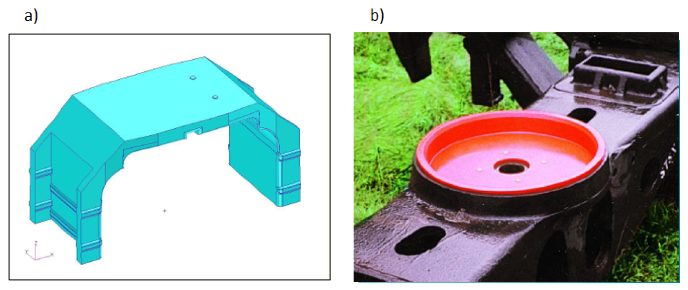
The proposed bogie retrofit aims to increase the steering moment and reduce the warp and turning moment with ride control 6.1/2” × 12”. The use of polymeric pads in the primary suspension, which reduce the rigidity between the adapter and the side frame pedestal compared to the friction caused by the wear plate, can improve wheelset steering. Hence, the polymer can reduce the angle of attack. Another polymer that was applied is the center bowl liner, which acts to decrease the turning moment in the secondary suspension. In addition, there is a reduction in the warp moment and, consequently, a reduction in the lateral forces, which increases the useful life of the bogie suspension components (friction wedges, wear plates, adapter, and springs) and the track (rail and fixing).
Polyurethane pads were chosen rather than rubber shear pads because the rubber pads should only be applied on the side frames with a stop, as this type of pad works by shearing. Thus, due to the absence of these stops on the side frame in the bogie’s fleet, this pad model was not considered for the retrofit. The polyurethane was built between the metallic adapter and the side frame pedestal. In addition, the application of these items helped to keep the bogie in a square after curves. The polyurethane pad’s mechanical properties were provided by the manufacturer Retesp, who supplies 6.1/2” × 12” wide pedestal pads. To establish their properties, nonlinear modeling was performed in the MSC Marc (Marc 2013) finite element software considering the pads’ nonlinear contact behavior with the adapter and pedestal. Due to these similarities, the same property values were used for the narrow pedestal polyurethane pad. The directions considered for the stiffness values were calculated at each of the six degrees of freedom. The pad stiffness matrix output was derived using finite element analysis. This matrix can be written as in Equation (
9) [
20] , and the parameters are shown in
Table 1.
The main parameters used to model HFT in VAMPIRE are summarized in
Table 1.
Equation (
10) shows the non-linear behavior due to the solid stop in the travel carried by the bumpstop element.
The applied polymers are shown in
Figure 6: (a) pads and (b) center bowl liner. The figure shows the model in finite element analysis that was developed to obtain the pad properties
To decrease the turning moment resistance and consequently improve the bogie steering in terms of curves, the use of polymeric discs to reduce friction was considered.
: turning moment;
: angular speed;
: coefficient of friction;
R: center plate radius.
Equation (
14) shows that the reduction in the coefficient of friction is directly related to the reduction in the resistance to the center plate rotation (turning moment). The center bowl liner polymers were modeled with the physical properties provided by Amsted Rail, which considered the coefficient of friction to be 0.15 [
22]. All the polymeric features were considered in the VAMPIRE model, which was modeled with 66 degrees of freedom. In the model, the masses were considered rigid bodies, which are considered appropriate in this approach. Depending on their aim, some studies considered flexible modes, such as a flexible carbody, to evaluate a yaw damper connected to these modes in the secondary suspension [
23] and a flexible wheelset to analyze coupled frequencies during rail corrugation due to wheel stick-slip [
24].
A modal analysis was performed to verify the computational model’s adherence to the real vehicle using the eigenvalue method.
The computational vehicle model was validated using real measures from the instrumented vehicle. The instrumentation consisted of accelerometers and a gyroscope applied to the center sill of the HFT, allowing for measurements of X, Y, and Z and rotations around these axes. The sensors were equipped with the GPS and had an acquisition rate of 400 Hz. Therefore, the roll and pitch frequencies from
Table 2 were compared with the collected data when the vehicle was run in track sections with cross-level and vertical irregularities, causing harmonic and transient base excitations, respectively. The harmonic excitation was the result of the 12.8 m cross-level wavelength while the vehicle was running at 30 km/h. The wavelength was calculated using Fourier transform. The vertical transient excitation was the result of the fouled ballast. The roll frequency calculated from the instrumentation was 0.64 Hz, and the pitch frequency was 1.69 Hz, resulting in an error of 9% and 3%, respectively, which is an acceptable difference considering that the vehicle was not fully loaded and the bogies were not new.
Figure 7 shows the roll signal measured on field.
Furthermore, when looking at
Table 2, it is possible to identify that the frequency values are as expected as the natural roll frequency has the lowest value among the main modes of vibration. In addition, the pitch and bounce vibration modes have close frequencies; that is, excitation frequencies close to the natural frequency of these modes will couple the movements so that they occur simultaneously.
Figure 8 illustrates the 3D model generated in AutoCAD Mechanical to obtain the carbody mass properties.
3. Results and Discussion
3.1. Bogie Maintenance Influence
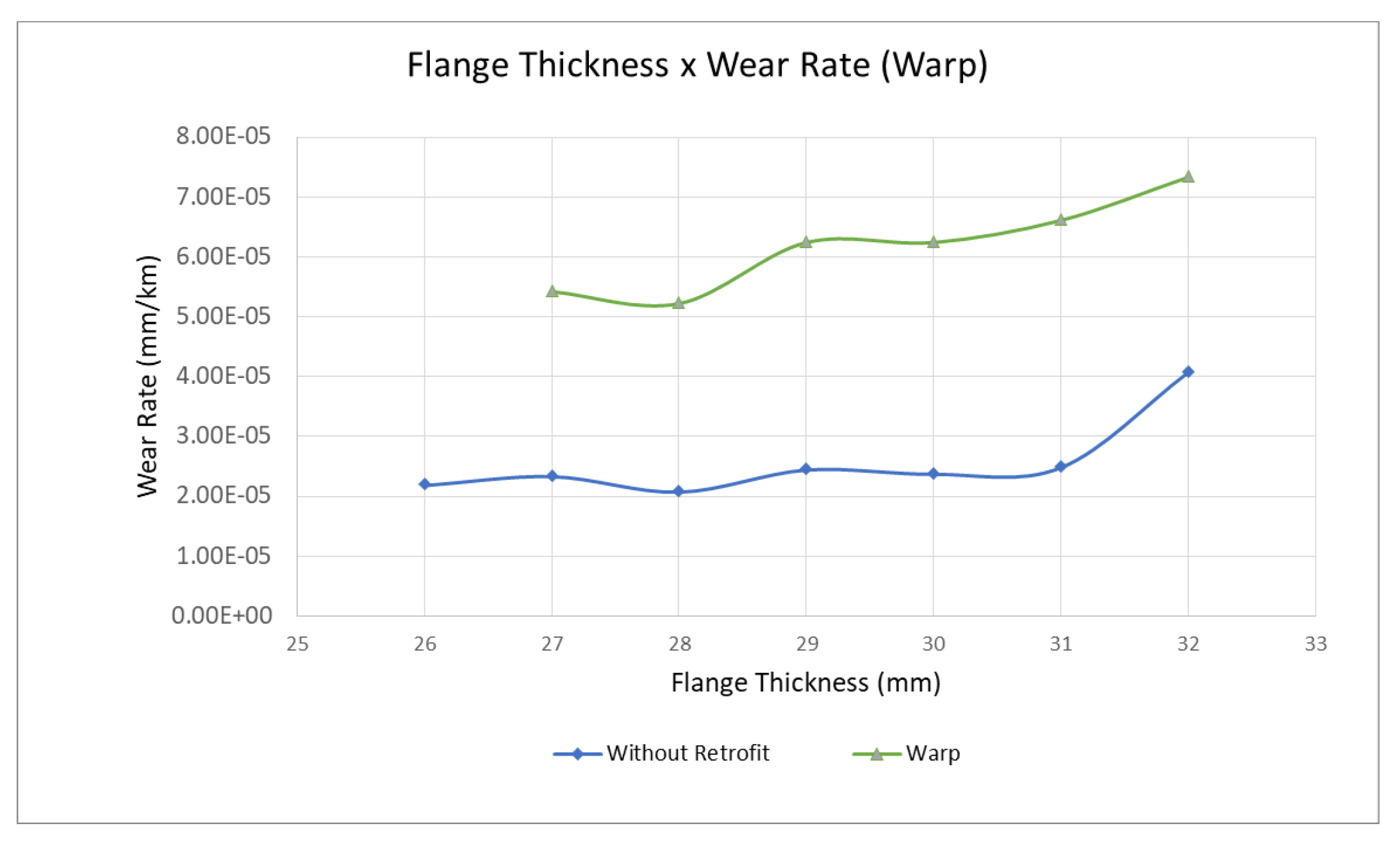
The obtained wear function is the variation in the rate as a function of the flange thickness, with higher values for the new flange (32 mm). This effect can be explained by the smaller difference in the rolling radius of the new wheels in curves, as wheels with thicker flanges reduce the lateral displacement. This condition reduces the steering moment, an important force couple that promotes the curve inscription. It is noteworthy that this behavior justifies the use of wheels with a 32 mm flange instead of a 36 mm initial flange, which would make the wear rate even higher. The obtained wear function is not defined for flanges smaller than 26 mm due to the sampling that was used.
The operation strategy removes wheels from circulation with a 24 mm flange thickness in the off-season. Thus, although the function is not linear, the average wear rate of the sample for all flange thicknesses was 2.5 × 10 mm/km. Considering this rate, it is possible to carry out the maintenance plan by contemplating the need to replace the wheels. Therefore, considering the three useful lives of the wheels, the expected lifespan of the wheel is approximately 9 years. Although there are differences in the hardness of each wheel’s lifespan due to the heat treatment in the manufacturing process, which influences the wear behavior, this projection considers them to have the same performance.
To identify bogies with a poor performance and wheel wear rate that is higher than average, the uneven wedge criterion was used. This provides the warp conditions of the bogie and the angle of attack, even on tangents, and consequently increases the wear rate. This criterion was chosen due to the analysis of the wedge conditions that presented this characteristic. In general, high wedges were not found above 39.7 mm. Among the sample of measured vehicles, a high wear rate was observed in bogies with an unevenness wedge greater than 16 mm on the same side of the bogie. One of these wedges was under the initial height of 17.5 mm. These wagons represented 4.6% of the measured sample, and the worst wheel wear rate was 6.42 × 10
mm/km. The wagons, on average, circulated close to 100,000 km per year, with the bogies with uneven wedges. These spent approximately 4 mm more flange thickness wear per year on wheels with the highest wear rate, representing a useful life expectancy of 4 years.
Figure 9 illustrates the wear rate for the average bogie without retrofitting and for warp bogies with an unevenness greater than 16 mm.
The wear rate values obtained for different bogie maintenance conditions were applied in the modeling developed in Item 3.1 of the methodology. Thus, considering the average costs of bogie correction, wheel replacement, and turning, it is possible to define the best maintenance strategy for minimal costs. The results of the integer linear programming indicated that if the initial wheel wear rate of a vehicle is 6.42 × 10
mm/km, the best strategy is to consider the bogie fixing in the first year, as the maintained bogie can consider two turning costs over a nine-year projection. Therefore, after adding the bogie maintenance cost and two turnings, the total cost will be BRL 3783.00. The costs of the modeling are the current values used in the VLI maintenance budget and are related to the Brazilian market. This result represents a gain in relation to what is currently practiced for this bogie condition, in which the total cost would be BRL 7898.00. This high value is due to the need to replace the wheel, which has a high maintenance cost.
Table 3 presents the integer variable results that were obtained. These values indicate the need to carry out bogie maintenance in year 1. Considering the lower wear rate that occurs after the wagon leaves the workshop for bogie repairs, use of the wheel is guaranteed over the nine expected years of its useful life. It is noteworthy that, during this period, it is necessary to carry out two wheel turnings to recompose the profile in year 3 and year 8.
3.2. Bogie Retrofit Influence
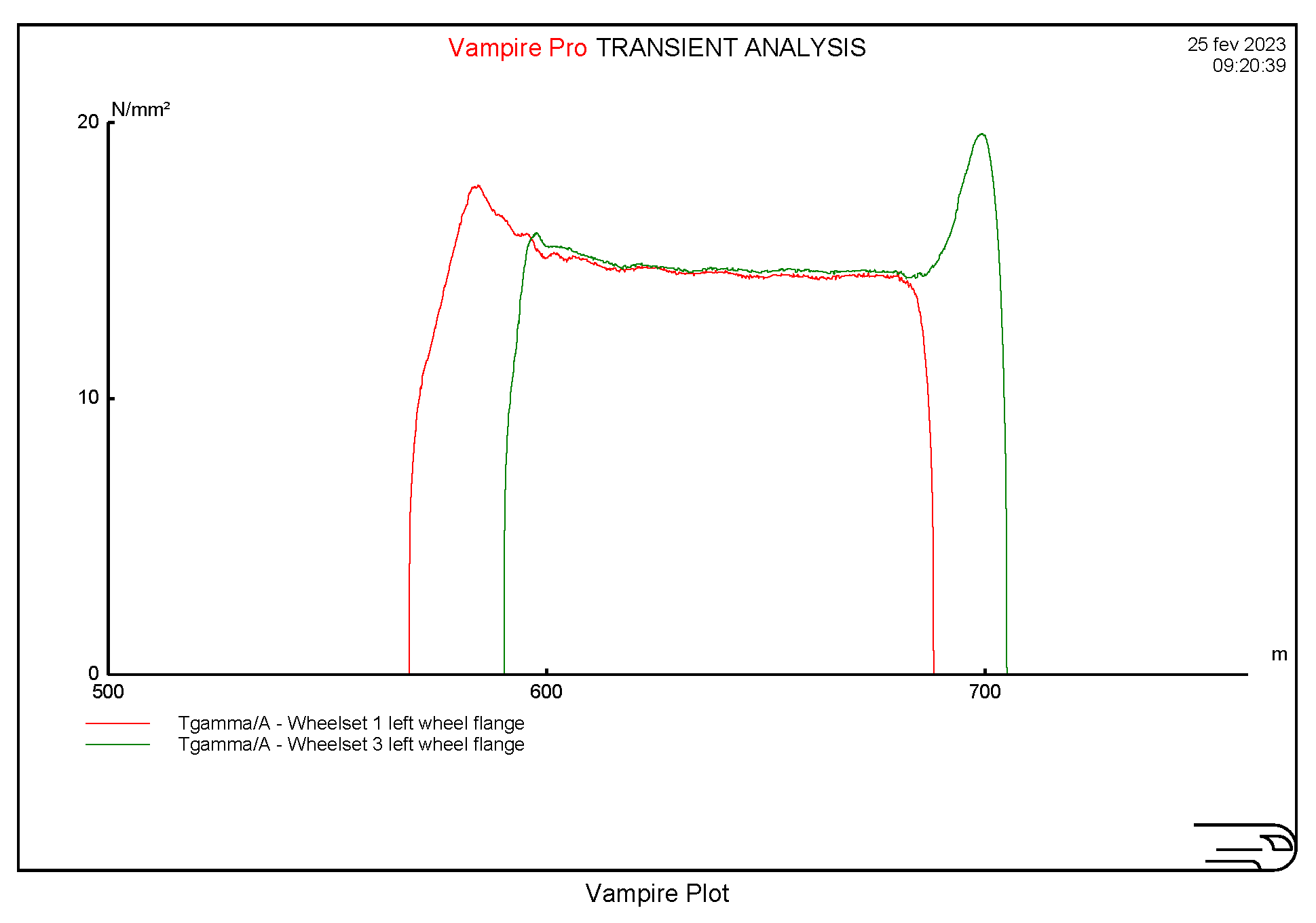
The multibody simulation results using the VAMPIRE software showed a significant decrease in the T
/A indicator when comparing the original ride control bogie design with the proposed retrofit. The graph in
Figure 10 illustrates the retrofitted bogie’s results on the 300 m radius curve for the left-hand wheels. It should be noted that, because the curve considered in the modeling is directed to the right, there will be no flange touch of the inner wheels (right). The used value was the maximum value of all curves.
Table 4 and
Table 5 present the comparative results of T
/A for the current design conditions for empty and loaded HFTs with ride control bogies and the retrofit application according to curve type using different radius values. Examining the table that includes the simulation results and relating it to the Lewis laboratory tests, the wear rate is shown to be constant (55
g/m/mm
2) in the severe wear regime for T
/A values between 10.4 and 77.2 N/mm
2. Thus, in curves with tighter radii that are smaller than 450 m for empty and 400 m for loaded HFT, there is no gain for the retrofitted bogie, even in conditions with lower wear indicator values. However, for curve radii between 450 and 500 m for empty conditions, the wear regime changes and is characterized as medium. In this regime, the wear rate is proportional to T
/A, multiplied by a factor of 5.3. The reduction in the wear indicator is reflected in the wear rate, in which the retrofitted bogie presents a significant percentage gain, reducing the wear rate. For open curve radii greater than 500 m for empty and 400 m for loaded HFT, the retrofitted bogies present an even more favorable behavior to reduce wear. In these curves, which exist in greater quantities, the bogies no longer touch the flange, which directly reduces wear.
It should be noted that the loaded conditions presented lower wheel wear indicator values than empty conditions for the retrofitted bogie. The relationship between the longitudinal force acting on the pad and the pad stiffness can explain this. This force was enough to compress the pad and use the gap between the adapter and the side frame pedestal, resulting in less angle of attack. To extrapolate the results obtained for curves with other radius values, linear regressions were performed, and the functions were found to correlate with the radius with T/A. The regressions showed a high R2 value, indicating a good correlation between the variables; therefore, it is possible to use the linear function. Thus, using the permanent track record for the corridor curves, T/A values were obtained for all curves, considering the circular radius and distance.
(Empty HFT 1L without retrofit ): y = −0.054x + 36.03; R2 = 0.9995;
(Empty HFT 3L without retrofit): y = −0.0406x + 29.01; R2 = 0.9988;
(Empty HFT 1L with retrofit): y = −0.0612x + 35.9; R2 = 0.9976;
(Empty HFT 3L with retrofit): y = −0.0448x + 30.22; R2 = 0.996.
Considering the equations for empty HFT, the retrofit could decrease wheel wear by 33.6%. Considering the regressions for loaded vehicle conditions, the retrofit could reduce wheel wear by 47%. Therefore, as half the time, the HFT cars are running on the empty train, and the other half, they carry soybean to the port, the mean gain in wheel life is 40%. This percentage is in accordance with other, similar studies, which found 43% reductions in wheel wear after applying shear pads. The shear pad has lower stiffness, which can benefit the wheel wear behavior [
20]. However, it was considered inapplicable to the VLI´s side frame, as explained in
Section 2.2.
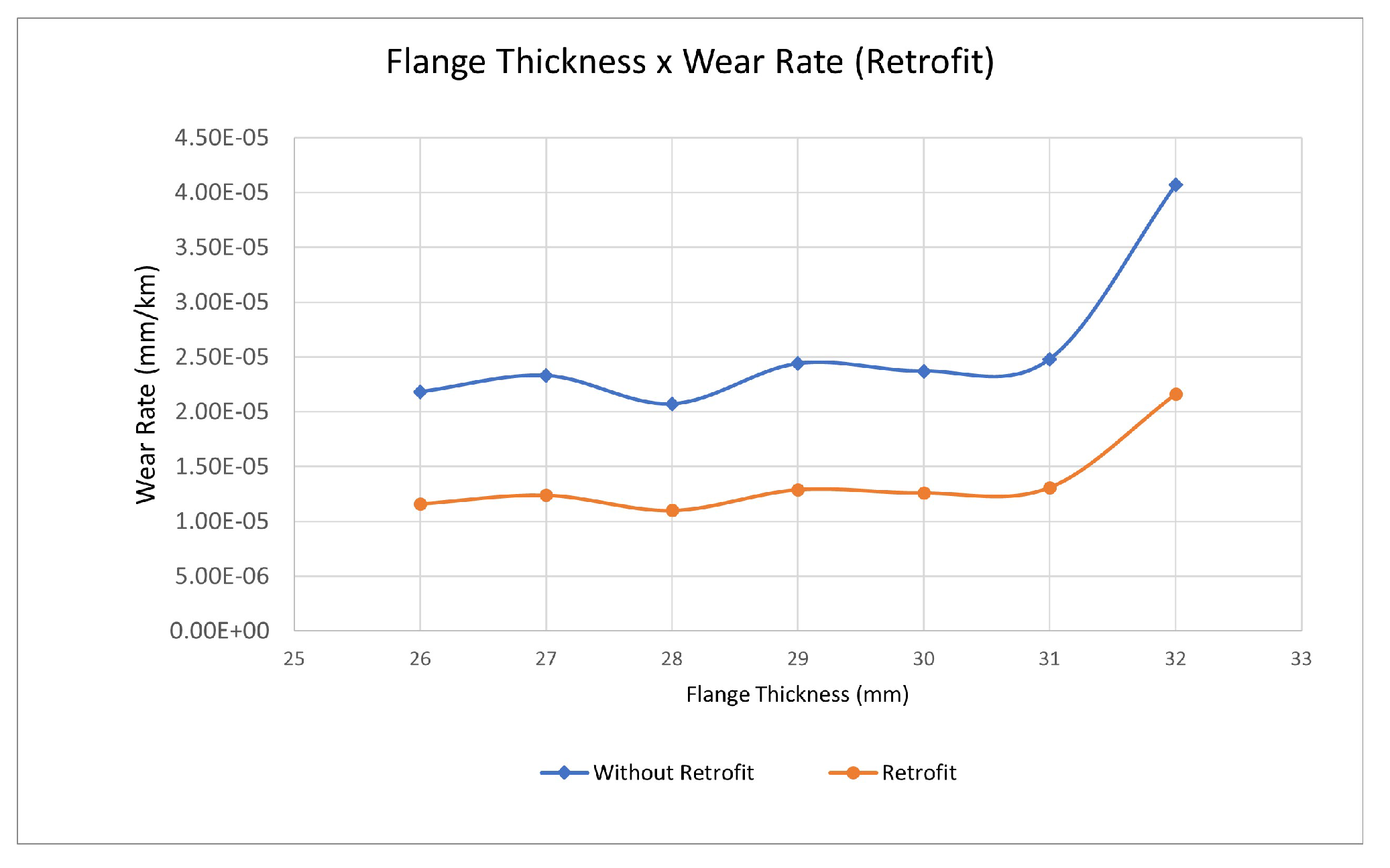
Figure 11 shows the results of the wear rate comparison.
(Loaded HFT 1E without retrofit ): y = −0.091x + 52.91; R2 = 0.9994;
(Loaded HFT 3E without retrofit): y = −0.112x + 55.4; R2 = 1;
(Loaded HFT 1E with retrofit): y = −0.14x + 59.7; R2 = 1;
(Loaded HFT 3E with retrofit): y = −0.112x + 53.2; R2 = 1.
Figure 12 compares the angle of attack in a 300 m radius curve under conditions with the retrofit (red line) and without the retrofit (green line) for a loaded HFT. It is possible to observe that, for this curve, the value of the angle of attack for the bogie with the retrofit is extremely low, culminating in a low lateral slip and, consequently, the wear indicator. The minus sign in the angle value is due to sign convention. This leads to a considerable reduction in the angle of attack for three-piece bogies by 43%. In order to achieve a better behavior, it is necessary to evaluate a different bogie technology, such as the active steering control conception, which could decrease the angle of attack by 92.6%.
It should be noted that this gain was applied to the following boundary conditions: ride control bogie, broad gauge (1600 mm), AAR-1B narrow flange wheel profile, Arema 136RE rail profile, Hopper vehicle, and a track with a mild and sharp curved track.


