1. Introduction
Borehole extraction is the main technical means of gas control at present. Effective extraction radius is an important basis for borehole design, which directly affects the extraction effect. If the hole spacing is too large, it is easy to form a blind area of extraction. If the hole spacing is too small, the effective extraction radius overlaps with each other, which is easy to cause unnecessary waste of manpower and material resources [
1,
2]. For this reason, researchers have carried out shock waves [
3], loose blasting [
4,
5], hydraulic fracturing [
6,
7], CO
2 fracturing [
8,
9] and large borehole [
10,
11] in improving the permeability-increasing of coal seam and increasing the effective extraction radius. It achieved a certain effect of increasing permeability and increasing flow. In addition, many researchers have carried out a lot of fruitful research work on the theoretical solution of gas flow channels and effective radius of extraction, field test technology and other key issues, and achieved a series of results [
12]. Liu et al. [
13] studied the evolution law of mining gas channels and its influence on the law of gas-guided flow. They established the judgment method of the gas channel flow state. Zhang et al. [
14] divided the gas flow channel into mesoscopic channels and macroscopic channels according to the fracture degree of the coal body. They analyzed their formation mechanism and evolution law of them. Xu et al. [
15] studied the unloading damage range of gas channels under different mining heights. Ma et al. [
16,
17] established the model of the plastic zone of a borehole surrounding a rock and gas permeability-increasing circle. He put forward the concept of a high-quality gas channel. Ma et al. [
18] used a similar simulation method to study the formation and evolution mechanism of gas channels in close-distance coal seams.
In summary, the formation of the plastic zone of the surrounding rock of the borehole provides a high-quality channel for gas flow. The distribution pattern of the plastic zone and the characteristics of the connection network are very important for the optimal layout of the gas extraction borehole. However, the current research mainly focuses on the formation and evolution of the plastic zone of the single-hole surrounding rock and the expansion of the plastic zone between the surrounding rock of each borehole. The research on the scientific rationality of the hole spacing is relatively lagging behind, and it also ignores the influence of gas pressure on the plastic zone of the surrounding rock of the borehole. Resulting in a certain blindness and randomness in the actual engineering application, which seriously affects the efficient extraction of gas. Therefore, considering the gas pressure parameter, the implicit equation of the plastic zone boundary of the borehole surrounding rock is derived based on the modified Terzaghi effective stress principle and Mohr-Coulomb strength criterion. The distribution pattern of the plastic zone of the borehole surrounding rock and the variation law of the permeability-increasing circle with the confining pressure ratio, the mechanical parameters of the coal body, the gas pressure and the aperture are analyzed. The distribution pattern of the plastic zone of the borehole surrounding rock is used to establish the honeycomb gas flow network channel structure, which is beneficial to gas extraction. Based on this, the main criterion of the borehole spacing is proposed, and the engineering test is carried out.
2. Mechanical Model of Surrounding Rock for Borehole in Gas Coal Body
The surrounding rock around the gas extraction borehole will form a certain range of plastic zones under the action of in-situ rock stress. A large number of cracks are derived from the plastic zone, and the cracks are the main channels for gas flow. The formation of the plastic zone provides a high-quality channel for gas flow and increases gas permeability. On the basis of predecessors, the mechanical model is established, and the formula is deduced to analyze the influence of various factors on the gas penetrating circle.
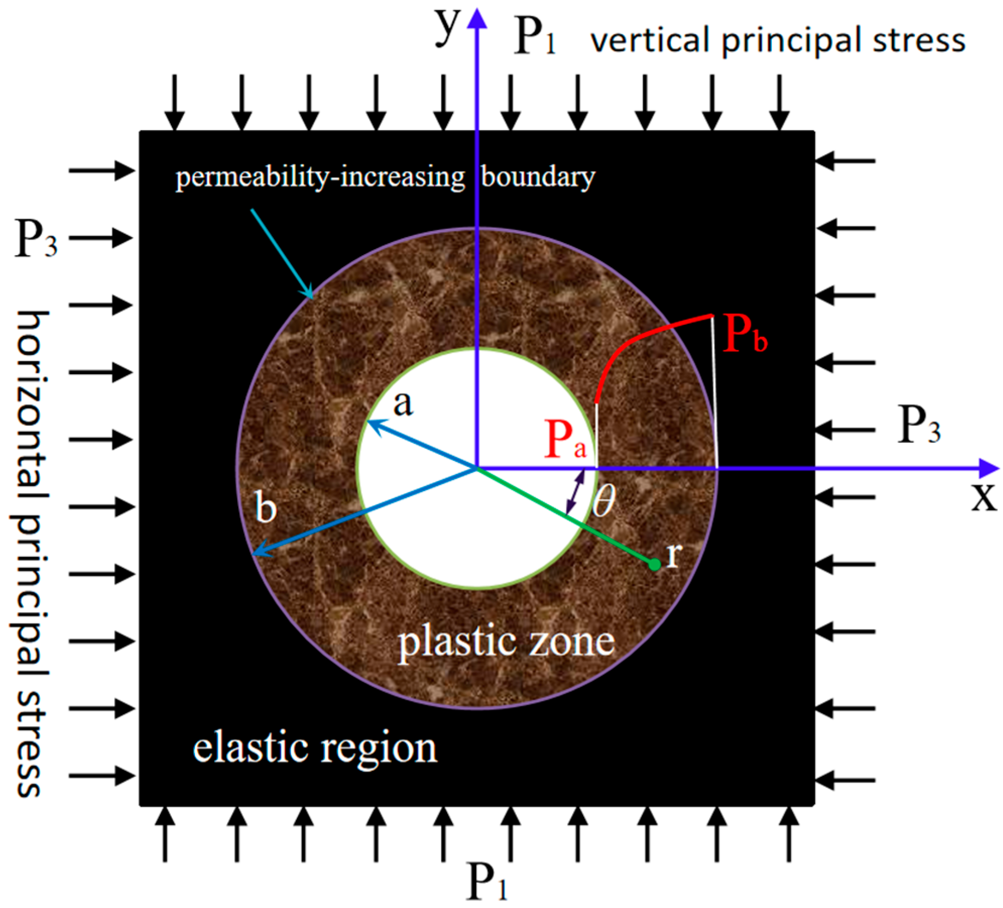
The circular borehole is excavated in the coal seam. The radius of the circular borehole is a. The original gas pressure in the coal seam is Pg. The gas pressure at the free surface of the surrounding rock is Pa. The unit long thole axis is determined along the hole axis, which is an axisymmetric plane strain issue without taking body force into account. To assist the study of the stress state, the mechanical model of the borehole surrounding rock is simplified by assuming that the two-way stress field is a uniformly distributed load. The following fundamental assumptions and the basis of some assumptions are made.
(1) The drilling section is a circular hole with radius a and buried depth H ≥ 20a, which is an infinitely long flat hole; (2) The surrounding rock is an ideal elastic–plastic body, which is an isotropic medium. The coal body with good integrity can be regarded as an isotropic continuous medium; (3) Ignoring the mutual transformation between free gas and adsorbed gas in coal. The adsorption equilibrium of coal is destroyed after pressure relief so that the adsorbed gas becomes free gas. In practice, it must be converted under special circumstances, so it can be ignored; (4) The model’s external boundary conditions are vertical principal stress P1 and horizontal principal stress P3, both of which are parallel to the rectangular coordinate axis.
On this basis, a mechanical model of a circle with increased permeability is developed, as shown in
Figure 1.
3. Gas Pressure Distribution of Surrounding Rock in Boreholes
After excavation, the gas flow in the surrounding rock is axisymmetric radial seepage. The cylindrical gas flow
Q flows across the radius
r per unit length per unit time:
We may obtain from Equation (1):
Using Equation (2) and the boundary conditions of the coal borehole’s surrounding rock,
p(a) =
Pa,
p(b) =
Pg, the following result is obtained:
Substituting Equations (3a) and (3b) into Equation (2) yields the gas pressure distribution law:
4. Theoretical Solutions of the Surround Rock Plastic Zone of the Borehole
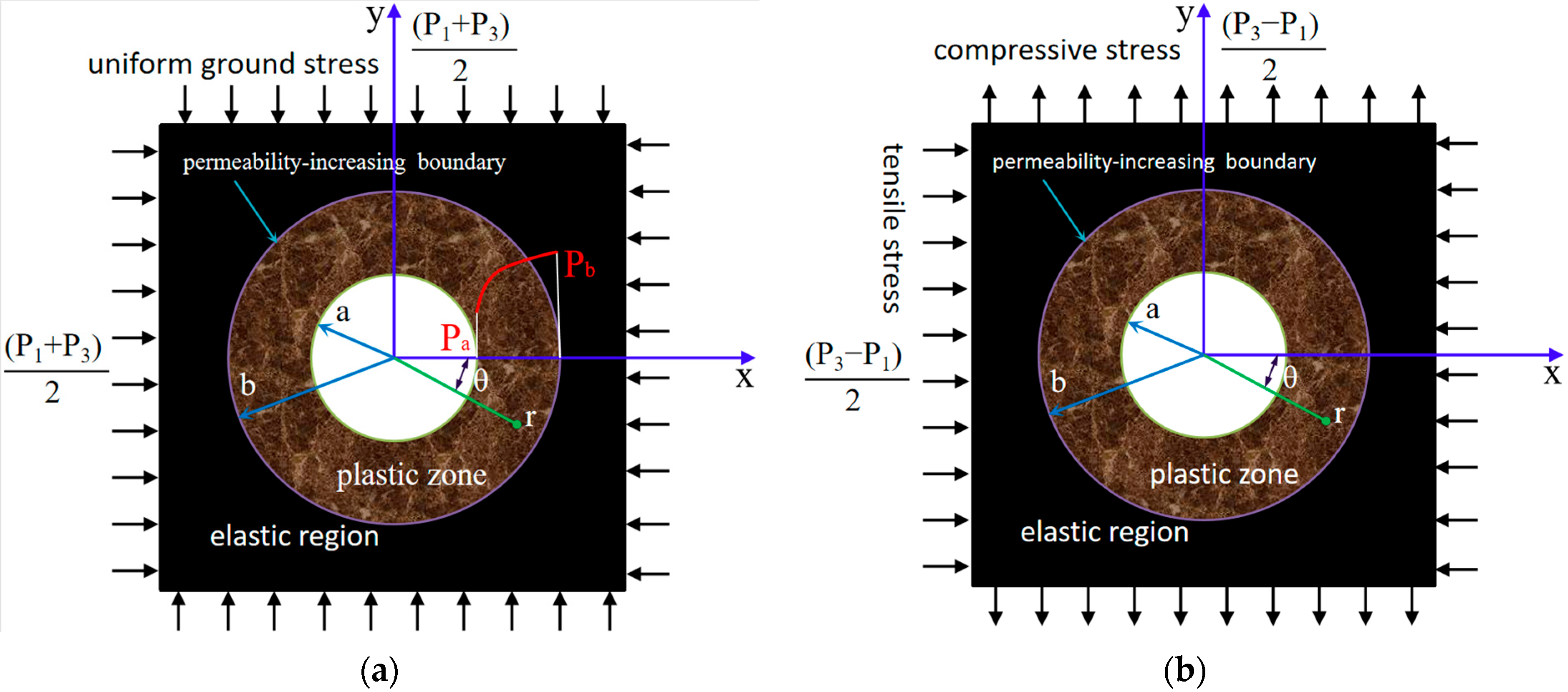
The mechanical model of the borehole surrounding rock in
Figure 1 is decomposed into two parts by the action of two-way ground stress and gas pressure. One part is the uniform ground stress field condition under gas pressure, as shown in
Figure 2a. The other part is to bear the same pressure and tensile stress in the vertical and horizontal directions, respectively, without taking gas pressure into account, as shown in
Figure 2b.
4.1. Theoretical Solution of Stress Field in Borehole Elastic Zone around Rock
4.1.1. Theoretical Solution of Compressive Stress Field of Borehole Surrounding Rock
In the first section,
Figure 2a shows the action of gas pressure. For coal-like materials, according to the modified Terzaghi effective stress principle, the relationship between the effective stress σ′
ij acting on the coal skeleton and the gas pressure
p is it.
The equilibrium equation of axisymmetric plane strain problem ignoring the borehole coal body force is it.
When Equations (4b) and (6) are substituted for Equation (7), the following results are obtained:
Assuming b is large enough, the elastic phase stress expression can be obtained using the calculation model’s geometric equations and boundary conditions as follows:
4.1.2. Theoretical Solution of Borehole Surrounding Rock Pressure and Tensile Stress Field
The second portion is a theoretical solution of the stress field of the borehole’s surrounding rock under pressure and tensile stress, as shown in
Figure 2b.
The stress solution is obviously connected to
r and 2
θ; therefore, let the stress function be it.
The elastic phase stress expression is generated by plugging Equation (11) into the biharmonic sum equation and combining the boundary conditions
r = a,
σr = 0 and
τrθ = 0:
4.1.3. Borehole Surrounding Rock Stress Field Theoretical Solution
The theoretical solution of the elastic stress field of a borehole surrounding rock with gas pressure can be obtained by superimposing the stress components of the first and second parts. That is the addition of Equations (9) and (12). The specific expression is as follows:
4.2. Theoretical Solution of Stress Field in Borehole Plastic Zone around Rock
When the tension in the surrounding rock around the borehole exceeds the strength of the coal body, plastic deformation occurs. A defined range of plastic failure zone extends from the borehole to the depth of the surrounding rock. The surrounding rock stress now fits the Mohr-Coulomb yield requirement, namely:
Let
r be the plastic zone border,
P3 =
λ P1, and plug Equation (14) into Equation (13) to obtain the implicit equation for the plastic zone boundary of the circular drilled hole enclosing rock with regard to
r and
θ, namely:
5. Theoretical Influence of Surrounding Rock Augmented Permeability-Increasing Circle of Coal Borehole
The influencing factors of the permeability-increasing circle of the surrounding rock of the gas drainage borehole mainly include the confining pressure ratio, the strength of the coal body, the gas pressure and the hole diameter, which can be known from Equation (15). Coal strength, gas pressure and hole diameter and other factors, and the influence of each factor on the surrounding rock plastic zone and the permeability-increasing circle of the borehole will be analyzed in detail. With the help of Matlab calculation software and based on Equation (15), the influence of various factors on the plastic zone and permeability-increasing circle of the borehole permeability-increasing circle will be analyzed in detail.
5.1. Effect of Confining Pressure Ratio on Permeability-Increasing Circle of Borehole
Surrounding Rock
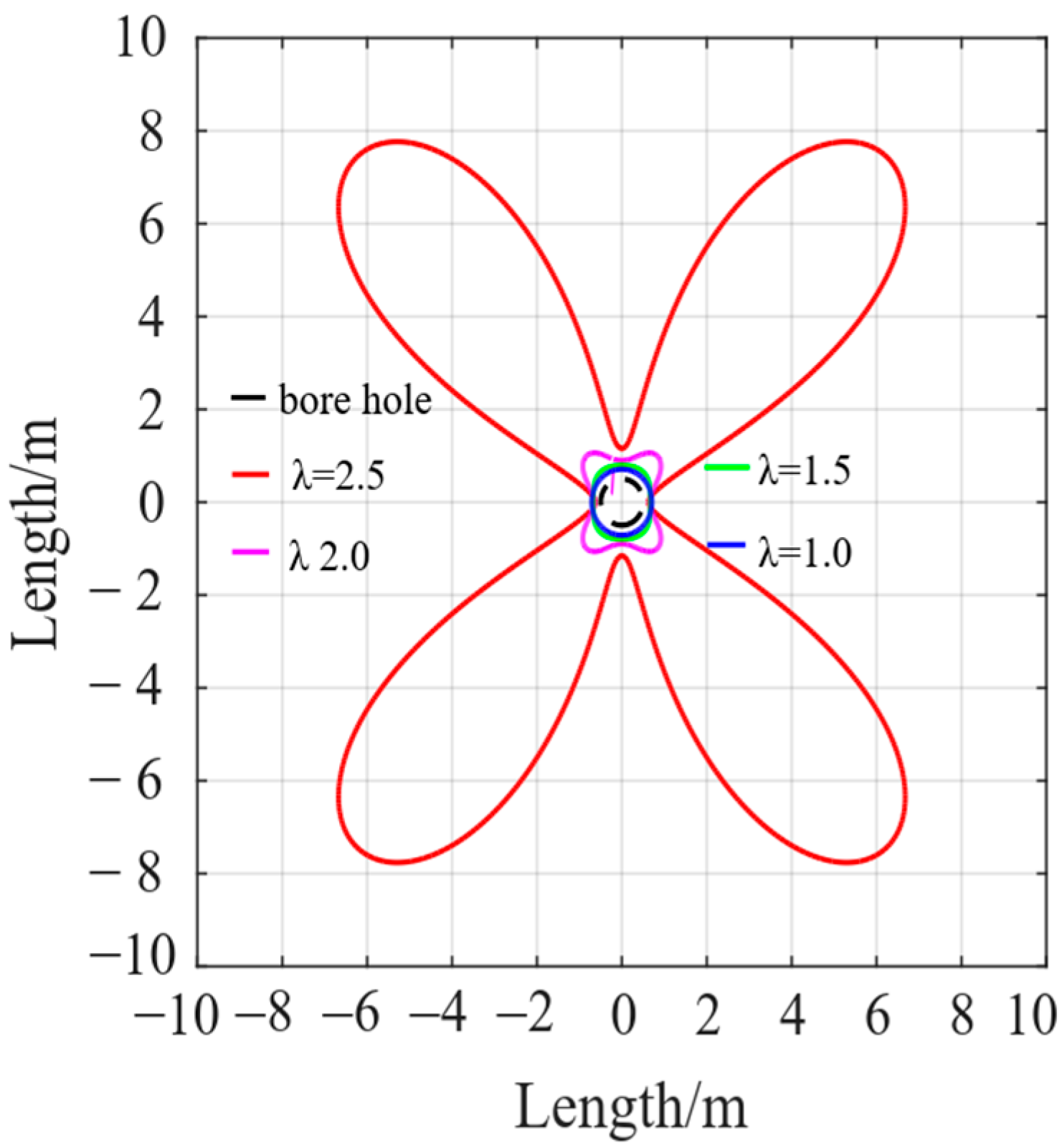
Under the condition of certain mechanical properties of the borehole surrounding rock, gas pressure and hole diameter, the two-way confining pressure ratio determines the shape and range of the plastic zone of the borehole surrounding rock, as shown in
Figure 3. When the confining pressure ratio is equal to 1, the plastic zone of the surrounding rock of the borehole is circular. As the confining pressure ratio gradually increases, the distribution pattern of the plastic zone changes from circular to elliptical and butterfly. After the formation of the butterfly-shaped plastic zone, with the continuous increase of the confining pressure ratio, the four butterfly leaves in the plastic zone expand rapidly at a high rate, and the failure range of the surrounding rock expands rapidly.
In order to obtain the borehole surrounding the rock permeability-increasing circle, the distribution pattern of the plastic zone is drawn, and the permeability-increasing radius R max acquisition method is shown in
Figure 4. When the plastic zone is circular, the plastic zone’s range is the range of increased permeability. The butterfly leaf length of the butterfly plastic zone is the surrounding rock permeability-increasing radius R
max for non-circular plastic areas, such as butterfly plastic areas. The butterfly leaf is longer, and the permeability-increasing range is larger. It is more conducive to efficient gas extraction.
The effective extraction radius of gas is the permeability-increasing radius, and its size directly impacts the gas extraction effect; The permeability-increasing radius bigger, the more favorable to gas extraction. Based on the findings in
Figure 5, When the borehole’s confining pressure is low, the permeability-increasing radius of the surrounding rock is very tiny; when the confining pressure ratio grows, the permeability-increasing radius increases continually. When the confining pressure ratio approaches 2.5, the permeability-increasing radius climbs to 14 m. It is 28 times the borehole radius, demonstrating that a high confining pressure ratio is particularly helpful to gas extraction.
5.2. The Influence of Coal Strength on Borehole Surrounding Rock
Permeability-Increasing Circle
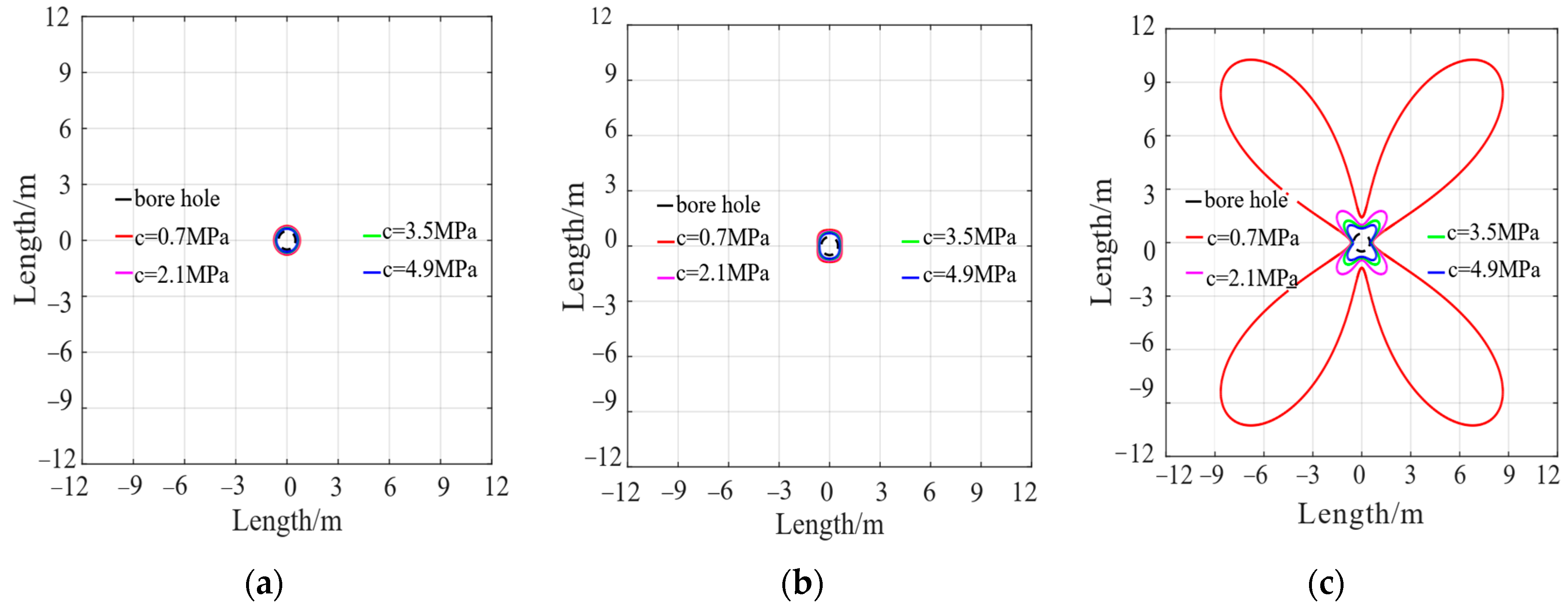
The distribution pattern and range of plastic zone in the borehole surrounding rock are directly related to the strength of the coal body. As the main parameters to characterize its strength, cohesion and internal friction angle of the coal body must become the key factors affecting the permeability radius of surrounding rock. The relationship between the distribution of the plastic zone of the borehole surrounding rock and the cohesion and internal friction angle of the coal body is shown in
Figure 6 and
Figure 7. The relationship between permeability-increasing radius and coal cohesion and internal friction angle is shown in
Figure 8 and
Figure 9.
When the plastic zone is circular or elliptical, the impact of cohesion or internal friction angle on its distribution is generally small. The capacity of the plastic zone to keep its original form rapidly reduces with increasing cohesion or internal friction angle, and it eventually approaches the empty surface of the borehole’s surrounding rock. As illustrated in
Figure 6a,b and
Figure 7a,b. The four butterfly leaves deteriorate fast when the plastic zone is butterfly-shaped. The smaller the cohesiveness or internal friction angle, the more sensitive to the degradation rate of the four butterfly leaves in the plastic zone. As illustrated in
Figure 6c and
Figure 7c.
From the analysis of
Figure 8 and
Figure 9, it is found that when the plastic zone is circular or elliptical, the sensitivity of the permeability-increasing radius to the cohesion or internal friction angle is relatively weak. Additionally, it decreases approximately linearly with the increase of the two. When the cohesion and internal friction angle increase to a certain value, the permeability-increasing effect of the plastic zone is almost zero. For the butterfly plastic zone, when the cohesion and internal friction angle is small, the permeability-increasing radius is very sensitive to the two and increases nonlinearly with the decrease of the two. It’s very beneficial to gas drainage. As the cohesion and internal friction angle continue to increase, the sensitivity of the permeability-increasing radius to the two is gradually weakened. The permeability-increasing radius is continuously reduced. The range of gas flow channels is gradually reduced. The surrounding rock gradually loses the permeability-increasing effect.
Therefore, the increase in coal strength has a certain inhibitory effect on the formation of gas flow channels. Theoretically proves the fact that a hard coal body is extremely unfavorable to efficient gas extraction.
5.3. Effect of Gas Pressure on the Permeability-Increasing Circle of the Borehole
Surrounding Rock
Gas pressure is an important parameter for determining the flow and occurrence state of a coal seam, and it is a key factor in the study of coal and gas outbursts and gas extraction. As it affects the strength and solidity of coal to varying degrees, and the surrounding rock plastic zone exhibits an obvious gas pressure effect [
19].
Figure 10 depicts the relationship between the distribution pattern of the plastic zone of the borehole’s surrounding rock and the gas pressure when all other influencing factors are held constant.
Figure 11 depicts the relationship between the perimeter rock permeability-increasing radius and the gas pressure. When the plastic zone is circular or oval, the gas pressure has minimal influence on how the plastic zone is distributed. As seen in
Figure 10a,b, the plastic zone retains its initial form and gradually expands with increasing gas pressure. When the plastic zone is butterfly-shaped, the impact of gas pressure on it is likewise expressed as the growth of four butterfly leaves. As illustrated in
Figure 10c.
The higher the gas pressure, the faster the butterfly leaf grows. The sensitivity of the surrounding rock’s plastic zone permeability-increasing growing radius to gas pressure is rather weak when it is circular or elliptical. It grows approximately linearly and slowly with rising gas pressure. For the butterfly plastic zone, when the gas pressure is small, the sensitivity of the permeability-increasing radius to the gas pressure is weak. As the gas pressure continues to increase, this sensitivity increases rapidly. The increase mode changes from approximately linear to nonlinear, as shown in
Figure 11.
5.4. Effect of Hole Diameter on the Permeability-Increasing Circle of the Borehole
Surrounding Rock
The hole diameter of gas extraction has a significant impact on the permeability-increasing radius of the surrounding rock. Increasing the hole diameter is a crucial step toward increasing the rate of gas extraction.
Figure 12 depicts the distribution pattern of plastic zones with borehole radii of 0.1 m, 0.3 m, 0.5 m, and 0.7 m.
Figure 13 depicts the link between the surrounding rock permeability-increasing radius and the borehole radius.
If the confining pressure ratio, coal strength, and gas pressure remain constant, changing the hole diameter will not change the distribution pattern of the plastic zone. However, it will affect its size, and the original distribution pattern of the plastic zone will increase with increasing hole diameter. As shown in
Figure 12. According to the study of
Figure 13, there is a linear positive association between the surrounding rock’s permeability-increasing radius and the hole diameter, which means that the permeability-increasing radius grows linearly as the hole diameter increases. When the mechanical qualities of coal are constant, and the gas pressure is constant, the confining pressure ratio dictates the rate of expansion of the surrounding rock’s permeability-increasing radius with hole diameter. The permeability-increasing radius of the high surrounding rock ratio (such as the butterfly plastic zone) grows at a faster pace than the tiny confining pressure ratio (such as the circular plastic zone). When conditions allow, the hole diameter should be expanded as much as feasible to widen the permeability-increasing radius and generate a larger range of gas flow channels.
6. Construction Method and Engineering Implementation Significance
6.1. Channel Structure Construction Method of Honeycomb Gas Flow Network
The major technological means of gas control are boreholes and extraction. The effective extraction radius is a significant basis for the design of the extraction borehole, which directly influences the extraction effect. According to the theoretical analysis shown above, the permeability-increasing radius of the borehole’s surrounding rock is directly connected to the confining pressure ratio, coal strength, and other parameters. When the plastic zone of the borehole’s surrounding rock is round or oval, the impact of coal strength, gas pressure, and hole diameter on the perimeter is small. When the plastic zone of the borehole’s surrounding rock is butterfly-shaped, the permeability-increasing circle is more sensitive to changes in coal strength, gas pressure, and hole diameter. The lower the coal strength or, the higher the gas pressure, the greater the sensitivity. Under the actual engineering geological conditions, the stress environment of coal seam surrounding rock, coal strength and gas pressure has existed objectively, which are not controllable human factors. As controllable factors, hole diameter and hole spacing usually expand the permeability-increasing range by increasing hole diameter and reducing hole spacing so as to realize gas flow and efficient extraction.
Although increasing the hole diameter can raise the permeability-increasing radius of the surrounding rock and enhance the gas extraction rate to some extent, it also increases the building complexity, expense, and hazard. As a result, scientific and acceptable hole spacing has become the primary technical solution to increase the gas extraction rate. However, its layout is blind and lacks scientific theoretical direction. If the hole spacing is too big, it is simple to produce a blind extraction region. If the hole spacing is too narrow, the permeability-increasing range overlaps, resulting in excessive waste of human and material resources. Based on the foregoing considerations, a honeycomb gas flow network channel structure was established based on the distribution pattern of the borehole’s surrounding rock. Additionally, the scientific and reasonable gas extraction hole spacing was determined by combining the coal seam stress environment and the mechanical properties of the coal body. The gas flow network channel structure conducive to gas extraction is created through the expansion and connection of the borehole’s surrounding plastic rock zone. The connection of gas enrichment areas is realized. The flow of coal seam gas is promoted. The best gas extraction effect is achieved.
The general idea of the Structure of a Honeycomb Gas Flow Network Channel (SHGFNC) is based on the distribution of plastic zone in the borehole surrounding rock, and the key to forming this structure is to determine the scientific and reasonable hole spacing. If the hole spacing is too small, the plastic zones of the surrounding rock of each borehole overlap with each other, which increases the cost of gas extraction. When the hole spacing is too large, the plastic zones of the surrounding rock of each borehole are independent of each other. It will form an independent channel structure of gas flow with a limited permeability-increasing range (as shown in
Figure 14), which is obviously not conducive to the flow of gas between the surrounding rocks of the borehole.
Scientific and reasonable gas drainage hole spacing should enable the plastic zone of each borehole surrounding rock to expand and form a honeycomb gas flow network channel structure, which promotes the flow of gas in the structure. It realizes the interoperability of gas flow in each borehole surrounding rock during gas drainage. Additionally, reduce the overlap of plastic zone expansion and reduce the cost of gas drainage. For example, for the extraction of coal seam gas in a uniform or approximately uniform stress environment, at the initial stage of borehole unloading. A large amount of elastic energy stored in the surrounding rock mass is released. The plastic zone of the surrounding rock of each hole expands independently. After that, due to the strong coupling and pressure relief between the surrounding rocks of adjacent boreholes [
20], the plastic zone of each hole expands to the adjacent plastic zone in a convex shape in the horizontal and vertical directions, forming an approximate honeycomb gas flow network channel structure, as shown in
Figure 15a,b. For the borehole extraction of coal seam gas in a high deviatoric stress environment, the plastic zone expansion of borehole surrounding rock is mainly subjected to high deviatoric stress. The formation of the honeycomb gas flow network channel structure is through the expansion of butterfly leaves in the plastic zone of the surrounding rock of each borehole, as shown in
Figure 15c. In the test of Puxi Mine, the expansion and permeability-increasing of the plastic zone of the surrounding rock can be effectively realized when the borehole spacing is 5 m. Too small or too large hole spacing will produce unsatisfactory results, increase costs or affect the gas circulation effect.
6.2. SHGFNC Project Realization Significance
In summary, the existence of butterfly plastic zone in high deviatoric stress environments can effectively expand the permeability-increasing radius of borehole surrounding rock. Under the condition of constant coal strength, gas pressure and borehole diameter, the stress environment can produce butterfly plastic damage. It can be created by coordinating mining engineering activities. A honeycomb network channel structure conducive to gas flow can be formed to promote the directional flow of gas. For example, the protective layer mining combined with the gas borehole extraction of the protected layer is recognized as the most effective outburst coal seam gas prevention and control technology. The pressure relief of the protective layer mining causes the vertical stress to decrease and the horizontal stress to increase in the adjacent protected coal seam. The stress field is transformed from uniform to non-uniform [
21,
22]. By laying scientific and reasonable gas extraction boreholes in the protected layer, a honeycomb gas flow network channel structure is established to achieve efficient extraction of coal seam gas.
7. Engineering Test
Jia He Mining Co, Ltd.’s (Hong Kong, China) Pu Xi Jing mine is located in Jia He County, Chen Zhou City, Hunan Province, with an annual production capacity of 150,000 tons. The main mining V coal. Coal seam has a thickness of 0–13 m; the average is 2.1 m. Its strength is low. The gas permeability-increasing is poor. The gas pressure is high. The extraction rate is low. Since the mine was put into operation, there have been 106 outstanding accidents. Additionally, the gas disaster has been serious. The geological structure of Pu Xi Jing is complex: folds are well-developed, and the structural stress is strong. Vertical principal stress is 5.4 Mpa; Horizontal maximum principal stress is 15.4 Mpa.
In order to quickly eliminate the outstanding danger and improve the gas extraction rate, based on the channel structure theory of cellular airflow networks and the actual situation at Jia He Mine Pu Xi Well, 2454 floor lanes were selected as the gas extraction borehole layout. The hole spacing is 5 m, and the borehole diameter is 87 mm. Additionally, the boreholes are connected to the pipe network for extraction. After 50 days of extraction, the effect test of the gas content of the coal seam on the 2454 working face was carried out, and the results are shown in
Table 1 and
Figure 16. The steps of the test are as follows.
- (1)
Construction extraction drilling. Drilling extraction is carried out at the selected location, and different apertures and spacings are selected for construction.
- (2)
Sealing and connecting pipe. The hole is sealed with a pre-prepared stopper or polyurethane, and the mixed liquid of cement mortar, expansion agent and accelerator is slowly injected into the hole with a grouting pump for sealing. After the construction of the extraction borehole is completed, the borehole is sealed in time, and the connecting pipe is connected in time.
- (3)
Observation data. The data of extraction parameters (negative extraction pressure, extraction concentration, mixed flow, etc.) were observed and recorded every day.
From the analysis of
Table 1, the expansion and connection of the plastic zone of the surrounding rock of the borehole can be effectively realized when the borehole spacing is 5 m. This can create a gas flow network and channel structure conducive to gas extraction when the residual gas content and gas pressure are all within the standard range, the gas extraction rate is as high as 72.4%, and the gas concentration on the working face does not exceed the limit. It achieves the purpose of de-prominence. The field extraction effect shows that the gas elimination result is good.
8. Conclusions
- (1)
The implicit boundary equation of the borehole’s surrounding rock is obtained. The two-way confining pressure ratio determines the distribution pattern and range of the plastic zone of the borehole surrounding rock. The distribution range of the plastic zone is affected by coal strength, gas pressure, and hole diameter. The distribution patterns of the plastic zone are mostly circular, elliptical, and butterfly.
- (2)
As coal strength decreases and gas pressure and hole diameter grow, the permeability-increasing circle of borehole surrounding rock widens. The extension of the permeability-increasing ring promotes gas flow.
- (3)
A honeycomb gas flow network channel structure based on the distribution morphology of the borehole’s surrounding rock is presented. Realize the linkage of the coal seam gas flow enrichment region and promote gas flow communication in the surrounding rock of each borehole.
- (4)
A honeycomb gas flow network channel structure may be formed by the borehole’s surrounding rock with butterfly, oval, and round plastic zones. The butterfly form is linked by the extension of the butterfly leaf in the plastic zone of the surrounding rock of the neighboring borehole, while the circular and oval plastic zones are stretched horizontally and vertically in a convex shape.
- (5)
The engineering test results demonstrate that the honeycomb gas flow network channel construction based on the plastic zone distribution pattern can effectively increase the gas extraction rate. It can help with borehole spacing design, position selection, and determining the direction for optimal gas extraction.
Author Contributions
Conceptualization, C.Y.; methodology, C.Y.; text editing, correction, L.-X.L.; numerical simulation, J.-J.W. and L.F.; engineering experiments, Y.-Y.X.; normal analysis, C.Y.; writing—preparation of the original, C.Y.; writing-review and editing, C.Y. All authors have read and agreed to the published version of the manuscript.
Funding
National Natural Science Foundation of China (52274080), Natural Science Foundation of Hunan Province (2021JJ40211), Hunan Provincial Department of Education Outstanding Youth Fund Project (21B0486), The Open Foundation of Work Safety Key Lab on Prevention and Control of Gas and Roof Disasters for Southern Coal Mines (E22319).
Institutional Review Board Statement
Not applicable.
Informed Consent Statement
Not applicable.
Data Availability Statement
Not applicable.
Conflicts of Interest
The authors declare no conflict of interest.
Abbreviations
| P | pore gas pressure at r |
| K | permeability coefficient |
| σ′ij | the effective stress tensor |
| σij | the stress tensor generated by external load |
| a | the effective stress coefficient |
| δij | the Kronecker symbol |
| τrθ | the shear stress of a point in the borehole’s surrounding rock in polar coordinates |
| θ | the point’s polar angle coordinate |
| c | ohesion(MPa) |
| φ | the angle of internal friction (°) |
References
- Liu, S.; Ma, G.; Lu, J.; Lin, B. Relative pressure determination technology for effective radius found on gas content. J. China Coal Soc. 2011, 36, 1715–1719. [Google Scholar]
- Chen, J.; Tao, K.; Zeng, B.; Liu, L.; Zhao, H.; Zhang, J.; Li, D. Experimental and numerical investigation of the tensile performance and failure process of a modified Portland cement. Int. J. Concr. Struct. Mater. 2022, 16, 61. [Google Scholar] [CrossRef]
- Yuan, C.; Cao, L.; Wang, W.; Fan, L.; Huang, C. Case Study on Rock Support Technology for Roadways Based on Characteristics of Plastic Area. KSCE J. Civ. Eng. 2021, 25, 705–723. [Google Scholar] [CrossRef]
- Lou, J.; Gao, F.; Li, J.; Yuan, G.; Sharifzadeh, M. Effect of dynamic loading conditions on the dynamic performance of MP1 energy-absorbing rockbolts: Insight from laboratory drop test. Int. J. Min. Sci. Technol. 2023, 33, 215–231. [Google Scholar] [CrossRef]
- Guo, D.; Zhao, J.; Lu, P.; Zhu, T. Effective fracture zone under deep-hole cumulative blasting in coal seam. Chin. J. Eng. 2019, 41, 582–590. [Google Scholar]
- Huang, B.; Cheng, Q.; Chen, S.; Zhang, T. Study of coal seam outburst mitigation by deep hole hydro-fracturing and shallow hole methane drainage. J. China Univ. Min. Technol. 2013, 42, 701–711. [Google Scholar]
- Chen, J.; Liu, L.; Zeng, B.; Tao, K.; Zhang, C.; Zhao, H.; Li, D.; Zhang, J. A constitutive model to reveal the anchorage mechanism of fully bonded bolts. Rock Mech. Rock Eng. 2023, 56, 1739–1757. [Google Scholar] [CrossRef]
- Zhang, D.; Bai, X.; Yin, G.; Rao, Z.; He, Q. Research and application on technology of increased permeability by liquid CO2 phase change directional jet fracturing in low-permeability coal seam. J. China Coal Soc. 2018, 43, 1938–1950. [Google Scholar]
- Zhao, L.; Wang, Z.; Sun, J.; Tu, D. Application of permecbility improvment technology with liquid CO2 phase transition fracturing to high gassy and low permeability seam. Coal Sci. Technol. 2016, 44, 75–79. [Google Scholar]
- Chen, J.; Wei, J.; Zhang, G.; Wang, L. Study on permeability improvement technology of the large-diameterdrilling combined with hole protection. Coal Sci. Technol. 2018, 46, 73–77. [Google Scholar]
- Xie, S.; Yang, B.; Zhang, Q.; Song, H.; Suo, H.; Zhang, T. Research on lift pressure system with combined pipeline and intensive drill-hole gas drainage along the layer in low permeability coal seam. J. Min. Sci. Technol. 2019, 4, 34–40. [Google Scholar]
- Zou, S.; Xin, S. Effective extraction radius of gas drilling in coal seam. China Saf. Sci. J. 2020, 30, 53–59. [Google Scholar]
- Liu, H.; Cheng, Y.; Chen, H.; Kong, S.; Xu, C. Characteristics of mining gas channel and gas flow properties of overlying stratum in high intensity mining. J. China Coal Soc. 2012, 37, 1437–1443. [Google Scholar]
- Zhang, Y.; Xu, L.; Liu, K.; Li, Y.; Zhang, B.; Li, W. Formation mechanism and evolution laws of gas flow channel in mining coal and rock. J. China Coal Soc. 2012, 37, 1444–1450. [Google Scholar]
- Xu, Y.; Li, C.; Zhang, Y.; Wang, H.; Wei, W. Unloading damage evolution and drainage verification of gas flow channel in different mining heights. J. China Coal Soc. 2018, 43, 2501–2509. [Google Scholar]
- Ma, N.; Li, J.; Zhao, X.; Zhao, Z.; Liu, H.; Jia, H. High quality gas channel and its construction method applied to coal and gas in deep mining. J. China Coal Soc. 2015, 40, 742–748. [Google Scholar]
- Ma, N.; Guo, X.; Zhao, X.; Li, J.; Yan, Z. Theoretical analysis and application about permeability-increasing radius of drilling for simultaneous exploitation of coal and gas. J. China Coal Soc. 2016, 41, 120–127. [Google Scholar]
- Ma, H.; Wang, W.; Li, C.; Shi, W.; Yuan, A.; Liu, W. Evolution of crack field and formation mechanism of advantage gas channels in superposition mining. China Saf. Sci. J. 2017, 27, 133–138. [Google Scholar]
- Zhang, J. Experimental study on influence of gas pressure on strength of coal body under adsorption condition. Saf. Coal Mines 2020, 50, 26–29. [Google Scholar]
- Ge, D.; Li, D.; Jiang, F.; Wang, C.; Chen, Y.; Dong, C.; Sun, S.; Yang, G. Reasonable pressure-relief borehole spacing in coal of different strength. J. Min. Saf. Eng. 2020, 37, 578–593. [Google Scholar]
- Guo, H. Analysis on spatial and temporal characteristics of outburst prevention effect in protective seam mining. China Saf. Sci. J. 2019, 29, 108–113. [Google Scholar]
- Chen, Y.; Wu, H.; Zhang, M.; Wu, Y.; Zhang, H.; Zhang, G. Research on the upper protective coal seam mining effect induced by coal thickness and interburden rock properties. J. Min. Saf. Eng. 2016, 33, 578–584. [Google Scholar]
Figure 1.
Force model of surrounding rock of borehole.
Figure 1.
Force model of surrounding rock of borehole.
Figure 2.
Force decomposition of surrounding rock of borehole. The (a) is the radius of borehole, (b) is the radius of plastic zone.
Figure 2.
Force decomposition of surrounding rock of borehole. The (a) is the radius of borehole, (b) is the radius of plastic zone.
Figure 3.
Plastic zone distribution patterns in borehole surrounding rock with varying confining pressure ratios.
Figure 3.
Plastic zone distribution patterns in borehole surrounding rock with varying confining pressure ratios.
Figure 4.
Plastic zone shape and gas permeability-increasing circle of surrounding rock of boreholes under different confining pressure ratios. (a) Round (b) Oval (c) Butterfly.
Figure 4.
Plastic zone shape and gas permeability-increasing circle of surrounding rock of boreholes under different confining pressure ratios. (a) Round (b) Oval (c) Butterfly.
Figure 5.
Confining pressure ratio and permeability-increasing radius of borehole surrounding Rock.
Figure 5.
Confining pressure ratio and permeability-increasing radius of borehole surrounding Rock.
Figure 6.
Distribution patterns of plastic zones in surrounding rock of boreholes under different cohesion. (a) Round (b) Oval (c) Butterfly.
Figure 6.
Distribution patterns of plastic zones in surrounding rock of boreholes under different cohesion. (a) Round (b) Oval (c) Butterfly.
Figure 7.
Distribution patterns of plastic zones in surrounding rock of boreholes under different internal friction angles. (a) Round (b) Oval (c) Butterfly.
Figure 7.
Distribution patterns of plastic zones in surrounding rock of boreholes under different internal friction angles. (a) Round (b) Oval (c) Butterfly.
Figure 8.
Permeability-increasing radius and cohesive force of borehole surrounding rock.
Figure 8.
Permeability-increasing radius and cohesive force of borehole surrounding rock.
Figure 9.
Permeability-increasing radius and internal friction angle of borehole surrounding rock.
Figure 9.
Permeability-increasing radius and internal friction angle of borehole surrounding rock.
Figure 10.
Distribution patterns of plastic zones in surrounding rocks of borehole holes under different gas pressures. (a) Round (b) Oval (c) Butterfly.
Figure 10.
Distribution patterns of plastic zones in surrounding rocks of borehole holes under different gas pressures. (a) Round (b) Oval (c) Butterfly.
Figure 11.
The permeability-increasing radius of the borehole surrounding rock and gas pressure.
Figure 11.
The permeability-increasing radius of the borehole surrounding rock and gas pressure.
Figure 12.
Distribution of plastic zones in surrounding rocks of boreholes with different diameters. (a) Round (b) Oval (c) Butterfly.
Figure 12.
Distribution of plastic zones in surrounding rocks of boreholes with different diameters. (a) Round (b) Oval (c) Butterfly.
Figure 13.
The permeability-increasing radius of borehole surrounding rock and borehole radius.
Figure 13.
The permeability-increasing radius of borehole surrounding rock and borehole radius.
Figure 14.
Independent structure for gas flow channel. (a) Circular plastic zone (b) Oval plastic zone (c) Butterfly plastic zone.
Figure 14.
Independent structure for gas flow channel. (a) Circular plastic zone (b) Oval plastic zone (c) Butterfly plastic zone.
Figure 15.
Structure of honeycomb gas flow network channel. (a) Circular plastic zone (b) Oval plastic zone (c) Butterfly plastic zone.
Figure 15.
Structure of honeycomb gas flow network channel. (a) Circular plastic zone (b) Oval plastic zone (c) Butterfly plastic zone.
Figure 16.
Gas concentration change curve.
Figure 16.
Gas concentration change curve.
Table 1.
Evaluation of extraction effect.
Table 1.
Evaluation of extraction effect.
| Evaluating Indicator | Critical
Exponent | Targeted Value | Outburst Elimination
Effect |
|---|
| residual gas content/(m3 t−1) | 5.4 | 0.93~2.86 | useful |
| residual gas pressure/MPa | 0.74 | 0.11~0.29 | useful |
| gas extraction rate/% | 40 | 72.4 | useful |
| Disclaimer/Publisher’s Note: The statements, opinions and data contained in all publications are solely those of the individual author(s) and contributor(s) and not of MDPI and/or the editor(s). MDPI and/or the editor(s) disclaim responsibility for any injury to people or property resulting from any ideas, methods, instructions or products referred to in the content. |
© 2023 by the authors. Licensee MDPI, Basel, Switzerland. This article is an open access article distributed under the terms and conditions of the Creative Commons Attribution (CC BY) license (https://creativecommons.org/licenses/by/4.0/).


