Abstract
During the routing of coarse particles in sedimentary environments, the particles are subjected to abrasion, leading to mass loss and changes in the particles’ morphology. The particles become more spherical, rounded, and smooth. Here, particles’ (quarried dolomite) morphological evolution of three shape aspects (form, roundness, and texture) and the mass decreases obtained in two sets of experiments in two different setups are presented. Abrasion experiments were carried out in cycles. Between cycles, morphological parameters and mass losses were tracked. Abrasion was investigated with consideration of the energy and power the apparatuses used that the material was subjected to, in contrast to the often-used estimated travel distances or duration of the abrasion. The goal was to examine if the two setups can be comparable and inter-transferrable, also to other similar abrasion setups. The experimental equipment, a micro-Deval apparatus and a Los Angeles machine, are standardised and widely used. The applied tests were modified. Morphological/shape parameters were determined using dynamic image analysis. The results of the tests show the influence of machine power (energy introduction rate) on mass loss and morphological change. Los Angeles (high-energy) abrasion resulted in higher mass loss values than micro-Deval (low-energy) abrasion. The mass loss results can be brought to comparable values by a newly introduced mass- and power-dependent coefficient. Low-energy abrasion resulted in faster rounding than high-energy abrasion, whereas form stayed nearly the same. In contrast, form changed rapidly during high-energy abrasion.
1. Introduction
The overall outer appearance of a rock particle (rock clast) can be described at different shape aspect levels [1,2,3,4]. If we observe particles’ macro features, their shape aspects can be divided into form and roundness/angularity. Form is characterized by axis ratios. Numerous form descriptors can be used, including the elongation index, flatness index, etc. Some of the most common shape classifications based on particles’ forms are Zingg’s classification [5] into four end members (oblate, prolate, equant, and bladed) and Sneed and Folk’s classification [6] into three end members (platy, elongate, and equant). Roundness and angularity refer to particles’ level of rounding, that is, to particle roundness on a rough scale. Conventionally, roundness is visually assessed by classification charts, such as those presented by Krumbein and Sloss [7]. Finally, to describe particles’ micro features (surface features), particles’ surface roughness and texture are observed. On the one hand, we have a rough and harsh surface, and on the other a smooth, polished surface.
In nature, rock particles, or clasts, experience numerous changes during the sediment routing system. During erosion, transport, and sedimentation processes, particles are subjected to abrasion, which leads to a mass loss of particles and a change in their overall appearance. During the routing of particles, they become smaller and more regular (angularity diminishes, while particles become more spherical, rounded, and smoother). Fluvial transport is one of the main processes of particles’ transport. When subjected to stream activity, particles move in streams or stagnate on stream beds or bars, depending on the stream power conditions.
The changes of particles in a fluvial environment have been observed and studied for a long time. Numerous researchers have, in some way, simulated fluvial abrasion in laboratory conditions, or observed it in the field. One of the first, and probably the most widely accepted, studies is that of Sternberg [8]. Sternberg’s fining law describes particle size as a power function of the distance a particle has travelled and the lithology-specific abrasion coefficient. In the period following Sternberg’s study, numerous scholars contributed to the research of this phenomenon. It was found that rather than it being constant, the abrasion coefficient changes, becoming smaller with mass loss and distances travelled. Most of the work published on the subject reproduces fluvial abrasion in a kind of tumbling mill (e.g., [9,10,11,12]) or a flume (e.g., [2,13]), comparing it to the phenomenon occurring in nature according to the distances travelled. Besides the investigation of fluvial abrasion, tumbling mills and annular flumes are used for abrasion experiments in a variety of other applications, such as (but not limited to) material sciences (e.g., [14,15]), planetary sciences (e.g., [16,17]), density current studies (e.g., [18,19]), or archaeological and anthropological sciences (e.g., [20,21,22]).
In this work, we tried to approach the long-studied process of fluvial abrasion from a different point of view. Additionally, we tried to introduce the energy aspect (mechanical work) into the fluvial abrasion research, in contrast to the common focus of the studies—estimated particle travel distances, or abrasion times. The use of standardised and accessible equipment, frequently used in rock mechanics for aggregate testing, ensures the repeatability and consistency of experiments. Similar estimated travel distances (according to circumference and number of revolutions) can result in very different changes of the same material particles (in mass and morphology). The aim of the study was to investigate the possible connection between two different tumbling experiment setups, which would help in the scaling of such experiments and make them comparable. The correct scaling between different abrasion experiments is a precondition to appropriate transferring and scaling to nature. The findings of this study may be implemented in any application of abrasion in a tumbling mill.
We present and compare the results of two sets of experiments carried out, one with lower energy levels (lower power) using the micro-Deval apparatus, and one with higher energy levels (higher power) using the Los Angeles machine. For the samples used in both machines, between the test cycles several morphological parameters were evaluated using dynamic image analysis. These parameters were further used in correlation analysis to test the relationships with mass loss and energy introduction rate. Moreover, a new mass- and power-dependent coefficient was introduced to transform mass loss according to the power conditions of the abrasion machine.
2. Materials and Methods
Particles of quarried dolomite were used in the abrasion tests. Fragmented and angular rock particles were randomly selected from a batch of material. Each of the particles had a mass of between 150 and 300 g and a mean (geometrical) diameter between 50 and 100 mm (determined using callipers). Density (oven dried) of the material was determined using the pycnometer method (according to BS EN 1097-6:2013 “Tests for mechanical and physical properties of aggregates—Part 6: Determination of particle density and water absorption” [23]), and was 2749.2 kg/m3.
All of the particles were oven dried at 105 °C to a constant mass and weighed before each test, as well as analysed in a dynamic image analyser to obtain their initial shape parameters. A portion of the particles was subjected to consecutive single-clast abrasion cycles in the micro-Deval apparatus and the other portion to abrasion cycles of grain mixtures in the Los Angeles machine. An extensive description of the Los Angeles and micro-Deval machines and standard test methods is given in Strzałkowski and Kazmierczak [24] and Erichsen et al. [25]. Test procedures used in this paper were, in contrast, modified test procedures, as described below. The initial abrasion cycles in both devices were short and became longer towards the end. Between the abrasion cycles, particles were weighed and their morphological parameters were determined. In the case of particle mixture abrasion, its particle size distributions were also determined between the cycles. The scheme of the testing methodology is shown in Figure 1a (abrasion in micro-Deval apparatus) and Figure 1b (abrasion in Los Angeles machine).
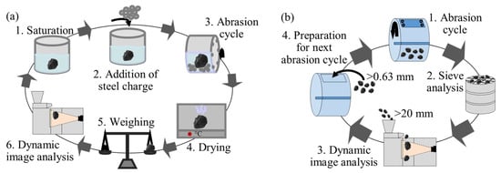
Figure 1.
Experimental methodology schemes: (a) abrasion in micro-Deval apparatus, (b) abrasion in Los Angeles machine.
Numerical data obtained from the experiment, namely mass loss values (mass change) and morphological parameter values (morphological change), were correlated with energy input (mechanical work). Because most of the correlations were not linear, data were linearized using log transformation or power transformation, depending on the best-fit function. Data were linearized so that linear regression could be performed and coefficients of determination (R2) between correlations could be compared. Additionally, Spearman’s rank correlation was performed between the previously mentioned data, to compare Spearman’s rank correlation coefficients (rho) between the parameters. The resulting values of shape parameters and mass losses were taken as a mean value of all tested particles (in case of single-clast abrasion tests), or as a mean value of all tested sample mixtures (in case of grain mixture abrasion tests).
2.1. Abrasion in Micro-Deval Apparatus
The micro-Deval test is a test for determining the resistance to abrasion and durability of a tested material. The most commonly used standards for the micro-Deval test are (1) ASTM D6928-17 “Resistance of Coarse Aggregate to Degradation by Abrasion in the Micro-Deval Apparatus” [26], (2) ASTM D7428-15 “Resistance of Fine Aggregate to Degradation by Abrasion in the Micro-Deval Apparatus” [27], and (3) BS EN 1097-1:2011 “Tests for mechanical and physical properties of aggregates, Part 1: Determination of resistance to wear (micro-Deval)” [28]. We applied a modified combination of standards. Instead of material with standard grading, we abraded each of the particles alone with steel charge in the drum (single clast abrasion). In total, nine dolomite particles were subjected to abrasion in the micro-Deval apparatus (MATEST A077) (Figure 2). A particle was submerged in 2.0 L of water at room temperature inside the micro-Deval drum to saturate for at least one hour before the abrasion cycle. After the saturation, 5.0 kg of steel charge was added (standard steel balls with 10 mm diameter—MATEST A078-11N). The drum filling was on average 56.3%, including steel balls, water, and rock particles, throughout the whole test. The mass loss after each cycle was relatively low and did not considerably affect the filling of the drum. The abrasion cycles had different durations, starting from shorter ones. Altogether, 15 consecutive cycles were applied, with a cumulative abrading time of 930 min. The durations of the consecutive cycles were (in order): 10, 10, 10, 30, 30, 30, 60, 60, 60, 90, 90, 90, 120, 120, 120 min. Abrasion was applied at 100 rpm. For each consecutive abrasion cycle, only the principal particle was kept—if any chipping occurred, the small fragments were not taken into consideration for further observation. Between each abrasion cycle, particles were oven dried to a constant mass at 105 °C and weighed to determine mass loss. Additionally, in between abrasion cycles, we analysed each particle in the dynamic image analyser Microtrac Camsizer XL to obtain morphological parameter values.
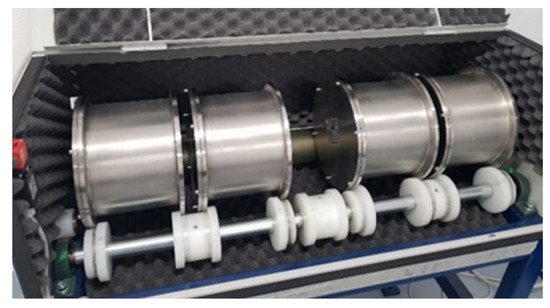
Figure 2.
Micro-Deval apparatus.
2.2. Abrasion in Los Angeles Machine
The Los Angeles abrasion test is a test for the determination of mineral aggregate degradation resulting from a combination of impact and abrasion. Material testing in the Los Angeles machine is standardised and described in (1) ASTM C535-16 “Resistance to Degradation of Large-Size Coarse Aggregate by Abrasion and Impact in the Los Angeles Machine” [29], (2) ASTM C131/C131M-14 “Resistance to Degradation of Small-Size Coarse Aggregate by Abrasion and Impact in the Los Angeles Machine” [30], and (3) BS EN 1097-2:2010 “Tests for Mechanical and Physical Properties of Aggregates, Part 2: Methods for the Determination of Resistance to Fragmentation” [31]. We applied the modified test procedure for abrasion tests in the Los Angeles machine. Three samples of particle mixtures (for three test repetitions), of the same grade as the particles abraded in the micro-Deval, were selected. Each sample weighed about 2.0 kg in total. Particles were subjected to abrasion in the Los Angeles machine in a dry condition and without the presence of steel balls so that the material did not crush too fast, which allowed us to track its morphological changes more precisely. Without the steel balls, the material only abrades itself. The Los Angeles machine used in the experiments was a standard machine (MATEST A075N) (Figure 3). The drum filling was 0.35% for the first cycle. Five consecutive cycles of abrasion were carried out on each sample. Cumulatively, particles were subjected to 1500 rotations (about 47 min in total). Durations of individual cycles at the rotational speed of 31–33 rpm were (in order): 160, 160, 180, 500, and 500 rotations (≈5, 5, 5, 15, 15 min). After each cycle, the material coarser than 4.0 mm was manually sieved (using 63, 50, 45, 40, 37.5, 31.5, 25, 20, 16, 14, 12.5, 10, 8, 6.3, and 4 mm sieves) to minimise any additional chipping and loss of material. The portion of the material finer than the 4.0 mm sieve was sieved in an electromagnetic sieve shaker (Haver and Boecker EML 450 digital plus) using 2.0, 1.7, 1.6, 1.0, 0.63, and 0.063 mm sieves. Material passing through the 0.63 mm sieve was considered as the mass loss of the mixture. The sieve size of 0.63 mm (630 µm) represents the coarse sand lower boundary sieve size [32]. This size was selected because sediment particles in the range between 0.63 and 0.063 mm can often be found in a suspended load along the -0.063 fraction [33,34]. Additionally, when dry sieving such fine fractions, a considerable portion of undersized particles tends to stay on the upper sieve. After the sieving, it could be seen that the mesh of the 0.063 mm sieve sometimes got clogged (almost cemented) so that finer particles could not pass through. The other factor preventing a complete passing of the finer particles was that due to vibrations of the sieve shaker, the smallest particles floated in a similar manner as when the drum lid is opened. It should also be mentioned that a small portion of the material was lost in the form of dust when opening the drum cover after an abrasion cycle, through clogging inside of the mill between the lifter and the curved surface, during the sample handling, etc. Material coarser than a 20 mm sieve was analysed in the dynamic image analyser. Smaller particles’ shapes were not analysed due to the high possibility of material getting lost during the analysis.
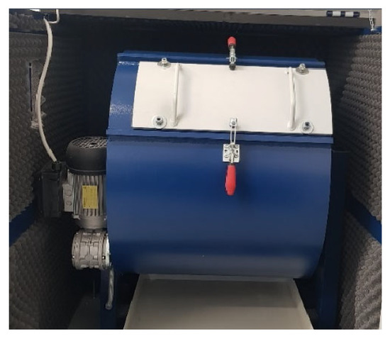
Figure 3.
Los Angeles machine.
2.3. Dynamic Image Analysis
Image analysis methods can be divided into two main groups, namely static (2D) and dynamic (3D). Dynamic methods are further divided into real 3D and quasi-3D. Dynamic image analysis methods are described in ISO 13322-2:2021 “Particle Size Analysis—Image Analysis Methods—Part 2: Dynamic Image Analysis Methods” [35]. Recently, as dynamic image analysis has been shown to be useful and convenient for particle analysis, it was adopted in numerous studies, such as Buckland et al. [36], Guo et al. [37], Li and Iskander [38], etc. Visual techniques for morphological analysis are extensively discussed in Wang et al. [4]. We used a Microtrac Camsizer XL (the operating scheme is presented in Figure 4), which is a quasi-3D dynamic image analyser used for particle characterization. The quasi-3D analysis results in 3D data obtained from a series of 2D images taken from different angles of an analysed object. Input material (particles) can range from 160 µm to 135 mm. As the material enters the machine, in its measuring area, the high-speed camera captures (~150 frames per second) the particle from different angles during its tumbling. We repeated the analysis two to three times, depending on the breakage tendency of the analysed material. If it seemed that the material could break during the impact after free fall, the measurements were stopped after two repetitions. For single-clast analysis, we aligned the particles’ a and b axes, and a transversal between a and b axes to the measurement feed direction, in an attempt to capture each particle from as many angles as possible. When analysing particle mixtures, the particles were not aligned in any specific orientation.
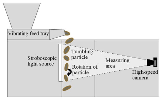
Figure 4.
Dynamic image analyser—Microtrac Camsizer XL operating scheme.
The software accompanying Microtrac Camsizer XL, PartAn 3D, calculates 33 3D size and shape parameters based on a sequence of images. We selected three parameters to trace the morphological changes of clasts, addressing shape and texture. The parameter “sphericity” (SPH) was selected to describe the particles’ form. It presents particles’ proximity to a perfect sphere, with values between 0 and 1 (a perfect sphere has a sphericity value of 1). It is calculated as the ratio between the area equivalent diameter (Da—calculated according to area A) and the equivalent perimeter diameter (Dp—calculated according to perimeter PERIM) (Equation (1)). The parameter “angularity” (ANG) was selected to describe the roundness/angularity aspect of the particles’ shapes. The parameter “angularity” was calculated according to Equation (2). Particles’ outlines were described by a polygon with n sides. The angle at each vortex was measured and the changes in angles were grouped into intervals of 10 degrees, with the value e being the starting value of each interval. P(e) is the probability that the change in angle has a value between e and e + 10. More angular particles had higher values (up to 180) and those that were more rounded had lower values (up to 0) of the “angularity” parameter. The calculation of ANG value is described in detail in Rao et al. [39] and Wang et al. [3]. The parameter “convexity” (CONV) was selected to describe the surface roughness or surface texture of particles. It was calculated as a ratio between the convex hull perimeter (PERIMCHULL) and the perimeter of the particle (PERIM) (Equation (3)). Convexity values are between 0 and 1, where 1 represents a perfectly smooth particle (a particle with an aligned perimeter and convex hull perimeter).
2.4. Abrasion Energy Input (Mechanical Work) and Power Estimation
The mechanical work done by the machines was estimated theoretically. It was also attempted to calculate the mechanical work from the power draw measurements. The effective net power draw was determined as the difference between the measured idling (no load) power draw of the machines and the power draw of the filled machines (with charge). This estimation was determined according to the assumption that the total power draw (P) is a sum of the net (effective) power draw (PNET), used for the comminution process, and the idling/no load power draw (PNL) (Equation (4)).
The power draw was measured using the energy consumption meter “VOLTCRAFT SEM6000”. This consumption meter measures the power, voltage, current, and frequency that are feeding a machine. When measuring power draw, the measurements started after the shift from star to delta transformation, meaning that the beginning power tends to be higher to start the initial motion of the machine. The mechanical work (energy) estimated for the abrasion machines (both micro-Deval and Los Angeles) was used for initiating particle motion, sound, temperature rise, abrasion, etc. That is why the estimated energy/mechanical work was taken into consideration as the energy/mechanical work to which a particle was subjected. In the abrasion machines, energy levels were considered to stay constant throughout the whole cycle.
The mechanical work (energy) used by both machines was also approximated theoretically. The theoretical calculation was simplified as described below (Equations (5)–(8)). For the micro-Deval apparatus, mechanical work was considered to be a result of the rotational kinetic energy (Ek) of the charge (including steel charge and a rock particle) inside the drum. For the calculation, all of the charge (water, steel balls, and rock particle) was considered as a whole, with an equally distributed mass. Buoyancy was neglected. It was assumed that there is no friction between the steel balls, and between the steel balls and the drum lining. Also, due to the absence of friction, the material was assumed to be rolling around the lowest point of the drum’s cross section.
where: W—mechanical work (J); Wrot—mechanical work introduced by rotation (J); Ek—kinetic energy (J); Δϕ—angular displacement (-);
where: I—moment of inertia (of charge) (kg/m2); ω—angular velocity (rad/s);
where: m—mass (of the charge) (kg); rm—distance from the centre of the drum cross section to the centre of mass of charge (m);
where: Δd—linear displacement (on the perimeter of the drum cross section) (m); r—radius of the drum’s cross section (m).
For the Los Angeles machine, the mechanical work was considered to be a result of the kinetic energy of the impact when a material drops to the toe of a drum, and the rotational kinetic energy of the charge inside the drum (Equations (9)–(12)). Due to the low filling of the drum (0.35% in first cycle, up to 0.28% in fifth cycle), it was taken into consideration that all of the material inside of the drum was lifted by the lifter/shelf and was carried on it for half of the rotation until it reached the highest point of the drum’s cross section (shoulder), when it dropped and impacted the toe of the drum. For the other half of the rotation, until it was collected again by the lifter, the material was under the influence of rotational kinetic energy.
where: Wimp—mechanical work introduced by impact (J);
where: Ek2—kinetic energy of charge at the toe of the drum (J); Ek1—kinetic energy of charge at the shoulder of the drum (J); Ep2—potential energy of the charge at the toe of the drum (J); Ep1—potential energy at the shoulder of the charge (J); m—mass of the charge (kg); g—gravitational acceleration (m/s2); h—height of the fall (m).
Rotational mechanical work (Wrot) was calculated the same way as for the micro-Deval.
The power of each machine was estimated according to Equation (13), namely as the work (introduced energy) of one revolution per the time of one revolution.
where: P—power of machine (W); Wrev—work of one revolution (J); trev—time needed for one revolution of a drum (s).
3. Results and Discussion
According to the steps shown in the Materials and Methods section, the mechanical work for the micro-Deval was approximated to be ~3.4 J per one revolution of the drum. In the Los Angeles machine, it was approximated to be ~17.8 J per one revolution of the drum, on average, in the first cycle (13.6 J accounting for impact mechanical work and 4.2 J for rotational mechanical work). In contrast to the micro-Deval apparatus, in the Los Angeles machine, the mechanical work considerably dropped with the mass loss, reaching ~14.4 J per rotation on average in the fifth cycle. This calculated mechanical work seems to be lower than the one calculated for the micro-Deval machine by Czinder et al. [40]. The difference probably occurred, firstly, because of the higher material content in the mill, and secondly because of the different assumptions made about the charge motions. In the mentioned study, the radius considered for the moment of inertia calculation was higher, and was calculated based on the charge distribution typical for a centrifuging charge motion. This might have led to the overestimation of mechanical work. The energy-related results, along with the main characteristics of both machines, are summarised in Table 1.

Table 1.
Main characteristics of the machines and power estimates. (D—inner diameter of the drum, L—inner length of the drum, ω—rotational speed of the drum, Mean m0—mean initial mass of the sample, Filling—filled portion of the drum, P0—power of the machine in the first cycle, ∑E—cumulative introduced energy, ∑t—cumulative time of abrasion (sum of all cycles’ duration), ∑Rev—cumulative number of revolutions).
We managed to measure the power difference between the idling power and the net power for the micro-Deval apparatus (Figure 5a). For the Los Angeles, the two curves overlapped (Figure 5b), and it was not possible to measure the power difference. This could be caused by the fact that during the Los Angeles experiments, the drum filling was lower than 1%, and the power draw needed for movements of such a small mass of charge/material was negligible when compared to the mass of the empty steel drum. The measured mechanical work in the micro-Deval was found to be 9.8 Watts (J/s) per drum. When recalculated to mechanical work per one revolution of drum, this equals 5.8 J. The theoretically estimated work represents only about 60% of the measured one for the micro-Deval apparatus. A part of this difference can be attributed to the power losses in bearings and gears, noise and heat generation, etc. [41]. In order to be able to compare the machines, theoretically derived energies (Equations (5)–(13)) were used for later processing and discussion.
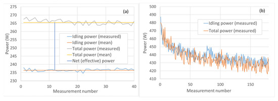
Figure 5.
Power draw measurements results for (a) micro-Deval abrasion tests; (b) Los Angeles abrasion tests.
3.1. Mass
Mass loss (or wear) of material was strongly correlated (R2 = 0.99) with the amount of energy introduced (mechanical work) to the material. However, the same amount of introduced energy in two different machines did not result in a similar amount of wear (Figure 6). This was expected, given the power (energy introduction rate) differences of the two systems (in Watts (J/s)). If comparing the two machines, we can say that, in given conditions, the micro-Deval is a low-energy machine with an energy introduction rate (power) of 5.7 J/s. On the other hand, the Los Angeles machine is a high-energy machine with an energy introduction rate (power) of around 9.5 J/s in the first cycle and 7.7 J/s in the fifth cycle. Power decreased with cycles due to the considerable mass loss, which was absent in experiments in the micro-Deval. The Los Angeles machine in the setup used had between 35% and 67% more power than the micro-Deval, resulting in an almost 10 times higher mass loss (for the same introduced energy). Surely, the selected sieve size determining the mass loss fraction influenced the results of the Los Angeles tests. However, if the selected size of 0.63 mm (as described in the section “Abrasion in Los Angeles Machine”) was replaced by a larger one, e.g., 1.0 mm, the mass loss values increased by only between 0.7% and 1.3% per cycle (known from the sieve analysis). This accounts for about 50% of the standard deviation (between three tested samples) of the mass loss results on the 0.63 sieve.
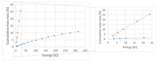
Figure 6.
Input energy of abrasion tests—cumulative mass loss of material plot (from micro-Deval test marked blue, from Los Angeles test marked orange).
Comparable results were found in annular flume experiments, described in Cassel et al. [2]. In that study, mean abrasion rates were found to be higher at higher flows—resulting in higher pebble velocities. Similarly, it was found that in degradation tests with variable rotational speeds, the wear of material increased with an increase in the rotational speeds of tumbling machines (for tests in the Slake durability apparatus and micro-Deval machine). Dias Filho et al. [42] explained that this increase in rotational speeds represents an increase in energy in the environment. If the rotational speed of the machine is increased, in the same experimental setting, it contributes to the greater power of the system. Similar conclusions can be drawn from the results found in a study by Brachaniec [43]. In a series of tumbling experiments, the increased rotational speeds resulted in higher mass loss of the samples. With the sample mixtures of the same properties, this could be attributed to the higher energies resulting from the increased speed. Additionally, in a series of micro-Deval and Los Angeles tests presented by Trotta et al. [44], Los Angeles tests resulted in higher mass loss compared to the micro-Deval mass loss for all of the lithotypes tested. In a study comparing aggregate properties, Czinder and Török [45] found no link between Los Angeles and micro-Deval values.
If the mass loss was brought down to the travelling distances (without knowing the real travelling distances), which are often determined as 60% of the circumference of the mill multiplied by the number of rotations (e.g., [46,47]), we yet again observed two very different results for the two machines used, with the same ratios, as when relating mass loss to energy. One of the possible solutions might be to introduce a coefficient related to the power of the system to the abrasion loss equations. By transforming mass loss (%) to “specific mass loss” (Equation (14)), we could obtain two almost overlapping curves. To transform mass loss data to specific mass loss (i.e., mass loss per power per unit mass), we had to multiply the values of the mass loss by coefficient (P*m0)−1 (Equation (15)). Both the filling and dimensions of a mill (any tumbling drum) have an impact on its power, which can also be seen in the theoretical equations for the power and introduced energy (mechanical work) estimation (section “Abrasion Energy Input (Mechanical Work) and Power Estimation”). Specific mass loss (mass loss per unit of mass per power) data, obtained from both tests, and energy inputs were highly correlated, with R2 = 0.99 (p-value < 0.01) (according to a linear correlation of linearized, log-transformed data) and RHO = 0.99 (p-value < 0.01) (according to Spearman rank correlation). Obvious discordance appeared in the last Los Angeles cycle data. This might have been caused by the handling of the material—exaggerated mass loss due to the additional loss of the material, as described in the sections “Abrasion in Micro-Deval Apparatus” and “Abrasion in Los Angeles Machine”. However, if the power decrease was disregarded, that is, if mass loss was considered constant throughout the whole abrasion process (all cycles) in both machines, the datasets overlap slightly better (Figure 7a), although the general function fitted to both datasets did not considerably change. If we observed only the energy input scope with data from both machines (up to about 30 kJ), the same could be noted. The curve fitted to such data (Figure 7b) (with available energy input data for both tests) follows Equation (16). Similar approaches, with expressing comminution using various machine or process properties (e.g., specific power), are often used in mineral processing, for mill scaling. An example of such an approach can be found in Yahyaei et al. [48], where mass loss was normalised by “surface specific comminution energy” to be able to compare the grinding rates obtained by mills with different dimensions, filling, and power.
where: MLS—specific mass loss (%/(kg*J)); ML—mass loss (%); E—input energy (mechanical work); CML—mass loss coefficient; P—power (W (J/s)); m0—initial mass of the sample material (kg).
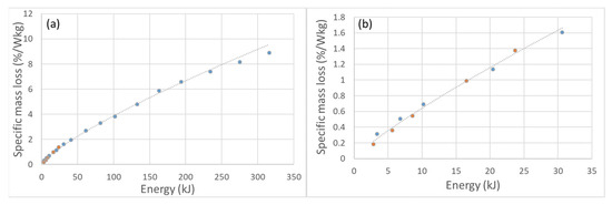
Figure 7.
Transformed mass loss data plot of input energy—“specific mass loss” for both machines combined (data from micro-Deval tests marked blue, data from Los Angeles tests marked orange): (a) all data, (b) for the energy input scope with data from both machines.
Equation (20) was derived (by steps shown in Equations (17)–(19)) from the relation expressed in Equation (16), which was based on experimental data obtained in both micro-Deval and Los Angeles tests, for the input energy scope with available data for both tests. This notation of the relation between the residual mass and the energy inputs is in a form most commonly used for describing the wear of particles (the mass form of Sternberg’s law [8]. This relation is presented by fitting curve in Figure 8a. Figure 8b shows measured vs. predicted residual mass (in kg) values (y = 1x).
where: RM%—residual mass (%); mres—residual mass (kg).

Figure 8.
(a) Graphical representation of Equation (19) (data from micro-Deval tests are marked blue, and from the Los Angeles tests marked orange), (b) measured vs. calculated residual mass using Equation (20). One should note that in Figure (b), there are multiple points marked blue (representing data from micro-Deval tests), but they are close to each other.
When the expression from Equation (19) was plotted against the input energies, the original relation between the relative residual mass (mres/m0) and the energy input for each process was obtained (Figure 9), with the general expression following Equation (21) and also Equation (22). Exponent c is an abrasion coefficient, which is lithology specific, but also seems to be process (power conditions) dependent. The coefficient c obtained was 0.012/kJ and 0.0006/kJ for high-energy abrasion (in Los Angeles) and low-energy abrasion (in micro-Deval), respectively.
where: c—abrasion coefficient (−/kJ).
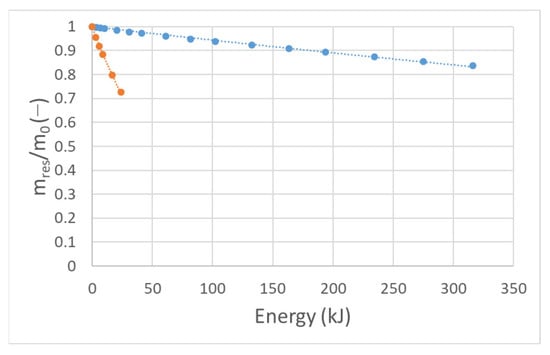
Figure 9.
Relation between relative residual mass and input energy for both abrasion tests (results from micro-Deval tests marked blue, results from Los Angeles tests marked orange).
Wear rates, expressed as mass loss per introduced energy (mechanical work) (%/kJ), decreased with energy applied (mechanical work) to abraded material—that is, with each abrasion cycle. Generally, high-energy abrasion wear rates were much higher than low-energy abrasion rates. This can be seen in Figure 10a. Additionally, the change in wear rate is related to the particle shape, but shows the strongest correlation with the angularity (R2 = 0.88 for micro-Deval, and R2 = 0.90 for Los Angeles) (Figure 10b). This can be explained by the angular particles experiencing chipping of angular parts faster, contributing to greater mass loss. When roundness increases, there is a smaller presence of angular parts to be chipped off, and a particle is abraded at a slower rate—observed already by Schoklitsch [49] in his laboratory experiments in a tumbling mill using angular and rounded clasts. This is also in accordance with the observations of Yao et al. [46], who found that angular particles lose significantly more mass in contrast to rounded ones in a series of two-cycle abrasion tests in a micro-Deval. They studied the influence of fluid in a tumbling test and found greater mass losses of material abraded in water compared to the material abraded in dry conditions. This is definitely a difference between the here-presented dry experiments in the Los Angeles apparatus and the wet experiments in the micro-Deval apparatus, respectively. In this study, the influence of water was acknowledged and taken into account by its mass that contributes to the overall energy (and power) of the abrasion in each setup. Paixão and Fortunato [50], in two-cycle abrasion tests, found higher wear rates in the first cycle when compared to the second abrasion cycle. Similar observations were made by Manga et al. [51]. Deiros Quintanilla et al. [52] explained the reduction of wear rates by the asperities becoming rounder, resulting in higher resistance to wear. In contrast, during the low-energy abrasion, wear rates decreased rapidly in the beginning of the abrasion (in the first several cycles). Later on, the wear rate began to change (lower) at a slower rate. It should be noted that in the 10th and 11th cycles, one of the particles abraded in single-clast abrasion experiments (micro-Deval) experienced a major breakage, resulting in a considerable fragment being broken off. Consequently, this event contributed to the jump in wear rate values in the 10th and 11th cycles.
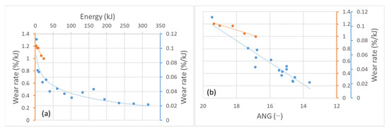
Figure 10.
Wear rates from micro-Deval tests (marked blue) and Los Angeles tests (marked orange) in relation to (a) input energy; (b) angularity.
For the abrasion tests of particle mixtures in the Los Angeles machine, mean grain sizes (d50), coefficients of uniformity (CU), and coefficients of curvature (CC) were determined from particle size distribution curves of the tested material (shown in Figure 11). The initial (at t0) mean median grain size d50 was 51 mm, the mean coefficient of uniformity CU = 1.26, and the mean coefficient of curvature CC = 0.99. This describes the material as evenly graded [53]. During the first ~5 min of rotation (160 rotations), the initial particle size distribution experienced a fast change. During the further abrasion, the change in size slowed down. After the first abrasion cycle in the Los Angeles machine, the mean median grain size dropped to 37.03 mm, the CU changed to 5.88, and the CC to 2.50. By the end of the fifth cycle (1500 rotations, ~47 min), the mean d50 diminished to 23.37 mm and the CC to 14.64, whereas the CU grew until the end of the 4th cycle (to 47.97) and then started getting smaller again, reaching 45.86. The particle size distribution curve migrated from poorly graded to well graded, until the fifth cycle. According to Erichsen et al. [25], well-graded distribution curves of material after the Los Angeles test indicate domination of breakage, whereas the domination of abrasion results in poorly graded or gap-graded distribution curves. After the fifth cycle, most of the biggest particles were broken, and the material started shifting towards even gradation again. This can also be seen from the particle size distribution curves (Figure 11). From the initial (t0) narrow and vertical distribution curve, the curve became wider and more horizontal. After the fifth cycle, the curve started narrowing and becoming more vertical again, which shows that the material particles were all becoming smaller and narrower in range. Particle size distributions of one of the samples tested in the Los Angeles machine (LA1) for all of the abrasion cycles and the initial state are presented in Figure 11.
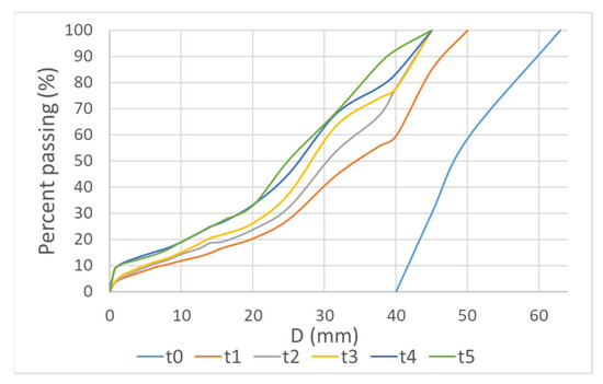
Figure 11.
Evolution of particle size distribution of material (one of the samples) abraded in Los Angeles machine in each abrasion cycle.
3.2. Morphology
During the low-energy abrasion, particles’ form evolution was much slower, and they were, in general, preserved. Particles abraded at the lower energy levels mainly preserved the initial shape class during the whole abrasion applied to them. This can be seen in Figure 12a, which presents particles abraded in the micro-Deval apparatus in their initial form (marked with squares) and after 15 abrasion cycles (marked with circles). Other studies investigating shape (form) evolution according to Zingg’s classification described similar observations [46,50,52]. On the other hand, during the higher energy abrasion, form evolution happened fast. Particles dispersed on Zingg’s diagram after each abrasion cycle regardless of their previous form (shape class) due to breakage and the creation of new particles (Figure 12b). After the fifth cycle, many particles (coarser than 20 mm) migrated towards the equant end member of the classification (53.85%) if compared to the initial phase (33.33% equant particles) and after the first cycle (29.63% equant particles). Following the equant end member in the count was the prolate end member (26.92% after the fifth cycle). Figure 12b shows particles from one of the mixtures abraded in the Los Angeles machine (LA1) in their initial form (marked with squares), after one abrasion cycle (marked with Xs), and after five abrasion cycles (marked with circles). The form changes can also be seen in the pictures of the material abraded in the experiment (Figure 13).
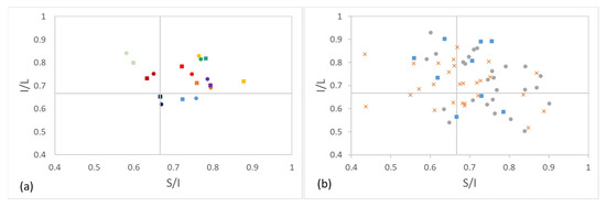
Figure 12.
Particle form classification according to Zingg [5]. (a) Particles’ form before testing in micro-Deval apparatus (marked with squares) and after 15 cycles of abrasion in micro-Deval apparatus (marked with circles) A square and a circle of the same colour represent the same particle. (b) Particles’ form before testing in Los Angeles machine (marked with squares), after first cycle of abrasion (marked with Xs), and after fifth cycle of abrasion in Los Angeles machine (marked with circles).
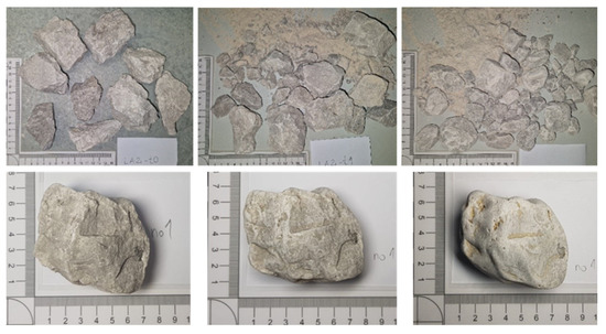
Figure 13.
Particles from the abrasion tests. Particles from tests in Los Angeles machine (at initial state, after first cycle, and after fifth cycle) in the first row. Particle from tests in micro-Deval apparatus (at initial state, after fifth cycle, and after fifteenth cycle) in the second row.
Regarding the roundness and angularity aspect of the particle shape, it experienced the biggest relative (percentual) change during both of the experimental setups. Therefore, we can argue that the biggest change occurs in the aspect of rounding of material. With respect to mass loss, during the more energy-intensive abrasion process, particles experienced a slightly higher change in sphericity and convexity, whereas angularity experienced a higher relative change during the low-energy abrasion. On the other hand, with respect to total introduced energy, particles experienced considerably higher shape changes during more energy-intensive abrasion in the sphericity and convexity parameters, whereas angularity showed a similar change for both low-energy and high-energy abrasion. This can be attributed to the breakage that occurs during the high-energy abrasion, which results in the propagation of sharp edges and diminution of rounding. All of the relative (percentual) changes with respect to mass loss (Figure 14, Figure 15 and Figure 16) show a similar trend, but with respect to the total energy (work), high-energy abrasion shows a much higher change in sphericity and convexity, with a steeper slope. The absolute value of the convexity parameter (surface texture aspect of particle shape) is higher for the low-energy abrasion at the same mass loss values, implying that a particle becomes smoother faster if abraded slower. A similar aggregate behaviour was observed by Kamani and Ajalloeian [54], where surface-texture-wise tested aggregates kept an unchanged texture after the Los Angeles (standard) test, but the surface became significantly smoother after the micro-Deval (standard) test. Additionally, a considerably higher decrease in angularity after the micro-Deval test (when compared to the Los Angeles test) was found. This can again be explained by the absence of breakage. Absolute shape parameters’ values in relation to mass loss in general indicate a faster approach to smooth round shapes for particles abraded in the micro-Deval apparatus—low-energy abrasion. A general increase in roundness and smoothness of abraded particles was observed by Yao et al. [46], Paixão and Fortunato [50], Manga et al. [51], and Deiros Quintanilla et al. [52]. Figure 14, Figure 15 and Figure 16 show a relative change of shape parameters in relation to input energy and mass loss, as well as an absolute value change. Morphological parameter data obtained from low-energy abrasion tests in the micro-Deval apparatus are marked blue, while the data obtained from high-energy abrasion in the Los Angeles machine are marked orange. The considerable differences in the morphological evolution of particles resulting from different energy levels in experimental abrasion indicate the possibility of using particle morphology to identify the transportation conditions they have experienced.
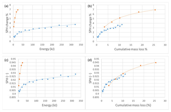
Figure 14.
Sphericity changes of abraded material. Data for micro-Deval abrasion tests are marked blue and data for Los Angeles tests are marked orange—(a) relation between input energy and sphericity change; (b) relation between cumulative mass loss and sphericity change; (c) relation between input energy and sphericity value; (d) relation between cumulative mass loss and sphericity value.

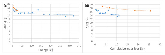
Figure 15.
Angularity changes of abraded material. Data for micro-Deval abrasion tests are marked blue and data for Los Angeles tests are marked orange—(a) relation between input energy and angularity change; (b) relation between cumulative mass loss and angularity change; (c) relation between input energy and angularity value; (d) relation between cumulative mass loss and angularity value.
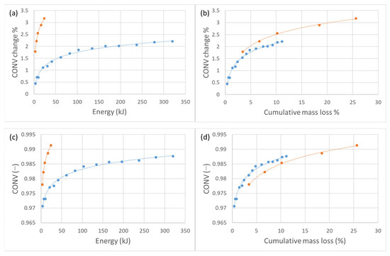
Figure 16.
Convexity changes of abraded material. Data for micro-Deval abrasion tests are marked blue and data for Los Angeles tests are marked orange—(a) relation between input energy and convexity change; (b) relation between cumulative mass loss and convexity change; (c) relation between input energy and convexity value; (d) relation between cumulative mass loss and convexity value.
The absolute angularity value after the first cycle of abrasion in the Los Angeles machine dropped for coarser particles, but the angularity of newly produced (by breakage) particles was higher than that of initial particles. On the other hand, particles in coarser size classes experienced a lowering of angularity. This can be interpreted as an indication that large particles, as they approach roundness, lose parts that become more angular. With further abrasion, all of the particles experienced a lowering of angularity, with coarser particles being more angular than finer ones in each cycle (Figure 17). This observation is applied only to those particles that were investigated for morphological changes (i.e., coarser than the 20 mm sieve).
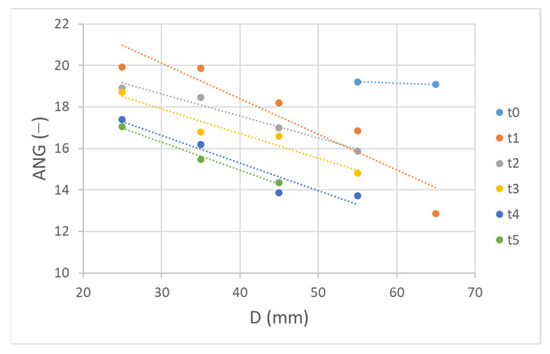
Figure 17.
Distribution of angularity values according to size class before tests and after each abrasion cycle in Los Angeles machine, for particles coarser than 20 mm.
4. Conclusions
In this work, the standardised equipment used in rock mechanics for aggregate testing was used for abrasion experiments to evaluate the mass loss and morphological evolution of abraded particles. In fluvial abrasion research experiments, wear of material is usually calculated according to the travelling distance of the abraded material. Here, we assessed abrasion according to the input energies (mechanical work) and powers of two different experimental abrasion setups, one in the micro-Deval apparatus and one in the Los Angeles machine. High-energy abrasion (in the Los Angeles machine) resulted in higher abrasion rates than the ones obtained with low-energy abrasion (in the micro-Deval machine). In general, the investigated particles showed the greatest change in the roundness shape aspect, with a greater change during the low-energy abrasion.
Our study results suggest that the key to scaling different tumbling abrasion experiments one to another is in the power and energy applied to the material by the chosen setups. By introducing the “mass loss coefficient”, the measured experimental setup specific mass loss data can be transformed into “specific mass loss”—a percentual loss of mass per initial mass of the material per power unit. Specific mass loss values are then comparable for the two experimental setups and show a good agreement in relation to input energy. This approach might even be applied to natural streams by taking a fraction of fluvial stream power into consideration, which will be a subject of further investigations—as well as for other fields of applied studies investigating abrasion using tumbling experiments (as discussed in the introduction section). Additionally, because of the novelty of the mass loss coefficient, it should be further investigated in abrasion experiments using different materials and further experimental setups, as well as in rigorous analyses of the experimental abrasion results available in the literature. Last but not least, the different morphological changes resulting from the two experimental setups point to the potential of tracking morphological changes in material for the identification of energy-related conditions of the transportation environment.
Author Contributions
Conceptualization: T.K., M.M.; Methodology: T.K., M.M.; Validation: T.K.; Formal Analysis: T.K.; Investigation: T.K., K.L.; Resources: M.M.; Data Curation: T.K.; Writing—Original Draft: T.K.; Writing—Review and Editing: M.M., K.L., T.K.; Visualization: T.K.; Supervision: M.M.; Funding Acquisition: M.M. All authors have read and agreed to the published version of the manuscript.
Funding
This research was funded by the Slovenian Research Agency, PhD grant of the first author, and research core funding No. P2-0180. The APC was funded by the Slovenian Research Agency.
Institutional Review Board Statement
Not applicable.
Informed Consent Statement
Not applicable.
Data Availability Statement
The data presented in this study are available on request from the corresponding author.
Conflicts of Interest
The authors declare no conflict of interest. The funders had no role in the design of the study; in the collection, analyses, or interpretations of data; in the writing of the manuscript; or in the decision to publish the results.
References
- Blott, S.J.; Pye, K. Particle Shape: A Review and New Methods of Characterization and Classification. Sedimentology 2008, 55, 31–63. [Google Scholar] [CrossRef]
- Cassel, M.; Piégay, H.; Lavé, J.; Vaudor, L.; Hadmoko Sri, D.; Wibiwo Budi, S.; Lavigne, F. Evaluating a 2D Image-Based Computerized Approach for Measuring Riverine Pebble Roundness. Geomorphology 2018, 311, 143–157. [Google Scholar] [CrossRef]
- Wang, L.; Sun, W.; Tutumluer, E.; Druta, C. Evaluation of Aggregate Imaging Techniques for Quantification of Morphological Characteristics. Transp. Res. Rec. 2013, 2335, 39–49. [Google Scholar] [CrossRef]
- Wang, L.; Yao, Y.; Li, J.; Tao, Y.; Liu, K. Review of Visualization Technique and Its Application of Road Aggregates Based on Morphological Features. Appl. Sci. 2022, 12, 571. [Google Scholar] [CrossRef]
- Zingg, T. Beitrag Zur Schotteranalyse. Doctoral Dissertation; ETH Zurich: Zürich, Switzerland, 1935; pp. 39–140. [Google Scholar]
- Sneed, E.D.; Folk, R.L. Pebbles in the Lower Colorado River, Texas a Study in Particle Morphogenesis. J. Geol. 1958, 66, 114–150. [Google Scholar] [CrossRef]
- Krumbein, W.; Sloss, L. Stratigraphy and Sedimentation; W.H.Freeman and Co.: San Francisco, CA, USA, 1963. [Google Scholar]
- Sternberg, H. Untersuchungen Uber Langen-und Querprofil Geschiebefuhrender Flusse. Z. Bauwes 1875, 25, 486–506. [Google Scholar]
- Brachaniec, T. Relationship between the Abrasion of Tektite Clasts and Their Host Sedimentary Facies, Pleistocene, Sw Poland. Ann. Soc. Geol. Pol. 2019, 89, 83–90. [Google Scholar] [CrossRef]
- Mikoš, M.; Jaeggi, M.N.R. Experiments on Motion of Sediment Mixtures in a Tumbling Mill to Study Fluvial Abrasion. J. Hydraul. Res. 1995, 33, 751–772. [Google Scholar] [CrossRef]
- Lewin, J.; Brewer, P.A. Laboratory Simulation of Clast Abrasion. Earth Surf. Process. Landf. 2002, 27, 145–164. [Google Scholar] [CrossRef]
- Novák-Szabó, T.; Sipos, A.Á.; Shaw, S.; Bertoni, D.; Pozzebon, A.; Grottoli, E.; Sarti, G.; Ciavola, P.; Domokos, G.; Jerolmack, D.J. Universal Characteristics of Particle Shape Evolution by Bed-Load Chipping. Sci. Adv. 2018, 4, 1–12. [Google Scholar] [CrossRef]
- Attal, M.; Lavé, J. Pebble Abrasion during Fluvial Transport: Experimental Results and Implications for the Evolution of the Sediment Load along Rivers. J. Geophys. Res. Earth Surf. 2009, 114, F04023. [Google Scholar] [CrossRef]
- Wu, J.; Hou, Y.; Wang, L.; Guo, M.; Meng, L.; Xiong, H. Analysis of Coarse Aggregate Performance Based on the Modified Micro Deval Abrasion Test. Int. J. Pavement Res. Technol. 2018, 11, 185–194. [Google Scholar] [CrossRef]
- Bian, X.; Shi, K.; Li, W.; Luo, X.; Tutumluer, E.; Chen, Y. Quantification of Railway Ballast Degradation by Abrasion Testing and Computer-Aided Morphology Analysis. J. Mater. Civ. Eng. 2021, 33, 04020411. [Google Scholar] [CrossRef]
- Maue, A.D.; Levy, J.S.; Burr, D.M.; Matulka, P.R.; Nathan, E. Rapid Rounding of Icy Clasts during Simulated Fluvial Transport in the Titan Tumbler. Icarus 2022, 375, 114831. [Google Scholar] [CrossRef]
- Bak, E.N.; Larsen, M.G.; Jensen, S.K.; Nørnberg, P.; Moeller, R.; Finster, K. Wind-Driven Saltation: An Overlooked Challenge for Life on Mars. Astrobiology 2019, 19, 497–505. [Google Scholar] [CrossRef]
- Kueppers, U.; Putz, C.; Spieler, O.; Dingwell, D.B. Abrasion in Pyroclastic Density Currents: Insights from Tumbling Experiments. Phys. Chem. Earth 2012, 45–46, 33–39. [Google Scholar] [CrossRef]
- Hornby, A.J.; Kueppers, U.; Maurer, B.; Poetsch, C.; Dingwell, D.B. Experimental Constraints on Volcanic Ash Generation and Clast Morphometrics in Pyroclastic Density Currents and Granular Flow. Volcanica 2020, 3, 263–283. [Google Scholar] [CrossRef]
- Frontini, R.; Fernández-Jalvo, Y.; Pesquero Fernández, M.D.; Vecchi, R.J.; Bayón, C. Abrasion in Archaeological Fish Bones from Sand Dunes. An Experimental Approach. Archaeol. Anthropol. Sci. 2019, 11, 4891–4907. [Google Scholar] [CrossRef]
- Thompson, C.E.L.; Ball, S.; Thompson, T.J.U.; Gowland, R. The Abrasion of Modern and Archaeological Bones by Mobile Sediments: The Importance of Transport Modes. J. Archaeol. Sci. 2011, 38, 784–793. [Google Scholar] [CrossRef]
- Chu, W.; Thompson, C.; Hosfield, R. Micro-Abrasion of Flint Artifacts by Mobile Sediments: A Taphonomic Approach. Archaeol. Anthropol. Sci. 2015, 7, 3–11. [Google Scholar] [CrossRef]
- BS EN 1097-6:2013; Tests for Mechanical and Physical Properties of Aggregates—Part 6: Determination of Particle Density and Water Absorption. British Standards Institution: London, UK, 2013.
- Strzałkowski, P.; Kazmierczak, U. Wear and Fragmentation Resistance of Mineral Aggregates—A Review of Micro-Deval and Los Angeles Tests. Materials 2021, 14, 5456. [Google Scholar] [CrossRef] [PubMed]
- Erichsen, E.; Ulvik, A.; Sævik, K. Mechanical Degradation of Aggregate by the Los Angeles-, the Micro-Deval-and the Nordic Test Methods. Rock Mech. Rock Eng. 2011, 44, 333–337. [Google Scholar] [CrossRef]
- ASTM D6928-17; Resistance of Coarse Aggregate to Degradation by Abrasion in the Micro-Deval Apparatus. ASTM: West Conshohocken, PA, USA, 2017.
- ASTM D7428-15; Resistance of Fine Aggregate to Degradation by Abrasion in the Micro-Deval Apparatus. ASTM: West Conshohocken, PA, USA, 2015.
- BS EN 1097-1:2011; Tests for Mechanical and Physical Properties of Aggregates, Part 1: Determination of Resistance to Wear (Micro-Deval). British Standards Institution: London, UK, 2011.
- ASTM C535-16; Resistance to Degradation of Large-Size Coarse Aggregate by Abrasion and Impact in the Los Angeles Machine. ASTM: West Conshohocken, PA, USA, 2016.
- ASTM C131/C131M-14; Resistance to Degradation of Small-Size Coarse Aggregate by Abrasion and Impact in the Los Angeles Machine. ASTM: West Conshohocken, PA, USA, 2014.
- BS EN 1097-2:2010; Tests for Mechanical and Physical Properties of Aggregates. Part 2: Methods for the Determination of Resistance to Fragmentation. British Standards Institution: London, UK, 2010; 34p.
- ISO 14688-1:2017; Geotechnical Investigation and Testing—Identification and Classification of Soil—Part 1: Identification and Description. ISO: Geneva, Switzerland, 2017.
- Walling, D.E.; Moorehead, P.W. The Particle Size Characteristics of Fluvial Suspended Sediment: An Overview. Hydrobiologia 1989, 176–177, 125–149. [Google Scholar] [CrossRef]
- Singh, M.; Singh, I.B.; Müller, G. Sediment Characteristics and Transportation Dynamics of the Ganga River. Geomorphology 2007, 86, 144–175. [Google Scholar] [CrossRef]
- ISO 13322-2:2021; Particle Size Analysis—Image Analysis Methods—Part 2: Dynamic Image Analysis Methods. ISO: Geneva, Switzerland, 2021.
- Buckland, H.M.; Saxby, J.; Roche, M.; Meredith, P.; Rust, A.C.; Cashman, K.V.; Engwell, S.L. Measuring the Size of Non-Spherical Particles and the Implications for Grain Size Analysis in Volcanology. J. Volcanol. Geotherm. Res. 2021, 415, 107257. [Google Scholar] [CrossRef]
- Guo, Y.; Markine, V.; Song, J.; Jing, G. Ballast Degradation: Effect of Particle Size and Shape Using Los Angeles Abrasion Test and Image Analysis. Constr. Build. Mater. 2018, 169, 414–424. [Google Scholar] [CrossRef]
- Li, L.; Iskander, M. Evaluation of Roundness Parameters in Use for Sand. J. Geotech. Geoenviron. Eng. 2021, 147, 04021081. [Google Scholar] [CrossRef]
- Rao, C.; Tutumluer, E.; Kim, I.T. Quantification of Coarse Aggregate Angularity Based on Image Analysis. Transp. Res. Rec. 2002, 1787, 117–124. [Google Scholar] [CrossRef]
- Czinder, B.; Vásárhelyi, B.; Török, Á. Long-Term Abrasion of Rocks Assessed by Micro-Deval Tests and Estimation of the Abrasion Process of Rock Types Based on Strength Parameters. Eng. Geol. 2021, 282, 105996. [Google Scholar] [CrossRef]
- Gupta, A.; Yan, D. Mineral Processing Design and Operations Roll Crushers; Elsevier: Amsterdam, The Netherlands, 2016; ISBN 9780444635891. [Google Scholar]
- Dias Filho, J.L.E.; Pereira Santos, V.G.; Cesar, P.; Maia, A.; De Castro Xaviera, G. Study of Relationship between Wear Tests on Rocks by Slake Durability, Micro-Deval and Los Angeles Abrasion Tests. In Proceedings of the ISRM Regional Symposium-8th South American Congress on Rock Mechanics SACRM, Buenos Aires, Argentina, 15–18 November 2015; pp. 225–230. [Google Scholar] [CrossRef]
- Brachaniec, T. Susceptibility of Various Tektite Types to Fluvial Abrasion. Geol. Q. 2019, 63, 150–161. [Google Scholar] [CrossRef]
- Trotta, R.P.; Barroso, E.V.; da Motta, L.M.G. Migmatitic Gneiss Aggregates: Compositional, Mechanical, and Morphological Responses to Innate Heterogeneity. Eng. Geol. 2021, 283, 106002. [Google Scholar] [CrossRef]
- Czinder, B.; Török, Á. Long-Term Durability Tests of Andesite Aggregates from Hungary. Cent. Eur. Geol. 2017, 60, 333–343. [Google Scholar] [CrossRef]
- Yao, T.; Yang, H.; Lourenço, S.D.N.; Baudet, B.A.; Kwok, F.C.Y. Multi-Scale Particle Morphology Evolution in Rotating Drum Tests: Role of Particle Shape and Pore Fluid. Eng. Geol. 2022, 303, 106669. [Google Scholar] [CrossRef]
- Caballero, L.; Sarocchi, D.; Borselli, L.; Cárdenas, A.I. Particle Interaction inside Debris Flows: Evidence through Experimental Data and Quantitative Clast Shape Analysis. J. Volcanol. Geotherm. Res. 2012, 231–232, 12–23. [Google Scholar] [CrossRef]
- Yahyaei, M.; Weerasekara, N.S.; Powell, M.S. Characterisation of Superficial Breakage Using Multi-Size Pilot Mills. Miner. Eng. 2015, 81, 71–78. [Google Scholar] [CrossRef]
- Schoklitsch, A. Über Die Verkleinerung Der Geschiebe in Flussläufen. Akad. Wiss. Wien 1933, IIa, 343–366. [Google Scholar]
- Paixão, A.; Fortunato, E. Abrasion Evolution of Steel Furnace Slag Aggregate for Railway Ballast: 3D Morphology Analysis of Scanned Particles by Close-Range Photogrammetry. Constr. Build. Mater. 2021, 267, 121225. [Google Scholar] [CrossRef]
- Manga, M.; Patel, A.; Dufek, J. Rounding of Pumice Clasts during Transport: Field Measurements and Laboratory Studies. Bull. Volcanol. 2011, 73, 321–333. [Google Scholar] [CrossRef]
- Deiros Quintanilla, I.; Combe, G.; Emeriault, F.; Voivret, C.; Ferellec, J.F. X-Ray CT Analysis of the Evolution of Ballast Grain Morphology along a Micro-Deval Test: Key Role of the Asperity Scale. Granul. Matter 2019, 21, 30. [Google Scholar] [CrossRef]
- ISO 14688-2:2017; Geotechnical Investigation and Testing—Identification and Classification of Soil—Part 2: Principles for a Classification. ISO: Geneva, Switzerland, 2017.
- Kamani, M.; Ajalloeian, R. Investigation of the Changes in Aggregate Morphology during Different Aggregate Abrasion/Degradation Tests Using Image Analysis. Constr. Build. Mater. 2022, 314, 125614. [Google Scholar] [CrossRef]
Disclaimer/Publisher’s Note: The statements, opinions and data contained in all publications are solely those of the individual author(s) and contributor(s) and not of MDPI and/or the editor(s). MDPI and/or the editor(s) disclaim responsibility for any injury to people or property resulting from any ideas, methods, instructions or products referred to in the content. |
© 2023 by the authors. Licensee MDPI, Basel, Switzerland. This article is an open access article distributed under the terms and conditions of the Creative Commons Attribution (CC BY) license (https://creativecommons.org/licenses/by/4.0/).