Communication

High-Performance Wearable Bi2Te3-Based Thermoelectric Generator

1
State Key Laboratory of Advanced Technology for Materials Synthesis and Processing, Wuhan University of Technology, Wuhan 430070, China
2
Nanostructure Research Center, Wuhan University of Technology, Wuhan 430070, China
3
Research Center for Materials Genome Engineering, Wuhan University of Technology, Wuhan 430070, China
*
Authors to whom correspondence should be addressed.
Appl. Sci. 2023, 13(10), 5971; https://doi.org/10.3390/app13105971
Submission received: 22 April 2023 / Revised: 6 May 2023 / Accepted: 10 May 2023 / Published: 12 May 2023
(This article belongs to the Special Issue Electrical Systems: Design, Optimization and Application)

Abstract

:
Wearable thermoelectric generators (w-TEGs) convert thermal energy into electrical energy to realize self-powering of intelligent electronic devices, thus reducing the burden of battery replacement and charging, and improving the usage time and efficiency of electronic devices. Through finite element simulation, this study successfully designed high-performance thermoelectric generator and made it into wearable thermoelectric module by adopting “rigid device—flexible connection” method. It was found that higher convective heat transfer coefficient (h) on cold-end leads to larger effective temperature difference (ΔTeff) and better power generation performance of device in typical wearable scenario. Meanwhile, at same h on the cold-end, longer TE leg length leads to larger ΔTeff established at both ends of device, larger device output power (Pout) and open-circuit voltage (Uoc). However, when the h increases to a certain level, optimization effect of increasing TE leg length on device power generation performance will gradually diminish. For devices with fixed temperature difference between two ends, longer TE leg length leads to higher resistance of TEGs, resulting in lower device Pout but slight increase in Uoc. Finally, sixteen 16 × 4 × 2 mm2 TEGs (L = 1.38 mm, W = 0.6 mm) and two modules were fabricated and tested. At hot end temperature Th = 33 °C and cold end temperature Tc = 30 °C, the actual maximum Pout of the TEG was about 0.2 mW, and the actual maximum Pout of the TEG module was about 1.602 mW, which is highly consistent with the simulated value. This work brings great convenience to research and development of wearable thermoelectric modules and provides new, environmentally friendly and efficient power solution for wearable devices.

1. Introduction

With the improvement of people’s living standards, wearable devices have become an indispensable part of people’s lives, including smart watches, smart glasses, smart wristbands, etc. [1,2,3,4]. However, the battery capacity and energy density of wearable devices limit their service life and stability, which has become a major obstacle limiting their development and application [5,6,7,8]. Therefore, it has become a global consensus to develop and apply green energy technologies [9,10].
As an emerging green energy technology, thermoelectric (TE) power generation can harvest energy from temperature differences in the environment to drive electronic devices by using the Seebeck effect (Figure 1A), which effectively solves problems such as the insufficient battery capacity of traditional wearable devices [11,12,13]. A thermoelectric generator (TEG) is a solid-state device that contains no mechanical moving parts, thus requiring no maintenance, high reliability, and noiseless operation, while being lightweight, compact, and taking up little space [14,15,16,17]. Furthermore, wearable thermoelectric generators (w-TEGs) have been studied by many scholars [18,19,20,21,22].
Fan et al. [23] used a simple cutting and gluing method to fabricate a w-TEG containing 48 pairs of P/N thermoelectric legs without a ceramic substrate. The w-TEG can be easily attached to the human body, and the maximum power density of the w-TEG was 7.9 μWcm−2 and 43.6 μWcm−2 under windless and normal walking conditions, respectively. Liu et al. [24] used a radiative cooling coating on the w-TEG. Compared with the original device without the radiation cooling coating, its output power was increased by 128% in an exposed environment and 96% in a non-exposed environment. Its output power density was about 5.5 μWcm−2 when the room temperature was 295 K. Zhang et al. [4] prepared a flexible micro-TEG with high power density and light mass using a pulse plating technique and effectively reduced the contact resistance between the thermoelectric leg and the electrode by adjusting the plating conditions. The optimized flexible micro-TEG had a maximum area power density and mass power density as high as 14.3 mWcm−2 and 189 mWg−1, respectively, at a temperature difference of 29.9 °C. Liang et al. [6] designed a non-planar π-type flexible TEG with passive radiation cooling and a wave-shaped heat sink instead of a metal heat sink. The output power density of 12.36 μWcm−2 and voltage density of 4.04 mVcm−2 at 23 °C when worn on the human body is sufficient to drive some microwatt and sub-microwatt wearable electronics.
W-TEGs can be flexible using three approaches: fabrication of thin-film type TEGs, TEGs using conductive polymers as thermoelectric units, and TEGs using flexible organic substrates connected to rigid inorganic thermoelectric units [25,26,27,28,29,30,31]. However, thin-film type thermoelectric units have difficulty in establishing a large enough temperature difference, and their power generation performance is usually poor [32,33,34,35]. Although conductive polymers are flexible, and thus fit the skin well, their low power factor largely limits the power generation performance of the corresponding TEG [36,37,38,39]. While the TE properties of inorganic semiconductors are excellent, by using flexible connections, the resulting TEGs not only have high Pout, but also good flexibility [40,41,42,43,44]. By using rigid thermoelectric legs in the flexible design of the “strap”, such a TEG can generate enough power and still fit well on the human body.
In the current context of environmental pollution and energy shortages, the research and application of w-TEGs is of great significance [45,46,47,48,49]. This study aims to improve the power generation performance of thermoelectric devices in a wearable scenario. The device structure is optimized using finite element simulation, and the overall wearability of the module is achieved by the “rigid device—flexible connection” approach. The effect of convective heat transfer coefficient h on the effective temperature difference of the device in a typical wearable scenario is explored, and the TE leg length L is optimized. This study shows the direction for the performance optimization of Bi2Te3-based thermoelectric generators in wearable scenarios.

2. Experimental Methods

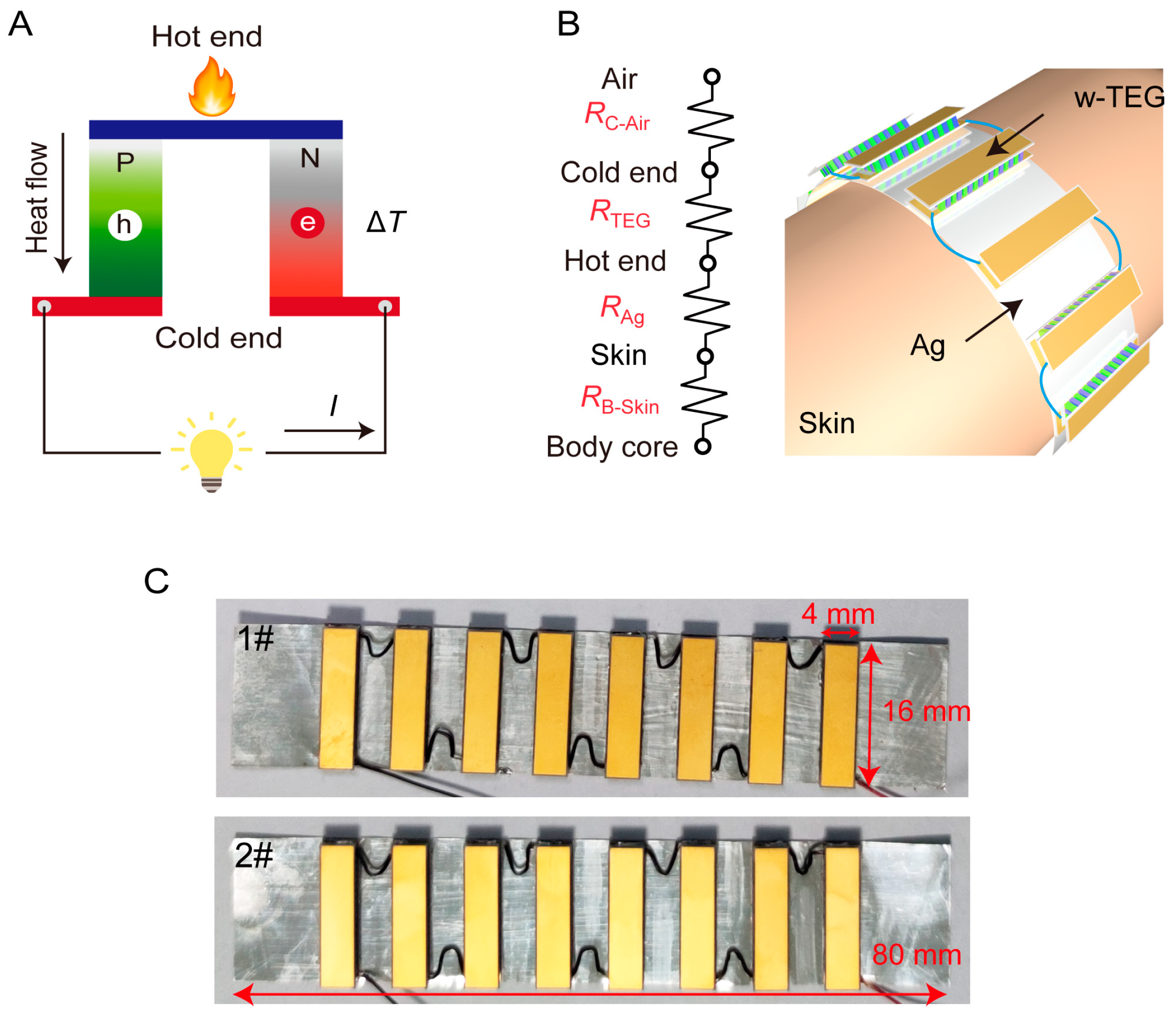
2.1. Finite Element Modeling

In different environments, the human body maintains a stable temperature through its thermoregulatory system. This process involves changes in the thermal resistance of human skin [50]. In this study, we used a simplified human thermoregulation model for finite element simulation and introduced virtual thermal resistance to represent heat transfer properties in the skin. When the ambient temperature is lower than 25 °C, the thermal resistance of skin remains constant; however, when the ambient temperature exceeds 25 °C, thermal resistance suddenly decreases [51,52,53].
The model consists of three parts: skin, flexible substrate, and thermoelectric devices. The equivalent thermal resistance of these parts is shown in Figure 1B and the finite element model is shown in Figure S1. In this paper, we adopt the “rigid device—flexible connection” approach. Specifically, we connect eight thermoelectric devices with equal size of 16 × 4 mm2 in series to form a module and solder them on a silver foil to realize the flexible design (Figure 1B). The thermoelectric materials are p-type Bi0.5Sb1.5Te3 and n-type Bi2Te2.7Se0.3 (Table S1). The electrode and substrate materials are Cu and AlN ceramics, respectively, and the solder is a Au–Sn alloy. The thermal conductivity and resistivity of these materials are shown in Table S2. All simulations in this study were performed using ANSYS Workbench finite element software, and each process was repeated until convergence.

2.2. Setting Boundary Conditions

The corresponding thermodynamic relationships of heat flux and current density are as follows:
κ T + J 2 σ T J [ α T T + α ) T = 0
J = 0
J = σ V + α T
q = α T J κ T  
where the Seebeck coefficient (α), thermal conductivity (κ), and electrical conductivity (σ) are the intrinsic properties of TE materials, T is the absolute temperature, and V is the electrostatic potential. The vectors J and q represent the current density and heat flux density, respectively.
To refine the model and simplify calculations, the following reasonable assumptions are proposed:
(1)
All surfaces (except the hot and cold ends) are considered to be well thermally insulated;
(2)
The simulation does not consider the heat sink (if any), and its effects are considered in thermal boundary conditions;
(3)
The electric contact resistance (Rec) and thermal contact resistance (Rtc) between electrodes and TE legs are both taken into account in the finite element model (Figure S2), which is set to 3.0 µΩ·cm2 and 1 × 10⁻⁵ m2K/W. The other interfacial contact thermal resistances are neglected;
(4)
The nonlinear temperature dependence of α, κ, and σ are considered;
(5)
Thomson effect is neglected.

2.3. w-TEG Module Fabrication

According to the designed connection circuit, copper electrodes (0.025 mm) were patterned on the AlN substrate (0.25 mm) using an adhesive-free calendering method. The copper electrode surface was gold-plated to improve welding reliability and, thus, reduce the Rec. The p-type Bi0.5Sb1.5Te3 and n-type Bi2Te2.7Se0.3 bulk materials were cut into cuboid-shaped legs, of which the upper and lower surfaces were pre-plated with nickel (~5 μm) and gold (~100 nm) film. Then, the sandwich structure composed of “AlN substrate/TE legs/AlN substrate” was welded together with AuSn solder to make micro thermoelectric devices. The module was formed by connecting eight thermoelectric devices in series with copper wires and soldering them to a 0.1 mm thick silver foil using AuSn solder to achieve a “rigid device—flexible connection”, as shown in Figure 1C. The detailed preparation process can also be checked in our previous article [5,8,17,53].

3. Results and Discussion

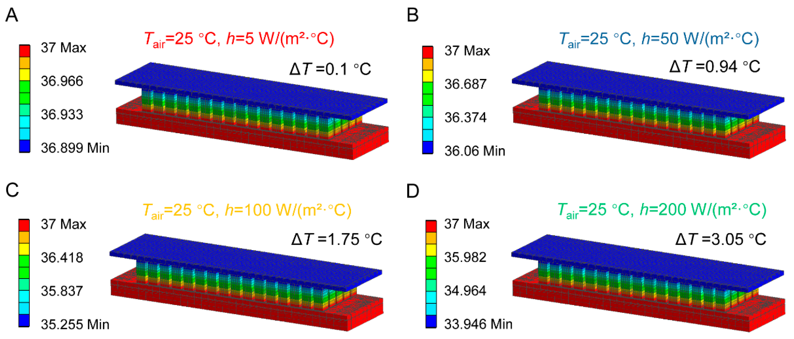
3.1. Effective Temperature Difference of TEGs under Different Convective Heat Transfer Coefficients

Figure 2 shows the temperature field of the TE devices with convective heat transfer coefficients at the cold end of 5, 50, 100, and 200 W/(m2 °C), respectively. When the ambient temperature Tair is 25 °C, the maximum device temperature Tmax is 37 °C, while the minimum device temperature Tmin decreases with the increase in convective heat transfer coefficient. In a typical wearable scenario, the natural convection heat transfer coefficient of air is 5 W/(m2 °C), the minimum temperature Tmin of the device is 36.899 °C at this time, and the average temperature difference ΔT is 0.1 °C. In the case of forced convection heat transfer, the air convection heat transfer coefficient is 50 W/(m2 °C), the minimum temperature Tmin of the device is 36.06 °C, and the average temperature difference ΔT is 0.94 °C. When the convective heat transfer coefficient increases to 50 W/(m2 °C), the minimum temperature Tmin of the device is 35.255 °C and the average temperature difference ΔT is 1.75 °C. When the convective heat transfer coefficient increases to 200 W/(m2 °C), the minimum device temperature Tmin is 33.946 °C and the average temperature difference ΔT is 3.05 °C.
As shown in Figure 2, increasing convective heat transfer coefficient h at the cold end leads to an increase in temperature difference between two ends of the device, which provides guidance for optimizing power generation performance of the device in a wearable scenario.

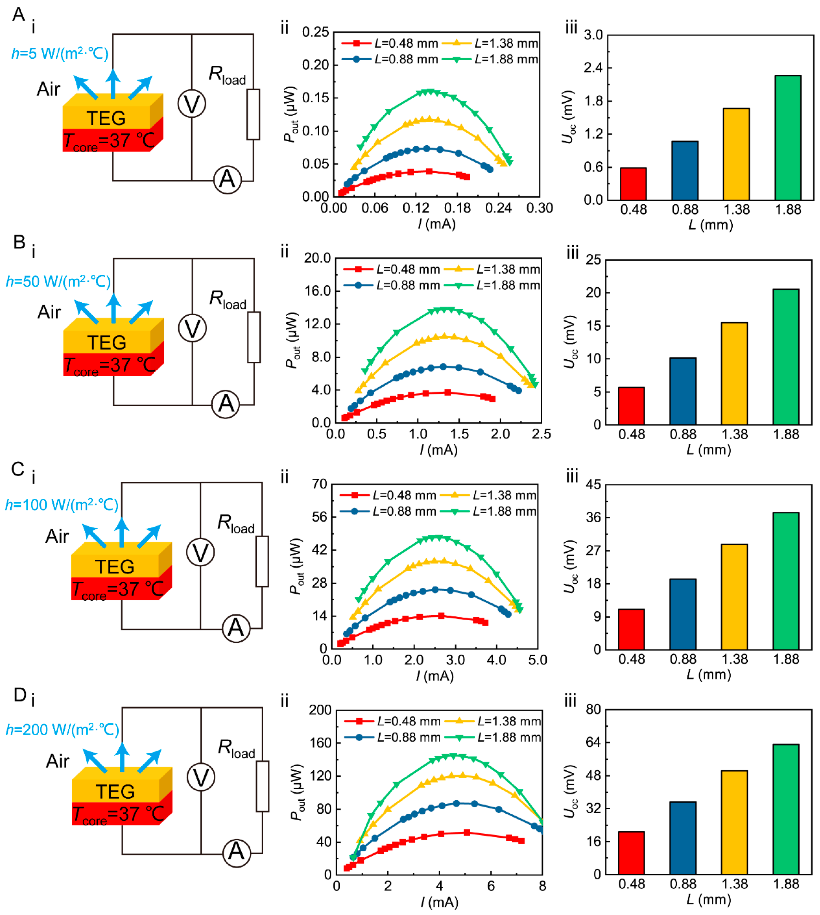
3.2. Power Generation Performance Optimization of TEGs under Different Convective Heat Transfer Coefficients

Figure 3 shows the Pout and Uoc of a TEG with different leg lengths under h = 5, 50, 100, and 200 W/(m2 °C) at the cold end. The results show that the Pout increases and then decreases as the current increases. Both the maximum Pout and Uoc increase gradually with the increase in h and TE leg length.
At h = 5 W/(m2 °C), the maximum Pout of the TEGs with leg length L of 0.48 mm, 0.88 mm, 1.38 mm, and 1.88 mm are 0.039 μW, 0.074 μW, 0.117 μW, and 0.161 μW, and the Uoc of the TEGs is 0.583 mV, 1.07 mV, 1.67 mV, and 2.26 mV, respectively (Figure 3A). The maximum Pout and Uoc of the TEG with a leg length of 1.88 mm are 4.1 and 3.9 times higher than those of the L = 0.48 mm TEG, respectively.
As the convective heat transfer coefficient h increases to 50 W/(m2 °C), the maximum output power Pout of the four TEGs is 3.71 μW, 6.85 μW, 10.5 μW, and 13.8 μW, and the open-circuit voltage Uoc of the devices is 5.67 mV, 10.2 mV, 15.5 mV, and 20.6 mV (Figure 3B), respectively. The maximum Pout and Uoc of the TEG with the longest TE leg are both about three~four times higher than those with the shortest TE leg. As the h increases to 100 W/(m2 °C), the maximum Pout of the TEGs is about 300 times higher than that at h = 5 W/(m2 °C) (Figure 3C). The Uoc of the TEGs is 16~19 times higher than that at h = 5 W/(m2 °C). As h increases to 200 W/(m2 °C) (Figure 3D), the maximum Pout of the TEGs is 900~1300 times higher than that at h = 5 W/(m2 °C) (Figure 3D). The Uoc of the TEGs is about 30 times higher than that at h = 5 W/(m2 °C), respectively.
It can be obviously seen from Figure 3 that, for TEGs with any leg length, the larger the h, the better the heat dissipation effect and the better the power generation performance of the device. For the same cold end convective heat transfer coefficient h, the longer the TE leg length L, the larger the effective temperature difference between the two ends of the device, and the larger output power and open-circuit voltage of the device.
However, as h increases, increasing L to optimize device power generation performance gradually becomes less effective. Therefore, in wearable scenarios, it is necessary to design a reasonable heat dissipation structure and select efficient heat dissipation materials to improve h at the cold end of the device. This will improve the ΔTeff and power generation performance of the device.

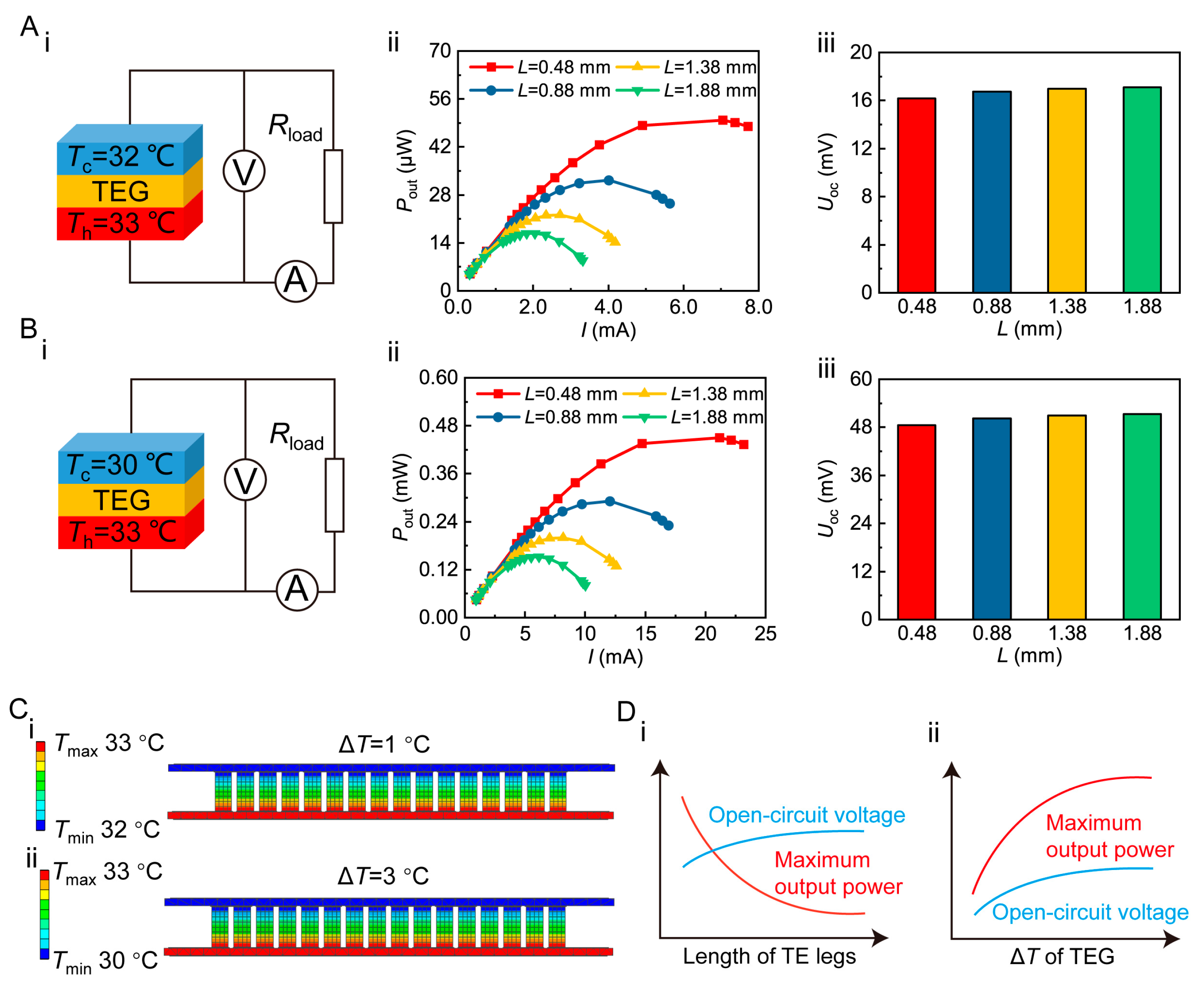
3.3. Power Generation Performance Optimization of TEGs under Fixed Temprature Difference Conditions

According to the results in Section 3.1, the ΔTeff between the two ends of the TEG ranges from 0.1 °C to 3.05 °C in a typical wearable scenario. Therefore, it is necessary to investigate how to optimize device power generation performance under fixed temperature difference conditions.
Figure 4 shows the Pout and Uoc of TEGs with different TE legs under a temperature difference ΔT of 1 °C and 3 °C. It is observed that the Pout increases and then decreases with the increase in current under these two different temperature differences, and the maximum Pout and Uoc increase gradually with temperature difference. It should be noted, however, that the maximum Pout decreases with increasing TE leg length.
At ΔT = 1 °C, the maximum Pout of devices with TE leg length L of 0.48 mm, 0.88 mm, 1.38 mm, and 1.88 mm is 49.9 μW, 32.3 μW, 22.2 μW, and 16.8 μW, and the Uoc is 16.2 mV, 16.7 mV, 17.0 mV, and 17.1 mV, respectively (Figure 4A). The maximum Pout of a device with a TE leg length of 1.88 mm is 66.3% lower than that of an L = 0.48 mm device. Meanwhile, the Uoc increases by 5.6%.
As ΔT increases to 3 °C, the maximum Pout of four TEGs with different TE leg lengths is 0.451 mW, 0.292 mW, 0.200 mW, and 0.152 mW; the Uoc is 48.5 mV, 50.2 mV, 50.9 mV, and 51.3 mV, respectively (Figure 4B). When the hot end temperature Th is 33 °C and cold end temperature Tc is 32 °C and 30 °C, the temperature field of the TEG can be displayed in Figure 4C.
According to Figure 4D, the TEG resistance gradually increases with the increase in TE leg length under a fixed temperature difference between two ends (Figure S3); the maximum Pout gradually decreases, but the Uoc slightly increases. In addition, the Seebeck effect of material is enhanced as the temperature difference between two ends increases, thus improving the power generation performance of a device.

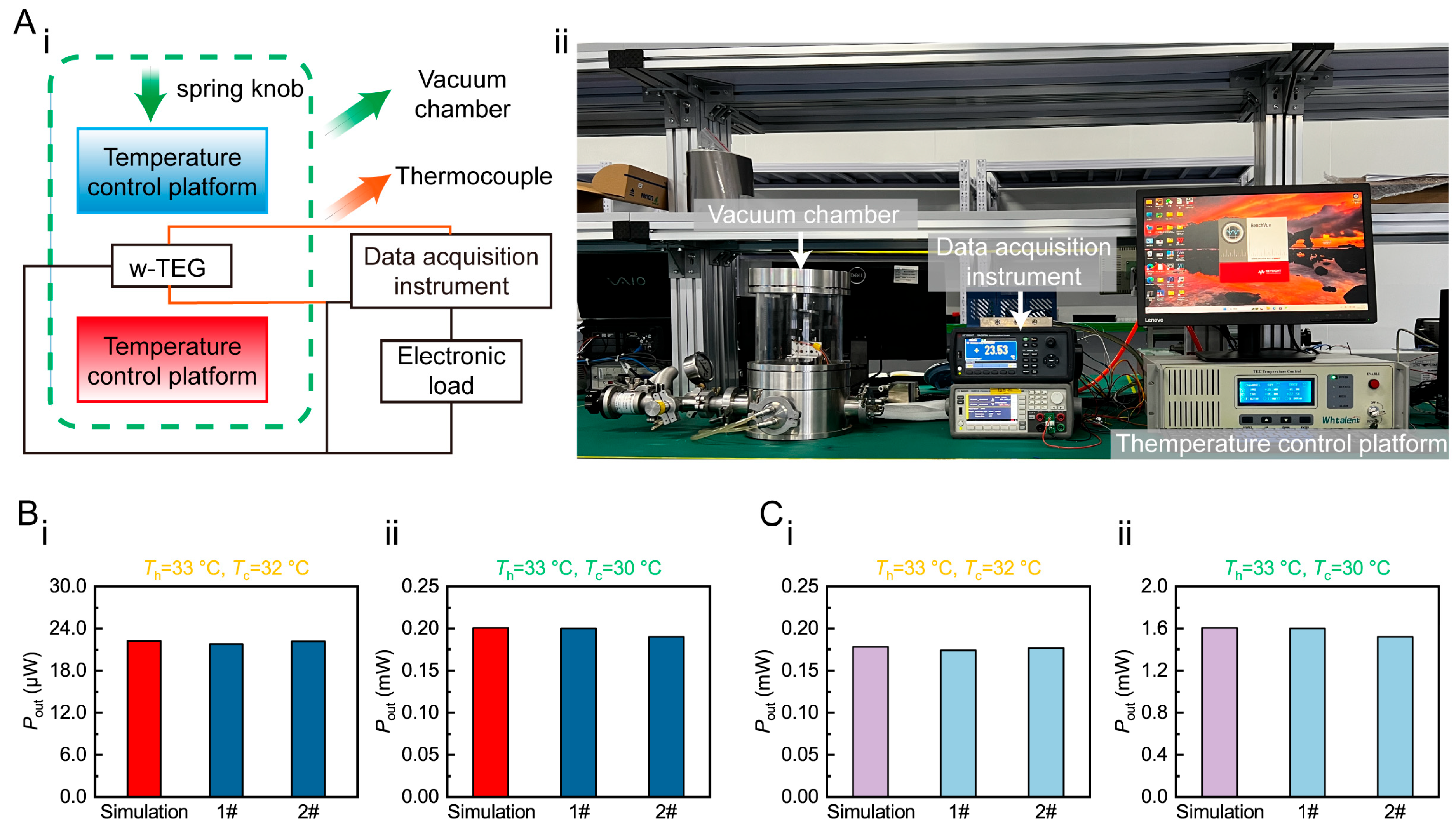
3.4. Power Generation Performance Verification of the TEG Module under Different Temprature Differences

Figure 5A shows the schematic and physical diagram of a self-designed test system for power generation performance of the TEG. The system consists of a temperature-controlled platform, data collector, load resistor, and computer. The w-TEG to be tested is placed between two temperature-controlled platforms. By adjusting spring-loaded knobs and applying thermal grease to contact surfaces, the w-TEG is in close contact with upper and lower temperature-controlled platforms to improve heat utilization. The w-TEG connects and drives loads with different resistances. The data collector records the output voltage U and current I, then the output power is calculated using P = UI. All tests are conducted in a vacuum chamber.
From Section 3.1 and Section 3.2, it can be seen that a longer length of TE leg leads to better power generation performance of a TEG in typical wearable scenarios. However, from industrial processing experience, the ratio of TE leg length to width, i.e., L/W, should not exceed three; otherwise, the TE leg will easily fracture and fail.
To verify the power generation performance of thermoelectric devices in accordance with simulated results, sixteen 16 × 4 × 2 mm2 TEGs (L = 1.38 mm, W = 0.6 mm) and two modules were fabricated and tested. At a hot end temperature of Th = 33 °C and a cold end temperature of Tc = 32 °C, the actual maximum Pout of 1# and 2# TEGs is 21.8 μW and 22.1 μW, respectively (Figure 5(Bi)), and the actual maximum Pout of 1# and 2# TEG modules is 0.174 mW and 0.177 mW, respectively (Figure 5(Bii)). Compared with the simulated value, the difference is only 2.3% and 0.6%. At a hot end temperature of Th = 33 °C and a cold end temperature of Tc = 30 °C, the actual maximum Pout of 1# and 2# TEGs is 0.2 mW and 0.19 mW, respectively (Figure 5(Ci)), and the actual maximum Pout of 1# and 2# TEG modules is 1.602 mW and 1.52 mW, respectively (Figure 5(Cii)), which is only 0.5% different from the simulated value. The above experimental results show that finite element simulation successfully guides the design of w-TEGs.

4. Conclusions

Through finite element simulation, this study successfully designed a high-performance thermoelectric generator (TEG) and made it into a wearable thermoelectric module by adopting the “rigid device—flexible connection” method. It was found that in typical wearable scenarios, a higher convective heat transfer coefficient (h) on the cold end leads to larger effective temperature difference (ΔTeff) and better power generation performance of the device. Meanwhile, at the same h on the cold end, longer TE leg length leads to larger ΔTeff established at both ends of device, larger device output power (Pout), and open-circuit voltage (Uoc). However, when the h increases to a certain level, the optimization effect of increasing TE leg length on device power generation performance will gradually diminish. For devices with a fixed temperature difference between two ends, longer TE leg length leads to higher resistance of TEGs, resulting in lower Pout but a slight increase in Uoc. Finally, sixteen 16 × 4 × 2 mm2 TEGs (L = 1.38 mm, W = 0.6 mm) and two modules were fabricated and tested. At hot end temperature Th = 33 °C and cold end temperature Tc = 30 °C, the actual maximum Pout of the TEG was about 0.2 mW, and the actual maximum Pout of the TEG module was about 1.602 mW, which is highly consistent with the simulated value.

Supplementary Materials

The following supporting information can be downloaded at: https://www.mdpi.com/article/10.3390/app13105971/s1, Figures S1 to S3, Table S1 to S2. The supporting information is available free of charge from the internet or from the authors.

Author Contributions

D.Y. and Y.Y. conceived the project; Y.X. (Yubing Xing), K.T. and Y.L. carried out the finite element simulation; Y.X. (Yubing Xing), D.Y., K.H., J.W., Y.X. (Yani Xiao), J.L. (Jianan Lyu) and J.L. (Junhao Li) prepared the TEGs and tested their output power generation performance; Y.X. (Yubing Xing), D.Y., P.Z. and Y.Y. analyzed the experimental data; Y.X. (Yubing Xing) and D.Y. co-wrote the manuscript. All authors have read and agreed to the published version of the manuscript.

Funding

This work was financially supported by the National Natural Science Foundation of China (52202289), the International Postdoctoral Exchange Fellowship Program (PC2022044), and the National Key Research and Development Program of China (2019YFA0704900).

Institutional Review Board Statement

Not applicable.

Informed Consent Statement

Not applicable.

Data Availability Statement

Not applicable.

Conflicts of Interest

The authors declare no conflict of interest.

References

  1. Yu, Y.; Zhu, W.; Zhou, J.; Guo, Z.; Liu, Y.; Deng, Y. Wearable Respiration Sensor for Continuous Healthcare Monitoring Using a Micro-Thermoelectric Generator with Rapid Response Time and Chip-Level Design. Adv. Mater. Technol. 2022, 7, 2101416. [Google Scholar] [CrossRef]
  2. Zou, Q.; Shang, H.; Huang, D.; Xie, B.; Zhang, L.; Wang, K.; Dong, H.; Li, C.; Gu, H.; Ding, F. Bi2Te3-based flexible thermoelectric generator for wearable electronics. Appl. Phys. Lett. 2022, 120, 023903. [Google Scholar] [CrossRef]
  3. Fan, W.; An, Z.; Liu, F.; Gao, Z.; Zhang, M.; Fu, C.; Zhu, T.; Liu, Q.; Zhao, X. High-Performance Stretchable Thermoelectric Generator for Self-Powered Wearable Electronics. Adv. Sci. 2023, 10, 2206397. [Google Scholar] [CrossRef] [PubMed]
  4. Zhang, J.; Zhang, W.; Wei, H.; Tang, J.; Li, D.; Xu, D. Flexible micro thermoelectric generators with high power density and light weight. Nano Energy 2023, 105, 108023. [Google Scholar] [CrossRef]
  5. Hu, K.; Yang, D.; Hui, Y.; Zhang, H.; Song, R.; Liu, Y.; Wang, J.; Wen, P.; He, D.; Liu, X.; et al. Optimized thermal design for excellent wearable thermoelectric generator. J. Mater. Chem. A 2022, 10, 24985–24994. [Google Scholar] [CrossRef]
  6. Liang, J.; Huang, M.; Zhang, X.; Wan, C. Structural design for wearable self-powered thermoelectric modules with efficient temperature difference utilization and high normalized maximum power density. Appl. Energy 2022, 327, 120067. [Google Scholar] [CrossRef]
  7. Shi, Y.; Lü, X.; Xiang, Q.; Li, J.; Shao, X.; Bao, W. Stretchable thermoelectric generator for wearable power source and temperature detection applications. Energy Convers. Manag. 2021, 253, 115167. [Google Scholar] [CrossRef]
  8. You, H.; Li, Z.; Shao, Y.; Yuan, X.; Liu, W.; Tang, H.; Zhang, Q.; Yan, Y.; Tang, X. Flexible Bi2Te3-based thermoelectric generator with an ultra-high power density. Appl. Therm. Eng. 2021, 202, 117818. [Google Scholar] [CrossRef]
  9. Hasan, M.N.; Nayan, N.; Nafea, M.; Muthalif, A.G.; Ali, M.S.M. Novel structural design of wearable thermoelectric generator with vertically oriented thermoelements. Energy 2022, 259, 125032. [Google Scholar] [CrossRef]
  10. He, X.; Gu, J.; Hao, Y.; Zheng, M.; Wang, L.; Yu, J.; Qin, X. Continuous manufacture of stretchable and integratable thermoelectric nanofiber yarn for human body energy harvesting and self-powered motion detection. Chem. Eng. J. 2022, 450, 137937. [Google Scholar] [CrossRef]
  11. He, W.; Zhang, G.; Zhang, X.; Ji, J.; Li, G.; Zhao, X. Recent development and application of thermoelectric generator and cooler. Appl. Energy 2015, 143, 1–25. [Google Scholar] [CrossRef]
  12. Twaha, S.; Zhu, J.; Yan, Y.; Li, B. A comprehensive review of thermoelectric technology: Materials, applications, modelling and performance improvement. Renew. Sustain. Energy Rev. 2016, 65, 698–726. [Google Scholar] [CrossRef]
  13. Champier, D. Thermoelectric generators: A review of applications. Energy Convers. Manag. 2017, 140, 167–181. [Google Scholar] [CrossRef]
  14. Zhang, T. Design and optimization considerations for thermoelectric devices. Energy Convers. Manag. 2016, 112, 404–412. [Google Scholar] [CrossRef]
  15. Nozariasbmarz, A.; Collins, H.; Dsouza, K.; Polash, M.H.; Hosseini, M.; Hyland, M.; Liu, J.; Malhotra, A.; Ortiz, F.M.; Mohaddes, F.; et al. Review of wearable thermoelectric energy harvesting: From body temperature to electronic systems. Appl. Energy 2019, 258, 114069. [Google Scholar] [CrossRef]
  16. Hasan, N.; Nafea, M.; Nayan, N.; Ali, M.S.M. Thermoelectric Generator: Materials and Applications in Wearable Health Monitoring Sensors and Internet of Things Devices. Adv. Mater. Technol. 2021, 7, 2101203. [Google Scholar] [CrossRef]
  17. Yuan, X.; Li, Z.; Shao, Y.; Yang, D.; Hu, K.; You, H.; Xu, Z.; Hua, S.; Liu, W.; Peng, P.; et al. Bi2Te3-based wearable thermoelectric generator with high power density: From structure design to application. J. Mater. Chem. C 2022, 10, 6456–6463. [Google Scholar] [CrossRef]
  18. Yan, Q.; Kanatzidis, M.G. High-performance thermoelectrics and challenges for practical devices. Nat. Mater. 2021, 21, 503–513. [Google Scholar] [CrossRef]
  19. Park, K.T.; Cho, Y.S.; Jeong, I.; Jang, D.; Cho, H.; Choi, Y.; Lee, T.; Ko, Y.; Choi, J.; Hong, S.Y.; et al. Highly Integrated, Wearable Carbon-Nanotube-Yarn-Based Thermoelectric Generators Achieved by Selective Inkjet-Printed Chemical Doping. Adv. Energy Mater. 2022, 12, 2200256. [Google Scholar] [CrossRef]
  20. Li, Y.; Shi, Y.; Wang, X.; Luo, D.; Yan, Y. Thermal and electrical contact resistances of thermoelectric generator: Experimental study and artificial neural network modelling. Appl. Therm. Eng. 2023, 225, 120154. [Google Scholar] [CrossRef]
  21. Pan, H.; Zhao, D. An improved model for performance predicting and optimization of wearable thermoelectric generators with radiative cooling. Energy Convers. Manag. 2023, 284, 116981. [Google Scholar] [CrossRef]
  22. Wu, B.; Wei, W.; Guo, Y.; Yip, W.H.; Tay, B.K.; Hou, C.; Zhang, Q.; Li, Y.; Wang, H. Stretchable thermoelectric generators with enhanced output by infrared reflection for wearable application. Chem. Eng. J. 2023, 453, 139749. [Google Scholar] [CrossRef]
  23. Fan, W.; Shen, Z.; Zhang, Q.; Liu, F.; Fu, C.; Zhu, T.; Zhao, X. High-Power-Density Wearable Thermoelectric Generators for Human Body Heat Harvesting. ACS Appl. Mater. Interfaces 2022, 14, 21224–21231. [Google Scholar] [CrossRef] [PubMed]
  24. Liu, Y.; Hou, S.; Wang, X.; Yin, L.; Wu, Z.; Wang, X.; Mao, J.; Sui, J.; Liu, X.; Zhang, Q.; et al. Passive Radiative Cooling Enables Improved Performance in Wearable Thermoelectric Generators. Small 2022, 18, 2106875. [Google Scholar] [CrossRef] [PubMed]
  25. Mytafides, C.K.; Tzounis, L.; Karalis, G.; Formanek, P.; Paipetis, A.S. High-Power All-Carbon Fully Printed and Wearable SWCNT-Based Organic Thermoelectric Generator. ACS Appl. Mater. Interfaces 2021, 13, 11151–11165. [Google Scholar] [CrossRef]
  26. Zheng, Y.; Han, X.; Yang, J.; Jing, Y.; Chen, X.; Li, Q.; Zhang, T.; Li, G.; Zhu, H.; Zhao, H.; et al. Durable, stretchable and washable inorganic-based woven thermoelectric textiles for power generation and solid-state cooling. Energy Environ. Sci. 2022, 15, 2374–2385. [Google Scholar] [CrossRef]
  27. Chen, K.; Wang, L.; Luo, Z.; Xu, X.; Li, Y.; Liu, S.; Zhao, Q. Flexible Thermoelectrics Based on Plastic Inorganic Semiconductors. Adv. Mater. Technol. 2023, 202300189. [Google Scholar] [CrossRef]
  28. Shen, Y.; Han, X.; Zhang, P.; Chen, X.; Liu, D.; Yang, X.; Zheng, X.; Chen, H.; Zhang, K.; Zhang, T. Review on Fiber-Based Thermoelectrics: Materials, Devices, and Textiles. Adv. Fiber Mater. 2023, 1–36. [Google Scholar] [CrossRef]
  29. Tian, Y.; Ren, G.; Zhou, Z.; Wei, Z.; Fang, W.; Song, J.; Shi, Y.; Chen, X.; Lin, Y. Optimizing output performance and parasitic depletion of Bi2Te3-based thermoelectric generators by using a high-density approach. J. Mater. Chem. A 2023, 11, 9464–9473. [Google Scholar] [CrossRef]
  30. Wu, M.; Li, J.; Liu, Y.; Wang, Z.; Wei, P.; Zhao, W.; Cai, K. High Thermoelectric Performance and Ultrahigh Flexibility Ag2S1–xSex film on a Nylon Membrane. ACS Appl. Mater. Interfaces 2023, 15, 8415–8423. [Google Scholar] [CrossRef]
  31. Zhu, P.; Luo, X.; Lin, X.; Qiu, Z.; Chen, R.; Wang, X.; Wang, Y.; Deng, Y.; Mao, Y. A self-healable, recyclable, and flexible thermoelectric device for wearable energy harvesting and personal thermal management. Energy Convers. Manag. 2023, 285, 117017. [Google Scholar] [CrossRef]
  32. Newbrook, D.W.; Huang, R.; Richards, S.P.; Sharma, S.; Reid, G.; Hector, A.L.; de Groot, C.H. Mathematical model and optimization of a thin-film thermoelectric generator. J. Physics Energy 2019, 2, 014001. [Google Scholar] [CrossRef]
  33. Liang, L.; Wang, M.; Wang, X.; Peng, P.; Liu, Z.; Chen, G.; Sun, G. Initiating a Stretchable, Compressible, and Wearable Thermoelectric Generator by a Spiral Architecture with Ternary Nanocomposites for Efficient Heat Harvesting. Adv. Funct. Mater. 2021, 32, 2111435. [Google Scholar] [CrossRef]
  34. Soleimani, Z.; Zoras, S.; Ceranic, B.; Cui, Y.; Shahzad, S. A comprehensive review on the output voltage/power of wearable thermoelectric generators concerning their geometry and thermoelectric materials. Nano Energy 2021, 89, 106325. [Google Scholar] [CrossRef]
  35. Chen, C.; Wang, R.; Li, X.-L.; Zhao, B.; Wang, H.; Zhou, Z.; Zhu, J.; Liu, J.-W. Structural Design of Nanowire Wearable Stretchable Thermoelectric Generator. Nano Lett. 2022, 22, 4131–4136. [Google Scholar] [CrossRef]
  36. Liao, Z.; Zhou, X.; Wei, G.; Wang, S.; Gao, C.; Wang, L. Intrinsically Self-Healable and Wearable All-Organic Thermoelectric Composite with High Electrical Conductivity for Heat Harvesting. ACS Appl. Mater. Interfaces 2022, 14, 43421–43430. [Google Scholar] [CrossRef]
  37. Sun, T.; Wang, L.; Jiang, W. Pushing thermoelectric generators toward energy harvesting from the human body: Challenges and strategies. Mater. Today 2022, 57, 121–145. [Google Scholar] [CrossRef]
  38. Wu, Z.; Zhang, S.; Liu, Z.; Mu, E.; Hu, Z. Thermoelectric converter: Strategies from materials to device application. Nano Energy 2021, 91, 106692. [Google Scholar] [CrossRef]
  39. Zhang, Y.; Fan, Z.; Wen, N.; Yang, S.; Li, C.; Huang, H.; Cong, T.; Zhang, H.; Pan, L. Novel Wearable Pyrothermoelectric Hybrid Generator for Solar Energy Harvesting. ACS Appl. Mater. Interfaces 2022, 14, 17330–17339. [Google Scholar] [CrossRef]
  40. Shittu, S.; Li, G.; Zhao, X.; Ma, X. Review of thermoelectric geometry and structure optimization for performance enhancement. Appl. Energy 2020, 268, 115075. [Google Scholar] [CrossRef]
  41. Han, Y.; Simonsen, L.; Malakooti, M.H. Printing Liquid Metal Elastomer Composites for High-Performance Stretchable Thermoelectric Generators. Adv. Energy Mater. 2022, 12, 2201413. [Google Scholar] [CrossRef]
  42. Kim, W.-G.; Kim, D.; Lee, H.M.; Choi, Y.-K. Wearable fabric-based hybrid energy harvester from body motion and body heat. Nano Energy 2022, 100, 107485. [Google Scholar] [CrossRef]
  43. Kuang, N.; Niu, A.; Wang, W.; Zuo, Z.; Zhan, T.; Wang, H. High performance flexible thermoelectric generator using bulk legs and integrated electrodes for human energy harvesting. Energy Convers. Manag. 2022, 272, 116337. [Google Scholar] [CrossRef]
  44. Lv, J.-R.; Ma, J.-L.; Dai, L.; Yin, T.; He, Z.-Z. A high-performance wearable thermoelectric generator with comprehensive optimization of thermal resistance and voltage boosting conversion. Appl. Energy 2022, 312, 118696. [Google Scholar] [CrossRef]
  45. Cui, Y.; Wang, B.; Wang, K. Energy conversion performance optimization and strength evaluation of a wearable thermoelectric generator made of a thermoelectric layer on a flexible substrate. Energy 2021, 229, 120694. [Google Scholar] [CrossRef]
  46. Zhang, Q.; Deng, K.; Wilkens, L.; Reith, H.; Nielsch, K. Micro-thermoelectric devices. Nat. Electron. 2022, 5, 333–347. [Google Scholar] [CrossRef]
  47. Pei, Q.-X.; Guo, J.-Y.; Suwardi, A.; Zhang, G. Insights into interfacial thermal conductance in Bi2Te3-based systems for thermoelectrics. Mater. Today Phys. 2023, 30, 100953. [Google Scholar] [CrossRef]
  48. Zhu, S.; Miao, L.; Peng, Y.; Gao, J.; Lai, H.; Liu, C.; Zhang, Y.; Zhang, X.; Chen, Z.; Pei, Y. Persistently self-powered wearable thermoelectric generator enabled by phase-change inorganics as the heat sink. Mater. Today Phys. 2023, 32, 101011. [Google Scholar] [CrossRef]
  49. Zuo, Q.; Xie, Y.; Chen, W.; Zhu, X.; Tang, Y.; Xie, Y.; Zhang, H.; Ma, Y. Performance analysis of thermoelectric generator system in different aspect ratio collector channels. Appl. Therm. Eng. 2023, 226, 120330. [Google Scholar] [CrossRef]
  50. Zhang, A.; Pang, D.; Wang, B.; Wang, J. Dynamic responses of wearable thermoelectric generators used for skin waste heat harvesting. Energy 2023, 262, 125621. [Google Scholar] [CrossRef]
  51. Suarez, F.; Nozariasbmarz, A.; Vashaee, D.; Öztürk, M.C. Designing thermoelectric generators for self-powered wearable electronics. Energy Environ. Sci. 2016, 9, 2099–2113. [Google Scholar] [CrossRef]
  52. Wijethunge, D.; Kim, D.; Kim, W. Simplified human thermoregulatory model for designing wearable thermoelectric devices. J. Phys. D Appl. Phys. 2017, 51, 055401. [Google Scholar] [CrossRef]
  53. Tang, K.; Yang, D.; Hu, K.; Li, J.; Wang, J.; Wu, Y.; Ming, T.; Yan, Y.; Zhang, Q.; Uher, C.; et al. Multi-factor roadmap for designing wearable micro thermoelectric generators. Energy Convers. Manag. 2023, 280, 116819. [Google Scholar] [CrossRef]
Figure 1. Flexible design of wearable thermoelectric generator. (A) Schematic diagram of Seebeck effect; (B) model of w-TEG on the arm and its equivalent thermal resistance; (C) physical image of the w-TEG modules 1# and 2#.
Applsci 13 05971 g001
Figure 2. Temperature field of TEG with different convective heat transfer coefficients at the cold end. (A) h = 5 W/(m2·°C); (B) h = 50 W/(m2·°C); (C) h = 100 W/(m2·°C); (D) h = 200 W/(m2·°C).
Applsci 13 05971 g002
Figure 3. Open-circuit voltage and output power of TEG with different convective heat transfer coefficients at the cold end: (A) h = 5 W/(m2 °C); (B) h = 50 W/(m2 °C); (C) h = 100 W/(m2 °C); (D) h = 200 W/(m2 °C).
Applsci 13 05971 g003
Figure 4. Optimization of the power generation performance of TEG under fixed temperature difference conditions. Open-circuit voltage and output power: (A) at ΔT = 1 °C, (B) at ΔT = 3 °C; (C) temperature field of TEG; (D) relationship between Pout and Uoc and TE leg lengths and ΔT.
Applsci 13 05971 g004
Figure 5. Power generation performance testing of TEG and its w-TEG module. (A) Schematic and physical diagram of the self-designed test system; (B) output power of TEGs; (C) output power of w-TEG modules.
Applsci 13 05971 g005
Disclaimer/Publisher’s Note: The statements, opinions and data contained in all publications are solely those of the individual author(s) and contributor(s) and not of MDPI and/or the editor(s). MDPI and/or the editor(s) disclaim responsibility for any injury to people or property resulting from any ideas, methods, instructions or products referred to in the content.

