Abstract
Blockchain smart contracts can support the decentralisation of business processes, but due to smart contracts’ specifics, their development is a complicated process. Introducing model-driven development principles in smart contract development can facilitate requirement specification, design, and implementation activities. This paper presents a model-driven development method MDAsmartCD (Model-Driven Architecture-based Smart Contract Development) to alleviate smart contract development by supporting the complete MDA life cycle, covering the definition of Computation-Independent Model, Platform-Independent Model, and two instances of Platform-Specific Models. In MDAsmartCD, model transformations (model-to-model and model-to-text) are used to produce smart contract code in the Hyperledger Fabric platform Go and the Ethereum platform Solidity programming languages. The method application was demonstrated by implementing the smart contract for the hackathon solution and executing the generated Solidity and Go smart contracts in the workflow of issuing certificates for hackathon participants. During the execution of the workflow, both deployed smart contracts behaved identically and recorded analogous results in respective blockchain data storages. This demonstrated that the MDAsmartCD method enables the generation of compilable and executable smart contract code, ready for deployment on a blockchain platform.
1. Introduction
Decentralisation of business processes can increase trust, transparency, and traceability, thus augmenting the existing information systems or assisting the development of new ones [1]. Among the various means of introducing decentralisation, blockchain technology is the most prominent solution. The introduction of blockchain requires smart contracts to be developed, which are considered to be the main software artefact of most blockchain technology-based solutions [2]. In essence, smart contracts are programs executed on a specific blockchain platform network. They can be utilised to cover parts or all aspects of business processes by implementing software components that are hosted on a peer-to-peer network and allow data sharing across network participants using the public blockchain ledger [3]. Currently, the majority of blockchain platforms support smart contracts, thus ensuring that the technology has the potential to cover entire decentralised software applications without the need to rely on any intermediaries.
The introduction of smart contracts in the information system domain provides numerous advantages, but such improvements come with development constraints since the technology introduces specific principles to which applications must adhere [4]. Although the smart contract itself is a software artefact, it has specific features that make the development of smart contracts a complicated process, even more complex than traditional software development. In iterative software development, the phases of requirement specification, design, implementation, testing, and deployment can be repeated according to the need, thus not only enabling prompt response to changes but also ensuring the continuous support of the deployed software. In contrast, the smart contract development process can support iterations only before the deployment phase: due to smart contract immutability, the code of the smart contract cannot be altered after it has been deployed on the blockchain. Existing methodological support for the development of smart contracts is limited, and current development processes are usually poorly defined [5,6,7]. Furthermore, the development phases are not as interconnected as they should be and the inputs and outcomes are not clearly defined [5], leaving the developer to fill the gaps with experience or with additional analysis during each development phase [8]. To facilitate the development of smart contracts, additional support and a clearer definition of the smart contract development process are required [3,9].
In information system development, the principle of raising the level of abstraction is commonly used by introducing software modelling, which can also enable code generation [10]. Modelling facilitates the specification of the system under development in a more abstract notation than the code itself; simplifies communication, documentation, and collaboration; and promotes reuse by separating the specification from the specific implementation technology. Concept modelling is particularly apparent in model-driven development (MDD), which also can be successfully applied in smart contract development, by introducing models that define the structure and behaviour of smart contracts as key artefacts of the development process [11,12]. The modelling can cover a variety of activities during which the developer, instead of investing a considerable amount of time in smart contract programming in a specific programming language, could spend the time outlining the behavioural and structural details common to any blockchain platform and eliciting requirements to be met for the decentralisation of the business processes. The specified models can then be used to support the verification of requirements, system design, code production, testing, and deployment activities. In the area of model-driven development, a more comprehensive approach exists which encompasses the application of several abstraction layers for introducing support of different implementation platforms. This approach is called Model-Driven Architecture (MDA) [13], which defines guidelines for the development of Computation-Independent Model (CIM), Platform-Independent Model (PIM), and Platform-Specific Model (PSM), which can further be used for generating code for the implementation platform of choice. The application of MDA principles in smart contract development can help solve the issues related to rapid technology change, emerging new platforms and technologies, and the need to verify the smart contract solution before its deployment [5,12,14].
Although smart contract development using modelling is a relatively new field and there is no unified approach, several proposals on model-driven smart contract development have been outlined [11,12,15,16]. Additionally, MDA is also used as a basis for several proposed smart contract development processes [17,18,19,20], but these proposals are in conceptual stages, and most of them do not fully employ MDA techniques, such as model-to-model transformations, and are mainly tailored for one implementation platform. Therefore, in this paper, we propose an MDA-based method, MDAsmartCD (MDA-based Smart Contract Development). The presented method is a continuation of the research described in [21,22], where we proposed algorithms for different types of model transformations: code generation from Unified Modeling Language (UML) sequence diagrams to Hyperledger Go [21], and transformations from PIM (encompassing UML state machine diagrams for behaviour description) to Ethereum PSM and afterwards to Solidity code [22]. The proposed MDAsmartCD method supports the complete MDA life cycle (encompassing the revised versions of previously proposed algorithms) and demonstrates the application of specification reusability by supporting two different implementation platforms. The aim of this paper is to demonstrate how the application of the MDA-based method can be used to automate the development of smart contracts.
The proposed method covers the definition of CIM, PIM, two instances of PSM, and model transformations (model-to-model and model-to-text) for producing smart contract code in the Hyperledger Fabric platform Go and the Ethereum platform Solidity languages. The main novelty of our method is the support of requirement and design phases of smart contract development, ultimately resulting in a generated smart contract code that can be used during implementation. MDAsmartCD also supports multiple platforms, which was demonstrated using Hyperledger Fabric and Ethereum, but the set of supported platforms can further be extended following the method principles. The method was applied by implementing the business process of issuing hackathon certificates in smart contracts for both the Hyperledger Fabric and Ethereum blockchain platforms.
The rest of the paper is structured as follows. The second section overviews the related work in terms of model-driven approaches for blockchain-based solutions and smart contract development, placing a heavier emphasis on MDA-based approaches. The third section presents the proposed MDA-based method, consisting of UML metamodel extensions and proposed model definition and transformation activities. The fourth section presents the application of the proposed approach for a certificate issuing in the context of a hackathon organisation and outlines the results of proposed transformations, as well as the produced smart contract execution results. The results of the application of the approach, its advantages, and its limitations are discussed in the fifth section.
2. Related Work
Model-driven development [12,15] can facilitate development by eliminating redundant or automating repeated manual actions during smart contract development and shifting the focus to development activities such as requirement elicitation, design, verification, and validation that are generally neglected [8]. A number of research efforts to introduce model-driven development principles into smart contracts development exist [15] and are mostly tailored for testing [5], code generation [11,12,15,16], deployment [23,24], or requirement verification/validation [16,25] activities. Such activities are deemed especially important due to the immutability of smart contracts, which requires that smart contracts be completely developed before deployment, as changes after deployment are either impossible or very complicated [3,26].
In smart contract engineering, model-driven development encompasses areas of smart contract structure and/or behaviour modelling. The most common approach to outline the structure of smart contracts is to use UML class diagrams, which are used for visualisation [27], validation [24], deployment [23], and code generation [28,29]. Additionally, some proposals for code generation and validation also employ behaviour models that, in addition to the structure, are used to verify [30], simulate [16], or generate code. The smart contract behaviour specifications range from business process modelling using BPMN notation [31] to modelling the smart contract as a software artefact using state machine such as notations [32,33,34]. Some methods propose to use sequence diagrams/interaction specifications for outlining the behaviour and collaboration of multiple system components [35]. In some cases, code embeddings can also be included directly in the model [25,36]. Specific embeddings could be tailored to a variety of cases such as outlining the behaviour of functions, classes, and additional structural details, and in the case of smart contracts, such embeddings can be tailored to community-based ERC standards [37,38,39].
The specific case of model-driven development is Model-Driven Architecture (MDA) framework. Although a relatively small proportion of current research in smart contract engineering uses MDA, overall, four methods are based on or adjacent to MDA [17,18,19,20], and are directly compared to each other and our proposed method in terms of MDA Computation-Independent, Platform-Independent, and Platform-Specific Models (Table 1).

Table 1.
Comparison of MDA-based methods for smart contract development.
The CIM abstraction layer is the least utilised in smart contract development, as is often the case in other domains [10]. In [18], the CIM is specified in textual notation using ADICO statements, in which a developer can outline the aim, conditions, input, and outputs. Similarly, in [17], the developer outlines contract party agreements. In [19], the REA ontology is used as a basis to outline the class diagram that consists of a transaction, contract, commitment, events, commitments, and resources. The authors of [20] do not employ the CIM abstraction layer at all, and none of the aforementioned approaches support automatic transitions between the CIM and PIM abstraction layers.
The PIM abstraction layer is where the most common characteristics between the different methods can be observed. In [18], the ADICO statements are used to outline the behavioural details of smart contracts as a finite state machine. Considering that the smart contract is closely related to state behaviour, the FSM allows one to model the behaviour of a smart contract consisting of states, transitions, and conditions. In [17], an Event-B notation is used to outline a formal smart contact description. Event-B is a modelling notation which allows one to specify discrete transition systems consisting of contexts and machines. Specifically, the machine encapsulates the state by a set of variables and captures transitions as guarded events. In [19], the UML class diagram is used to outline the structure, while for the behaviour specification, the commitment-based ontology is used. This allows one to outline the goals, conditions, commitments actions, and timing of smart contracts. Lastly, [20] supports the specification of the business logic model and blockchain technical design model, and, since it is based on B-MERODE [40], also supports the behaviour specification using finite state machines. In general, the transition from the PIM abstraction level to the PSM is performed manually or is not explicitly defined, or, as in the case of the [17] transformation, is planned to be implemented using the ATL transformation language.
The PSMs in most cases are tailored to the Ethereum platform, and Hyperledger Fabric is second in popularity. The code production from model to text transformations is used to produce smart contracts in Solidity and Java programming languages. On the other hand, in [18], the PSM as an abstraction model is ignored since the code itself is considered to be PSM. In other methods, the content of PSM and how it allows one to map model elements to specific technology platform concepts are not explicitly outlined. In particular, the method presented in [19] outlines a datalogical layer consisting of class, operation, constraint, enumeration, parameter, property, ValueMapping, and PackageImport elements. In [20], PSM encompasses the intermediary model used to produce the Ethereum, Corda, and Hyperledger Fabric smart contract code. The method in [17] does not go into detail about the elements a PSM is composed of, since the method deals with validation. Although in most proposals, the transformation to code is not explicitly defined, [19] utilises the Acceleo tool for the implementation of the PSM to code transformation.
Compared to other MDA-based methods that employ textual notation or do not employ CIM at all, the proposed MDAsmartCD method has a defined CIM abstraction layer, which specifies the business processes using UML use case and domain models. Similarly, like the other methods, the proposed method supports PIM and PSM smart contract structure and behaviour specifications using class diagrams and state machines, although for the behaviour specification, an alternative of using sequence diagrams is also proposed. Additionally, support for already outlined smart contract implementation standards is provided, which are used as opaqueBehaviors directly at the PSM level. Furthermore, our method supports multiple blockchain technology platforms and code generation to multiple programming languages.
3. MDA-Based Smart Contract Development Method
According to the MDA principles, the MDAsmartCD method outlines three different models: Blockchain CIM, Blockchain PIM, and Blockchain PSM. The process of transitioning between these models is defined in our method, along with the definitions of metamodels (extended using UML profiles), input and output models, and algorithms for transformations. The general process of the proposed method is presented in Figure 1, where the main development steps of each model and the final step of the development of the smart contract code are defined.
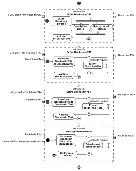
Figure 1.
The overview of the MDA-based method for the smart contract development process.
The proposed method utilises UML as a basis for the definition of all proposed models (CIM, PIM, and PSM). In some respects, the UML is used as is, particularly during the specification of the smart contract behaviour. However, the structure specification is supported by additional UML metamodel extensions, which include blockchain-specific stereotypes and datatypes. In each upcoming section, the metamodels of each model of the MDAsmartCD method are presented, encompassing the elements of UML metamodel and their extensions. For each model, the model definition steps and model transformation algorithms are also presented.
The MDAsmartCD method (Figure 1) starts with the Blockchain CIM definition which is supported by the provided UML profile for Blockchain CIM. In Blockchain CIM, a developer outlines business processes and uses the defined information for the specification of the use case and domain class model. Once the specification is completed, the model is validated using the Object Constraint Language (OCL) validation rules. The validation rules check model conformance to the Blockchain CIM requirements (usage of stereotypes and elements, model structure and composition). The final Blockchain CIM is used as an input for the definition of Blockchain PIM.
The Blockchain PIM definition starts with a model-to-model (M2M) transformation of Blockchain CIM to Blockchain PIM. The transformation creates Blockchain PIM elements based on Blockchain CIM elements and applies specific Blockchain PIM stereotypes according to the outlined ATL rules. The Blockchain PIM then can be extended by the developer via augmentation of the model (e.g., developer can specify additional state machine behaviours and smart contract structural features based on business processes). The Blockchain PIM is also validated using the defined OCL rules in the Blockchain PIM profile: if the model is correctly defined (a class for smart contract exists, smart contract has defined operations, opaque behaviors, state machines); if Blockchain CIM stereotypes are correctly applied; if state machines are correctly specified (e.g., transition triggers correspond to smart contract operations). The validated Blockchain PIM is further used as an input for the definition of Blockchain PSM.
The Blockchain PSM definition begins with the M2M transformation implemented using ATL rules. For a selected platform, the M2M algorithm transforms Blockchain PIM elements to Blockchain PSM elements, applies Blockchain PSM stereotypes, and, based on the specified state machine behaviours, creates new platform-specific structural features. The developer once again can augment the model, this time by utilising the provided opaque behavior library elements or outlining the behaviour using sequence diagrams. Lastly, the produced model is validated using OCL rules by checking the conformance to the specifics of the selected blockchain platform, especially the correct stereotype usage, model conformance to expected structure, and appropriate specifications of behavioural elements.
In the final step of the MDAsmartCD method, the development of the smart contract starts with the model to text (M2T) transformation, during which the validated Blockchain PSM is used as an input. In this transformation, MOFM2T templates are used to define the mappings of Blockchain PSM metamodel elements to implementation language concepts in order to generate platform-specific smart contract code. Once generated, the smart contract code can be extended manually or used as is for the deployment to a blockchain technology platform.
3.1. Blockchain CIM Definition
The purpose of Blockchain CIM is to define how blockchain technology could be integrated into the reorganisation and decentralisation of specific business processes as well as the context of these processes. The metamodel of Blockchain CIM is presented in Figure 2, which includes not only the UML metamodel elements of activity, use case, and class diagrams, but also the extending blockchain-specific stereotypes for class and actor metaclasses.
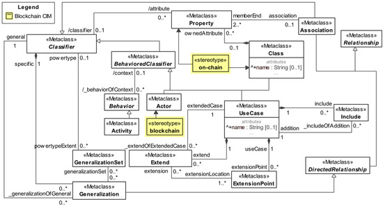
Figure 2.
Blockchain CIM. Extended UML metamodel.
As proposed in MDA, at the CIM definition step, the developer outlines the business process model (represented using UML activity diagrams). Based on the definition of business processes, the developer outlines requirements in the form of a use case model. The use case model includes functional requirements, some of which are associated with the actor with the «blockchain» stereotype, which denotes the use case integration with the blockchain (Figure 2). Additionally, a domain class model can be outlined and the classes and properties in the domain model can be specified using the «on-chain» stereotype. This stereotype denotes the domain elements (classes, properties, association ends) that should be further relocated to the blockchain.
In the definition of Blockchain CIM, the development of a business process model is an initial step which serves as a basis for the specification of use case and domain class models. The transition from business processes to use cases and domain classes is performed manually at the same CIM abstraction level since the information about business processes cannot be automatically translated into use case and domain models, since such a process requires some design decisions to be made by the developer. Thus, UML activity diagrams are outlined as an intermediate step, and only elements from the use case and class diagrams are utilised in the automated transformation from Blockchain CIM to Blockchain PIM.
3.2. Transformation from Blockchain CIM to Blockchain PIM
Blockchain PIM represents the design model of the smart contract, specified without the specific details of the blockchain implementation platform. Blockchain PIM (Figure 3) encompasses UML class diagrams for smart contract structure specification and can also include UML state diagrams for behaviour specification. The Blockchain PIM profile contains not only standard UML metamodel elements, but also the «SmartContract» stereotype, an additional address type, and the «pay» stereotype, which denotes properties and operations concerning the cryptocurrency transactions. The profile also includes validation rules that validate the model’s conformance to the defined PIM structure for ensuring the correct input to subsequent transformations.
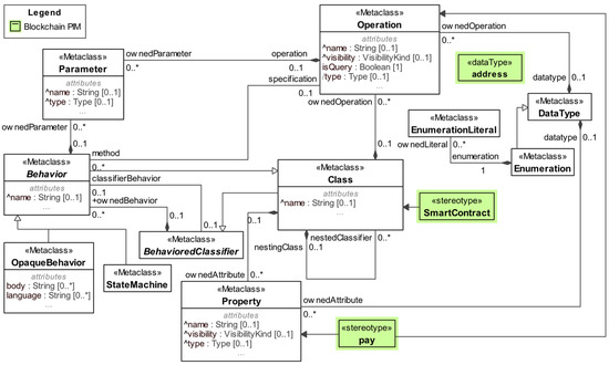
Figure 3.
Blockchain PIM. Extended UML metamodel.
The transition from Blockchain CIM to Blockchain PIM is performed by employing a model-to-model (M2M) transformation that maps input model elements to the output model elements, according to specified transformation templates. During this transformation (Figure 4), a smart contract structure is generated based on the CIM use case model. First, the PIM «SmartContract» class is created, and the CIM use cases that were associated with the «blockchain» actor are transformed to the PIM «SmartContract» class operations.
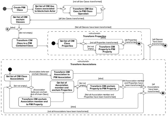
Figure 4.
Blockchain CIM to Blockchain PIM transformation.
Additionally, if the CIM domain class model is defined and includes the domain classes with the «on-chain» stereotype, these classes are directly transformed into the PIM «SmartContract» contained classes representing data structures. Furthermore, the rest of the domain class model is analysed, and if it is found that «on-chain» properties (or association ends which are also properties) exist not in an «on-chain» class, such CIM properties are transformed to the properties of the PIM contained class representing data structure. If in CIM, associations exist between «on-chain» classes, they are transformed to PIM associations between the PIM «SmartContract» contained classes representing data structures.
Once the automated part of the transformation is complete, the developer can manually extend the PIM according to the logic specified in the CIM business processes. In terms of behaviour specification, the developer can define the smart contract state machines. The approach enables the specification of a smart contract behaviour as a classifier behaviour, while also supporting state machines mapped to a data structure, specified as an ownedBehavior. The state machine itself may include the states, transitions, and transition triggers specified as either call events or time events, and have additional behavioural logic included and specified as transition effects. Furthermore, the state machine outlines the transitional behaviour between states, which locks specific operation usage depending on the state the smart contract or data structure is in. The transitional logic may also include conditions specified either as transition guards or using junction, choice pseudostates.
The resulting Blockchain PIM contains the smart contract structure specification in the UML class diagram and can also incorporate the behaviour specification in the UML state diagram. This design model can be further transformed into Blockchain PSM for the platform of choice.
3.3. Transformation from Blockchain PIM to Blockchain PSM
Our approach currently has two defined PSMs: Ethereum PSM and Hyperledger Fabric PSM. We chose to demonstrate the multiplatform aspect of our approach by outlining these two PSMs, but the set of PSMs can be further extended by defining the UML profile for other platforms if such a need arises. Blockchain PSMs in MDAsmartCD have their own UML profiles, encompassing platform-specific stereotypes, data types, and validation rules that check model conformance to the required PSM structure. The stereotypes and datatypes of both the Ethereum and Hyperledger PSMs are presented in Figure 5, which also defines their relation to the standard UML metamodel. The profiles also include platform-specific—Ethereum PSM and Hyperledger Fabric PSM—OpaqueBehavior library elements which can be used as code embeddings and are based on the platform documentation examples and ERC standard implementations outlined in [38,39].

Figure 5.
The extended UML metamodel with stereotypes and datatypes for both Hyperledger Fabric Blockchain PSM and Ethereum PSM.
The M2M transformation algorithms to generate Ethereum PSM or Hyperledger Fabric PSM (Figure 6 and Figure 7, respectively) are similar, as they both use the same Blockchain PIM as an input. At the start, a PSM «contract» (in Ethereum PSM) or «chaincode» (in Hyperledger Fabric PSM) class is created that is appended with model elements that were previously outlined in the Blockchain PIM model. The main difference between the two platforms in this step is the stereotypes applied, and the data types of these elements. In both cases, the stereotype applied to an element denotes the specific structural concept implementation in a particular technology.
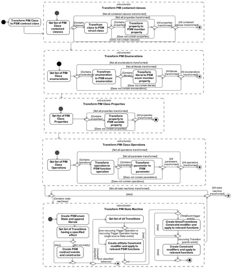
Figure 6.
Blockchain PIM to Ethereum PSM transformation.
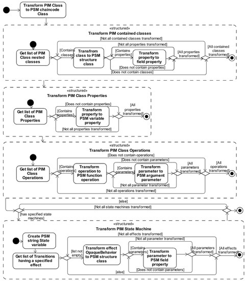
Figure 7.
Blockchain PIM to Hyperledger Fabric PSM transformation.
After the transformation to either of the two Blockchain PSM variants, the specified models can be extended by additional logic. Such an extension can be executed by specifying interactions (in the form of UML sequence diagrams) or opaqueBehaviors for specific functions, or by incorporating the opaqueBehaviors from the provided curated library of code embeddings based on the platform documentation or community-based ERC application-level standards.
The final version of Blockchain PSM encompasses UML class diagrams for smart contract structure and can also encompass a combination of several types of behaviour specifications: UML state machine diagrams, UML sequence diagrams, and embedded code as opaqueBehaviors. The resulting Blockchain PSM is validated for conformance to the PSM structure and can then be transformed into smart contract code for the selected platform.
3.4. Transformation from Blockchain PSM to Smart Contract Code
The Ethereum PSM or Hyperledger Platform PSM is further transformed into a smart contract in Solidity or Go programming language, respectively. Model-to-text transformations (M2T) are employed in this process and the produced smart contract code can be used for deployment on a specific platform as is or can be manually extended by the developer if needed. Metamodels for both implementation languages were developed (the Solidity metamodel in Figure 8 and the Go metamodel in Figure 9) and were used to define transformations from PSM elements to Solidity or Go language concepts.
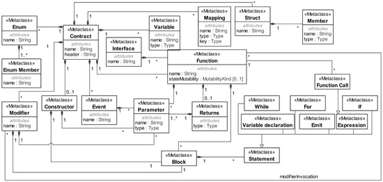
Figure 8.
Ethereum Solidity smart contract metamodel.
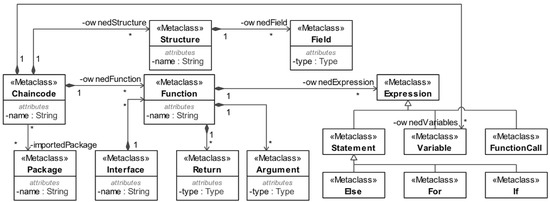
Figure 9.
Hyperledger Fabric Go chaincode metamodel.
During the Blockchain PSM transformation to smart contract code, a specific platform smart contract code file (Solidity file for Ethereum PSM, or a Go file for Hyperledger Fabric PSM) is created. The file is then appended line by line based on the specified Blockchain PSM structure and behaviour as the PSM stereotypes are directly related to the Ethereum Solidity smart contract (Figure 8) and Hyperledger Fabric Go chaincode (Figure 9) metamodels.
In both cases, for the transformation to the Solidity smart contract (Figure 10) or the Go chaincode (Figure 11) source code, the file is appended with the Solidity or Go Variables (Figure 8 and Figure 9) based on the Blockchain PSM «variable» properties. Additionally, depending on the PSM property stereotype, in the case of the Ethereum PSM, a Solidity mapping may also be appended to the code. Based on «struct» from Ethereum PSM and «structure» from the Hyperledger Fabric PSM classes, the data structs or structures are appended to Solidity or Go code, respectively, together with their Member or Field Elements based on PSM «member» or «field» properties. Next, in the case of the Ethereum PSM, the enumerations are transformed into Solidity «enums» and have their literals appended as «enum» members. Afterwards, the Solidity file is appended with the modifiers, based on the PSM «modifier» constraints. The enumeration and constraint transformation steps are not present in the case of the Hyperledger Fabric PSM, as the Go chaincode does not support such concepts (Figure 9).
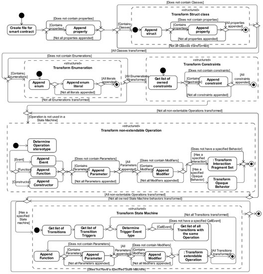
Figure 10.
Ethereum PSM to Solidity smart contract code transformation.
Afterwards, for both the Ethereum PSM and Hyperledger Fabric PSM, the PSM operations transformation starts during which functions based on «function» operations that are not utilised in the state machines are appended to the smart contract or chaincode. Additionally, in the case of Ethereum PSM, if any operations exist with an applied «constructor» or «event» stereotype, instead of Solidity function, a constructor or an event is created instead. As the concepts of constructor and event are not supported in Go, this step is skipped in the Hyperledger PSM transformation. Additionally, in any Blockchain PSM, provided that the specific «function» operations have a behaviour specified in a form of interaction or the opaqueBehavior, this behaviour is also included as a function body (blocks or expressions). Otherwise, if the behaviour was not specified, such a step is skipped, which results only in a function header that includes the function name, parameters or arguments, platform-specific data types, and modifier invocations (in Solidity).

Figure 11.
Hyperledger Fabric PSM to Go chaincode code transformation.
Figure 11.
Hyperledger Fabric PSM to Go chaincode code transformation.

Next, state machines are analysed, and any functions based on the PSM «function» operations that are used in state machines as transition call events are appended to the smart contract or chaincode. The appended function header includes the function name, parameters, data types, and (only in Solidity) modifier invocations. Afterwards, based on PSM state machine, the function body code is extended with conditional statements or expressions which ensure that functions are only called when a contract is in a specific state. It is worth mentioning that during the transformation, the conditional statements or expressions are appended at the start of the function body, and the state variable declarations are included before the specific function return statement.
The result of this final transformation is the executable code of the smart contract in Solidity (as sol file) or chaincode in Go (as Go file), which can be deployed on a selected platform.
4. Application of the MDAsmartCD Method for Development of Hackathon Certificate Issuing Solution
For the purposes of method validation, MDAsmartCD was applied in the development of a smart contract-based solution for hackathon certificate issuing, named HackChain. Following the development guidelines, the Blockchain CIM, Blockchain PIM, and Ethereum and Hyperledger Fabric PSMs were defined for the HackChain. The resulting diagrams for each model are presented in this section, and the generated smart contract code in Solidity and chaincode in Go is available at https://github.com/m-jurgelaitis/MDAsmartCD (accessed on 26 December 2022).
All models were developed using the MagicDraw UML modelling tool and exported in XMI file format as input for further model transformations. The Eclipse ATL tool was used for transformations between models (M2M), which processed the input provided using the implemented transformation templates and produced another XMI file as output. The generated XMI file was then successfully imported back to MagicDraw and extended according to the Blockchain PIM (and later Blockchain PSM) extension step rules. For the last transformation from PSM models to code (M2T), the Eclipse Acceleo tool was used, which also processed the input XMI file using the implemented transformation templates and produced smart contract code in Solidity and Go languages. The generated code was deployed on Ethereum and Hyperledger Fabric blockchains: the generated HackChain.sol file was deployed on the Goerli test network and the generated HackChain.go file was deployed on a private Hyperledger Fabric network consisting of two peers.
4.1. Blockchain CIM for HackChain
As the proposed MDAsmartCD method includes the definition of business processes in the first step of Blockchain CIM development, the activity diagrams for business processes were outlined as a basis for the subsequent model specification.
Specifically, two relevant business processes have been identified, one that deals with the certificate issuing (Figure 12), and the other with the evaluation of submitted participant solutions (Figure 13). The certificate issuing process starts with the participant requesting a certificate from an organiser, which can occur at any point in time, after or even during the hackathon. The organiser, depending on the hackathon timeline, may choose to issue a certificate for joining the event, or, if the hackathon results have been announced, to issue a certificate for participation or solution. The issuing process when the hackathon results have been announced depends on the participants’ involvement in the event and the evaluation of the submitted solution. The evaluation is performed after the hackathon event has ended, and the solutions are collected and assessed by the judges. Later, the assessments for each solution and all judges are collected, and the final evaluation by the organisers is made. During the solution evaluation, it is determined whether the submitted participant solution meets the outlined hackathon criteria, and the hackathon results are announced. In practice, the evaluation results are shared with the participants and include feedback from the judges and organisers.
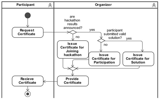
Figure 12.
Blockchain CIM certificate issuing business process: activity diagram.
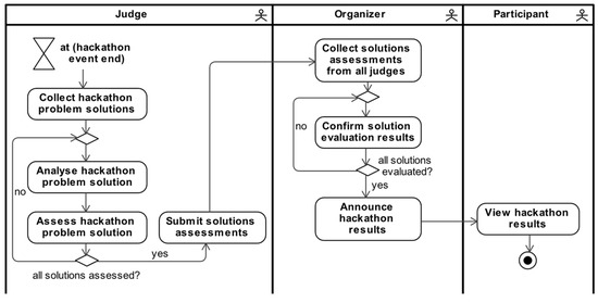
Figure 13.
Blockchain CIM evaluate solutions business process: activity diagram.
In the next step, a use case model was specified that contained two use cases (covering the functionality of certificate creation and evaluation results confirmation) based on previously defined business processes. As can be seen in Figure 14, both use cases were associated with the «blockchain» actor, thus denoting that the use cases are to be decentralised using blockchain.
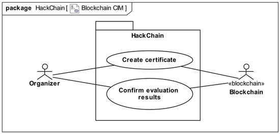
Figure 14.
Blockchain CIM HackChain use case model: use case diagram.
Furthermore, a domain model was specified that contains relevant domain classes (Figure 15). The Certificate class had the «on-chain» stereotype applied, again depicting that the Certificate and its data should be relocated to the blockchain. Several other class properties (Participants’ name and surname, Solutions’ validity, Hackathons’ title) and association ends (participant, hackathon, solution) were specified as having an «on-chain» stereotype. This design decision depicts additional Certificate properties to be relocated to the blockchain.
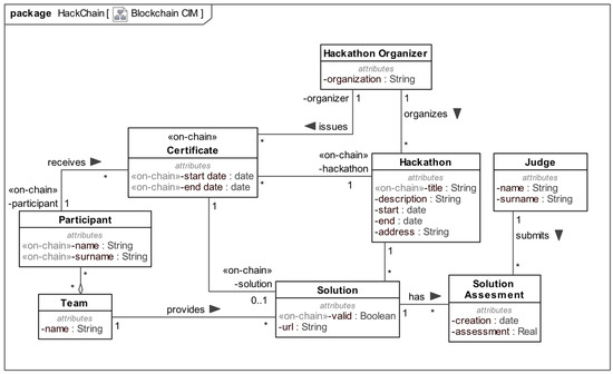
Figure 15.
Blockchain CIM HackChain domain model: class diagram.
4.2. Blockchain PIM for HackChain
The M2M Blockchain CIM to Blockchain PIM transformation result is outlined in Figure 16. During the transformation, a created SmartContract class was appended with two operations (createCertificate and confirmEvaluationResults) based on the CIM use cases Create Certificate and Confirm Evaluation Results that were associated with the «blockchain» actor. Furthermore, the specified Blockchain CIM domain model classes were analysed, based on which the SmartContract class was appended with a contained Certificate class, representing the data structure. The Certificate class also includes all properties from Blockchain CIM that had the «on-chain» stereotype applied. Additionally, the Certificate class also includes the properties based on the Blockchain CIM «on-chain» association ends; these properties are outlined as references to the Blockchain CIM Hackathon, Participant, and Solution classes’ unique identifiers, and are of Integer type.
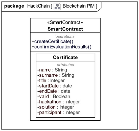
Figure 16.
Blockchain CIM to Blockchain PIM transformation result: class diagram.
After the transformation was complete, as supported by the method, the SmartContract class was manually updated. Specifically, the operations had their parameters specified, because this specification step requires additional input from the developer and cannot be fully automated. Furthermore, two class properties tokenCounter and certificates were created, as well as the Certificate class properties owner and tokenID, to better keep track of unique certificate records and the certificate token ownership. Additionally, changes to improve readability were made to the naming of elements of the «SmartContract» class: the SmartContract class was renamed to HackChain; the Certificate properties title and valid were renamed to hackathon and solutionValid, since before the transformation, these properties belonged to Solution and Hackathon classes, respectively. The resulting extended Blockchain PIM class diagram is presented in Figure 17. Furthermore, a behaviour was outlined for the Certificate class using the state machine diagram (Figure 18). The behaviour specification is based on the Issue certificate and Evaluate submitted solutions business processes specified in the Blockchain CIM. As outlined in the state machine (Figure 18), the Certificate is created in an Issued state, denoting that the Certificate was issued to a participant, and can later transition to the Issued for participation state or Issued for a solution state. As the naming implies, the Issued for participation Certificate is awarded to a participant for joining the hackathon but not having a solution submitted during the hackathon or having submitted an invalid solution, and the Issued for a solution Certificate is awarded to a participant who submitted a valid solution.
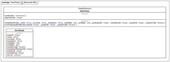
Figure 17.
The extended HackChain Blockchain PIM: class diagram.
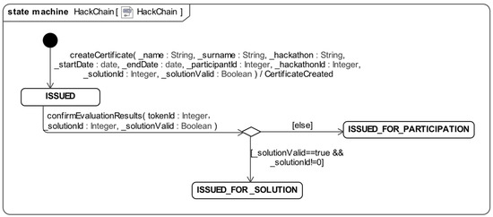
Figure 18.
The extended HackChain Blockchain PIM: state machine diagram.
4.3. Ethereum PSM for HackChain
During the transformation from HackChain Blockchain PIM to Ethereum PSM, the PIM smart contract structural elements were mapped to Solidity concepts and specific UML stereotypes were applied to model elements. Based on the «SmartContract» HackChain class in the Blockchain PIM, a «contract» HackChain class was produced in the Ethereum PSM (Figure 19), and the transformed structural class elements had Ethereum PSM profile stereotypes applied. Furthermore, based on the PIM containing class Certificate, a «struct» Certificate class was created in PSM, and an additional «enum» CertificateState enumeration and a state «variable» property were created in the Certificate «struct» class. The «enum» CertificateState lists all the states from the PIM state machine as enumeration literals. Each outlined operation had a «function» stereotype applied and based on the state machine diagram, an additional «event» CertificateCreated operation was also appended (based on the PIM transition trigger effect CertificateCreated). The state machine was also transformed from PIM to Ethereum PSM (Figure 20). The behaviour of the state machine between the Ethereum PSM (Figure 20) and the Blockchain PIM (Figure 18) differs slightly; the only difference is that the operation call events refer to the transformed «contract» class «function» operations createCertificate and confirmEvaluationResults.
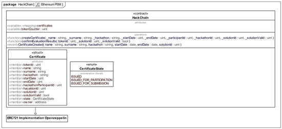
Figure 19.
HackChain Ethereum PSM: class diagram.
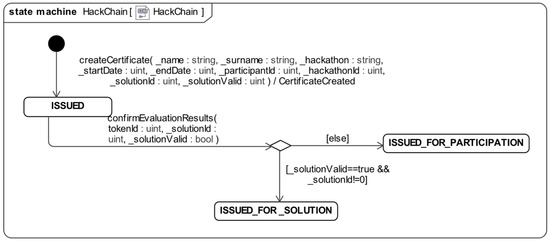
Figure 20.
HackChain Ethereum PSM: state machine diagram.
After the transformation, the transformed Ethereum PSM was extended by specifying the smart contract inheritance from the ERC 721 standard implementation based on the included Ethereum PSM OpaqueBehavior library. Such an extension is specified as a generalisation between the classes, and thus the «function» behaviour implementations provided by the standard are inherited as well.
4.4. Hyperledger Fabric PSM for HackChain
The Hyperledger Fabric PSM is composed of a chaincode structure specification (Figure 21) and the behaviour specification outlined using the state machine diagram (Figure 22). During the transformation to Hyperledger Fabric PSM, a HackChain «chaincode» class was created based on the HackChain PIM «SmartContract» class. The transformed «chaincode» class includes two «structure» classes: Certificate, based on the PIM contained class Certificate; and CertificateCreated, based on the PIM state machine transition trigger effect CertificateCreated. The «chaincode» class also contains previously outlined operations from PIM and every transformed operation has a «function» stereotype applied and additional parameters ctx TransactionContextInterface and err error, as these parameters are required for all functions querying the blockchain. The name of each class feature is based on its visibility in Blockchain PIM (PIM public visibility features are named starting with a capital letter in Hyperledger Fabric PSM). Additionally, the Hyperledger Fabric PSM state machine was transformed from PIM having the transition trigger call event operations referencing the «chaincode» class «function» CreateCertificate and ConfirmEvaluationResults operations. Furthermore, the state «field» property (of the string type) of the Certificate «structure» class is used to denote the state machine states, since the enumerations are not supported in Go.
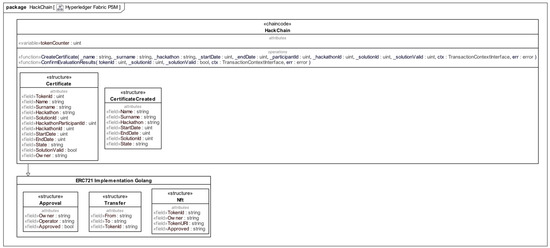
Figure 21.
HackChain Hyperledger Fabric PSM: class diagram.
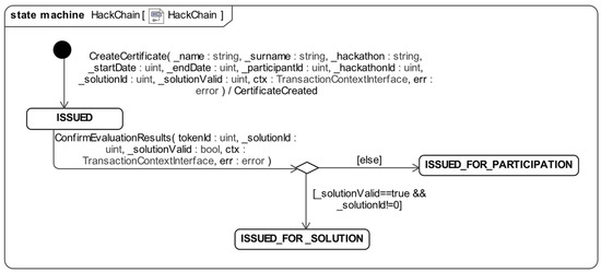
Figure 22.
HackChain Hyperledger Fabric PSM: state machine diagram.
Like in the Ethereum PSM case, the Hyperledger Fabric PSM was extended manually: the HackChain «chaincode» class was specified to inherit the functionality of the ERC 721 standard implementation, and the opaqueBehavior implementations were selected from the Hyperledger Fabric PSM OpaqueBehavior library.
4.5. The Metrics of the Developed HackChain Models and the Generated Code
The model-to-model transformation results are presented in Table 2, where the quantitative model metrics and the differences between the Blockchain CIM, the transformed Blockchain PIM, and the extended Blockchain PIM are outlined. For each model, the UML model element counts that were directly utilised during the transformation or are a result of the transformation are presented.
Table 2.
HackChain Blockchain CIM to Blockchains PIM transformation metrics.
Based on the two use cases in the Blockchain CIM use case model, the generated Blockchain PIM for HackChain has a single «SmartContract» class with two operations. Furthermore, there is a single contained class in Blockchain PIM that encompasses in total nine properties based on six «on-chain» properties and three «on-chain» association member end properties defined in the Blockchain CIM domain class model. After the transformation to the Blockchain PIM, this model was manually extended with additional 16 model elements, the majority of which (12) were operation parameters. When considering the main structural model elements (classes, properties, and operations), 14 out of 18 Blockchain PIM elements were automatically transformed from Blockchain CIM; thus, PIM was extended with four additional elements, all of them being properties. In contrast to structure specification, the behaviour in PIM was specified manually; therefore, the state machine elements are present only in extended Blockchain PIM. The operations of the «SmartContract» class were used in the specification of the smart contract behaviour, represented using the state machine diagram, the logic of which was based on the Blockchain CIM business processes.
The resulting Blockchain PIM was used during the transformations to the Ethereum PSM and Hyperledger Fabric PSM and the quantitative metrics of both PSMs are presented in Table 3. The differences between the metrics of the two Blockchain PSMs are directly related to the supported Solidity and Go metamodel concepts.
Table 3.
HackChain Blockchain PSM metrics.
The produced Blockchain PSMs differ in terms of the smart contract structure: due to the platform specifics, the Ethereum PSM has an additional mapping property, while the Hyperledger Fabric does not need it; based on the PIM state machine transition effect, the Ethereum PSM has an additional «event» operation, while the Hyperledger Fabric PSM has a CertificateCreated «structure» class; for denoting the certificate state, the Ethereum PSM has state «member» property and «enum» CertificateState with literals, while Hyperledger Fabric PSM has a state «field» string property. Additionally, for implementing the NFT standard functionality (minting of tokens), both Blockchain PSMs were specified to inherit the ERC 721 standard implementations from the OpaqueBehavior library: Ethereum PSM «contract» HackChain inherits in total 36 elements and the Hyperledger Fabric «chaincode» HackChain inherits 26 additional elements.
The defined Ethereum PSM and Hyperledger Fabric PSM were used to generate the HackChain Solidity smart contract and Go chaincode, respectively. To evaluate whether the generated smart contracts meet the requirements defined in Blockchain CIM, both the Go chaincode and the Solidity smart contract were tested using the same test scenarios (test cases are provided in the https://github.com/m-jurgelaitis/MDAsmartCD accessed on 26 December 2022). Furthermore, the generated smart contracts were unit tested using the supplied smart contract unit tests to the ERC721 standard.
Furthermore, both generated smart contracts were analysed for vulnerabilities. The generated Go chaincode was evaluated using HFCCT [41], a framework for the detection of Hyperledger Fabric smart contracts. The framework enables the detection of 17 types of common vulnerabilities, and no issues were detected during the HackChain Go chaincode evaluation. The generated Solidity HackChain smart contract was evaluated with the Slither [42] static code analysis tool, which is used for automated vulnerability detection, optimisation detection, code understanding analysis, and assisted code review. Slither checks 80 vulnerabilities, and no high, medium, or low issues were found in the generated Solidity smart contract.
The HackChain smart contract Solidity and Go chaincode metrics were calculated using the Lizard [43] code complexity analysing tool and are presented in Table 4. The presented analysis results encompass metrics such as the NLOC (normalised lines of code), CCN (cyclomatic complexity number), token (token count which refers a number of code blocks, expressions, annotations, methods, and object access), and parameters (parameter count of functions). For both smart contract and chaincode, the code metrics do not include the inherited elements from the ERC 721 standard. The HackChain Go chaincode functions have a higher cyclomatic complexity number compared to the HackChain Solidity smart contract functions (Figure 23). A higher CCN means more complex code, which is more difficult to read and understand. In HackChain.go, a higher complexity can be attributed to language specifics, as in Go, for querying the ledger data, additional calls to ctx TransactionContextInterface are required, which also come with additional error handling wrappers.
Table 4.
Smart contract code metrics for Ethereum and Hyperledger Fabric platforms.
Table 4.
Smart contract code metrics for Ethereum and Hyperledger Fabric platforms.
| HackChain Solidity Smart Contract | ||||
| Executed Function | NLOC | CCN | Token | Parameters |
| createCertificate | 7 | 1 | 109 | 9 |
| confirmEvaluationResults | 10 | 4 | 74 | 3 |
| HackChain Go Chaincode | ||||
| Executed Function | NLOC | CCN | Token | Parameters |
| CreateCertificate | 16 | 3 | 154 | 10 |
| ConfirmEvaluationResults | 24 | 7 | 142 | 4 |

Figure 23.
HackChain.sol and HackChain.go code complexity comparison.
Figure 23.
HackChain.sol and HackChain.go code complexity comparison.

For evaluation purposes, the Solidity smart contract was hosted on the Goerli test network. The Go chaincode was deployed on a local Hyperledger Fabric network consisting of two peers. For hosting this network, a server having an Intel Xeon Silver 4114 CPU featuring 16 GB of RAM with data stored on the SSD storage was used. The server was running on an Ubuntu 18.04 operating system and using Docker containers as a Peer environment for Hyperledger Fabric 2.2 with CouchDB 2.3.1 as the state database.
The deployed smart contracts were experimented upon by imitating the certificate issuing processes. For both the Ethereum and Hyperledger Fabric smart contracts, the same data set was used to execute smart contract functions in the same workflow and record the execution metrics. In both cases, 18 certificates were created (state machine state ISSUED) for hackathon participants. To cover all transitions specified in the state machine, three different situations were included in the workflow of the experiment:
- Nine participant certificates were confirmed to have submitted valid solutions, the solution references were updated, and the certificates were updated to the ISSUED_FOR_SOLUTION state.
- Six hackathon participant certificates were updated to the ISSUED_FOR_PARTICIPATION state, as they were determined to have submitted an invalid solution (the reference to a solution was also updated).
- The remaining three participant certificates were updated to the ISSUED_FOR_PARTICIPATION state, as participants have not submitted a solution.
Additionally, the Solidity of the smart contract execution costs were recorded once the smart contract was hosted on a Goerli testing network. The transaction fees were recorded (Table 5), which represent the total amount of ETH (Ethereum cryptocurrency) paid to the block producers for processing all transactions, the total amount of GAS usage per all transactions, and the average function GAS usage cost. When compared, the createCertificate function execution costs are higher, as during the execution, a new Certificate data record is created and an NFT token is minted, as opposed to the confirmEvaluationResults when only the specific Certificate data record values are updated.
Table 5.
Smart contract execution metrics for Ethereum and Hyperledger Fabric platforms.
Similarly, the generated HackChain chaincode was hosted on a Hyperledger Fabric network. For each Hyperledger Fabric chaincode function evaluated, a total execution time for all transactions was calculated (Table 5), which includes the duration of state validation, committing data to CouchDB storage and committing data to the blockchain. The difference between functions is marginal because both functions require multiple calls to the TransactionContextInterface, to which most of the execution time is attributed.
Although the code execution metrics are too different to be compared directly, both HackChain.sol and HackChain.go were successfully compiled, deployed, and executed using the outlined workflow. In the Hyperledger Fabric, a total of 38 blocks (39 transactions) were created during the experiment, while in the Ethereum Goerli test network, a total of 37 blocks (37 transactions) were produced. The difference between the number of blocks can be attributed to the mechanism that the networks use to deploy smart contracts. In conclusion, during the execution of the workflow, both implementations demonstrated analogous behaviour and recorded the same data in their respective blockchain data storages.
5. Discussion and Conclusions
The paper presents an MDA-based method for smart contract development (MDAsmartCD) which, when compared to other MDA-based methods, covers the complete set of MDA proposed models, uses Unified Modeling Language (UML) through all the models; utilises not only smart contract structure definition but also behaviour specification using a state machine, interaction specification, and opaqueBehavior code embeddings; and produces smart contract code for two implementation platforms. The model-driven development principles prominent in the proposed method support requirement specification, design, and code production activities, thus placing a heavier focus on earlier development phases than straight-up implementation.
In MDAsmartCD, the Blockchain CIM, PIM, and PSM definitions are based on the UML, and transitions between different abstraction levels are automated by model-to-model transformations. The transformation from Blockchain PIM to Blockchain PSM is fully automated and capable of producing a model that not only directly maps the Blockchain PIM defined elements with implementation platform concepts, but also appends additional elements based on the specified behaviour or the implementation platform specifics. In order to produce a more comprehensive smart contract, the definition of models requires manual extensions by the developer, as is the case of Blockchain PIM definition, but moving forward, the transformations from the Blockchain PIM to two different Blockchain PSMs, and ultimately to two different implementation languages, are capable of producing smart contract code with little to no developer intervention. Code generation using model-to-text transformation is fully automated and can be used to generate compilable and executable code ready for deployment on Ethereum and Hyperledger Fabric blockchains. As demonstrated by the experiment, when following the same workflow scenario, the deployed smart contracts behave identically and record analogous results in blockchain data storage.
While the presented model-driven development approach can automate the design and implementation of smart contracts, the method and its evaluation have several limitations. The application of the method was demonstrated by creating HackChain, a hackathon certificate issuing solution; still, the method implementation could additionally undergo a usability study as the method requires additional efforts in terms of model specification. The evaluation of generated code is also limited, as a single static code analysis tool cannot be used for analysis of both smart contracts. Although the Slither tool performs an extensive analysis, it only supports the Solidity programming language. For that reason, an additional static code analysis was performed for Go chaincode using the HFCCT tool, which is capable of analysing Go chaincode but detects only a limited set of common types of vulnerabilities and issues.
Although the process of modelling is not as straightforward as implementation, it allows the development of a generic model that can be used to generate multiple platform-specific models. Furthermore, smart contract model specification at different abstraction layers also encourages the developer to validate the smart contract design at several key points in the development process, thus facilitating the development of more robust smart contracts. Modelling also encourages the reusability of models not only when the blockchain technology is updated but allows development to pivot to an entirely different platform if it is supported by the method. The multiplatform aspect was demonstrated using two different platforms, but the set of platforms can be extended further following the guidelines provided by the method.
Currently, the scope of the MDAsmartCD method deals with the smart contract code production starting from requirement specification, design, and proceeding to the implementation, but it can be extended to cover even more development phases. In the future, we plan not only to extend the set of supported implementation platforms of the method, but also to cover automation of other development phases such as testing and deployment.
Author Contributions
Conceptualization, M.J. and L.Č.; Methodology, M.J. and L.Č.; Software, M.J., K.B. and V.D.; Validation, M.J., L.Č. and R.B.; Writing—original draft, M.J.; Writing—review & editing, M.J., L.Č., K.B., R.B. and V.D.; Visualization, M.J.; Supervision, R.B. All authors have read and agreed to the published version of the manuscript.
Funding
This research received no external funding.
Institutional Review Board Statement
Not applicable.
Informed Consent Statement
Not applicable.
Data Availability Statement
No new data were created or analysed in this study. Data sharing is not applicable to this article.
Conflicts of Interest
The authors declare no conflict of interest.
References
- Monrat, A.A.; Schelén, O.; Andersson, K. A Survey of Blockchain From the Perspectives of Applications, Challenges, and Opportunities. IEEE Access 2019, 7, 117134–117151. [Google Scholar] [CrossRef]
- Metcalfe, W. Ethereum, Smart Contracts, DApps. In Blockchain and Crypto Currency; Yano, M., Dai, C., Masuda, K., Kishimoto, Y., Eds.; Springer: Singapore, 2020; pp. 77–93. ISBN 978-981-15-3376-1. [Google Scholar]
- Zou, W.; Lo, D.; Kochhar, P.S.; Le, X.B.D.; Xia, X.; Feng, Y.; Chen, Z.; Xu, B. Smart Contract Development: Challenges and Opportunities. IEEE Trans. Softw. Eng. 2019, 47, 2084–2106. [Google Scholar] [CrossRef]
- Berdik, D.; Otoum, S.; Schmidt, N.; Porter, D.; Jararweh, Y. A Survey on Blockchain for Information Systems Management and Security. Inf. Process. Manag. 2021, 58, 102397. [Google Scholar] [CrossRef]
- Sánchez-Gómez, N.; Torres-Valderrama, J.; García-García, J.A.; Gutiérrez, J.J.; Escalona, M.J. Model-Based Software Design and Testing in Blockchain Smart Contracts: A Systematic Literature Review. IEEE Access 2020, 8, 164556–164569. [Google Scholar] [CrossRef]
- Fahmideh, M.; Grundy, J.; Ahmad, A.; Shen, J.; Yan, J.; Mougouei, D.; Wang, P.; Ghose, A.; Gunawardana, A.; Aickelin, U.; et al. Engineering Blockchain-based Software Systems: Foundations, Survey, and Future Directions. ACM Comput. Surv. 2022, 55, 1–44. [Google Scholar] [CrossRef]
- Miraz, M.H.; Ali, M. Blockchain Enabled Smart Contract Based Applications: Deficiencies with the Software Development Life Cycle Models. Baltica 2020, 33, 101–116. [Google Scholar]
- Zheng, Z.; Xie, S.; Dai, H.N.; Chen, W.; Chen, X.; Weng, J.; Imran, M. An overview on smart contracts: Challenges, advances and platforms. Future Gener. Comput. Syst. 2020, 105, 475–491. [Google Scholar] [CrossRef]
- Vacca, A.; Sorbo, A.D.; Visaggio, C.A.; Canfora, G. A systematic literature review of blockchain and smart contract development: Techniques, tools, and open challenges. J. Syst. Softw. 2021, 174, 110891. [Google Scholar] [CrossRef]
- Sebastián, G.; Gallud, J.A.; Tesoriero, R. Code generation using model driven architecture: A systematic mapping study. J. Comput. Lang. 2020, 56, 100935. [Google Scholar] [CrossRef]
- Levasseur, O.; Iqbal, M.; Matulevičius, R. Survey of Model-Driven Engineering Techniques for Blockchain-Based Applications. In Proceedings of the Forum at Practice of Enterprise Modeling 2021, Riga, Latvia, 24–26 November 2021. [Google Scholar]
- Hsain, Y.A.; Laaz, N.; Mbarki, N.L. Ethereum’s Smart Contracts Construction and Development using Model Driven Engineering Technologies: A Review. Proc. Comput. Sci. 2021, 184, 785–790. [Google Scholar] [CrossRef]
- Object Management Group. Model Driven Architecture (MDA) MDA Guide rev. 2.0. 2014. Available online: https://www.omg.org/cgi-bin/doc?ormsc/14-06-01 (accessed on 13 November 2022).
- Pastor, O.; Molina, J.C. Model-Driven Architecture in Practice; Springer: Berlin, Heidelberg, 2007; ISBN 978-3-540-71868-0. [Google Scholar]
- Curty, S.; Härer, F.; Fill, H.G. Blockchain Application Development Using Model-Driven Engineering and Low-Code Platforms: A Survey. In Proceedings of the International Conference on Business Process Modeling, Development and Support, International Conference on Evaluation and Modeling Methods for Systems Analysis and Development, Leuven, Belgium, 6–7 June 2022; pp. 205–220. [Google Scholar]
- Skotnica, M.; Klicpera, J.; Pergl, R. Towards Model-Driven Smart Contract Systems—Code Generation and Improving Expressivity of Smart Contract Modeling. In Proceedings of the 20th CIAO! Doctoral Consortium, and Enterprise Engineering Working Conference Forum 2020, Bolzano, Italy, 28 September–19 October 2020, 9–10 November 2020; pp. 1–15. [Google Scholar]
- Hu, K.; Zhu, J.; Ding, Y.; Bai, X.; Huang, J. Smart Contract Engineering. Electronics 2020, 9, 2042. [Google Scholar] [CrossRef]
- Boogaard, K. A Model-Driven Approach to Smart Contract Development. Master Thesis, Utrecht University, Utrecht, The Netherlands, 2018. [Google Scholar]
- Syahputra, H.; Weigand, H. The Development of Smart Contracts for Heterogeneous Blockchains. In Enterprise Interoperability VIII. Proceedings of the I-ESA Conferences; Popplewell, K., Thoben, K.D., Knothe, T., Poler, R., Eds.; Springer: Cham, Switzerland, 2019; ISBN 978-3-030-13692-2. [Google Scholar]
- Sousa, V.A.; Burnay, C. MDE4BBIS: A Framework to Incorporate Model-Driven Engineering in the Development of Blockchain-Based Information Systems. In Proceedings of the 2021 Third International Conference on Blockchain Computing and Applications (BCCA), Tartu, Estonia, 15–17 November 2021; pp. 195–200. [Google Scholar]
- Jurgelaitis, M.; Drungilas, V.; Čeponienė, L.; Vaičiukynas, E.; Butkienė, R.; Čeponis, J. Smart Contract Code Generation from Platform Specific Model for Hyperledger Go. In Proceedings of the 9th World Conference on Information Systems and Technologies (WorldCIST’21), Terceira Island, Azores, Portugal, 30 March–2 April 2021; pp. 63–73. [Google Scholar]
- Jurgelaitis, M.; Čeponienė, L.; Butkienė, R. Solidity Code Generation from UML State Machines in Model-Driven Smart Contract Development. IEEE Access 2022, 10, 33465–33481. [Google Scholar] [CrossRef]
- Górski, T.; Bednarski, J. Transformation of the UML Deployment Model into a Distributed Ledger Network Configuration. In Proceedings of the 2020 IEEE 15th International Conference of System of Systems Engineering (SoSE), Budapest, Hungary, 2–4 June 2020; pp. 255–260. [Google Scholar]
- Górski, T.; Bednarski, J. Applying Model-Driven Engineering to Distributed Ledger Deployment. IEEE Access 2020, 8, 118245–118261. [Google Scholar] [CrossRef]
- Gao, Z.; Jiang, L.; Xia, X.; Lo, D.; Grundy, J. Checking Smart Contracts with Structural Code Embedding. IEEE Trans. Softw. Eng. 2020, 47, 2874–2891. [Google Scholar] [CrossRef]
- Antal, C.; Cioara, T.; Anghel, I.; Anta, M.; Salomie, I. Distributed Ledger Technology Review and Decentralized Applications Development Guidelines. Futur. Int. 2021, 13, 62. [Google Scholar] [CrossRef]
- Pierro, G.A. Smart-Graph: Graphical Representations for Smart Contract on the Ethereum Blockchain. In Proceedings of the 2021 IEEE International Conference on Software Analysis, Evolution and Reengineering (SANER), Honolulu, HI, USA, 9–12 March 2021; pp. 708–714. [Google Scholar]
- Hamdaqa, M.; Met, L.A.P.; Qasse, I. iContractML 2.0: A domain-specific language for modeling and deploying smart contracts onto multiple blockchain platforms. Inf. Softw. Technol. 2022, 144, 106762. [Google Scholar] [CrossRef]
- Kim, H.M.; Laskowski, M. Toward an ontology-driven blockchain design for supply-chain provenance. Intell. Syst. Account. Financ. Manag. 2018, 25, 18–27. [Google Scholar] [CrossRef]
- Zupan, N.; Kasinathan, P.; Cuellar, J.; Sauer, M. Secure Smart Contract Generation Based on Petri Nets. In Blockchain Technology for Industry 4.0. Blockchain Technologies; Rosa Righi, R., Alberti, A., Singh, M., Eds.; Springer: Singapore, 2020; pp. 73–98. ISBN 978-981-15-1137-0. [Google Scholar]
- Rocha, H.; Ducasse, S. Preliminary Steps Towards Modeling Blockchain Oriented Software. In Proceedings of the 2018 IEEE/ACM 1st International Workshop on Emerging Trends in Software Engineering for Blockchain (WETSEB), Gothenburg, Sweden, 27 May–3 June 2018; pp. 52–57. [Google Scholar]
- Garamvölgyi, P.; Kocsis, I.; Gehl, B.; Klenik, A. Towards Model-Driven Engineering of Smart Contracts for Cyber-Physical Systems. In Proceedings of the 2018 48th Annual IEEE/IFIP International Conference on Dependable Systems and Networks Workshops (DSN-W), Luxembourg, Luxembourg, 25–28 June 2018; pp. 134–139. [Google Scholar]
- Mavridou, A.; Laszka, A.; Stachtiari, E.; Dubey, A. VeriSolid: Correct-by-Design Smart Contracts for Ethereum. In Proceedings of the Financial Cryptography and Data Security 23rd International Conference, FC 2019, Frigate Bay, St. Kitts and Nevis, 18–22 February 2019; pp. 446–465. [Google Scholar]
- Kasinathan, P.; Martintoni, D.; Hofmann, B.; Senni, V.; Wimmer, M. Secure Remote Maintenance via Workflow-Driven Security Framework. In Proceedings of the 2021 IEEE International Conference on Blockchain (Blockchain), Melbourne, Australia, 6–8 December 2021; pp. 29–37. [Google Scholar]
- Marchesi, L.; Marchesi, M.; Tonelli, R. ABCDE—Agile block chain DApp engineering. Blockchain Res. Appl. 2020, 1, 100002. [Google Scholar] [CrossRef]
- Huning, L.; Iyenghar, P.; Pulvermüller, E. UML-based Model-Driven Code Generation of Error Detection Mechanisms. In Proceedings of the ICSEA 2020: The Fifteenth International Conference on Software Engineering Advances, Porto, Portugal, 18–22 October 2020. [Google Scholar]
- Lu, Q.; Binh Tran, A.; Weber, I.; O’Connor, H.; Rimba, P.; Xu, X.; Staples, M.; Zhu, L.; Jeffery, R. Integrated model-driven engineering of blockchain applications for business processes and asset management. Softw. Prac. Exp. 2021, 51, 1059–1079. [Google Scholar] [CrossRef]
- ERC|Ethereum Improvement Proposals. Available online: https://eips.ethereum.org/erc (accessed on 13 November 2022).
- Hyperledger Fabric Samples. Available online: https://github.com/hyperledger/fabric-samples (accessed on 13 November 2022).
- Amaral de Sousa, V.; Burnay, C.; Snoeck, M. B-MERODE: A Model-Driven Engineering and Artifact-Centric Approach to Generate Blockchain-Based Information Systems. In Advanced Information Systems Engineering. CAiSE 2020; Dustdar, S., Yu, E., Salinesi, C., Rieu, D., Pant, V., Eds.; Springer: Cham, Switzerland, 2020; pp. 117–133. ISBN 978-3-030-49435-3. [Google Scholar]
- Li, P.; Li, S.; Ding, M.; Yu, J.; Zhang, H.; Zhou, X.; Li, J. A Vulnerability Detection Framework for Hyperledger Fabric Smart Contracts Based on Dynamic and Static Analysis. In Proceedings of the International Conference on Evaluation and Assessment in Software Engineering 2022, Gothenburg, Sweden, 13–15 June 2022. [Google Scholar]
- Feist, J.; Grieco, G.; Groce, A. Slither: A Static Analysis Framework for Smart Contracts. In Proceedings of the 2019 IEEE/ACM 2nd International Workshop on Emerging Trends in Software Engineering for Blockchain (WETSEB), Montréal, Canada, 27 May 2019. [Google Scholar]
- Yin, T. Terryyin/Lizard: A Simple Code Complexity Analyser without Caring about the C/C++ Header Files or Java Imports, Supports Most of the Popular Languages. Available online: https://github.com/terryyin/lizard (accessed on 12 December 2022).


Disclaimer/Publisher’s Note: The statements, opinions and data contained in all publications are solely those of the individual author(s) and contributor(s) and not of MDPI and/or the editor(s). MDPI and/or the editor(s) disclaim responsibility for any injury to people or property resulting from any ideas, methods, instructions or products referred to in the content. |
© 2022 by the authors. Licensee MDPI, Basel, Switzerland. This article is an open access article distributed under the terms and conditions of the Creative Commons Attribution (CC BY) license (https://creativecommons.org/licenses/by/4.0/).