Abstract
In this paper, the issue of roll channel for attitude control for small air-to-surface missiles suffering from multiple disturbances is investigated. The dynamic model of roll channel is established and the roll controller of roll channel based on the active disturbance rejection control (ADRC) is designed. Based on the extended state observer, the disturbance is observed and compensated to track the roll rate accurately. Then, simulations and verification are carried out for rudder efficiency, barycenter location deviation, steering gear stuck, wind disturbance, drift error of inertial measurement unit (IMU) and other disturbances. The control effect is also compared with proportional integral derivative (PID) control and other ADRC algorithms. The results demonstrate that the algorithm has a good ability to suppress multiple disturbances. It can meet the control performance requirements of small air-to-surface missiles.
1. Introduction
Modern missiles have the characteristics of high speed, high control accuracy, stronger mobility and larger flight envelope [1]. However, the low cost makes the device performance not high, and there is a problem of insufficient error accuracy in the manufacturing process. Then, disturbance deviations such as large difference of aerodynamic parameters, deterioration of structural mass characteristics, and deterioration of inertial navigation drift performance occur. In addition, during the guidance process, the missile will encounter random wind, turbulence and other external disturbances. These factors bring great difficulties to the design of attitude control system. It is necessary to design an attitude control system with excellent performance to achieve high-precision and high stability attitude control.
At present, missile control mostly adopts PID feedback control [2,3]. In PID control, it takes time to transmit control commands and the actuator responds to control commands. When the actuator responds to the control command, the characteristics of the controlled object change greatly. This leads to poor control quality in trajectory simulation or flight experiments. Therefore, for small missiles with small and complex moments of inertia, it is difficult to meet the requirements of high-performance attitude control using classical control theory PID.
Compared with PID control method, active disturbance rejection control technology [4] is represented by active disturbance rejection controller (ADRC), including tracking differentiator, extended state observer (ESO), nonlinear feedback and other technologies. The controller designed by this technique has the characteristics of small overshoot, fast convergence, high precision, strong anti-disturbance ability and simple algorithm [5]. Extended state observer is the core part of ADRC, which expands the disturbance affecting the controlled output into a new state quantity. Using special feedback mechanism to establish the extended state observer, It does not depend on the mathematical model of the controlled object. It has a good inhibition effect on the changes of the parameters and structure of the controlled object, as well as internal and external disturbances. The algorithm is especially suitable for solving various problems existing in the actual flight of the missile [6]. In view of the above advantages, the extended state observer has been widely concerned since it was proposed. It has been successfully applied in many fields such as aviation, aerospace, weapons and industrial control [7,8,9].
Research has been conducted in-depth on the field of the extended state observer. References [10,11] analyzed the convergence of uncertain nonlinear systems and multiple-input multiple-output systems, respectively. Literatures [12,13] discussed the relationship between the bandwidth of linear extended state observer and observer error for the controlled object with uncertain model. Reference [14] studied aircraft flight control based on second-order attitude observer and a nonlinear feedback. The active disturbance rejection controller based on extended state observer was designed in the literature [15]. The attitude stability control of a single channel spacecraft with flexible solar panels was analyzed. References [16,17] studied the control law and attitude stability of satellites based on ADRC technology.
In the aspect of aircraft attitude control, extended state observer also played an important role and has achieved a lot of research results. Literature [18] took “Tihang-2” small solid rocket as the object, designed the three-channel attitude controller based on the extended state observer, and verified its performance. Literature [19] applied the third-order extended state observer to the design of ADRC, studied the attitude maneuver control problem with three-channel coupling, and completed the parameter setting of ADRC. References [20,21,22] proposed robust flight control method based on the extended state observer. The nonlinear model of aircraft pitch channel was linearized, and the disturbance was compensated to the extended model. Finally, the desired angle of attack was tracked and controlled. Furthermore, some scholars focused on the disturbance in attitude control. The variable structure control scheme was proposed in literatures [23,24], which made the system sensitive to parameters and external disturbances after entering the sliding mode region, but also caused high frequency flutter. The attitude control of flexible multi-body satellite non-gyro or gyro fault was studied in reference [25]. Active disturbance rejection attitude controller was used to realize high precision and high stability attitude control. However, other disturbance factors were not considered. Literatures [26,27,28] have proposed an adaptive control algorithm for spacecraft attitude. The algorithm is robust to parameter uncertainty, but did not consider the suppression effect of the distance. In the controller design mentioned above, some disturbance factors were considered, but the influence of internal and external disturbance on the attitude control were not considered comprehensively.
From previous analysis, the studies on the types of disturbances are not comprehensive enough. Besides, there are relatively few researches on micro air vehicles, whose roll control has the characteristics of relatively small moment of inertia and poor anti-disrurbance performance. Moreover, it directly affected the maneuverability and stability of the guidance process.
The research content in this paper is mainly reflected in the following points:
- (1)
- In the article, the internal and external disturbances, such as aerodynamic parameter perturbation, structural mass characteristic deviation, inertial navigation drift and wind disturbance, are regarded as the uncertainties of the control system. We compare with the existing research, and focuse on the influence of the uncertainties on the roll channel control for small air-to-surface missiles.
- (2)
- The system uncertainty is estimated through the extended state observer, and the estimated value is fed back to the control law through nonlinear feedback. It is compensated to the attitude control of the roll channel, and the roll angle is controlled according to the control command of the roll channel. Consequently, the stable tracking control of missile roll attitude is realized.
- (3)
- The internal and external disturbances are comprehensively considered, and different parameters are set for comparative analysis. The algorithm is compared with other adrc algorithms and PID to verify the effectiveness of the algorithm.
This paper is organized as follows: Section 2 mainly describes the dynamic model of small missile roll channel. Section 3 is mainly about the design of controller based on ESO. First, a description of the ADRC model is presented. Further, the schematic structure of the ESO based controller is also designed. In Section 4, the simulation results under different disturbances and the comprehensive discussion are carried out in detail.
2. Dynamic Model
In the design of missile guidance and control system [29], the roll control of the missile body around its longitudinal axis is very important. However, the dynamic environment of the rolling channel is relatively poor under the influence of such interference factors as centroid deviation, processing and installation errors, and high altitude wind. They lead to coupling between pitch, yaw and roll channels and a decrease in guidance accuracy. Therefore, it is required that the roll control should have strong anti-disturbance ability, observe and compensate the above uncertain disturbance, and restrain its influence on attitude control.
For small missiles facing the scale, under the assumption that gravity is ignored, the body disturbance motion can be divided into longitudinal disturbance motion and lateral disturbance motion. The lateral movement refers to the lateral centroid movement of the missile body, the angular movement of the missile body around the longitudinal axis and the angular movement of the missile body around the normal axis. The lateral movement parameters are mainly the control parameters [30]. Based on the small disturbance assumption, the lateral disturbance deviation of the body can be obtained according to the dynamic equation and kinematic equation of the body. As shown in Equation (1) below:
where is the angle of attack; is the inclination angle; is the pitch angle; is the trajectory inclination angle; P is the thrust of the engine; Z is the lateral force; V is the velocity vector; is dynamic coefficient of gravity; is the rolling angular acceleration caused by the rolling disturbance torque ; is the yaw angular acceleration caused by yaw disturbance torque ; is the rate of change of ballistic deflection angle caused by lateral disturbance force .
For the convenience of writing, the dynamic coefficients in the equations are written as simplified symbols.
It is written as the state space equation, namely
where , the control outputs are, respectively, the longitudinal axis angular rate, normal axis angular rate, sideslip angle and roll angle of the projectile, , which is the rolling rudder and yaw rudder.
For small axisymmetric missiles, the influence of internal and external disturbances leads to uncertainty in the model of the control system and greater uncertainty in the real aerodynamic shape and nominal. These characteristics are particularly prominent in the rolling attitude control loop. The attitude dynamics of the rolling channel is as follows:
where , and are the roll rate, yaw rate and pitch rate in the airframe coordinate system, which are measured by the navigation system, but there will be certain deviation and noise signa due to the influence of sensor characteristics. is the aerodynamic rolling moment caused by the lateral centroid deviation of the projectile body, and its size increases linearly with the increase of lift force, which can be expressed as follows:
The torque coefficient can be expressed as:
Equation (6) can be simplified as:
where , and are the rotational inertia of the projectile body around the longitudinal axis, normal axis and side axis, respectively. is inertial sympathetic coupling. q is the dynamic pressure. is the reference area of the projectile body. is the reference length. is the rolling moment coefficient. is the error caused by the machining accuracy and assembly accuracy of the projectile wing, which is manifested as strong internal disturbance. is the rolling moment caused by rolling rudder . is the rolling moment caused by yaw control surface, and is the internal disturbance. is rolling damping caused by rolling angle rate . is rolling damping caused by yaw rate , and is internal disturbance. is the oblique blowing moment caused by sideslip angle , and is the strong internal disturbance. is the disturbance torque due to centroid deviation.
To sum up, the rolling moment can be expressed as the following three parts:
where is the control torque caused by the control quantity . is the damping moment caused by the rolling angular rate . and the disturbances in the second and third terms on the right-hand side of Equation (8) can be viewed in a broad sense as internal disturbance moments.
According to the small disturbance hypothesis, the attitude control model in the following differential form can be finally obtained:
where is the damping dynamic coefficient, is the steering dynamic coefficient, and is the rolling disturbance torque dynamic coefficient; represents the roll disturbance torque.
3. Controller Design Base on Extended State Observer
3.1. Extended State Observer
Suppose that the nonlinear uncertain object affected by unknown disturbance is:
In which, is the dynamics equation of the system, is the input, is the output and is the external disturbance.
where is the linear backbone of the known system dynamics with respect to state variables, is the unknown nonlinear and disturbance part, is the optimal effective estimate of the input gain, and is the uncertainty of the input gain.
Define the total disturbance as and expand it to a new state variable of the system, then the state equation of the added system can be expressed as:
where represents the change rate of compound disturbance.
To estimate the disturbance value, the classical linear state observer for the extended system is designed as follows:
where , is the observer gain. represents the estimation of state and is the system state variables. is an estimate of the compound error.
Reference [31] proves that the tracking purpose of the above formula can be achieved for properly selected nonlinear functions .
Through Equation (17), we can obtain:
Although and are unknown, real-time interference of system operation can still be estimated through ESO. Therefore, the selection of is extremely critical. Currently, most of the following non-smooth functions with linear regions are adopted [32]:
In general, let the nonlinear functions is the same, where and are constants greater than zero. The size of has a great influence on the controller performance, and is the ESO parameter to be designed. When , this function has characteristics: small error, large gain; large error, small gain.
3.2. Model Transformation of the Controlled Object
According to the linear relationship, the Laplace transform of the rolling rudder to the rolling angle rate is:
where is the gain of the projectile body, and is the time coefficient. Let , , then the above equation can be written as:
where can be regarded as disturbance term caused by centroid deviation. Since it is difficult to obtain an exact value of numerically, the damping term is also taking into account in the disturbance term for simplification, and the above equation is written in the form of state space:
where , To sum up, includes , , , , and inertial sympathetic disturbances.
3.3. Controller Design
The attitude control of the roll channel is to use the output roll angle speed to design an extended attitude observer, estimate the system uncertainty and internal and external disturbances, and design a controller to control and compensate the disturbances, so that the missile roll angle speed can quickly track the roll angle speed command, and at the same time, the system has strong robustness and anti-disturbance ability. The system structure is shown in Figure 1.
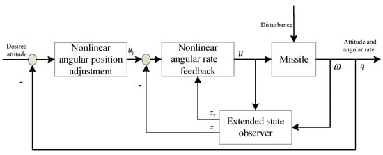
Figure 1.
Structure of attitude control system.
The obtained ESO-based state observer expression is:
where represents the deviation between the estimated roll angle rate and the actual output y. represents the estimation of disturbance in the system and model uncertainty.
For the above model of the rolling channel, the designed control quantity is the linear error feedback of rolling angle rate, namely:
where y represents the output roll angle speed of the system, and represents the control instruction of the roll angle speed.
In order to eliminate the influence of uncertain factors in the loop of the rolling channel, the unknown disturbance observed is compensated, and the control quantity of the inner loop after compensation is:
Thus, the tracking design of roll angle rate in roll channel is realized.
3.4. Stability Analysis
In Equation (23), is the observation value of is the observation value of , and , , which can be obtained from Equations (22) and (23):
Presently, divide the plane into five regions [33] as shown below:
For , respectively, construct the following discontinuous piecewise smooth Lyapunov positive definite functions :
4. Numerical Simulation
The main purpose of attitude controller design is to track the roll speed instruction quickly and accurately, and control the roll speed to achieve the expected roll angle. This section uses Matlab software platform to simulate the missile roll state control and verify the effectiveness of the proposed control method.
In this section, the mass and inertia loss of the aircraft, the deviation of the aircraft structure from the ideal situation, the absolute plus relative deviation of aerodynamic and aerodynamic moment coefficients, and wind disturbance are considered, respectively. In order to verify the adaptive ability of ADRC, a failure mode, namely rudder damage, is also considered.
4.1. Distence Characteristic Analysis
The influence of disturbance factors on rolling attitude control loop is analyzed.
- (1)
- Steerage deviation: The steering effect is the control ability of the steering gear to the course in the missile guidance process. When the missile needs to change the direction at the same angle, the shorter the time required, the smaller the angle the steering gear turns, and the better the steering effect.
- (2)
- Centroid deviation: The center of mass deviation refers to the deviation between the actual center of mass and the theoretical center of mass of the missile, including the longitudinal deviation and the transverse deviation of the center of mass. Since the center of mass does not coincide with the center of reference moment, the coupling of aerodynamic force and attitude system will inevitably affect the attitude system.
- (3)
- Stuck steering gear: In addition to the uncertainty disturbance, the complex and harsh environment is very easy to cause the aging of the structure and some components; thus, causing the failure in the flight process. The common fault of the control surface is that the steering gear is stuck. When the control surface deflects to a certain angle and cannot continue to deflect, it is stuck. After the jamming fault occurs, the control surface will no longer change according to the signal given by the controller. At this time, the rudder can only give a constant signal.
- (4)
- Wind disturbance: Describe the original quantity of wind disturbance factors for wind speed, wind speed is a random quantity, the size and direction are highly, season, climate, location, and the influence of such factors as trimming wind is pointed out that it must be the height of the horizontal wind, usually arrived at a certain height, the wind speed with height increase abruptly, then suddenly decreases, and routine as “wind shear”. Because the time for the aircraft to pass through the shear wind area is generally very short, the effect of the shear wind is similar to the impulse moment.
- (5)
- Drifts error: Because other information of the body comes from navigation and sensor measured data, there will be drifts error and other deviations in the process of long-term storage or multiple experiments, which will also affect the control of rolling accuracy.
4.2. Simulation Conditions
The initial conditions of the simulation experiment in this paper are as follows: the missile is 3000 m above the ground, the initial pitch angle is , the yaw angle is , the roll angle is , the roll angle speed is 3 rad/s, the yaw angle speed is 0 rad/s, and the pitch angle speed is 0 rad/s. The moment of inertia , and of the three axes of the missile are 0.3 kg·m, 8.58 kg·m and 8.58 kg·m respectively, and the sampling time is 0.05 s.
The parameter design of the controller in this paper is: , , .
Based on the given initial simulation conditions, the proposed rolling attitude control method based on ESO is verified by simulation.
4.3. Effectiveness of the Control Method against Multiple Disturbances
Experiment 1: Deviation based on steerage
The rudder torque deflection was set as −10%, and the experimental verification was carried out in the three-axis direction and in combination to test the robustness and stability of the controller.
As can be observed from Figure 2 and Figure 3, when steerage deviation is applied, the attitude tracking error of the roll channel is almost 0, and the control precision of the controller is relatively high, with rapid response and no overshoot. The disturbance is accurately estimated by the extended attitude observer, which successfully compensates the influence of the rudder effect deviation in the model, and verifies the feasibility of the controller.
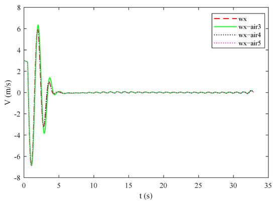
Figure 2.
Change curve of roll angle rate under steerage deviation.
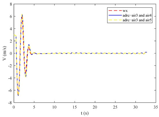
Figure 3.
Change curve of roll angle rate under the combination of two steerage deviations.
As shown in Figure 4 and Figure 5, when a single or integrated steerage deviation is applied, the roll angle deflection of the roll channel can quickly become stable, which successfully illustrates the effectiveness of the extended attitude observer for rudder deflection disturbance estimation.
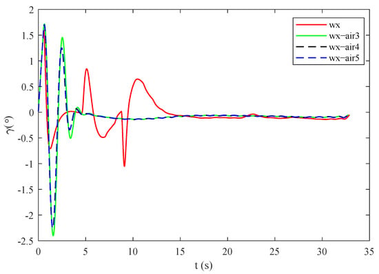
Figure 4.
Roll angle response curve under steerage deviation.
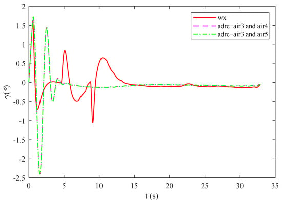
Figure 5.
Roll angle response curve under the combination of two steerage deviation.
Experiment 2: Based on centroid deviation
Considering the variation range of the missile’s three-axis centroid deviation, the centroid deviation is 1% and 2% respectively for comparative experiments. The experimental results are shown in Figure 6 and Figure 7. The controller in this paper can suppress the disturbance of centroid deviation quickly and realize the stable control of diagonal rate.
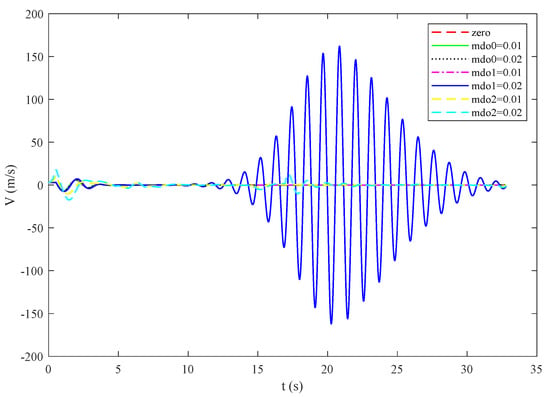
Figure 6.
Change curve of roll angle rate under centroid deviation.
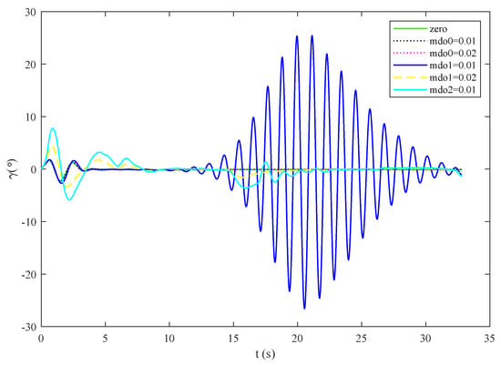
Figure 7.
Roll angle response curve under centroid deviation.
Experiment 3: Based on the steering gear stuck
The effectiveness of the ADRC controller proposed in this paper is studied under the condition that the single actuator is stuck and fails. The experimental results are shown in Figure 8 and Figure 9. It can be observed from the figure that, in the case of steering gear stuck, although there are some fluctuations in the middle, the overall stable control of roll angle can be achieved.
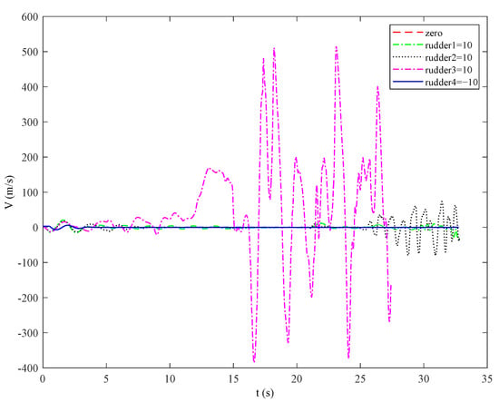
Figure 8.
Change curve of roll angle rate in case of steering gear stuck.
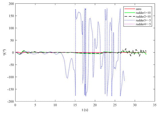
Figure 9.
Roll angle response curve under steering gear stuck.
Experiment 4: Based on wind disturbance
In this section, comparative experiments are carried out when the gust wind is 5 m/s, 10 m/s and 20 m/s, respectively, and the gust wind action height is 2650–2850 m. The experimental results are shown in Figure 10 and Figure 11. It can be observed from the figure that the larger the tangential wind speed is, the greater the amplitude change of the system at the early stage is. At 10 s, the system is near stable, meeting the performance indicators of fast response and effective response to trimming wind disturbance.
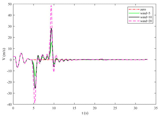
Figure 10.
Change curve of roll angle rate under wind disturbance.
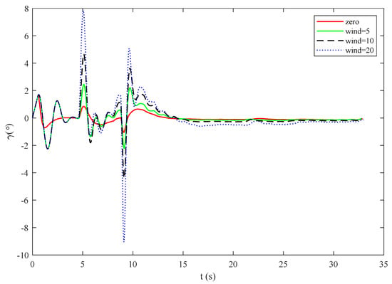
Figure 11.
Roll angle response curve under wind disturbance.
Experiment 5: Based on drifts error
In this section, the control effect of the system with drift error deviation in the range of 0.01/s and 0.1/s is verified by experiments. As can be observed from Figure 12 and Figure 13 below, the system rapidly changes to a stable state after the controller starts acting. It is further verified that the active disturbance rejection controller in this paper can effectively suppress the zero-drift disturbance of the model.
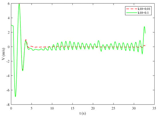
Figure 12.
Change curve of roll angle rate under drifts error condition.
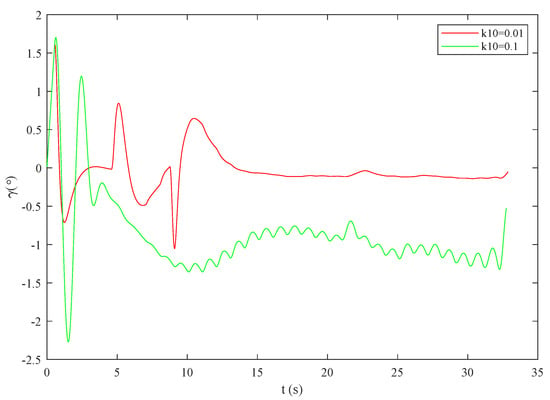
Figure 13.
Roll angle response curve under drifts error.
4.4. Comparison and Analysis
A variety of disturbance factors were applied to the system, including wind disturbance, centroid deviation, rudder effect deviation and dirfts error. Then, the ESO and PID control effects were verified.
The disturbance factors imposed are as follows: the disturbance wind speed is 10 m/s, the centroid deviation is 0.1/s, and the rudder effect deviation is 10.
As can be observed from Figure 14 and Figure 15, under the condition of comprehensive disturbance, the controller proposed in this paper is effective. The influence of disturbance, model deviation and noise is suppressed, and the control effect has no static error. The steady-state performance is obviously better than PID control, and the attitude angle error is smaller than PID control, which significantly improves the missile attitude maneuverability and stability. They satisfy the design requirements of the controller, and further verify the effectiveness of the controller.
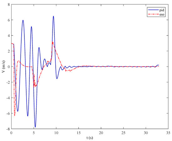
Figure 14.
Comparison of roll angle speed change curve between PID and the controller.
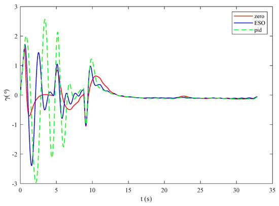
Figure 15.
Comparison of roll angle response curves between PID and the controller.
In order to verify the effectiveness of this algorithm and other adrc algorithms, the system is compared under the same experimental conditions. It can be observed from Figure 16 that compared with other ADRC, the ESO controller proposed in this paper has smaller amplitude of initial disturbance, tends to be stable faster, and has good control performance.
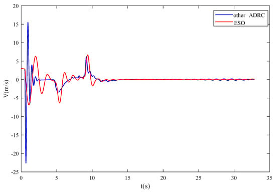
Figure 16.
Comparison of roll angle response curves between different ESO.
5. Conclusions
A roll control algorithm based on extended state observer for small air-to-surface missile was proposed in this paper. The dymamic model of roll channel was established. The internal and external disturbances were estimated and compensated to the state of the system. Still, simulations and comparisons were given to the proposed algorithm to verify its effectiveness. This method provides a reference for the design of related controllers, and has a broad application prospect and practical significance in engineering.
Author Contributions
Conceptualization, X.D., Y.H. and R.J.; methodology, X.D. and J.G.; software, J.G.; data curation, R.J. and Y.H.; writing—original draft preparation, X.D.; writing—review and editing, X.D.; supervision, J.G. All authors have read and agreed to the published version of the manuscript.
Funding
This research was supported in part by the Beijing Natural Science Foundation (4222050) and in part by the National Natural Science Foundation of China (62173030).
Informed Consent Statement
Not applicable.
Data Availability Statement
The data presented in this study are available on request from the corresponding author.
Conflicts of Interest
The authors declare no conflict of interest.
References
- Liu, S.; Xue, M.; Qiu, Y.; Zhou, X.; Zhao, Q. Design of the Missile Attitude Controller Based on the Active Disturbance Rejection Control. J. Aerosp. Technol. Manag. 2022, 14. [Google Scholar] [CrossRef]
- Song, Y.G.; Wang, H.J. Design of flight control system for a small unmanned tilt rotor aircraft. Chin. J. Aeronaut. 2009, 22, 250–256. [Google Scholar]
- Gao, Z.Q.; Huang, Y.; Han, J.Q. An alter-native paradigm for control system design. Proc. IEEE Conf. Control Decis. 2001, 5, 4578–4585. [Google Scholar]
- Han, J.Q. Active Disturbance Rejection Control Technology; National Defense Industry Press: Beijing, China, 2008. [Google Scholar]
- Gong, R.; Sun, R.; Chen, W. Series active disturbance rejection autopilot design for hyper rate projectiles. IEEE Access 2020, 8, 149447–149455. [Google Scholar] [CrossRef]
- Hu, Y.; Guo, J.; Ying, P.; Zeng, G.; Chen, N. Nonlinear control of a single tail tilt servomotor tri-rotor ducted VTOL-UAV. Aerospace 2022, 9, 296. [Google Scholar] [CrossRef]
- Le, R.; Wang, X.; Duan, D.; Wu, Y. Attitude control strategy of airship based on active disturbance rejection controller. Aerosp. Syst. 2021, 4, 7–18. [Google Scholar] [CrossRef]
- Han, J.; Wang, H.; Jiao, G.; Cui, L.; Wang, Y. Research on active disturbance rejection control technology of electromechanical actuators. Electronics 2018, 7, 174. [Google Scholar] [CrossRef]
- Hu, Y.; Guo, J.; Meng, W.; Liu, G.; Xue, W. Longitudinal control for balloon-borne launched solar powered UAVs in near-space. J. Syst. Sci. Complex. 2022, 35, 802–819. [Google Scholar] [CrossRef]
- Guo, B.Z.; Zhao, Z.L. On convergence of non-linear extended state observer for multi-input multi-output systems with uncertainty. IET Control Theory Appl. 2012, 43, 2375–2386. [Google Scholar] [CrossRef]
- Guo, B.Z.; Zhao, Z. On the convergence of an extended state observer for nonlinear systems with uncertainty. Syst. Control Lett. 2011, 60, 420–430. [Google Scholar] [CrossRef]
- Zheng, Q.; Gao, L.Q.; Gao, Z. On validation of extended state observer through analysis and experimentation. J. Dyn. Syst. Meas. Control 2012, 134, 24505. [Google Scholar] [CrossRef]
- Yoo, D.; Yau, S.S.T.; Gao, Z. Optimal fast tracking observer bandwidth of the linear extended state observer. Int. J. Control 2007, 80, 102–111. [Google Scholar] [CrossRef]
- Huang, Y.; Zhang, W.G. Development of active disturbance rejection controller. Control. Theory Appl. 2002, 4, 485–492. [Google Scholar]
- Lei, Z.M.; Lv, Z.D. Nonlinear (adrc) applications in spacecraft attitude control system. Aerosp. Control 2000, 4, 34–39. [Google Scholar]
- Tan, S.; Guo, J.; Zhao, Y.; Zhang, J. Adaptive control with saturation-constrainted observations for drag-free satellites—A set-valued identification approach. Sci. China Inf. Sci. 2021, 64, 202202. [Google Scholar] [CrossRef]
- Yang, F.; Tang, S.-P.; Xue, W.-C.; Guo, J.; Zhao, Y.-L. Extended state filtering with saturation-con-strainted observations and active disturbance rejection control of position and attitude for drag-free satellites. Acta Autom. Sin. 2020, 46, 2337–2349. [Google Scholar]
- Tong, L.; Zhang, S.F.; Yang, H.B.; Zhang, Y.H. Design and verification of small solid rocket control system based on extended state observer. J. Solid Rocket. Technol. 2014, 37, 749–755. [Google Scholar]
- Zhou, L.N.; Tang, G.J.; Li, H.Y. Design of active disturbance rejection controller for spacecraft attitude maneuver. Syst. Eng. Electron. 2007, 12, 2122–2126. [Google Scholar]
- Zhang, Y.H.; Yang, H.B.; Jiang, Z.Y.; Zhang, W.H. Robust flight control method based on general extended state observer. J. Natl. Univ. Def. Technol. 2016, 38, 94–99. [Google Scholar]
- Talole, S.E.; Godbole, A.A.; Kolhe, J.P.; Phadke, S.B. Robust roll autopilot design for tactical missiles. J. Guid. Control Dyn. 2011, 34, 107–117. [Google Scholar] [CrossRef]
- Liu, X.; Cao, Y.; Zhang, Y.; Min, Y.; Jia, Z. Robust stabilization control for attitude angular speeds of strong-soupling sircraft based on a class of ESO. In Proceedings of the 2018 IEEE CSAA Guidance, Navigation and Control Conference (CGNCC), Xiamen, China, 10–12 August 2018; pp. 1–6. [Google Scholar]
- Jin, Y.Q.; Liu, X.D.; Hou, C.Z. Sliding mode control for attitude tracking of flexible spacecraft with parameter uncertainty. Control Theory Appl. 2009, 26, 299–304. [Google Scholar]
- Hu, Q.L.; Ma, G.F.; Jiang, Y.; Liu, Y.Q. Time-varying sliding mode variable structure and active vibration control for attitude maneuver of three-axis stable flexible satellite. Control Theory Appl. 2009, 26, 122–126. [Google Scholar]
- Zhu, C.Y.; Yang, D.; Zhai, K. Active disturbance rejection attitude control for gyro-free large flexible multi-body satellite. Comput. Simul. 2005, 1, 43–47. [Google Scholar]
- Zhang, G.Q.; Ding, J.Z. Adaptive control method for fast maneuver of flexible spacecraft attitude. Space Control Technol. Appl. 2008, 4, 23–27+50. [Google Scholar]
- Gennaro, S.D. Adaptive robust tracking for flexible spacecraft in presence of disturbances. J. Optim. Theory Appl. 1998, 98, 545–568. [Google Scholar] [CrossRef]
- Wang, Z.; Li, J.; Duan, D. Manipulation strategy of tilt quad rotor based on active disturbance rejection contro. Proc. Inst. Mech. Eng. Part J. Aerosp. Eng. 2020, 234, 573–584. [Google Scholar] [CrossRef]
- Qian, X.F.; Ling, R.X.; Zhao, Y.N. Missile Flight Mechanics; Beijing University of Technology Press: Beijing, China, 2000. [Google Scholar]
- Wang, M.G. Design of Guidance and Control System for Air-to-Surface Missile; China Aerospace Press: Beijing, China, 2019. [Google Scholar]
- Hang, J.Q. Extended state observer for a class of uncertain plants. Control Decis. 1995, 10, 85–88. [Google Scholar]
- Song, J.L.; Gan, Z.X.; Hang, J.Q. Study on filtering characteristics of adrc technology. Control Decis. 2003, 18, 110–112. [Google Scholar]
- Hang, J.Q.; Zhang, R. Error analysis of second-order extended state observer. J. Syst. Sci. Math. Sci. 1999, 40, 465–471. [Google Scholar]
- Wang, Y.H.; Yao, Y.; Ma, K.M. Error analysis of second-order extended state observer. J. Jilin Univ. (Eng. Technol. Ed.) 2010, 40, 143–147. [Google Scholar]
Disclaimer/Publisher’s Note: The statements, opinions and data contained in all publications are solely those of the individual author(s) and contributor(s) and not of MDPI and/or the editor(s). MDPI and/or the editor(s) disclaim responsibility for any injury to people or property resulting from any ideas, methods, instructions or products referred to in the content. |
© 2022 by the authors. Licensee MDPI, Basel, Switzerland. This article is an open access article distributed under the terms and conditions of the Creative Commons Attribution (CC BY) license (https://creativecommons.org/licenses/by/4.0/).