Article

A Design for a Wide-Band Antenna Pair Applied for Mobile Terminals at the Sub-6 GHz Band

1
School of Electronic and Information Engineering, Lanzhou Jiaotong University, Lanzhou 730070, China
2
School of Mechanical Engineering, Lanzhou Jiaotong University, Lanzhou 730070, China
3
Engineering Research Center of Integrated Circuit Packaging and Testing, Ministry of Education, Tianshui 741000, China
4
School of Electronic Information and Electrical Engineering, Tianshui Normal University, Tianshui 741000, China
5
Shetang Industry Park, Tianshui Development Zone, Tianshui 741000, China
*
Author to whom correspondence should be addressed.
Appl. Sci. 2023, 13(1), 331; https://doi.org/10.3390/app13010331
Submission received: 2 December 2022 / Revised: 22 December 2022 / Accepted: 22 December 2022 / Published: 27 December 2022

Abstract

:
To meet the requirements of a high transmission rate and strong communication quality for mobile terminals, a planar antenna printed on a 0.8-mm-thick FR-4 substrate is proposed in this paper. The structures are compact, with a size of 23 × 6   mm 2 . The performance of a single antenna pair in a 75 × 35   mm 2 ground plane shows the advantages of both ultra-wide bandwidth and high isolation. The operating frequency of −6 dB is 54% (3.3 GHz–5.9 GHz). To solve the mutual coupling effects exiting in the antenna pair, a hybrid strip defected grounding structure (DGS) is added in the middle of neighboring antenna elements, and good isolation performance of lower than −13 dB is achieved. The evolution and analysis of the proposed antenna pair are given to investigate the operating principle. To verify its practicality, an eight-port antenna system in 150 × 70   mm 2 ground plane is constructed along two frames of the smartphone board. The MIMO antenna system performance is simulated and texted. The results show a bandwidth of 3.4–5.2 GHz (−6 dB), an isolation performance lower than −10 dB, an ECC lower than 0.01, and a total efficiency of 46–84%. In addition, the performance of the antenna system under single handheld conditions is also discussed. The correlation results show that the designed antenna pair has good data transmission and interference resistance capability, which proves that this is an excellent antenna model for application in mobile terminals.

1. Introduction

Wireless communication has entered the fifth-generation mobile communication technology (5G) period. According to the third generation partnership project (3GPP) protocol, the main working operation frequency is divided into the sub-6 GHz (450 MHz–6 GHz) and millimeter-wave (24.25 GHz–52.6 GHz) bands, of which sub-6 GHz has the most development potential in the field of mobile terminal applications. To meet the increasing demand for better communication rates, multiple antenna array technology is being developed, in which a multiple input–multiple output (MIMO) antenna system is one of the research hotspots. For the MIMO systems used in mobile terminals, an antenna with the characteristics of a low profile, compact structure, and excellent radiation performance is essential.
In mobile terminals, there is a trend toward decreasing the size and increasing the number of components. Due to the limitations of physical size, a system with multiple antenna elements not only has a small element size but also has close spacing. Therefore, severe electromagnetic interference is generated in adjacent antenna elements, which is known as the mutual coupling effect of antennas. The mutual coupling effect will damage the independence of the different antennas, that is, isolation and spatial correlation. In addition, it also affects the radiation patterns, gain, and efficiency of the antenna, which makes the channel capacity of the MIMO system reduced. Many decoupling types of research have been proposed, such as neutralization lines (NL) [1,2], decoupling networks [3,4,5], parasitic elements [6,7], defected ground structures (DGS) [8,9], and an electromagnetic band-gap (EBG) [10,11]. There are also decoupling methods that do not require additional decoupling structures, such as orthogonal polarization [12,13] and multiple polarization [14] techniques. Among them, DGS and EBG are more commonly applied in planar antenna array decoupling, due to their trapping properties for electromagnetic waves, which allow surface electromagnetic waves to resonate on the etched grooved surface. In a previous study [15], the resonant currents were concentrated on the edges of radiation patches and the ground plane. By introducing slots on the ground plane, an isolation performance was achieved below −20 dB and showed less impact on impedance matching. In another study [16], multiple DGS were etched on the ground plane for isolation enhancement. Such decoupling structures were noted to be equivalent to band-stop filters, based on a parallel resonator. A modified EBG was used by another group of authors for antenna elements, with an edge-to-edge spacing of 50 mm [17]. Isolation of lower than −23 dB was obtained over the UWB frequency spectrum. Recently, in other research, four- or eight-port MIMO antenna system designs for mobile terminals have been proposed. Those antenna schemes demonstrate compact antennas with decoupling methods, placed on the frames or sides of mobile terminals, that are practical and effective. Resolving the conflict between compact structure and good radiation uncorrelation is a challenge in MIMO antenna system design in the case of mobile terminals.
Previous research [18,19,20,21,22,23,24,25,26,27] presented MIMO antenna system designs applied to mobile terminals at sub-6G bands as shown in Table 1. In [18], an eight-port MIMO system was printed along the inner side of two sideboards. A minimum antenna spacing of 21 mm was used, and a 12.6 × 3.5   mm 2 parasitic patch was placed between adjacent antenna elements, which achieved isolation below −14.5 dB. A MIMO system composed of eight slot antennas on the outside of the metal bezel was designed [19]. With the addition of I-shaped slots on the metal bezel and C-shaped DGS on the ground plane, isolation was achieved below −22 dB. Four loop antenna elements were placed on the quad corners of the mobile phone board [20]. It easily achieved good radiation uncorrelation and isolation of less than −10 dB. In [21], eight antenna elements were evenly placed vertically on the smartphone bezel. Antenna element spacings of 32.375 mm allowed for less than −12 dB isolation. In [22], a quad-port MIMO system with four L-shaped dual-band antennas was proposed. The isolation was lower than −16.5 dB, which was implemented by placing different antennas at a distance of more than one wavelength. An eight-port MIMO system operating at 3.3–3.7 GHz, with an isolation value of less than −15 dB, was proposed by placing eight 4.6 × 5.6   mm 2 antenna elements with equal spacing on the entire bezel [23]. An eight-port MIMO system consisting of loop antennas, with isolation lower than −16 dB, was designed by the authors of [24]. An ultra-wide band of 3.3–5.6 GHz can be obtained, but the single antenna element size is 17.5 × 7.5   mm 2 . Although the above MIMO scheme radiation characteristics meet the requirements of the 5G terminal radiation characteristics, the structures of the antenna systems are not compact enough, leaving limited space for 4G, WiFi, and other modules. In order to keep the balance between physical size and the coupling effect, research on decoupled antenna pairs has increased. Those decoupled antenna pairs using novel structures combine mainly the radiation elements and decoupled models to attain reliable isolation at a certain frequency range. In [25], the authors constructed a compact MIMO system with a high isolation value of −24 dB at a central operating frequency. The chip capacitor was applied between two compact antenna pairs to obtain reliable isolated results but it is only useful for the limitation band. In [26], the authors designed tightly arranged four-element antenna elements with a high isolation value of −11.6 dB. Similarly, inductors and capacitors served as decoupling elements to obtain radiation uncorrelation, which also limited the operating bandwidth of a single frequency at 3.4–3.6 GHz was effective. In [27], the proposed wide-band decoupled antenna pairs covered N77/N78/N79 bands, with isolation better than −15 dB. The DGS on the ground plane and the PE between two elements as decoupled roles was applied. However, to meet the impedance matching, long patch stubs were added to the radiation antennas, and the total size of the antenna pairs was more than 34 × 6   mm 2 .
In this article, a compact planar antenna pair with UWB and high isolation is proposed. The total size of the antenna pairs is 23 × 6   mm 2 , and the inner distance of two adjacent radiation elements with antenna pairs is only 2 mm. The simulated results for the single antenna pair in the 75 × 35   mm 2 ground plane indicate that the −6 dB impedance bandwidth is 54% (3.3 GHz–5.9 GHz), which can cover 2600 MHz of bandwidth of the 5G Sub-6 GHz band. Due to the compact arrangement of the antenna elements, the mutual coupling effect is serious. Therefore, a strip-DGS is added in the middle of the antenna pairs, meaning that a good isolation of lower than −13 dB is realized. Moreover, the eight-port MIMO array in the 150 × 70   mm 2 ground plane comprising the above antenna module is simulated and measured. The results show good isolation, low ECC, and good total efficiency in the context of mobile terminal applications. The radiation performance of the proposed MIMO system is then simulated and measured.

2. Geometry of the Antenna

The structure of the proposed MIMO antenna array and antenna pair is shown in Figure 1. The structures are etched onto an 0.8   mm 2 thick FR-4 substrate with a relative permittivity of 4.3, a relative permeability of 1, and a loss tangent of 0.02. The antenna pair with a size of 23 × 6   mm 2   is a symmetrical structure composed of two radiation elements. To obtain a wide band, the coupling feed method is used. For each antenna element, there are two radiating parts. One is 3 × 5.4   mm 2 on the inner side of the border, acting as a feeding line and major radiation parts. The other part of 10.5 × 6   mm 2 on the outer side plays the role of secondary radiation parts and contributes greatly to improving bandwidth. Besides this, the edge-to-edge distance of two antenna elements is only 2 mm, which leads to a serious mutual coupling in terms of radiation characteristics. Thus, three specially arranged strip DGS, located on the ground plane, are added in the middle of the antenna pairs to enhance isolation. The S-parameter results demonstrate that this is effective for wide-band antenna decoupling.

3. Evolution and Analysis of Antenna Pair

3.1. Evolution

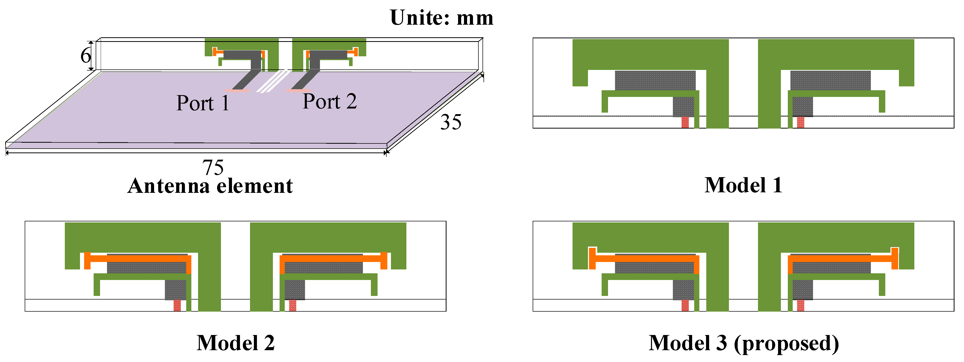
To better understand the operation principle of the proposed antennas, the evolution process of the proposed antenna pair is depicted in Figure 2. The proposed antenna pair with a wide band is realized by three model modifications and the relative changes in reflection coefficients are shown in Figure 3. Due to the symmetrical structure of the antenna pair, the results are obtained when port 1 is excited.
Inspired by the frequency selective surface antenna presented by the authors of [28], this paper attempts to construct different lengths of resonant current paths by controlling the radiating patch to achieve a wideband design. Firstly, a conventional antenna with two L-shaped patches is constructed (Model 1). The simulation results of the reflection coefficients in Figure 3 indicate that Model 1 can resonate at 3.7 GHz, with a band of 700 MHz. In addition, there is the potential for resonance near 5 GHz. It is evident from Figure 4a that the current distribution at 3.7 GHz is strong on the inner area of the long L-shaped patch and the short L-shaped patch. When working at 5 GHz, the current distribution is only concentrated on the short patch. Since the major resonant element has a significant effect on the antenna resonance, the secondary radiation part on the outside is selected to improve the bandwidth. Above the secondary radiation part, the current-sensitive area, which is the middle of the long patch and the short patch, is changed to create new resonant current paths for exciting further band potential. Thus, the T-shaped patch is introduced on the current-sensitive area, and Model 2 is obtained.
One can see from the reflection coefficients that compared to Model 1, the resonant points of Model 2 are shifted to the left, and two resonant points of 4.1 and 5.6 GHz emerge. In addition, the impedance bandwidth is improved, which means that at a low frequency, the wide band from 3.52–4.62 GHz is realized, and at a high frequency, it has an insignificant impedance band from 5.48–5.65 GHz. The current distribution of model 2 in Figure 4b indicates that the resonant current at 4.1 GHz is mainly distributed in a T-shaped patch and a short L-shaped patch. The resonant current at 5.6 GHz is strong in the T-shaped patch and the short L-shaped patch. It can be observed that the addition of a T-shaped patch allows the current path to be shifted on the T-shaped patch and short L-shaped patch and shows great potential for bandwidth expansion between 4.5 and 5.5 GHz. The effect for supporting the resonance of long L-shaped patches is weak. Thus, the long L-shaped patch is the next optimization target. The notch is attempted for the long L-shaped patch to improve impedance-matching for obtaining a wider bandwidth. Along with the above modification, Model 3 is obtained.

3.2. Parameter Analysis

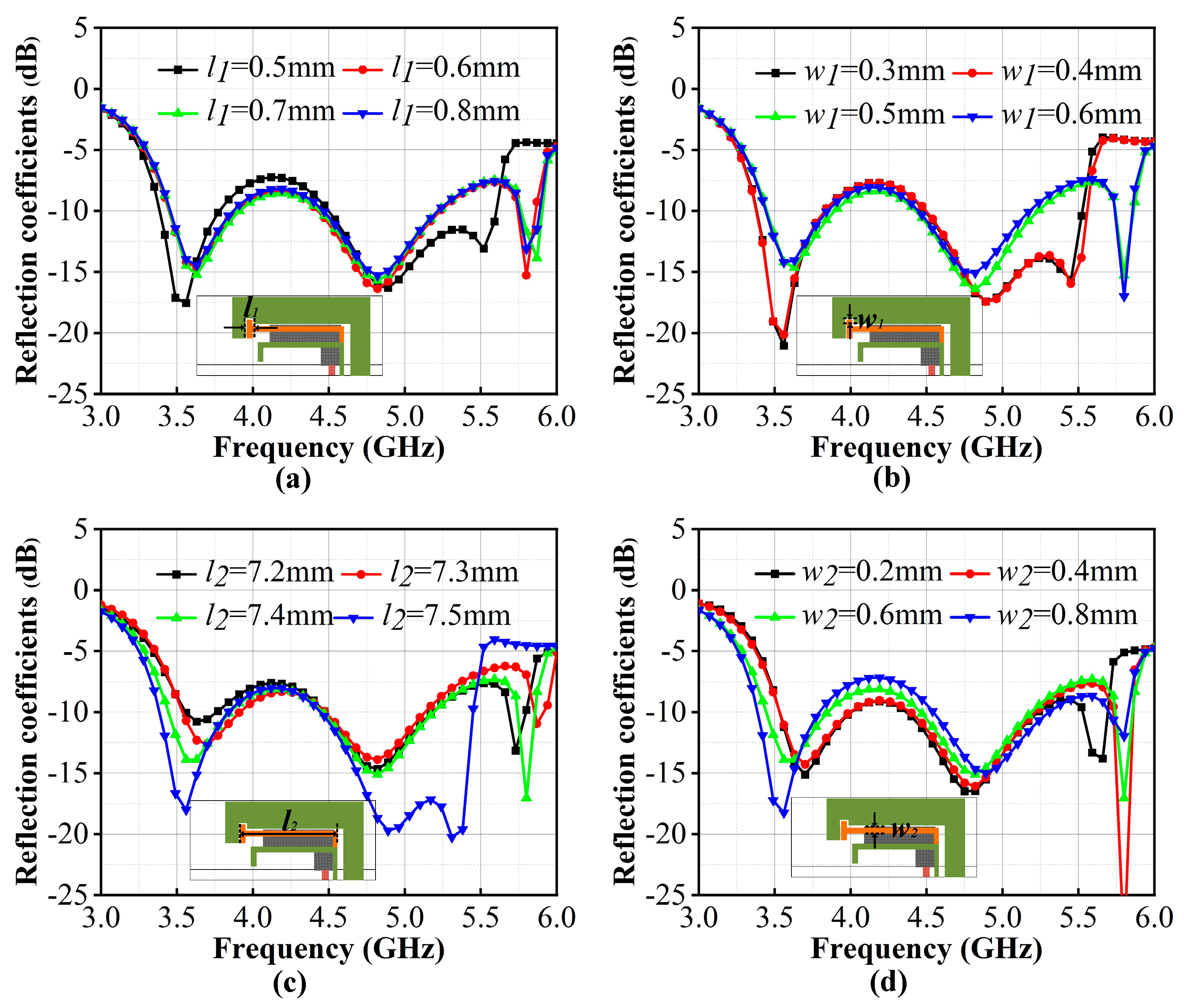
The proposed antenna pair is composed of L-shaped patches, T-shaped patches, and a notch on the long L-shaped patch. The length and width of structures can affect the equivalent impedance of the antenna, which leads to differences in the antenna radiation performance. Among them, the T-shaped patch and notch contribute greatly to bandwidth expansion. Thus, their parameters are discussed below to further investigate the mechanism of the antenna bandwidth.
Figure 5 shows the influence of antenna pair size parameters on the reflection coefficients, which includes l 1 , w 1 of the notch and l 2 , w 2 of the T-shaped patch. One can see from Figure 5a,b that when the notch is connected with the T-shaped patch, where l 1 is smaller than 0.6 mm and   w 1 is smaller than 0.4 mm, the resonant points at 5.6 GHz cannot be generated. When l 1 is larger than 0.6 mm and w 1 is larger than 0.5 mm, it will have less impact on resonant frequency and impedance matching. In conclusion, the notch is an important factor in determining high-frequency resonance. It is only in the presence of the notch that a new resonance, located at 5.5–6.0 GHz, will appear, which is essential to the principle of exciting multiple resonance points in the same plane for expanding the bandwidth. Thus, l 1 = 0.6   mm , and w 1 = 0.5   mm is adopted. From Figure 5c, it can be observed that l 2 influences the impedance matching at low frequency and changes the resonant point at high frequency. The larger the value of l 2 , the better the match at low frequency. However, when l 2 is greater than 7.4 mm, the T-shaped patch can connect to the right side of the notch, and the resonant point exciting at more than 5.5 GHz is destroyed. Figure 5d shows that w 2 has a significant impact on impedance matching for both low frequency and high frequency, and they exhibit opposite trends. With the value of w 2 increasing, the impedance matching at low frequencies becomes better. Conversely, the impedance matching performance at high frequency becomes poor. Therefore, l 2 = 7.4   m m and w 2 = 0.6   m m is adopted.

3.3. Decoupling Structure

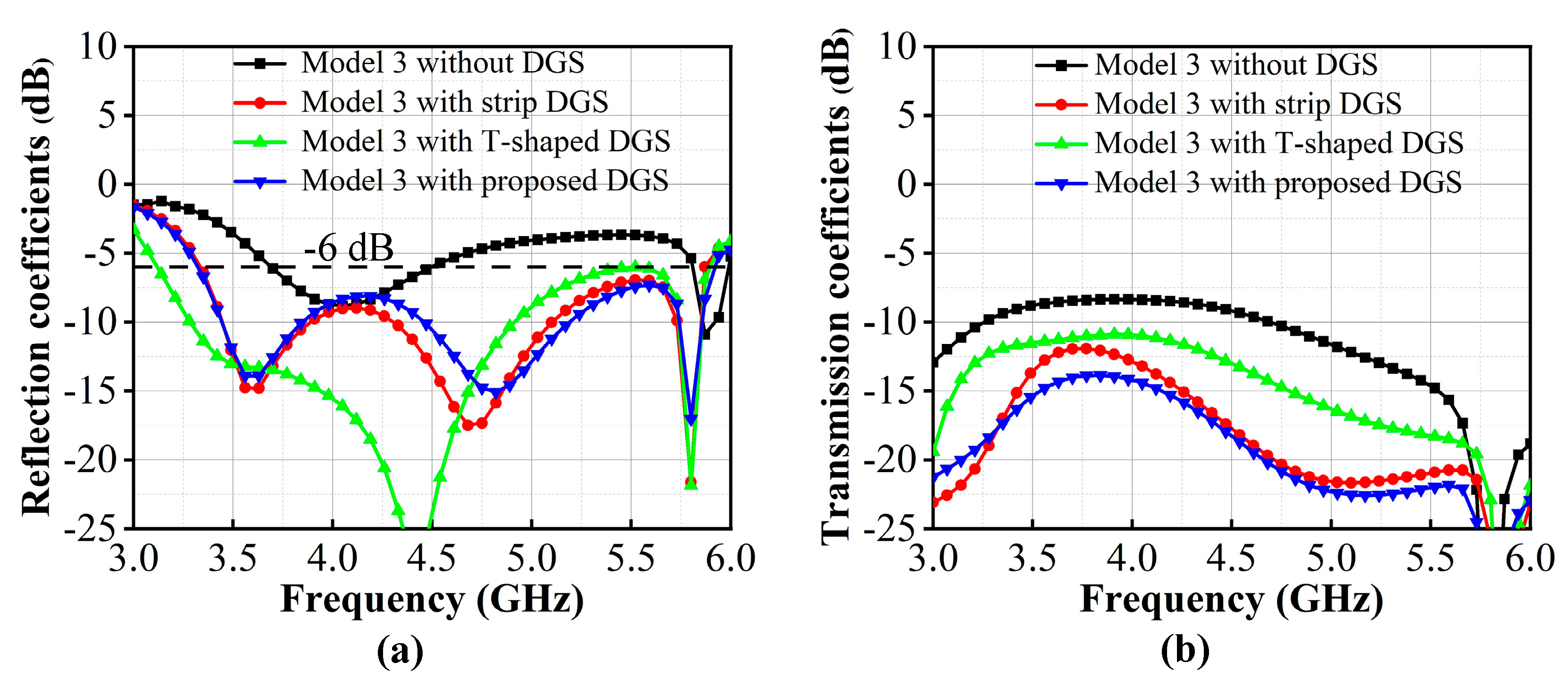
The spacing between the two antenna elements within the proposed antenna pair is only 2 mm. In such a narrow configuration, the mutual coupling effect is inevitable. Figure 6 shows the models of the antenna pairs with different decoupling structures and the impact of the resonant frequency and isolation is depicted in Figure 7. Figure 7b shows that the isolation of antenna pairs without DGS is −8.3 dB, which can be detrimental to antenna efficiency and port independence, resulting in a reduction in channel capacity.
Figure 7b indicates that the worst isolation occurs in the 4–5 GHz band. By observing the surface current distributions in Figure 8, it can be seen that when Port 1 is excited, the propagation of the surface currents on the ground is the main reason for the interference of other antenna elements located on the common ground plane. Thus, the DGS is introduced on the ground plane to enhance the isolation. It can be seen from the S-parameters results of Figure 7 that adding the traditional strip DGS shifts the low-frequency resonance point to the left and improves impedance matching in the desired frequency band. Isolation is also reduced to −11.5 dB. The traditional T-shaped DGS has a significant effect on the bandwidth expansion to lower frequencies, but the high-frequency impedance matching will deteriorate, and its isolation improvement is not obvious for the proposed antenna models. Thus, based on the strip DGS, a new DGS consisting of three interlaced rectangles has been designed. It is evident from Figure 8b that the new DGS can generate new resonant currents in the slots, which effectively block the surface current flow. After adding the proposed structures, the results in Figure 7 not only exhibit good impedance-matching characteristics for wide-band antennas but also effectively improve the isolation, which reduces 6.5 dB compared to isolation without the decoupling structures. Finally, antenna pairs with a wide bandwidth of 54% (3.3 GHz–5.9 GHz) and good isolation values lower than −14.8 dB are achieved.

4. Performance of the Eight-port MIMO System

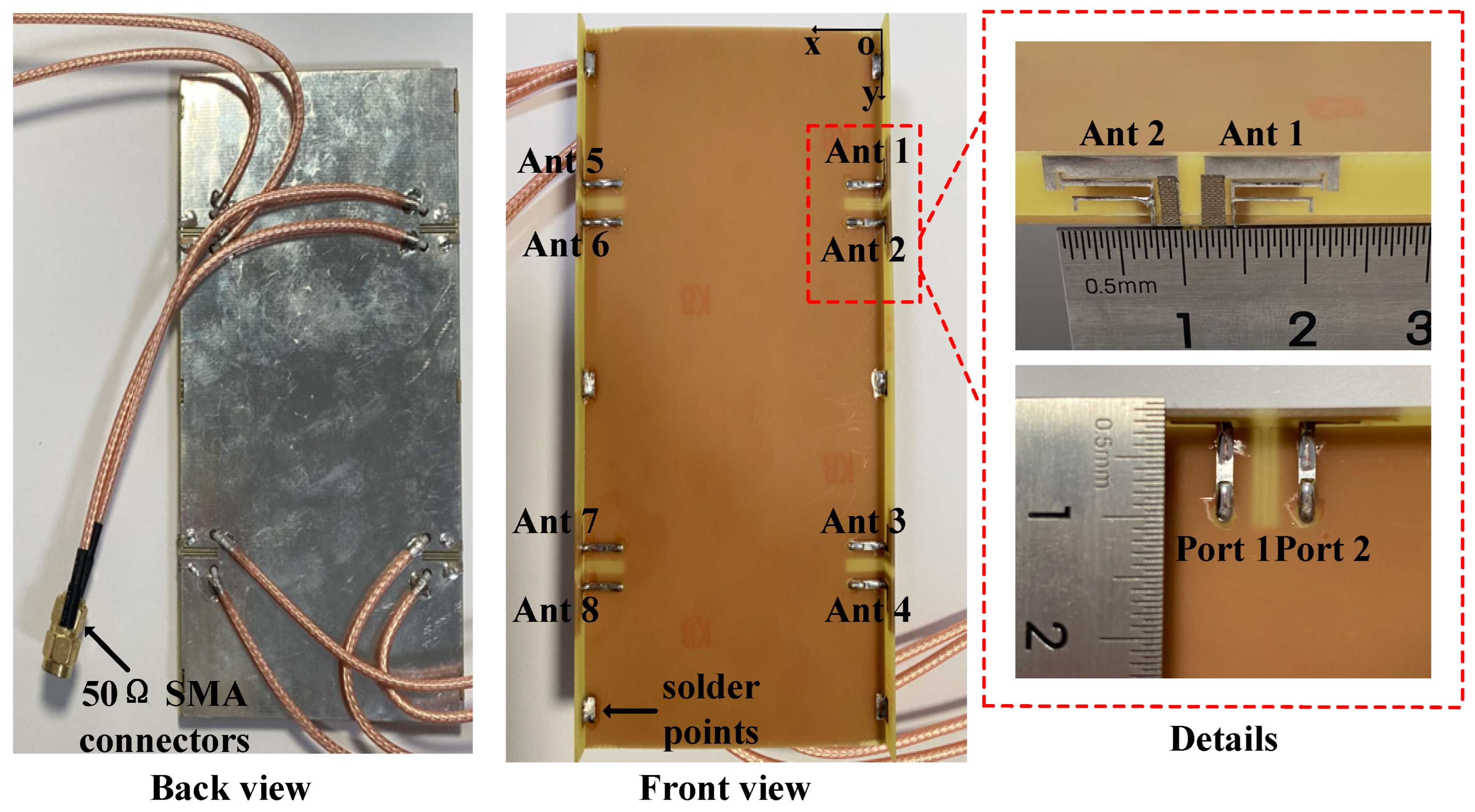
As shown in Figure 9, an eight-port MIMO system composed of four antenna pairs, as proposed above, is constructed. The fabricated MIMO system consists of three parts, including two 150 × 6 × 0.8   mm 3 sides in the vertical direction and one 150 × 75 × 0.8   mm 3 floor in the horizontal direction. The sides and floor are connected by six solder points and eight SMA connectors are added to the ports for antenna performance testing. To demonstrate the effectiveness and practicality of the antenna design, the proposed MIMO system is simulated and measured. Due to the symmetry of the MIMO antenna layout, the simulation and test results are shown for some of the ports.
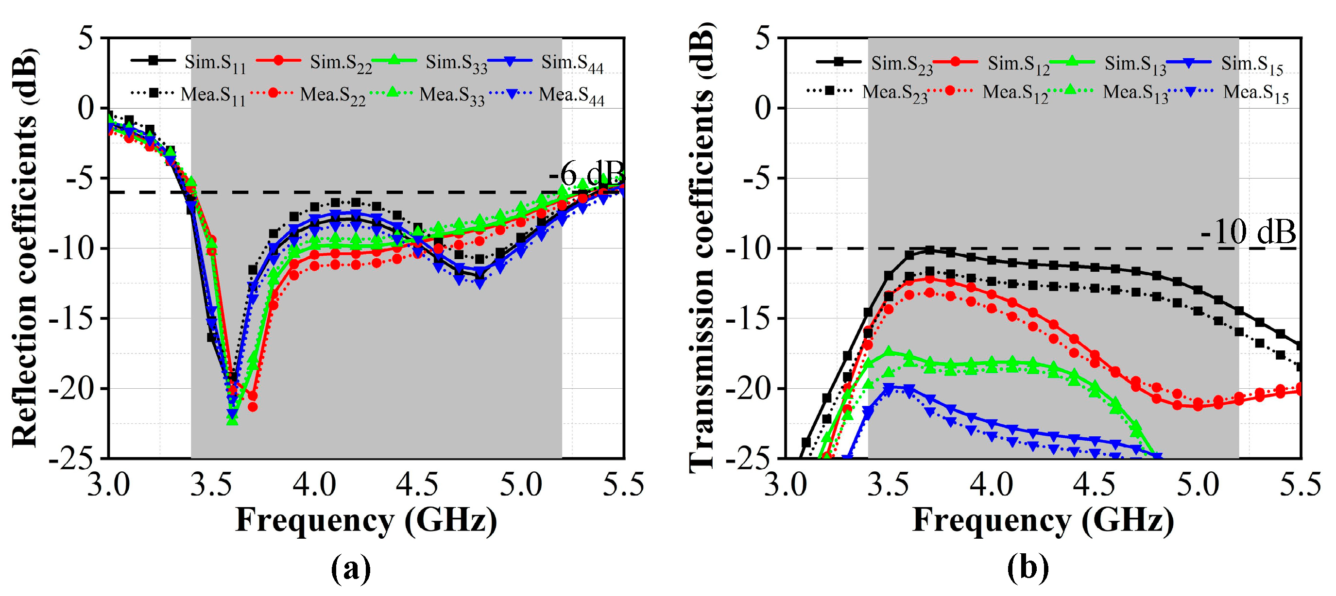
Figure 10 shows the simulated and measured S-parameters results of the proposed eight-port MIMO antenna system. Compared with the S-parameter results of a single antenna pair, the results have some changes. This is due to the influence of the longer surface current path caused by the larger size of the dielectric substrate and the coupling effects from the near antenna elements and the far antenna elements. One can see that there are minor differences in the simulation results and measurement results, which is unavoidable due to measurement errors and the addition of SMA connectors, as well as the addition of solder points. The −6 dB impedance bandwidth depicted in Figure 10a is 3.4–5.2 GHz, which indicates that the proposed MIMO system can work at the N77/N78/N79 bands of 5G communication bands. The isolation depicted in Figure 10b within a common antenna pair is lower than −12.5 dB. Due to the influence of the intersecting polarization directions, the worst isolation exists in Antenna 2 and Antenna 3, and in Antenna 6 and Antenna 7, which still remain below −10 dB.
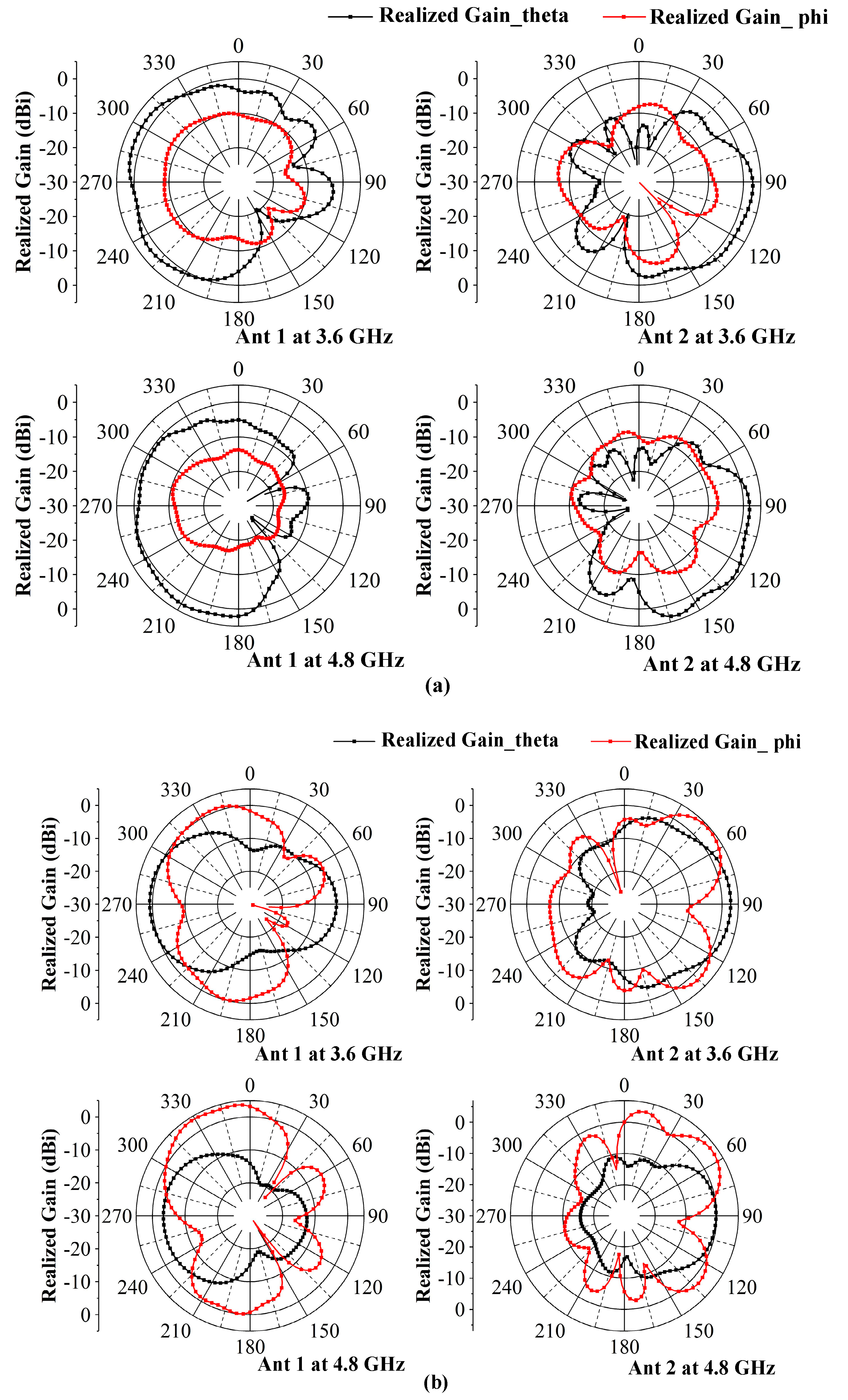
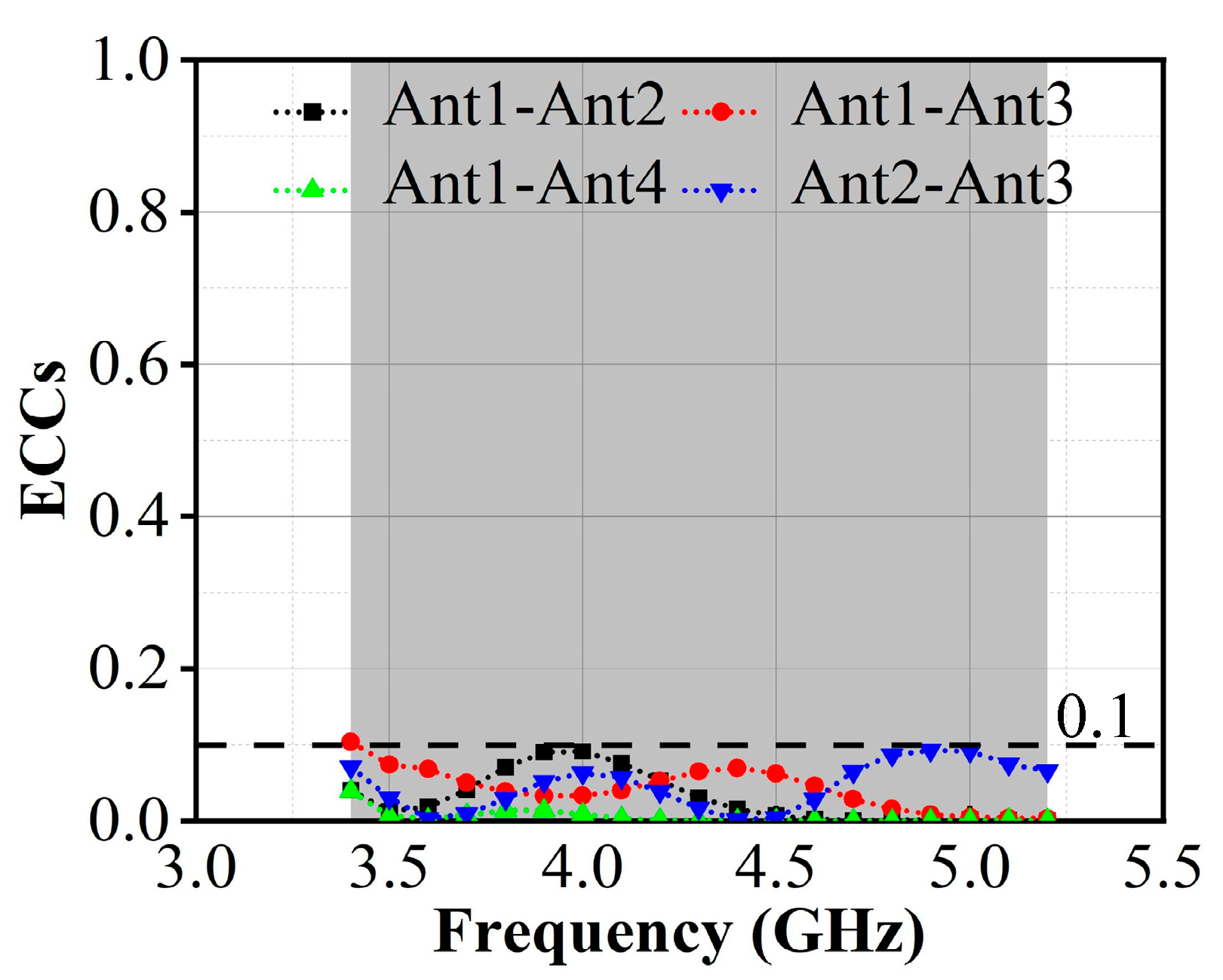
Figure 11 shows the two-dimensional measured radiation patterns of the antenna pair on the MIMO system, observed from 3.6 and 4.8 GHz resonant points. It can be seen that in the xoy plane, the gain of the phi direction is dominant, and in the yoz plane, the gain of the theta direction is dominant. Antenna 1 and Antenna 2 have complementary radiation patterns, which will ensure full coverage of the radiation direction and good radiation diversity. The envelope correlation coefficients (ECC) of the antenna elements are used to evaluate the spatial irrelevance of the antenna radiation. To further verify the coupling suppression ability of the proposed antennas, the ECCs of radiation elements are measured. It can be observed from Figure 12 that the value of both ECCs is lower than 0.1 in the whole of the working frequency bands, which proves that the different antenna radiation patterns of such a MIMO system have good spatial uncorrelation.
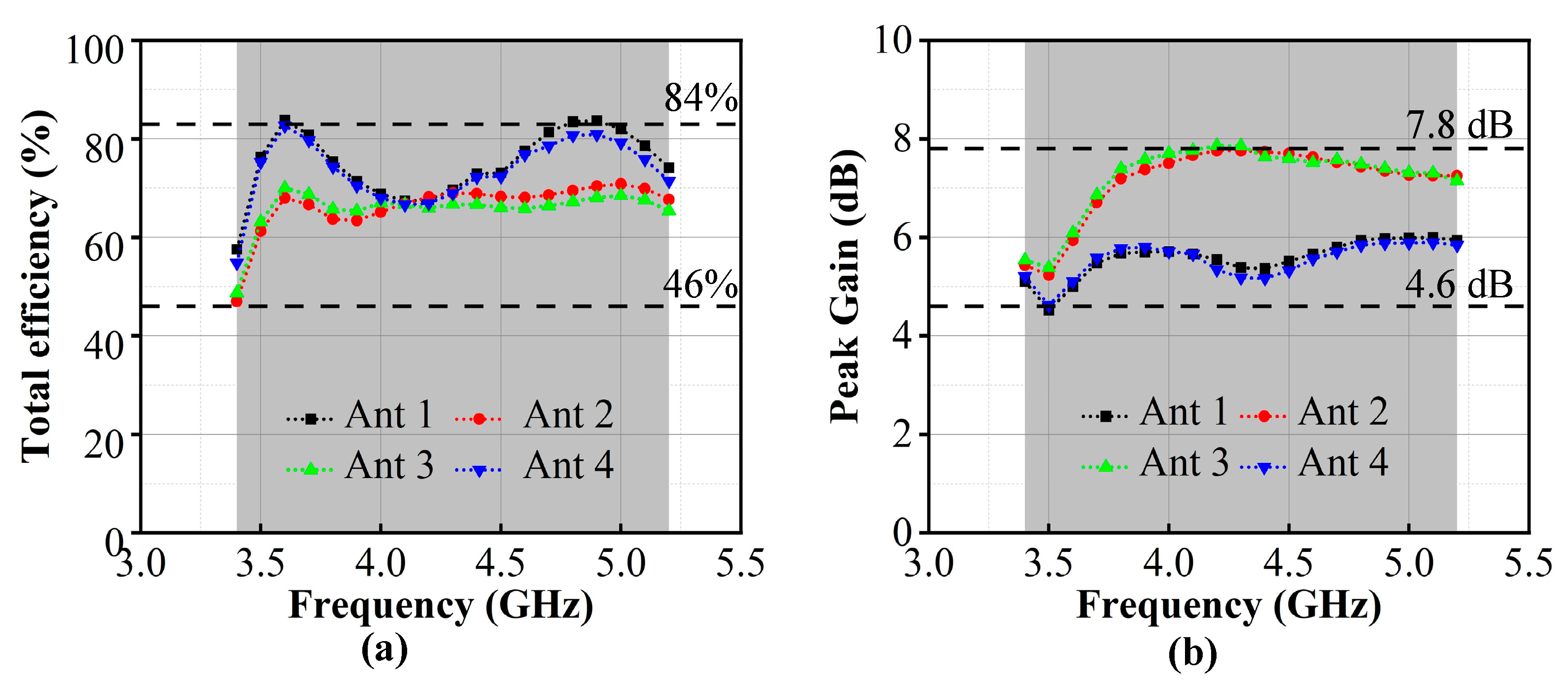
It can be observed from Figure 13a that the total efficiency in the whole working band is better than 46%. The maximum efficiency can reach 84% at 3.6 GHz resonant points. Figure 13b shows that the peak gain of all antennas is higher than 4.6 dB on the working frequency bands. The maximum gain can reach 7.8 dB at 4.3 GHz resonant points. This is enough to ensure that the proposed MIMO system has sufficient power to transmit information and meet the communication needs of the mobile terminals.
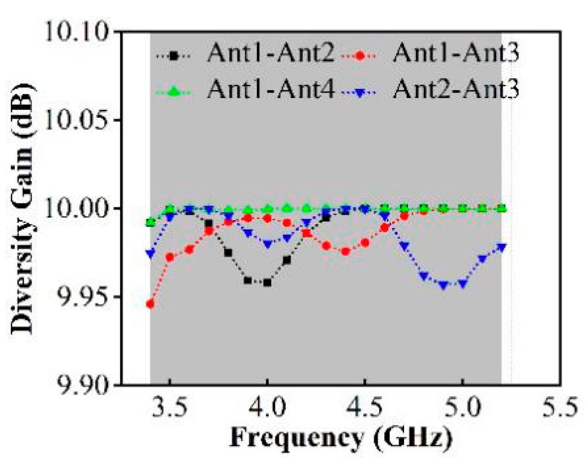
The diversity gain (DG) reflects the ability to differentiate independent multipath signals on MIMO antenna systems, which can be calculated from the ECCs in Equation (1):
D G m , n = 10 1 E C C m , n 2
It can be seen in Figure 14 that in the 3.4–5.2 GHz working bands, the value of DG is better than 9.99 dB.
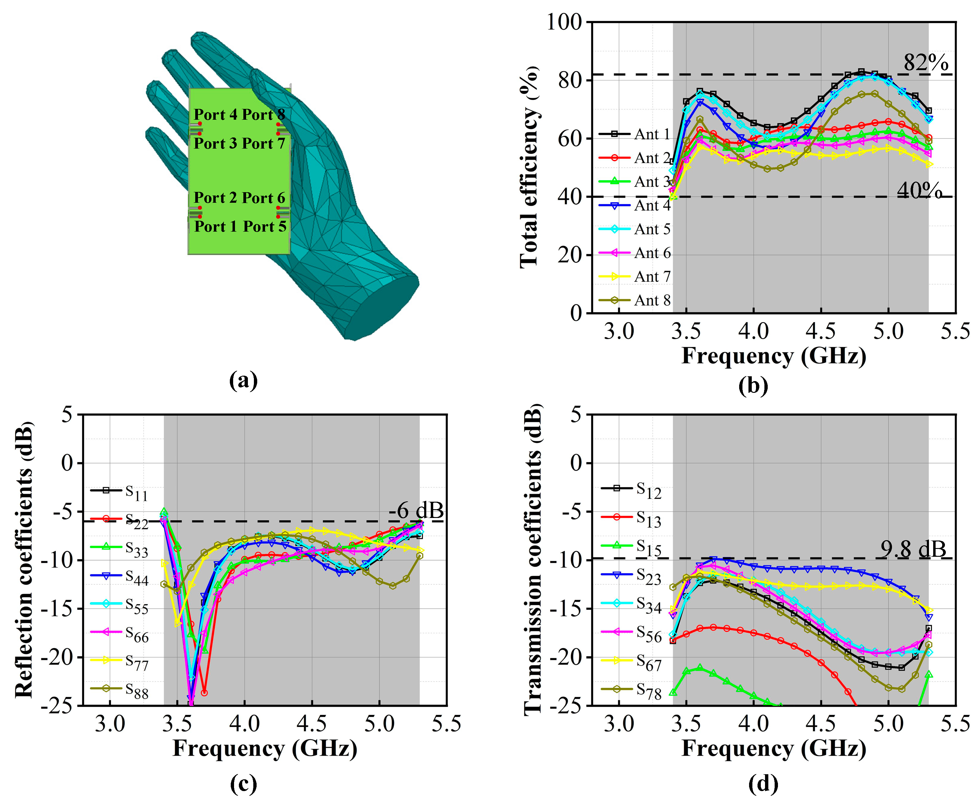
To verify the practicality and robustness of the proposed MIMO system as a mobile terminal antenna system, the MIMO system model, depicted for the right hand, is constructed as shown in Figure 15a. Among them, ports 5–8 are close to the inside of the hand, and radiation performance is more likely to be influenced by the hand. Figure 15b indicates that compared with the MIMO system model in the free space, the efficiency of handheld models is slightly reduced; the efficiency can be above 40% and the maximum value can reach 82%. The performances of the S-parameters are similar. Figure 15c,d indicates the −6 dB impedance bandwidth is from 3.4 GHz–5.3 GHz and the isolation is less than −9.8 dB. The MIMO system can still achieve wide bandwidth and good coupling reduction under handheld conditions.

5. Conclusions

In this article, an antenna pair for application in mobile terminals is designed. The proposed 23 × 6   mm 2 antenna pair in the 75 × 35   mm 2 ground plane can realize 54% (3.3 GHz–5.9 GHz) of bandwidth with −6 dB impedance matching which the N77/N78/N79/WLAN 5G bands of 5G communication terminals can be covered. With the action of a hybrid strip DGS, the inevitable mutual coupling effect in the antenna pair can be effectively solved and the isolation is lower than −13 dB in the whole working band. In the constituted eight-port MIMO system with a 150 × 70   mm 2 ground plane, the antenna still performs well, with an ECC below 0.1, a gain above 4.6, efficiency above 46%, and good omnidirectionality in the radiation patterns. In addition, the MIMO system can maintain similar performance with the above results under single handheld conditions, which proves it to be an excellent antenna model for 5G communication terminal devices.

Author Contributions

Conceptualization, Y.H., K.D. and Y.W.; methodology, Y.H., K.D.; software, Y.H., L.Z.; validation, Y.H., K.D.; investigation, Y.H., X.K.; writing—original draft preparation, Y.H.; writing—review and editing, Y.H., K.D.; visualization, Y.H., L.Z. and X.K.; supervision, Y.W. All authors have read and agreed to the published version of the manuscript.

Funding

This research was funded as part of the development of high photoelectric conversion efficiency Si_PEDOT:PSS: PSS heterojunction solar cells, Youth Science Foundation of Lanzhou Jiaotong University, grant number 2021025.

Institutional Review Board Statement

Not applicable.

Informed Consent Statement

Not applicable.

Data Availability Statement

Not applicable.

Acknowledgments

The authors would like to thank the very valuable comments given by the anonymous reviewers. The authors thank Kang Xiaoming for his contribution to this paper.

Conflicts of Interest

The authors declare no conflict of interest. The funders had no role in the design of the study; in the collection, analyses, or interpretation of data; in the writing of the manuscript; or in the decision to publish the results.

References

  1. Mishra, M.; Chaudhuri, S.; Kshetrimayum, R.S.; Chel, H. Low mutual coupling six-port planar antenna for the MIMO applications. Int. J. RF Microw. Comput. Aided Eng. 2020, 30, e22439. [Google Scholar] [CrossRef]
  2. Kumar, P.; Ali, T.; Mm, M.P. Characteristic Mode Analysis-Based Compact Dual Band-Notched UWB MIMO Antenna Loaded with Neutralization Line. Micromachines 2022, 13, 1599. [Google Scholar] [CrossRef]
  3. Zhang, Y.; Ye, Q.; Pedersen, G.F.; Zhang, S. A Simple Decoupling Network With Filtering Response for Patch Antenna Arrays. IEEE Trans. Antennas Propag. 2021, 69, 7427–7439. [Google Scholar] [CrossRef]
  4. Zhao, L.; Yeung, L.K.; Wu, K. A Coupled Resonator Decoupling Network for Two-Element Compact Antenna Arrays in Mobile Terminals. IEEE Trans. Antennas Propag. 2014, 62, 2767–2776. [Google Scholar] [CrossRef]
  5. Xu, K.; Luyen, H.; Behdad, N. A Decoupling and Matching Network Design for Single- and Dual-Band Two-Element Antenna Arrays. IEEE Trans. Microw. Theory Tech. 2020, 68, 3986–3999. [Google Scholar] [CrossRef]
  6. Tran, H.H.; Nguyen-Trong, N. Performance Enhancement of MIMO Patch Antenna Using Parasitic Elements. IEEE Access 2021, 9, 30011–30016. [Google Scholar] [CrossRef]
  7. Li, Z.; Du, Z.; Takahashi, M.; Saito, K.; Ito, K. Reducing Mutual Coupling of MIMO Antennas With Parasitic Elements for Mobile Terminals. IEEE Trans. Antennas Propag. 2012, 60, 473–481. [Google Scholar] [CrossRef]
  8. Wang, W.; Wu, Y.; Wang, W.; Yang, Y. Isolation Enhancement in Dual-Band Monopole Antenna for 5G Applications. IEEE Trans. Circuits Syst. II Express Briefs 2021, 68, 1867–1871. [Google Scholar] [CrossRef]
  9. Hu, W.; Qian, L.; Wen, L.; Yang, X.; Yin, Y. Compact dual-band antenna based on CRLH-TL for WWAN/LTE terminal applications. Int. J. RF Microw. Comput. Aided Eng. 2019, 29, e21587. [Google Scholar] [CrossRef]
  10. Alibakhshikenari, M.; Virdee, B.S.; See, C.H.; Abd-Alhameed, R.; Hussein Ali, A.; Falcone, F.; Limiti, E. Study on isolation improvement between closely-packed patch antenna arrays based on fractal metamaterial electromagnetic bandgap structures. IET Microw. Antennas Propag. 2018, 12, 2241–2247. [Google Scholar] [CrossRef]
  11. Jiang, T.; Jiao, T.; Li, Y. Array Mutual Coupling Reduction Using L-Loading E-Shaped Electromagnetic Band Gap Structures. Int. J. Antennas Propag. 2016, 2016, 6731014. [Google Scholar] [CrossRef] [Green Version]
  12. Sun, L.; Feng, H.; Li, Y.; Zhang, Z. Compact 5G MIMO Mobile Phone Antennas With Tightly Arranged Orthogonal-Mode Pairs. IEEE Trans. Antennas Propag. 2018, 66, 6364–6369. [Google Scholar] [CrossRef]
  13. Xu, H.; Gao, S.S.; Zhou, H.; Wang, H.; Cheng, Y. A Highly Integrated MIMO Antenna Unit: Differential/Common Mode Design. IEEE T. Antennas Propag. 2019, 67, 6724–6734. [Google Scholar] [CrossRef]
  14. Zhong, X.; Chen, L.; Shi, Y.; Shi, X. Design of Multiple-Polarization Transmitarray Antenna Using Rectangle Ring Slot Elements. IEEE Antennas Wirel. Propag. Lett. 2016, 15, 1803–1806. [Google Scholar] [CrossRef]
  15. Khurshid, A.; Dong, J.; Ahmad, M.S.; Shi, R. Optimized Super-Wideband MIMO Antenna with High Isolation for IoT Applications. Micromachines 2022, 13, 514. [Google Scholar] [CrossRef]
  16. Chiu, C.; Cheng, C.; Murch, R.D.; Rowell, C.R. Reduction of Mutual Coupling Between Closely-Packed Antenna Elements. IEEE Trans. Antennas Propag. 2007, 55, 1732–1738. [Google Scholar] [CrossRef]
  17. Fadehan, G.A.; Olasoji, Y.O.; Adedeji, K.B. Mutual Coupling Effect and Reduction Method with Modified Electromagnetic Band Gap in UWB MIMO Antenna. Appl. Sci. 2022, 12, 12358. [Google Scholar] [CrossRef]
  18. Zhang, C.; Chen, Z.; Shi, X.; Yang, Q.; Dong, G.; Wei, X.; Liu, G. A Dual-Band Eight-Element MIMO Antenna Array for Future Ultrathin Mobile Terminals. Micromachines 2022, 13, 1267. [Google Scholar] [CrossRef]
  19. Gao, Y.; Wang, J.; Wang, X.; Shao, R. Miniaturized MIMO Antenna Array with High Isolation for 5G Metal-Frame Smartphone Application. Micromachines 2022, 13, 1064. [Google Scholar] [CrossRef]
  20. Rafique, U.; Khan, S.; Ahmed, M.M.; Kiani, S.H.; Abbas, S.M.; Saeed, S.I.; Alibakhshikenari, M.; Dalarsson, M. Uni-Planar MIMO Antenna for Sub-6 GHz 5G Mobile Phone Applications. Appl. Sci. 2022, 12, 3746. [Google Scholar] [CrossRef]
  21. Kiani, S.H.; Marey, M.; Savci, H.S.; Mostafa, H.; Rafique, U.; Khan, M.A. Dual-Band Multiple-Element MIMO Antenna System for Next-Generation Smartphones. Appl. Sci. 2022, 12, 9694. [Google Scholar] [CrossRef]
  22. Huang, J.; Dong, G.; Cai, J.; Li, H.; Liu, G. A Quad-Port Dual-Band MIMO Antenna Array for 5G Smartphone Applications. Electronics 2021, 10, 542. [Google Scholar] [CrossRef]
  23. Abdullah, M.; Altaf, A.; Anjum, M.R.; Arain, Z.A.; Jamali, A.A.; Alibakhshikenari, M.; Falcone, F.; Limiti, E. Future Smartphone: MIMO Antenna System for 5G Mobile Terminals. IEEE Access 2021, 9, 91593–91603. [Google Scholar] [CrossRef]
  24. Alja’Afreh, S.S.; Altarawneh, B.; Alshamaileh, M.H.; Almajali, E.R.; Hussain, R.; Sharawi, M.S.; Xing, L.; Xu, Q. Ten Antenna Array Using a Small Footprint Capacitive-Coupled-Shorted Loop Antenna for 3.5 GHz 5G Smartphone Applications. IEEE Access 2021, 9, 33796–33810. [Google Scholar] [CrossRef]
  25. Ye, Y.; Zhao, X.; Wang, J. Compact High-Isolated MIMO Antenna Module With Chip Capacitive Decoupler for 5G Mobile Terminals. IEEE Antennas Wirel. Propag. Lett. 2022, 21, 928–932. [Google Scholar] [CrossRef]
  26. Deng, C.; Liu, D.; Lv, X. Tightly Arranged Four-Element MIMO Antennas for 5G Mobile Terminals. IEEE Trans. Antennas Propag. 2019, 67, 6353–6361. [Google Scholar] [CrossRef]
  27. Hei, Y.; He, J.; Li, W. Wideband Decoupled 8-Element MIMO Antenna for 5G Mobile Terminal Applications. IEEE Antennas Wirel. Propag. Lett. 2021, 20, 1448–1452. [Google Scholar] [CrossRef]
  28. Alwareth, H.; Ibrahim, I.M.; Zakaria, Z.; Al-Gburi, A.; Ahmed, S.; Nasser, Z.A. A Wideband High-Gain Microstrip Array Antenna Integrated with Frequency-Selective Surface for Sub-6 GHz 5G Applications. Micromachines 2022, 13, 1215. [Google Scholar] [CrossRef]
Figure 1. The structure of the proposed MIMO antenna array and antenna pair. (a) Geometry and parameters of the proposed eight-port MIMO. (b) Geometry and parameters of the proposed antenna pair.
Applsci 13 00331 g001
Figure 2. The evolution of the antenna pairs.
Applsci 13 00331 g002
Figure 3. Reflection coefficients of different antenna models.
Applsci 13 00331 g003
Figure 4. Simulated current distribution; (a) current distribution of Model 1; (b) current distribution of Model 2.
Applsci 13 00331 g004
Figure 5. Influence of the antenna pair size parameters on reflection coefficients: (a) l 1 is the variable; (b) w 1 is the variable; (c) l 2 is the variable; (d) w 2 is the variable.
Applsci 13 00331 g005
Figure 6. Antenna pair with different DGS. (a) Model 3 without DGS. (b) Model 3 with strip DGS. (c) Model 3 with a T-shaped DGS. (d) Model 3 with the proposed DGS.
Applsci 13 00331 g006
Figure 7. S-parameters of the antenna pair with different DGS. (a) Reflection coefficients. (b) Transmission coefficients.
Applsci 13 00331 g007
Figure 8. Comparisons of the antenna pair surface current distributions with and without a decoupling structure. (a) Surface currents at 4.0 GHz. (b) Surface currents at 5.5 GHz.
Applsci 13 00331 g008
Figure 9. Photograph of the proposed eight-port MIMO system.
Applsci 13 00331 g009
Figure 10. Simulated and measured S-parameters of a proposed MIMO system. (a) Reflection coefficients. (b) Transmission coefficients.
Applsci 13 00331 g010
Figure 11. Measured two-dimensional radiation patterns of antenna elements. (a) Results of Antenna 1 and Antenna 2 in the xoy plane. (b) Results of Antenna 1 and Antenna 2 in the yoz plane.
Applsci 13 00331 g011
Figure 12. Measured ECCs of the proposed MIMO system.
Applsci 13 00331 g012
Figure 13. Measured total efficiency and peak gain of the proposed MIMO system. (a) Total efficiency. (b) Peak gain.
Applsci 13 00331 g013
Figure 14. Calculated diversity gain.
Applsci 13 00331 g014
Figure 15. Simulation results of the proposed MIMO system in the handheld position. (a) Antenna model in the right hand. (b) Total efficiency. (c) Reflection coefficients. (d) Transmission coefficients.
Applsci 13 00331 g015
Table 1. Comparisons of the sub-6G MIMO terminal antenna designs.
Ref.Antenna PairsElement Size
( mm 2 )
Decoupling
Methods
Frequency
(GHz)
Isolation
(dB)
ECCTotal
Efficiency (%)
Ports
[18] 39 × 4.2 PE3.4–3.6/4.8–5.0
(−10 dB)
<−14.5<0.04-8
[19]× 6.78 × 3.8 DGS4.4–5.0
(−6 dB)
<−22<0.04950–738
[20]× 12 × 14.5 -3–4.28
(−6 dB)
<−10<0.0270–954
[21]× 8 × 4 -3.4–3.6/5.1–5.7
(−10 dB)
<−14<0.0258–62/68–748
[22]× 6.5 × 6 -3.4–3.6
(−10 dB)
<−10<0.05565–8010
[23]× 4.6 × 5.6 -3.3–3.7
(−6 dB)
<−15<0.150–758
[24]× 14.9 × 7 -3.4–3.6/4.8–5.0
(−10 dB)
<−16.5<0.0174–85/70–824
[25] 20 × 6.2 PEs3.4–3.6
(−10 dB)
<−17<0.1-4
[26] 49.5 × 6 NLs2.3–2.4/3.3–3.6
(−6 dB)
<−15<0.1547–738
[27] 47 × 6 Pes
and DGS
3.3–5.95
(−6 dB)
<−15<0.1147–788
Pro. 23 × 6 DGS3.4–5.2
(−6 dB)
<−10<0.146–848
Disclaimer/Publisher’s Note: The statements, opinions and data contained in all publications are solely those of the individual author(s) and contributor(s) and not of MDPI and/or the editor(s). MDPI and/or the editor(s) disclaim responsibility for any injury to people or property resulting from any ideas, methods, instructions or products referred to in the content.