
Research on the Interaction between the Pile and Shield Machine in the Process of Cutting a Reinforced Concrete Pile Foundation


Abstract
1. Introduction
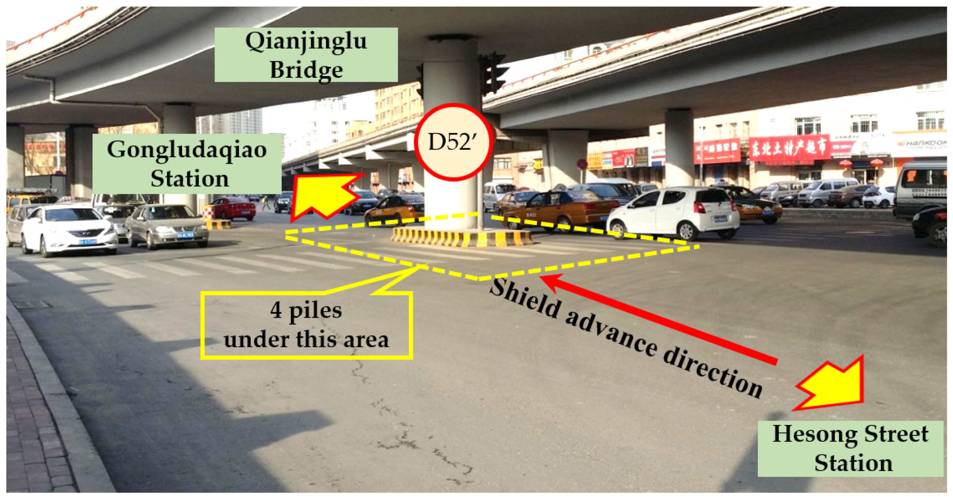
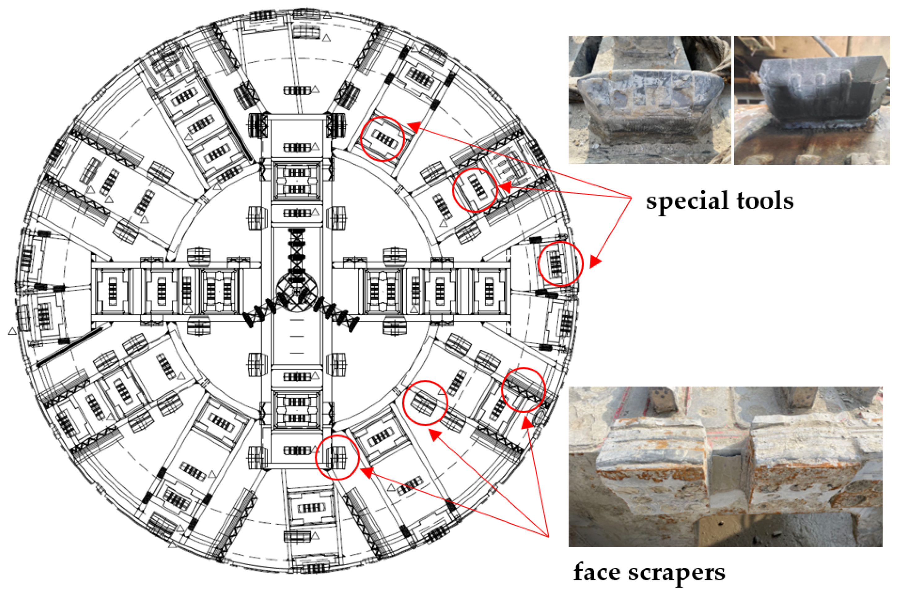
2. Project Overview
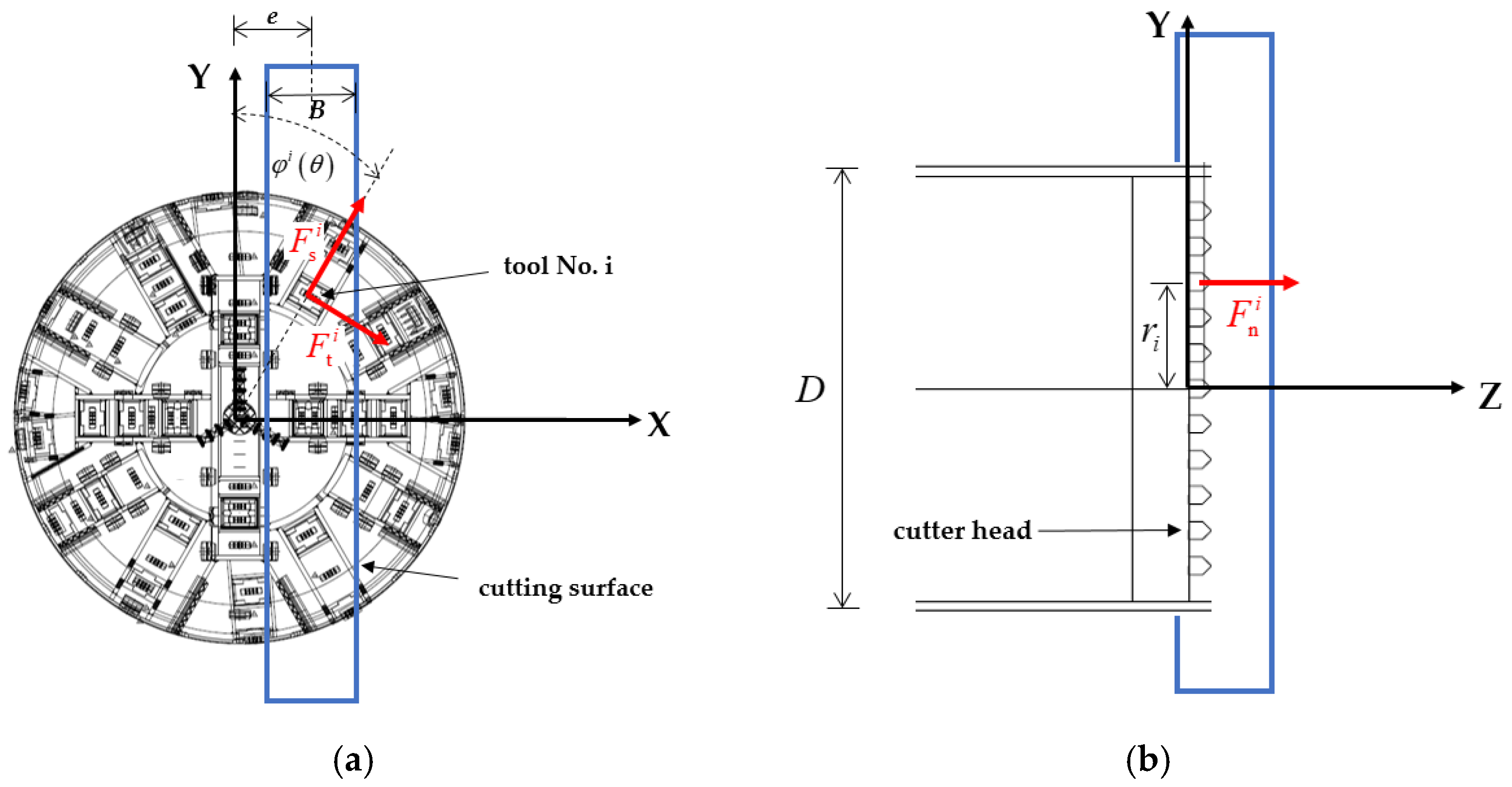
3. Calculation Model
4. Model Verification
4.1. Cutting Force of a Single Tool
- (1)
- The material strength model is described by the normalized equivalent stress, as in Equation (5) and Figure 5a:
- (2)
- Damage of the HJC model is accumulated from both the equivalent plastic strain and plastic volumetric strain, as in Equation (6) and Figure 5b:
- (3)
- The relationship between the volume strain and actual pressure in the HJC model is expressed through equation of state and separated into three phases, as shown in Figure 5c. The first phase (OA) is linear elastic and expressed as follows:
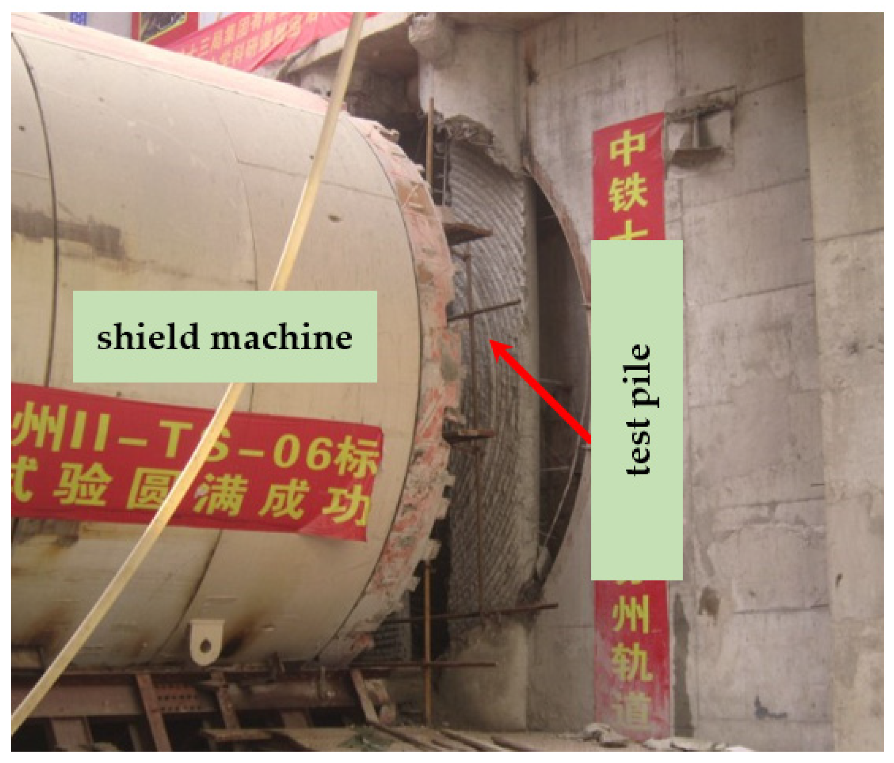
4.2. Field Test of Cutting Piles
4.3. Comparison of the Interaction Force
5. Engineering Practice
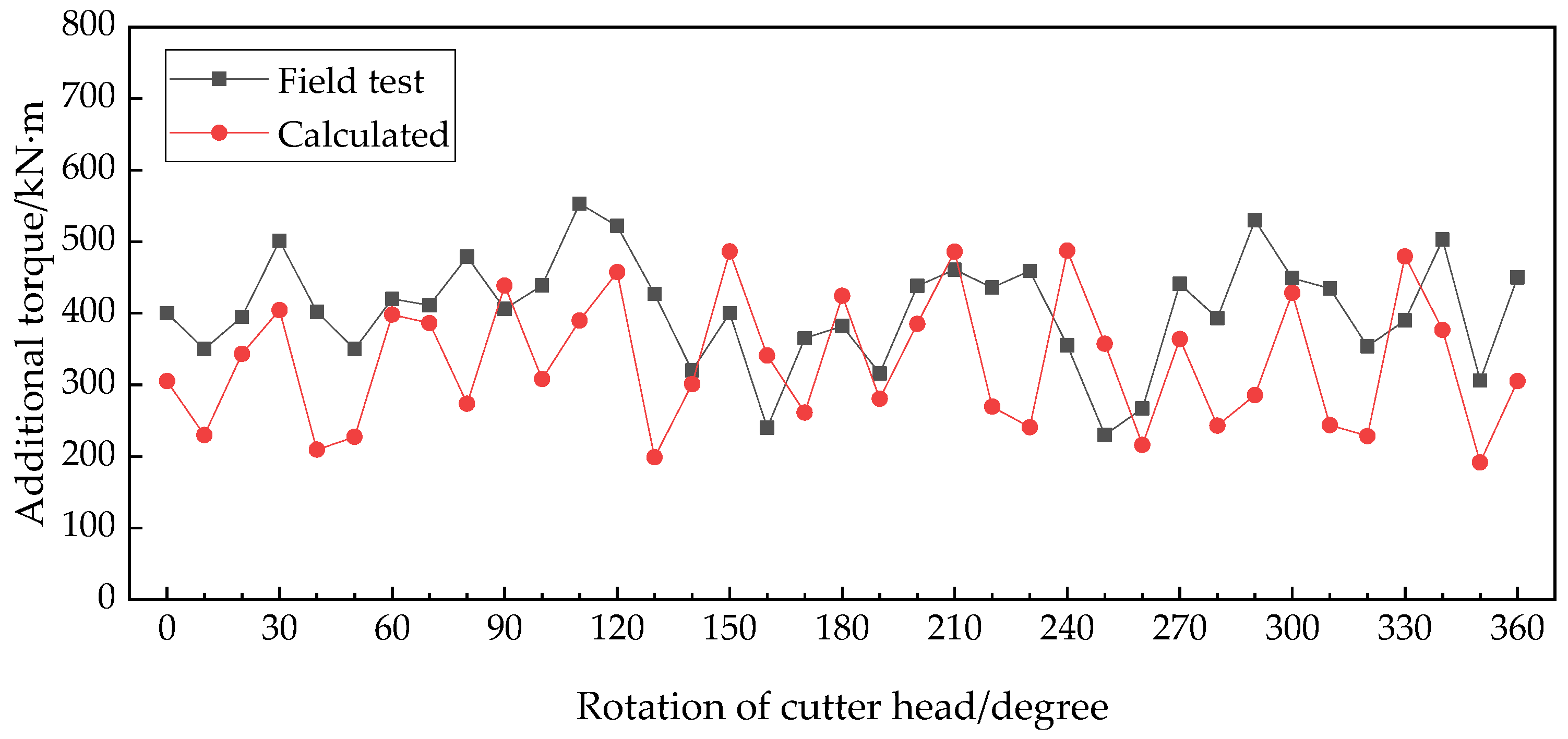
5.1. Additional Torque at Different Rotation Angles
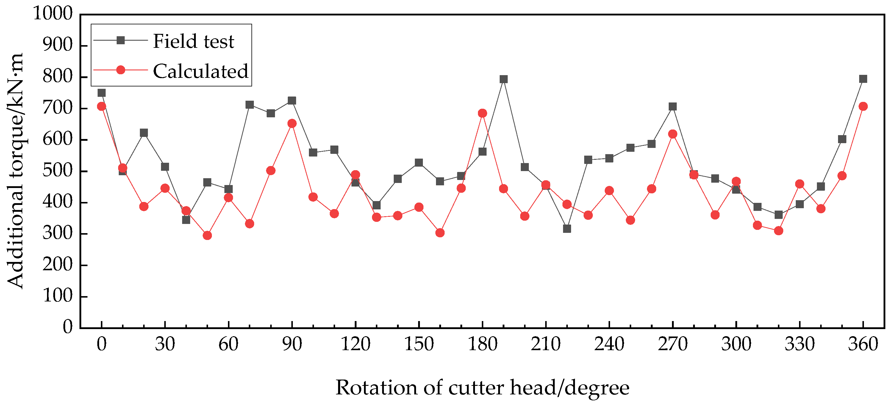
5.2. Additional Torque at Different Cutting Distances
6. Parametric Study and Discussions
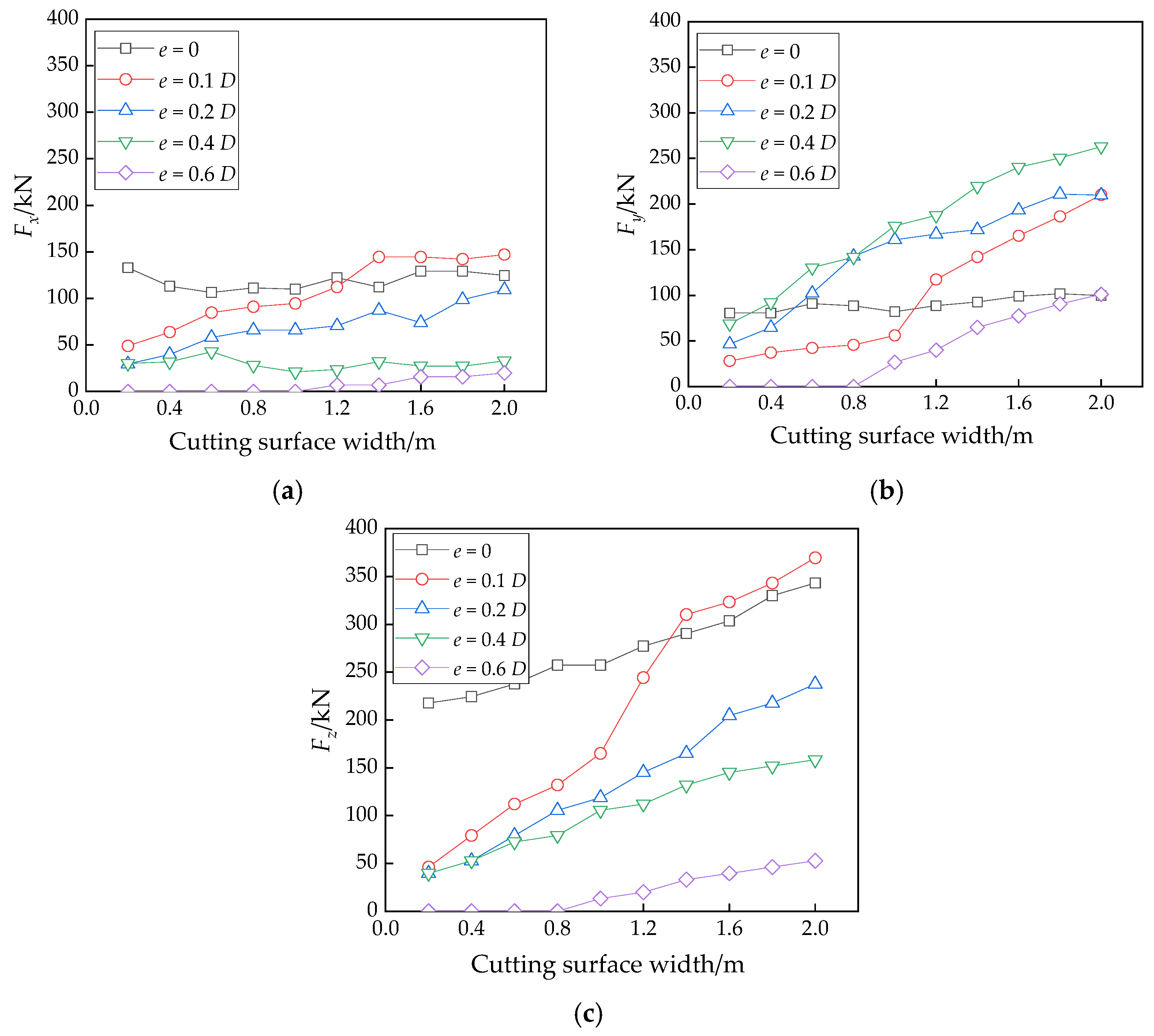
6.1. Effect of Cutting Surface Width
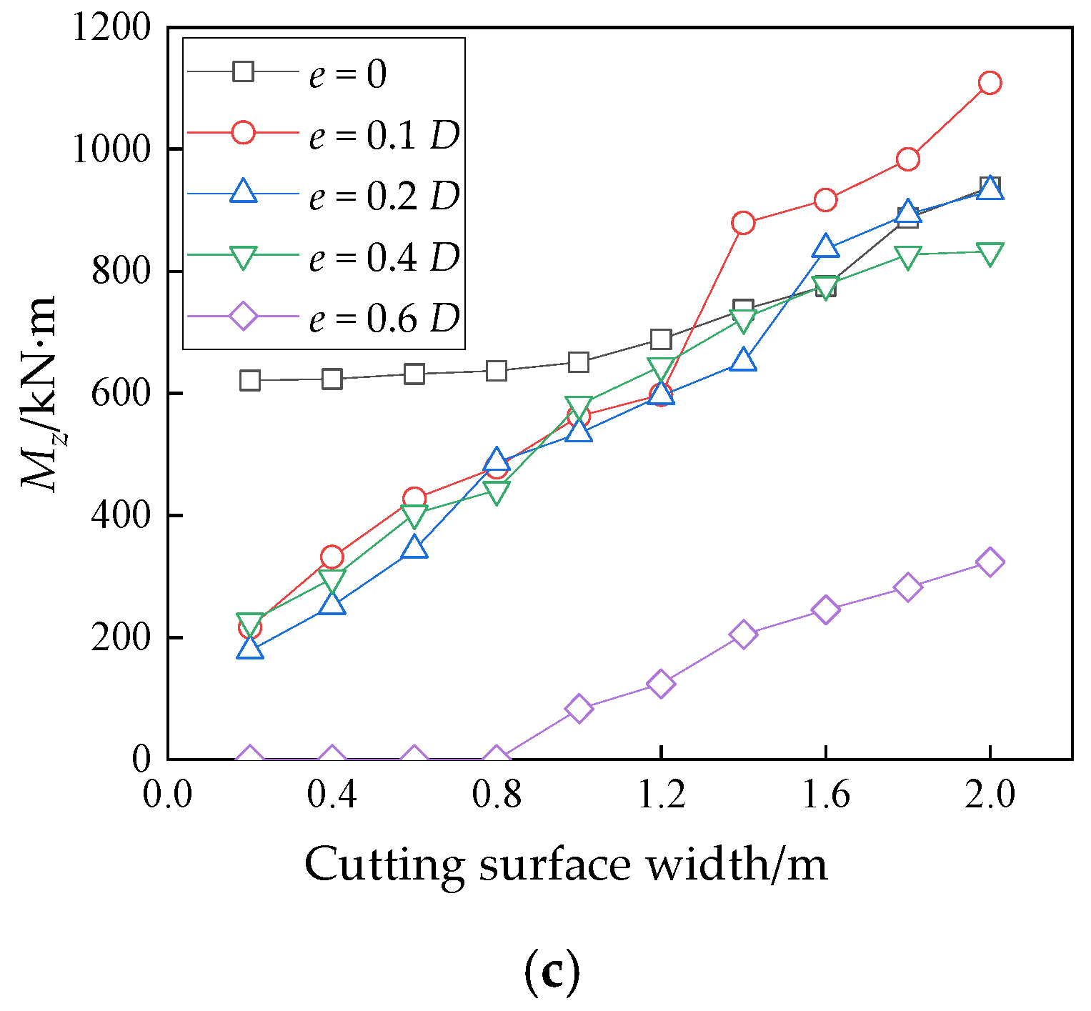
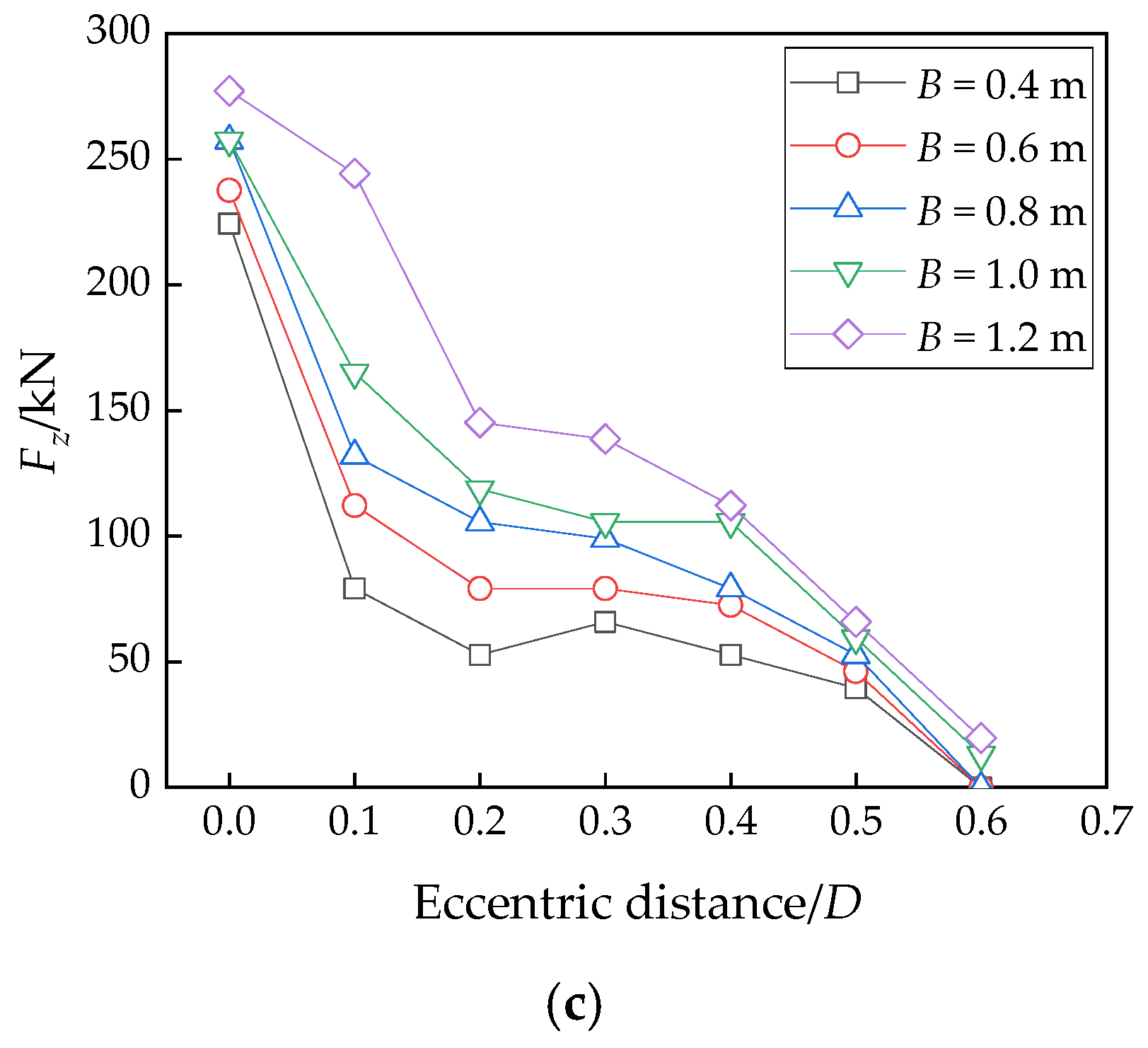
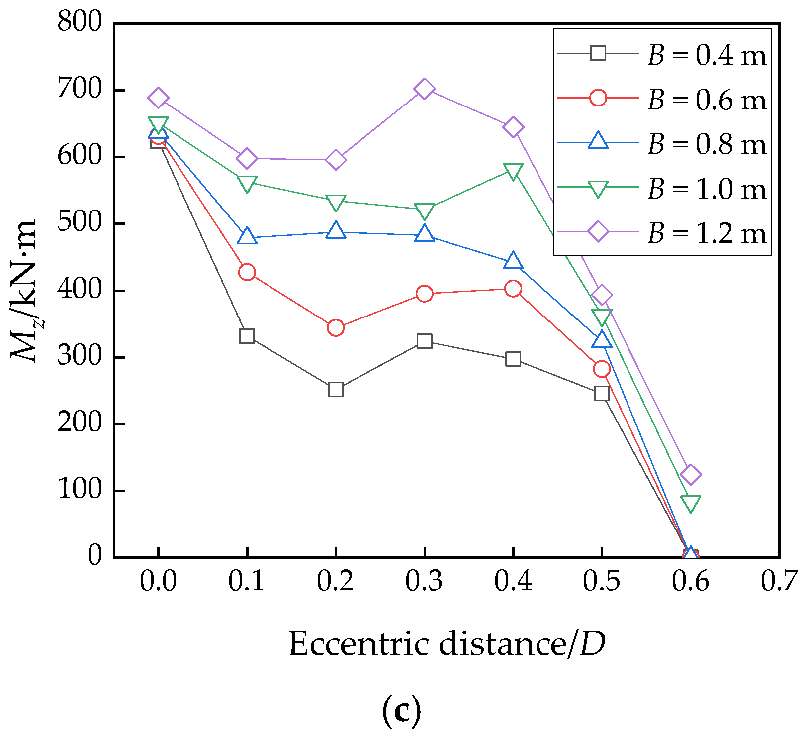
6.2. Effect of the Eccentric Distance
7. Conclusions
- (1)
- The calculation and field test results show that when the shield machine cuts reinforced concrete piles, there is a significant interaction between the cutter head and the piles, which causes obvious changes in the shield operation parameters and shield performance.
- (2)
- The number of tools has a significant effect on the additional torque of cutter head. The additional torque fluctuates with the rotation of cutter head and increases obviously with the increase of the number of tools that are inside the cutting area. The number of these tools are also determined by the arrangement of tools, cutting surface width and eccentric distance.
- (3)
- As the cutting distance increases, the additional torque of cutter head shows a trend of first increasing and then decreasing and reaches the maximum value when the cutting distance reaches the radius of pile. The maximum additional torque from the field test in this paper is about 1000 kN·m. This suggests that it is important to pay close attention to the torque and ensure that there is sufficient torque reserve.
- (4)
- The interaction force under different cutting surface width and eccentric distance conditions are given and discussed. The penetration force in the shield tunneling direction is usually greater than the unbalanced force in the other two directions. The additional torque of cutter head rotation is usually greater than the unbalanced moments in the other two directions as well. Besides, the additional force and additional moment of the cutter head increase with the increase of the cutting surface width. The impacts of eccentric distance on additional force and additional moment are complicated.
- (5)
- The additional force and additional moment given in this paper can provide reference for similar engineering. The discussion of the interaction between piles and cutter head under the conditions of different cutting surface width and different eccentric distances can provide guidance for the setting of shield operation parameters in other field projects with similar tools configurations and cutting conditions. However, the data given in this article are based on specific examples of project. The specific calculation and analysis of actual engineering conditions should be considered when findings of this study are applied to different projects.
Author Contributions
Funding
Institutional Review Board Statement
Informed Consent Statement
Data Availability Statement
Acknowledgments
Conflicts of Interest
References
- Liao, S.; Liu, J.; Wang, R.; Li, Z. Shield tunneling and environment protection in Shanghai soft ground. Tunn. Undergr. Space Technol. 2009, 24, 454–465. [Google Scholar] [CrossRef]
- Su, J.; Fang, Q.; Zhang, D.; Niu, X.; Liu, X.; Jie, Y. Bridge responses induced by adjacent subway station construction using shallow tunneling method. Adv. Civ. Eng. 2018, 2018, 8918749. [Google Scholar] [CrossRef]
- Koyama, Y. Present status and technology of shield tunneling method in Japan. Tunn. Undergr. Space Technol. 2003, 18, 145–159. [Google Scholar] [CrossRef]
- Zhang, C.; Zhao, Y.; Zhang, Z.; Zhu, B. Case Study of Underground Shield Tunnels in Interchange Piles Foundation Underpinning Construction. Appl. Sci. 2021, 11, 1611. [Google Scholar] [CrossRef]
- Li, Z.; Chen, Z.; Wang, L.; Zeng, Z.; Gu, D. Numerical simulation and analysis of the pile underpinning technology used in shield tunnel crossings on bridge pile foundations. Undergr. Space 2021, 6, 396–408. [Google Scholar] [CrossRef]
- Zhang, L. Study on underpinning scheme of viaduct pile foundation crossed by shield tunnel. IOP Conf. Ser. Earth Environ. Sci. 2020, 570, 052028. [Google Scholar] [CrossRef]
- Selemetas, D.; Standing, J.; Zdravković, L. Response of full-scale piles to EPBM tunnelling in London Clay. Géotechnique 2017, 67, 823–836. [Google Scholar] [CrossRef]
- Iwasaki, Y.; Watanabe, H.; Fukuda, M.; Hirata, A.; Hori, Y. Construction control for underpinning piles and their behaviour. Geotechnique 1994, 44, 681–689. [Google Scholar] [CrossRef]
- Wang, Y.; Wang, X.; Xiong, Y.; Yang, Z.; Zhang, J. Full-Scale Laboratory Test of Cutting Large-Diameter Piles Directly by Shield Cutterhead. Adv. Civ. Eng. 2022, 12, 1–11. [Google Scholar] [CrossRef]
- Xu, Q.; Zhu, H.; Ma, X.; Ma, Z.; Li, X.; Tang, Z.; Zhuo, Z. A case history of shield tunnel crossing through group pile foundation of a road bridge with pile underpinning technologies in Shanghai. Tunn. Undergr. Space Technol. 2015, 45, 20–33. [Google Scholar] [CrossRef]
- Chen, L.; Poulos, H.; Loganathan, N. Pile responses caused by tunneling. J. Geotech. Geoenviron. 1999, 125, 207. [Google Scholar] [CrossRef]
- Huang, M.; Zhang, C.; Li, Z. A simplified analysis method for the influence of tunneling on grouped piles. Tunn. Undergr. Space Technol. 2009, 24, 410–422. [Google Scholar] [CrossRef]
- Xiang, Y.; Feng, S. Theoretical prediction of the potential plastic zone of shallow tunneling in vicinity of pile foundation in soils. Tunn. Undergr. Space Technol. 2013, 38, 115–121. [Google Scholar] [CrossRef]
- Marshall, A. Tunnel-Pile Interaction Analysis Using Cavity Expansion Methods. J. Geotech. Geoenviron. 2012, 138, 1237–1246. [Google Scholar] [CrossRef]
- Marshall, A.; Haji, T. An analytical study of tunnel–pile interaction. Tunn. Undergr. Space Technol. 2015, 45, 43–51. [Google Scholar] [CrossRef]
- Franza, A.; Marshall, A.; Haji, T.; Abdelatif, A.; Carbonari, S.; Morici, M. A simplified elastic analysis of tunnel-piled structure interaction. Tunn. Undergr. Space Technol. 2017, 61, 104–121. [Google Scholar] [CrossRef]
- Zhang, Z.; Huang, M.; Xu, C.; Jiang, Y.; Wang, W. Simplified solution for tunnel-soil-pile interaction in Pasternak’s foundation model. Tunn. Undergr. Space Technol. 2018, 78, 146–158. [Google Scholar] [CrossRef]
- Afifipour, M.; Sharifzadeh, M.; Shahriar, K.; Jamshidi, H. Interaction of twin tunnels and shallow foundation at Zand underpass, Shiraz metro, Iran. Tunn. Undergr. Space Technol. 2011, 26, 356–363. [Google Scholar] [CrossRef]
- Jongpradist, P.; Kaewsri, T.; Sawatparnich, A.; Suwansawat, S.; Youwai, S.; Kongkitkul, W.; Sunitsakul, J. Development of tunneling influence zones for adjacent pile foundations by numerical analyses. Tunn. Undergr. Space Technol. 2013, 34, 96–109. [Google Scholar] [CrossRef]
- Hong, Y.; Soomro, M.; Ng, C.W. Settlement and load transfer mechanism of pile group due to side-by-side twin tunnelling. Comput. Geotech. 2015, 64, 105–119. [Google Scholar] [CrossRef]
- Li, Y.; Zhang, W. Investigation on passive pile responses subject to adjacent tunnelling in anisotropic clay. Comput. Geotech. 2020, 127, 103782. [Google Scholar] [CrossRef]
- Fu, J.; Yang, J.; Zhu, S.; Shi, Y. Performance of Jet-Grouted Partition Walls in Mitigating the Effects of Shield-Tunnel Construction on Adjacent Piled Structures. J. Perform. Constr. Fac. 2017, 31, 04016096. [Google Scholar] [CrossRef]
- Kong, S.; Oh, D.; Lee, S.; Kim, C.; Lee, Y. Effects of Pile Installation on Existing Tunnels Using Model Test and Numerical Analysis with Medium Density Sand. Appl. Sci. 2021, 11, 6904. [Google Scholar] [CrossRef]
- Loganathan, N.; Poulos, H.; Stewart, D. Centrifuge model testing of tunnelling-induced ground and pile deformations. Géotechnique 2000, 50, 283–294. [Google Scholar] [CrossRef]
- Jacobsz, S.; Standing, J.; Mair, R.; Hagiwara, T.; Sugiyama, T. Centrifuge modelling of tunnelling near driven piles. Soils Found. 2004, 44, 49–56. [Google Scholar] [CrossRef]
- Chiang, K.; Lee, C. Responses of single piles to tunneling-induced soil movements in sandy ground. Can. Geotech. J. 2007, 44, 1224–1241. [Google Scholar] [CrossRef]
- Marshall, A.; Robert, J. Tunneling beneath driven or jacked end-bearing piles in sand. Can. Geotech. J. 2011, 48, 1757–1771. [Google Scholar] [CrossRef]
- Ng, C.; Hu, L.; Peng, S. Three-dimensional centrifuge modelling of the effects of twin tunnelling on an existing pile. Tunn. Undergr. Space Technol. 2013, 35, 189–199. [Google Scholar] [CrossRef]
- Ng, C.; Mukhtiar, A.; Yi, H. Three-dimensional centrifuge modelling of pile group responses to side-by-side twin tunnelling. Tunn. Undergr. Space Technol. 2014, 43, 350–361. [Google Scholar] [CrossRef]
- Franza, A.; Marshall, A. Centrifuge modeling study of the response of piled structures to tunneling. J. Geotech. Geoenviron. 2018, 144, 04017109. [Google Scholar] [CrossRef]
- Lee, Y.; Richard, H. Influence zones for 2D pile–soil-tunnelling interaction based on model test and numerical analysis. Tunn. Undergr. Space Technol. 2007, 22, 325–342. [Google Scholar] [CrossRef]
- Meguid, M.; Joe, M. Investigation of tunnel-soil-pile interaction in cohesive soils. J. Geotech. Geoenviron. 2009, 135, 973–979. [Google Scholar] [CrossRef]
- Deng, L.; Yuan, Y.; Zhuang, Q.; Li, X.; Zhang, C.; Li, W. Novel PDC cutter for reinforced concrete based on linear and rotational cutting tests. Tunn. Undergr. Space Technol. 2022, 129, 104681. [Google Scholar] [CrossRef]
- Yuan, D.; Wang, F.; Dong, C.; Han, B.; Wang, M. Study on new-style cutter for shield cutting large-diameter reinforced concrete pile. China J. Highw. Transp. 2016, 29, 89. (In Chinese) [Google Scholar] [CrossRef]
- Wang, F.; Yuan, D.; Dong, C.; Han, B.; Nan, H.; Wang, M. Study on cutter configuration for directly shield cutting of large-diameter piles. China Civ. Eng. J. 2013, 46, 127–135. (In Chinese) [Google Scholar] [CrossRef]
- Copur, H.; Bilgin, N.; Balci, C.; Tumac, D.; Avunduk, E. Effects of Different Cutting Patterns and Experimental Conditions on the Performance of a Conical Drag Tool. Rock Mech. Rock Eng. 2017, 5, 1585–1609. [Google Scholar] [CrossRef]
- Banadaki, M.; Mohanty, B. Numerical simulation of stress wave induced fractures in rock. Int. J. Impact Eng. 2012, 40, 16–25. [Google Scholar] [CrossRef]
- Xu, Y.; Li, X.; Yang, Y.; Mu, J.; Su, W. Dynamic response test of shield cutter in the process of cutting concrete. J. Harbin Inst. Technol. 2021, 53, 182–189. (In Chinese) [Google Scholar] [CrossRef]
- Xu, P.; Zuo, S. Study on the JH-2 Model Parameters for Metro Shield Cutting Reinforced Concrete Pile. Geotech. Geol. Eng. 2021, 39, 5267–5278. [Google Scholar] [CrossRef]
- Su, W.; Li, X.; Xu, Y.; Jin, D. Numerical simulation of shield tool cutting concrete based on HJC model. J. ZheJiang Univ. Eng. Sci. 2020, 54, 1106–1114. (In Chinese) [Google Scholar] [CrossRef]


| Layer | Thickness (m) | Density ρ (g/cm3) | Cohesion c (kPa) | Friction Angle φ (°) |
|---|---|---|---|---|
| ①1 | 3.0 | - | - | - |
| ②3 | 5.6 | 1.98 | 0 | 28.5 |
| ⑦2 | 3.1 | 2.08 | 0 | 33.8 |
| ②4 | 4.0 | 1.93 | 28.9 | 20.6 |
| ⑦2 | 9.9 | 2.08 | 0 | 33.8 |
| ⑦1 | 4.2 | 1.94 | 32.5 | 19.9 |
| ⑦2 | 12.3 | 2.08 | 0 | 33.8 |
| Strength Parameters | Damage Parameters | |||||
| A | B | N | SFMAX | D1 | D2 | EFMIN |
| 0.27 | 1.5 | 0.87 | 20 | 0.04 | 1.0 | 0.01 |
| Equation of State Parameters | ||||||
| p1 (GPa) | pc (GPa) | μ1 | μc | K1 (GPa) | K2 (GPa) | K3 (GPa) |
| 1.780 | 0.008 | 0.16 | 7 × 10⁻⁴ | 9.23 | 141.24 | 136.50 |
| Basic Parameters | Strain Rate | |||||
| ρ (kg/m3) | G (MPa) | T (MPa) | fc (MPa) | C | ||
| 2110 | 8750 | 1.62 | 24.45 | 0.012 | ||
| Stage | Distance (mm) | Advance Rate (mm/min) | Rotation Rate (rpm) | Rotation Direction | Thrust (kN) | ||
|---|---|---|---|---|---|---|---|
| Maximum | Average | Maximum | Average | ||||
| 1 | 150 | 8 | 1.88 | 0.8 | counter-clockwise | 1140 | 997.0 |
| 2 | 150 | 8 | 3.44 | 0.5, 0.8, 1.0 | counter-clockwise | 1450 | 1220.5 |
| 3 | 180 | 7 | 1.29 | 0.5 | clockwise | 1590 | 1199.6 |
| 4 | 230 | 6 | 1.68 | 0.8 | clockwise | 1770 | 1446.8 |
| 5 | 300 | 8 | 3.11 | 0.8 | clockwise | 1760 | 1254.6 |
Disclaimer/Publisher’s Note: The statements, opinions and data contained in all publications are solely those of the individual author(s) and contributor(s) and not of MDPI and/or the editor(s). MDPI and/or the editor(s) disclaim responsibility for any injury to people or property resulting from any ideas, methods, instructions or products referred to in the content. |
© 2022 by the authors. Licensee MDPI, Basel, Switzerland. This article is an open access article distributed under the terms and conditions of the Creative Commons Attribution (CC BY) license (https://creativecommons.org/licenses/by/4.0/).
Share and Cite
Wang, X.; Yuan, D. Research on the Interaction between the Pile and Shield Machine in the Process of Cutting a Reinforced Concrete Pile Foundation. Appl. Sci. 2023, 13, 245. https://doi.org/10.3390/app13010245
Wang X, Yuan D. Research on the Interaction between the Pile and Shield Machine in the Process of Cutting a Reinforced Concrete Pile Foundation. Applied Sciences. 2023; 13(1):245. https://doi.org/10.3390/app13010245
Chicago/Turabian StyleWang, Xiaoyu, and Dajun Yuan. 2023. "Research on the Interaction between the Pile and Shield Machine in the Process of Cutting a Reinforced Concrete Pile Foundation" Applied Sciences 13, no. 1: 245. https://doi.org/10.3390/app13010245
APA StyleWang, X., & Yuan, D. (2023). Research on the Interaction between the Pile and Shield Machine in the Process of Cutting a Reinforced Concrete Pile Foundation. Applied Sciences, 13(1), 245. https://doi.org/10.3390/app13010245