1. Introduction
Milling is one of the most used technologies to achieve the final shape of mechanical components due to its flexibility and accuracy. Process productivity has been increased during the last decades by exploiting the advancements in tooling system, machine structure and numerical control (NC). The latter, in synergy with modern CAD/CAM software, allows for the implementation of advanced toolpath strategies [
1]. Traditionally, in 2.5-axis milling, two main strategies are used: direction-parallel and contour-parallel [
2]. In pocket milling, other approaches can be pursued, such as zig-zag milling, or component-offset pattern [
3]. All these strategies require algorithms to offset the final geometry to both compute the position of the center of the tool and, in case of multiple passes, to update the stock geometry. Several algorithms have been developed with the aim of improving efficiency and solve specific issues [
4,
5,
6,
7,
8]. Liu et al. [
4] obtained the offset curve by trimming and jointing the raw curve, resulting from just projecting the points of the polyline. A similar approach was proposed by Seong et al. [
5] that exploits distance maps to trim local and global self-intersections, which are the main sources of errors in offset computation. Omirou [
6] proposed to use a locus tracing concept for cutting radius offset and provides some applications to CNC machining. Choi and Park [
7] developed a method based on intersections of sculptured surfaces for offsetting point-sequence curves (PS- curves), while Wicklin computed offset regions by using circles at each vertex and rectangles along each edge [
8]. Contour offset can also be obtained by using a straight skeleton, but this could lead to sharp corners [
9]. Linear axis is an interesting alternative as a means to compute such offsets, reducing the sharp corners issue, as investigated by Palfrader and Held [
9]. However, all the presented techniques are dedicated to uniform offset of a polyline curve, characterized by a constant distance of each offset element (i.e., segments) from the initial contour elements.
Uniform offset is fundamental for most of the traditional toolpath approaches based on a geometric basis [
10]. Nevertheless, in the case of advanced CAM strategies increasingly adopted, the limitation of constant value offset, i.e., uniform machining/stock allowance, could be critical. Indeed, in some cases variable radial engagement of the tool during the toolpath could be preferred, leading to the need of a non-uniform stock allowance on the component that could be achieved only with a non-uniform offset algorithm, i.e., offset where the distance to the initial contour varies along that input. Generally, such an approach is required when the toolpaths are not only calculated on a geometric basis (i.e., considering only the removal of the material), but also involving technological aspects. For example, in thin-wall milling, if stiffness of the part is considered in selecting the optimal engagement, non-uniform machining allowance on the components could be desired. This is the case of the approach proposed by Wang et al. [
11] that developed a cutting sequence algorithm to reduce workpiece deformation, suggesting the use of different depths of cut during the cutting cycle, depending on the changing stiffness of the part. Starting from such a concept, Grossi et al. [
12] developed a method to compute the toolpath for milling thin-wall components. In their work, in each pass, the radial depth of cut changes continuously to achieve the desired quality without compromising productivity. To achieve this variable radial depth of cut, variable machining allowance on the component is required, and to implement such machining allowance on the final component a non-uniform offset algorithm is needed. Few works were dedicated to non-uniform offset, known also as variable-radius offset. Yan et al. [
13] proposed the so called “uneven offset” method, but the method is very specific and focuses on the elimination of materials remaining left on the corners. Qun and Rokne’s [
14] and Zhuo and Rossignac’s [
15] works are dedicated to the geometrical definition of the different offsets; however, they do not provide efficient and robust algorithms. Variable offset can be constructed based on sampling, using rendering-based methods [
16]; however, computational efficiency and accuracy in extracting the actual offset from the rendered images are still open issues. Recently, Held et al. [
17,
18] computed a variable offset exploiting the new variable-radius Voronoi diagrams. Although interesting, their works require several steps, increased effort in the implementation and are specific, since they do not apply to external offset.
This limitation is common to most of the proposed approaches for non-uniform offset that are designed on specific cases and they lack generality. This work presents a general algorithm for non-uniform offset of polyline curves, inspired by the uniform offset algorithm proposed by Wicklin [
8]. The method, based on 2D polygons and Boolean union operation, is robust for complexity of both the polyline and variable offset magnitude along that line. Indeed, the main contribution of the proposed approach is the generality: the algorithm can be applied to both external and internal offset and it is effective for any type of contour and variable offset desired, not returning ambiguities or intersections in the resulting contour. In addition, another novel aspect characterizing the proposed approach is its implementation: the method is not based on specific complex algorithms (e.g., rendering-based, straight skeleton or Voronoi diagrams), which generally not easy to implement, but only on simple basic steps, exploiting traditional operations (i.e., projections, Boolean operations). Such operations are already adopted in CAM software, but in the proposed approach they are adapted to be used to compute non-uniform offset and achieve a desired variable machining allowance on the part.
In
Section 2, the scope of the algorithm and the working principle is proposed, then in
Section 3 results on several examples and applications to thin-wall milling cases are shown. Finally, in
Section 4 some conclusions are drawn.
3. Results
In this section, the proposed algorithm is applied to different scenarios. First, different examples are provided to show how the algorithm could deal with complexity both in terms of initial contour and offset array. Then, two case studies are provided to show the potential application of the proposed approach.
3.1. Examples
In
Table 1 six examples are shown, in the first column the initial contour and the algorithm results are provided, while in the other two columns the polygon phase and the offset values applied are shown.
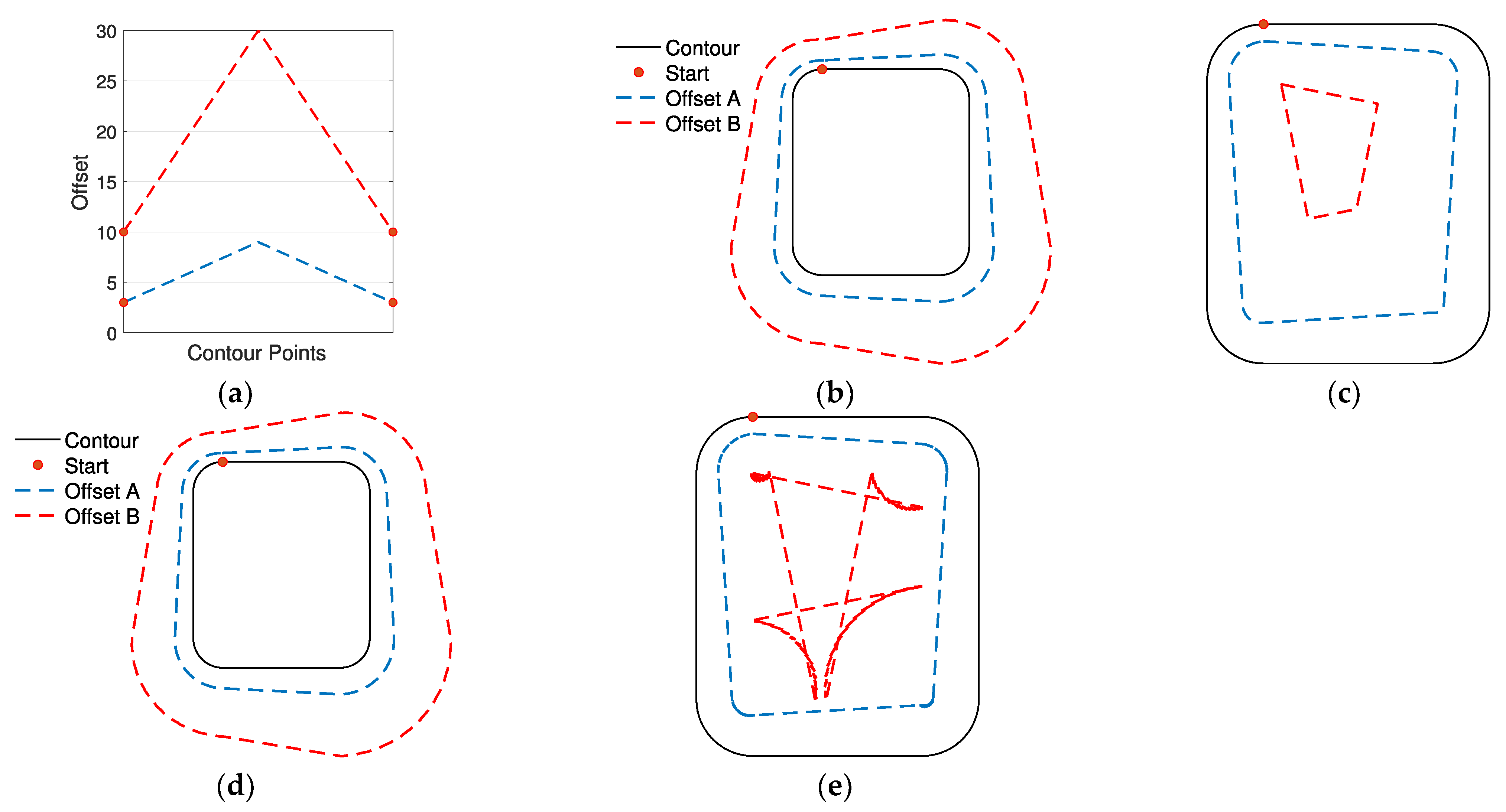
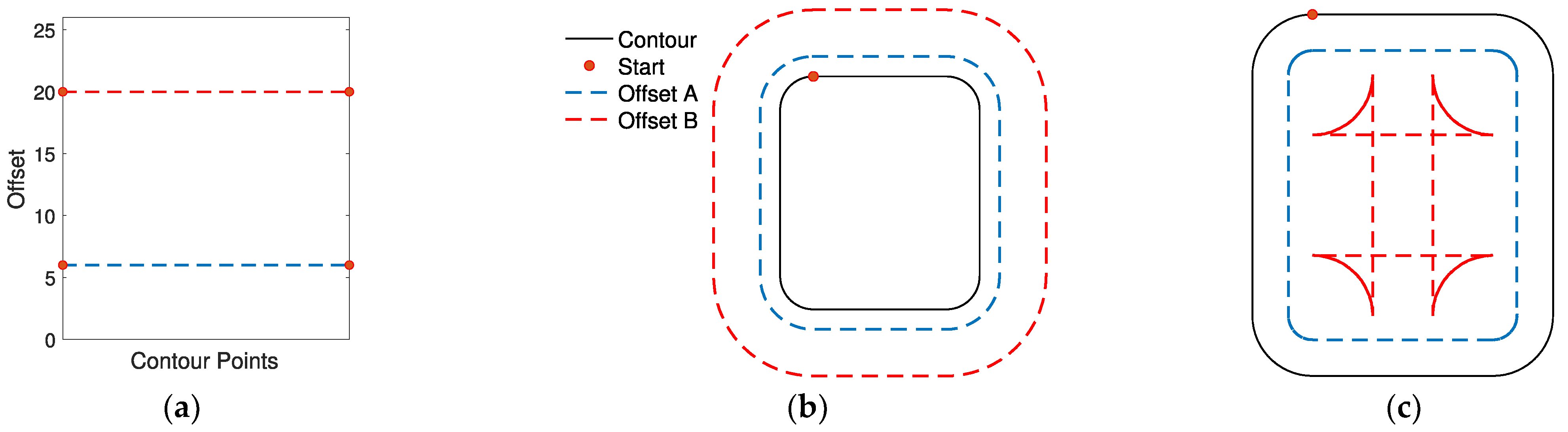
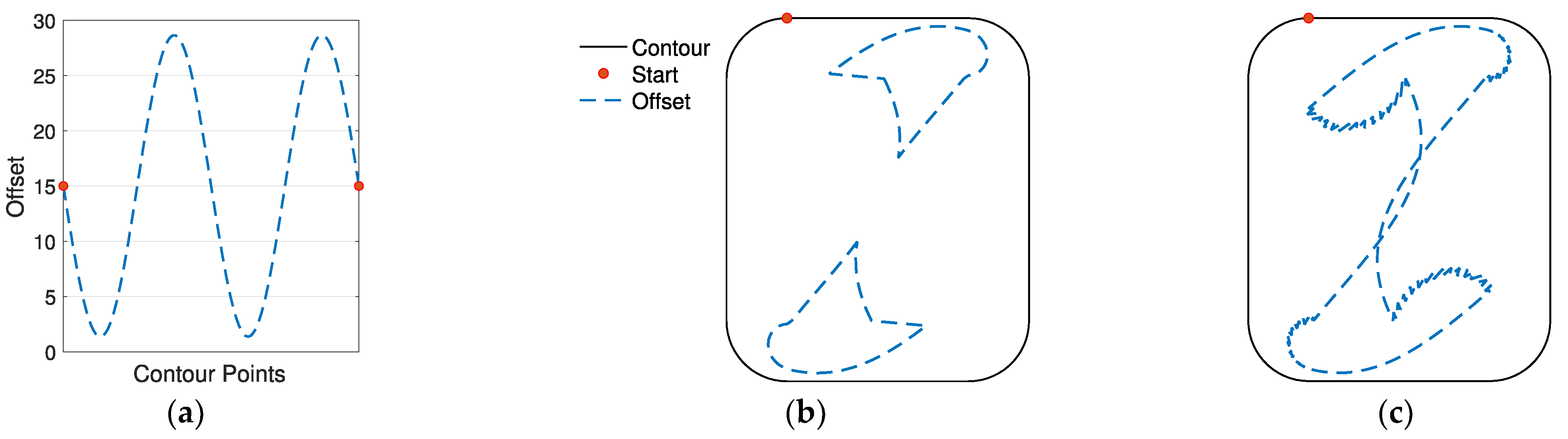
As is clear from the results, the proposed algorithm is able to handle both internal and external offset of complex initial contours and offset arrays. The first example shows how the algorithm works in an internal simple geometry with a triangle-shape offset array (same example in
Figure 1) and how self-intersection is intrinsically managed by the proposed approach. In the second, a sinusoidal offset array with high frequency is imposed to the same initial contour. The fluctuations generate a sinusoidal allowance on straight lines and asymmetrical intersections at the vertices, accurately represented by using the proposed algorithm. A sinusoidal offset array is provided to a more complex shape featuring convex and concave angles. Applying this offset externally (example 3) leads to variable thicknesses of the straight lines and edge rotation with different radii on the four convex vertices, while the intersection is computed in the concave angle. Example 4 shows the same complex shape with an internal sinusoidal offset and similar considerations can be drawn. The algorithm correctly computes both circular edge rotation at the convex vertex and the four intersections at the concave angles. In example 5, an offset array causing the creation of two different polylines is applied to the same initial contour of the previous two examples, while in example 6 an external offset to a curve (i.e., airfoil-shape) using a complex offset array is shown.
3.2. Application to Thin-Wall Components
In addition to the previous examples, which represent more theoretical applications rather than real case scenarios, more practical case studies are proposed.
Indeed, the proposed algorithm is dedicated to contouring operations in 2.5 axis milling considering a flat endmill as the cutter. In this context, the proposed algorithm starting from the polyline, which represents the finished part of the contour, produces the shape of the machining allowance to be left on the part based on the offset values assigned to each point of the starting polyline (i.e., semi-finished contour). These offset values identify the amount of allowance to be left on each point of the finished contour. Then, the actual toolpath could be obtained by applying an offset algorithm to the semi-finished contour previously obtained using the same offset value (i.e., endmill radius) for each point. Therefore, in 2.5 axis milling contouring operations, the proposed algorithm creates a toolpath able to achieve a variable radial depth of cut along the part contour. These conditions are particularly interesting in contouring operations in which both the tool and the workpiece are characterized by low stiffness. This type of operation is referred to as thin-wall milling, and it is a challenging topic in the manufacturing field. In detail, thin-wall components are increasingly adopted in modern industries for their favorable stiffness to weight ratio, but precision milling on these components is still a complicated task because unstable vibrations and large surface errors are inevitable during the process, limiting productivity. To ensure the required surface quality without compromising productivity, it is important to identify the potential of each portion of the thin-wall component in terms of stiffness so that the most profitable cutting parameters, which each portion can handle, are selected. In this regard, two applications for the definition of the semi-finished part in 2.5 milling are provided. It must be noted that, in the context of milling operations, the proposed method does not create the actual toolpath, but the desired semi-finished contour, which must be offset uniformly by the tool radius to obtain the effective toolpath. As already mentioned above as well as in the introduction, one potential application of the proposed algorithm is the definition of a variable machining allowance on the finished thin wall part to achieve a variable radial depth of cut during the finishing operation. Indeed, the possibility to adopt a different radial depth of cut during the finishing cycle allows for removal of more material on the stiffer zones, reducing the actual material removal only in the critical portions of the part. As shown in [
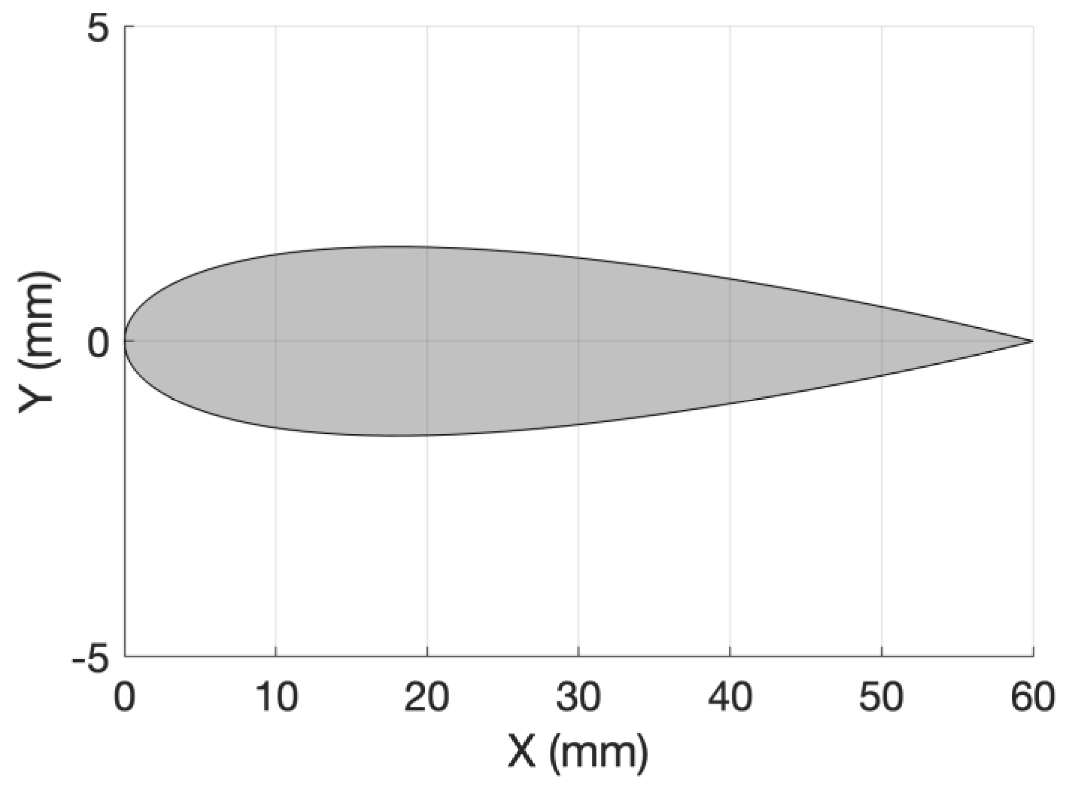
11], this allows an increase in productivity in comparison to the traditional constant engagement approach, in which the most conservative (i.e., minimum) radial depth of cut during the entire machining cycle must be used. Firstly, the proposed algorithm was applied to the case study proposed in [
12]: 2.5 milling of a NACA 0005 airfoil profile 60 mm long and 20 mm high (
Figure 6).
In the cited work, the authors aimed at identifying, from a static point of view, the highest value of the radial depth of cut in each portion of the airfoil so that the form error caused by the static deflection of the tool-workpiece couple does not fail the commanded tolerance. Workpiece deflection is predicted, including the effect of the material removal through finite elements methods. In detail, the method proposed by the authors starts by finding the stiffest portion of the airfoil. It evaluates the highest radial depth of cut possible within the imposed constraints, it updates accordingly the airfoil stiffness in the analyzed portion, and, following this practice, it continues analyzing the rest of the airfoil profile in reverse order with respect to the classic milling cycle. In this way the output of the method is the “desired” machining allowance to be left on the workpiece stock to obtain an airfoil which respects the commanded tolerance in each portion.
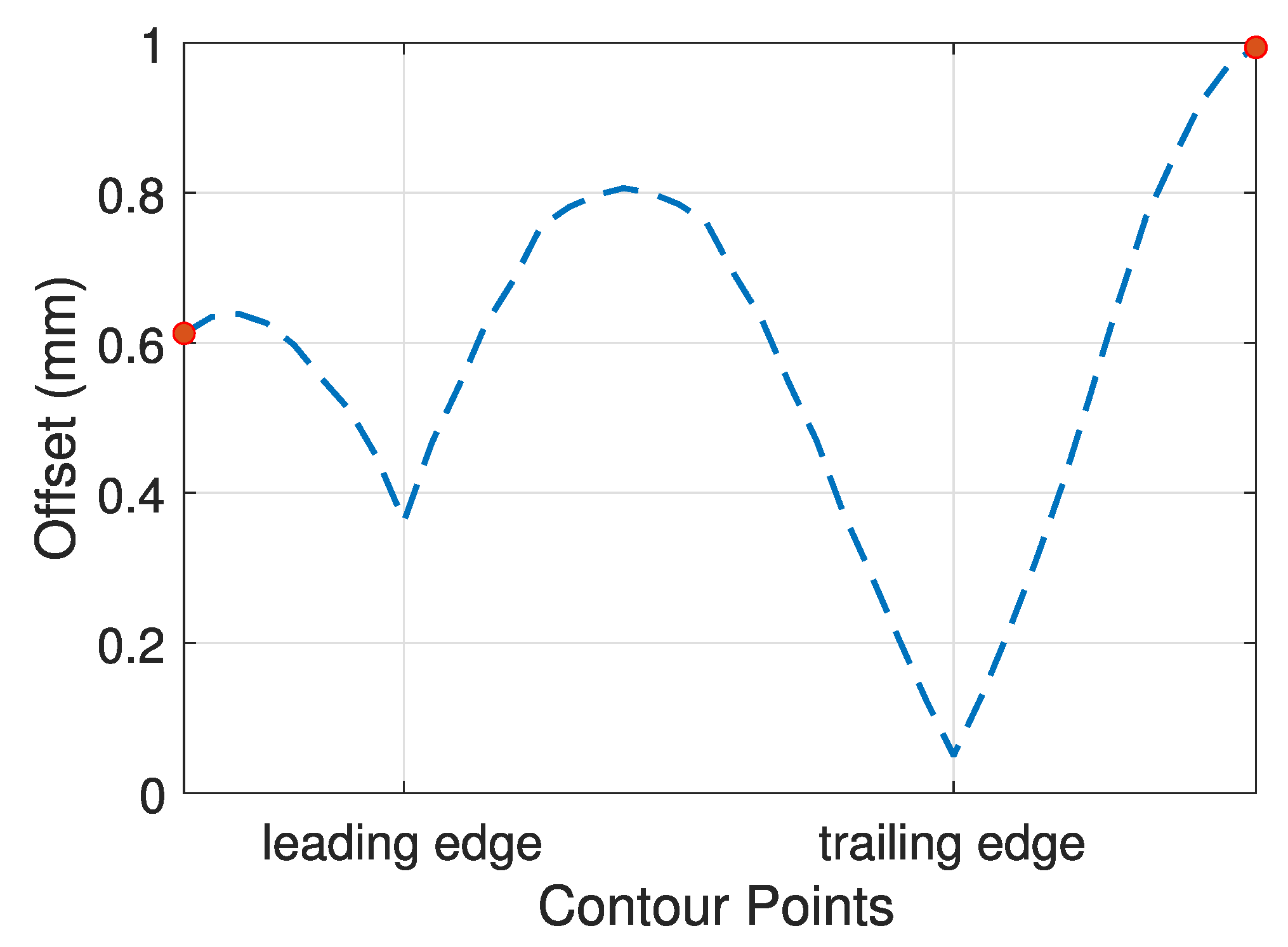
In the mentioned work, radial depth of cut was optimized to achieve a commanded tolerance (±0.02 mm) leading to a variable depth of cut. Indeed, since the blade presents significant differences in terms of local stiffness, in the thicker zones of the profile a higher depth of cut can be achieved, while in the critical points (e.g., trailing edge) a more conservative depth should be used. The resulting radial depth of cut is presented in
Figure 7. As expected, the figure shows the minimum radial depth of cut (i.e., offset of the contour) at the trailing edge, the most flexible portion of the blade. The starting point was set on the stiffest portion and discontinuity on this point is found between the beginning and the end of the cycle. This result is caused by the fact that during the operation, the thickness of the blade changes, affecting the stiffness and hence the allowable radial depth of cut. Please refer to [
12] for additional details on radial depth of cut computation.
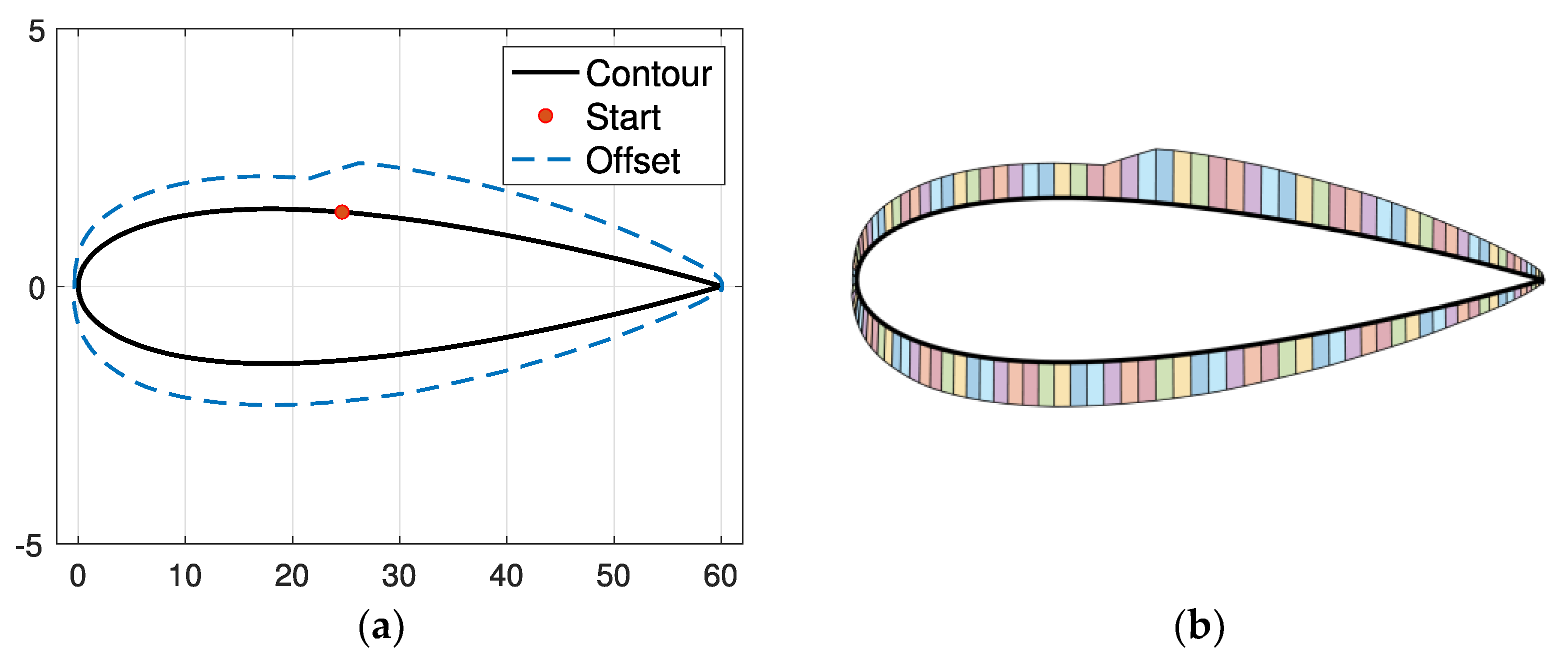
To achieve the desired radial depth of cut during the finishing operation, the semi-finished stock should be computed based on the initial contour adding the defined radial depth of cut as a machining allowance. This procedure was carried out using the proposed algorithm, and results are shown in
Figure 8. Results show that the proposed algorithm is able to perform the non-uniform offset of the blade contour, dealing with the discontinuity and returning the desired semi-finished profile.
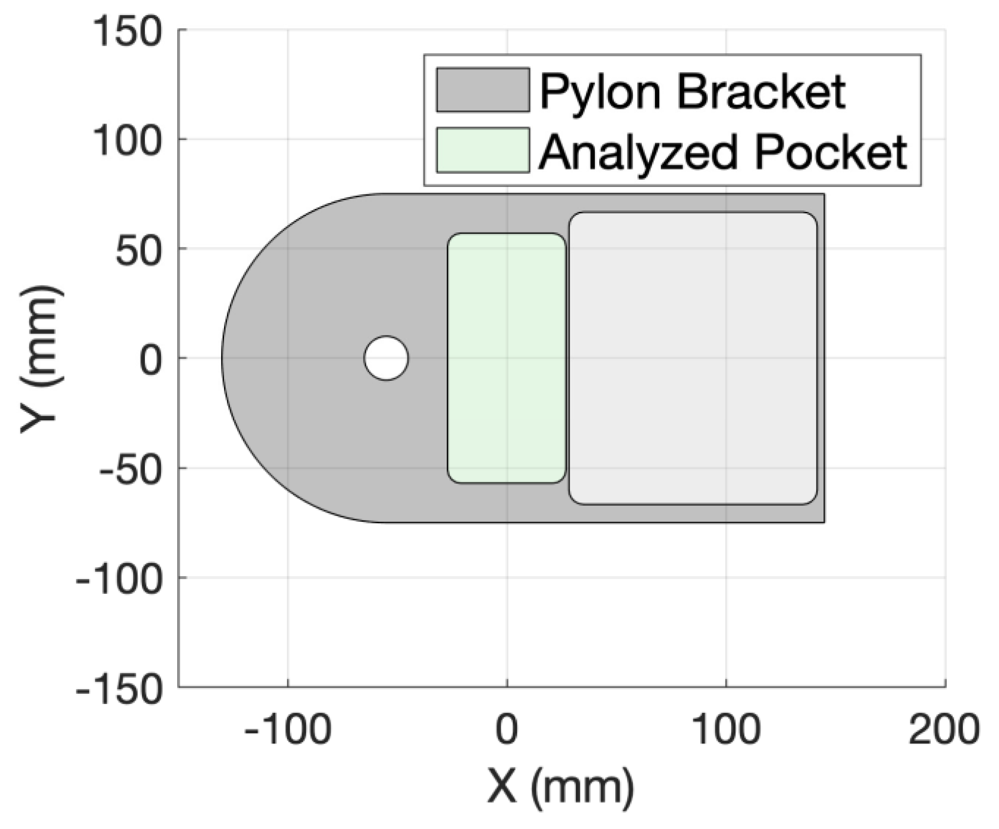
Since the blade application was dedicated to an external offset, generally easier to manage, an application to an internal offset in pocket 2.5 milling operations is also provided. The case study is a Pylon Bracket for aerospace application, such components often entail thin-wall structures and pocket milling. In our case, the pocket analyzed is the one in the middle, as highlighted in the 2D representation of
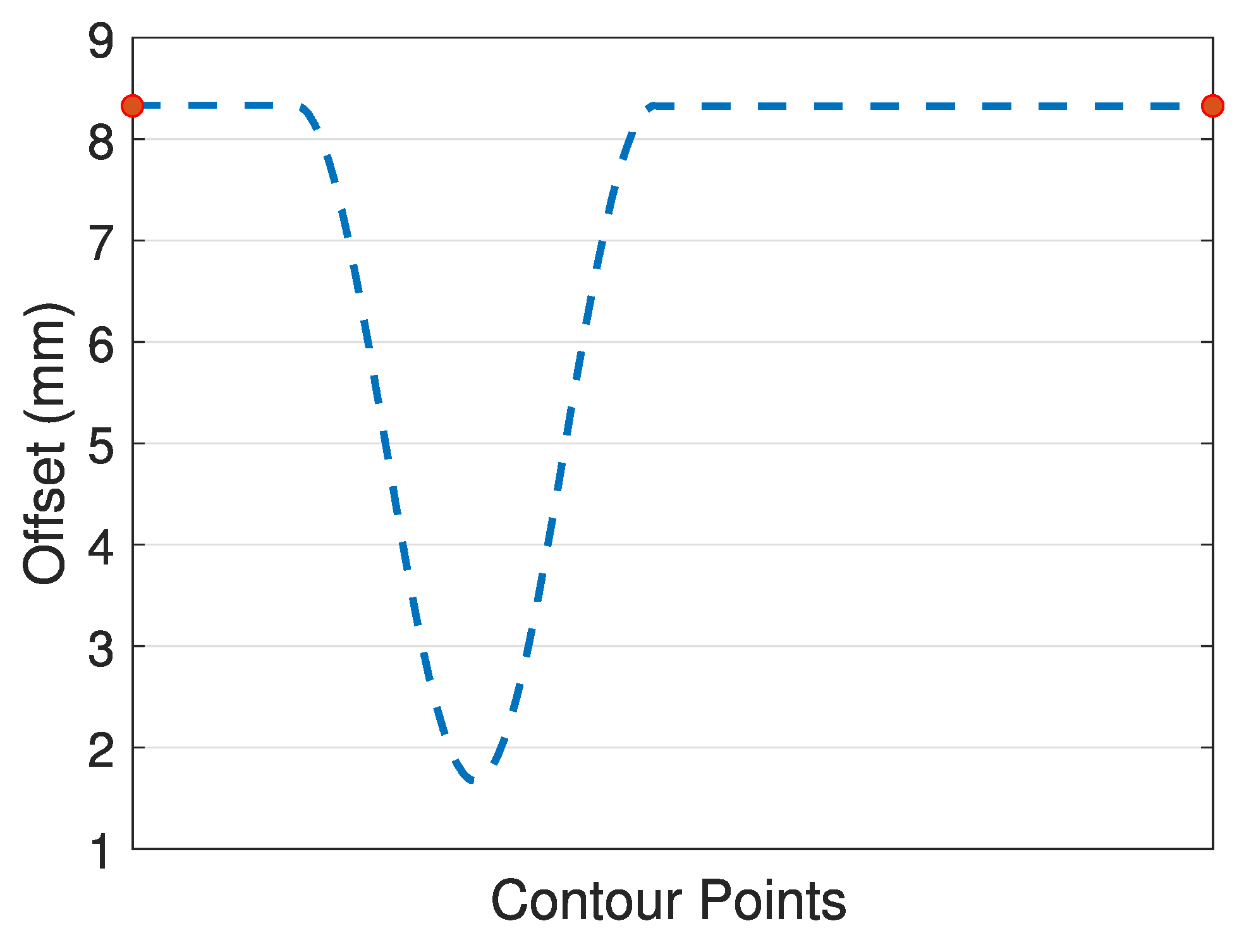
Figure 9. The 2.5 milling of the investigated pocket is not affected by the flexibility of the workpiece (thin-wall structure) for most of the operation, except for one of the sides that is characterized by a very thin wall (3 mm). Therefore, in this portion a variable radial depth of cut could be profitable: constant and standard radial depth of cut should be used in the thick portions, while drastically reduced radial depth of cut must be adopted in the thin-wall portion. An example of such possible depth of cut variation is provided in
Figure 10.
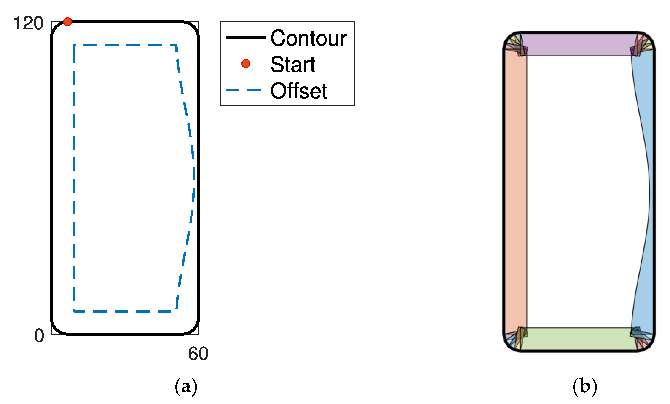
The desired radial depth of cut is applied through the developed offset algorithm to the initial contour to obtain the semi-finished pocket and results are shown in
Figure 11. The algorithm produces what is required: a constant offset in the thick portions and a reduced offset in the critical one. Milling the resulting offset contour to obtain the initial contour will entail a high radial depth of cut in all the regions, except for the thin zone where such depth of cut will be more conservative, as desired. As already mentioned, it is worth pointing out that since the offset polyline should be obtained by a milling operation, sharp edges cannot be achieved, and the real machining allowance will depend on the tool geometry (i.e., diameter) used for the roughing operation. This consideration is valid in general, the offset algorithm could result in sharp edge contours if such a contour represents the semi-finished component. As in the applications provided in this section, the diameter of the tool will affect the actual machined contour.
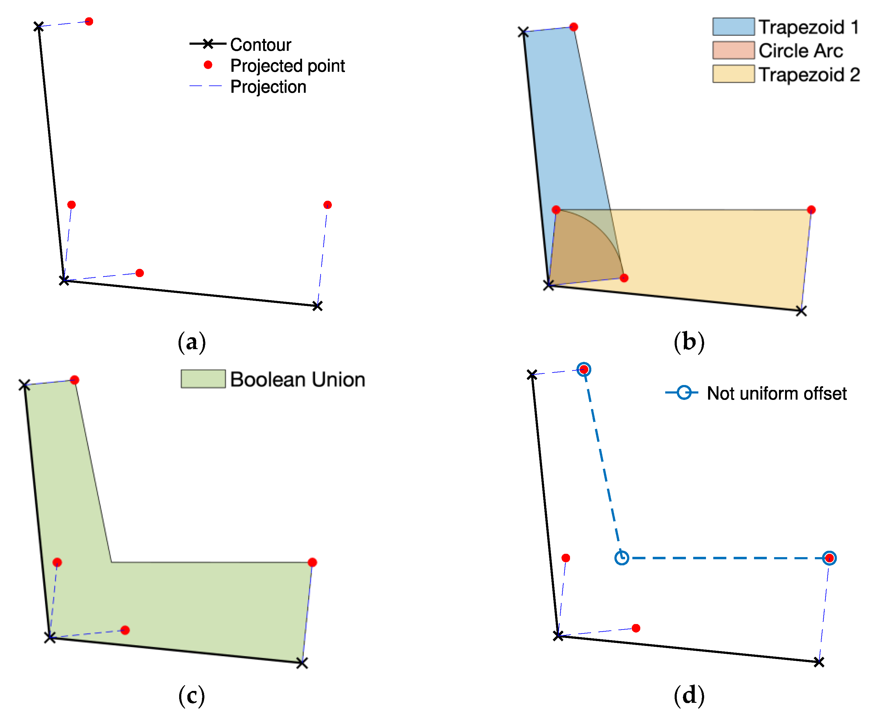
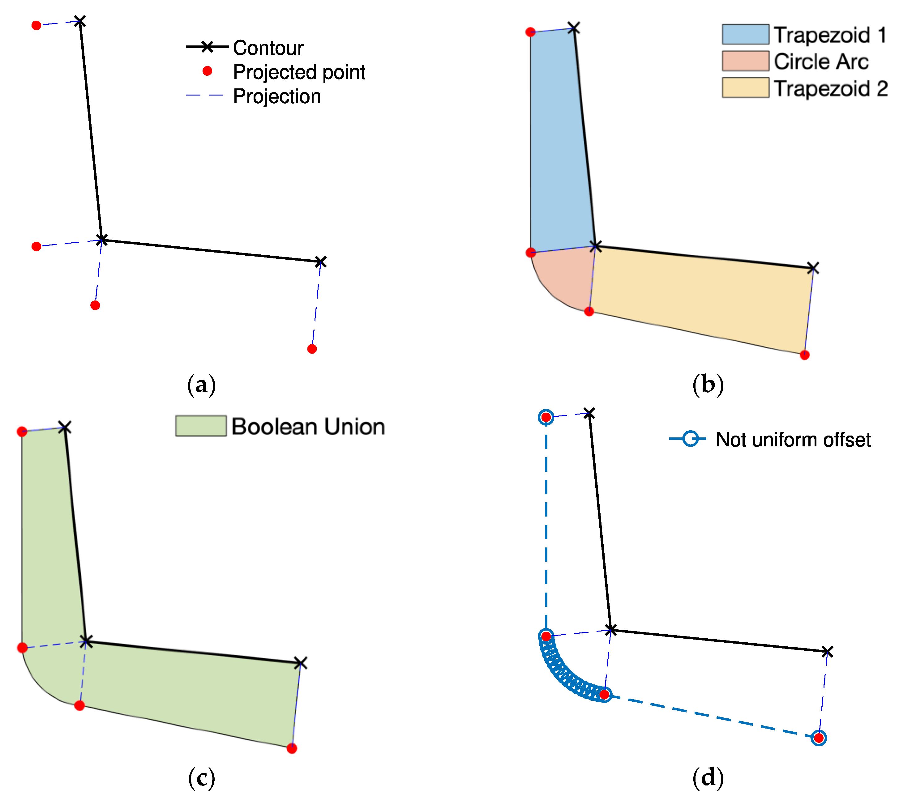
4. Discussion
In this work, a non-uniform offset (i.e., variable-radius offset) algorithm for CNC milling toolpath generation is proposed. This algorithm computes the non-uniform offset contour of a polyline both internally and externally. Basically, the proposed approach requires two inputs: (i) the initial contour, a closed 2D polyline curve and (ii) an offset array, including the offset values for each point. The method is based on Boolean union of 2D polygons and follows five simple steps: (i) projection segments of the initial contour are generated, (ii) a trapezoid for each initial segment is created, (iii) a circular sector is generated by rotating one projection segment on the other originating from the same point of the initial contour, (iv) Boolean union of all the polygons is performed, (v) boundary of interest (i.e., internal or external) is extracted. Results show the effectiveness of the proposed approach in several examples. In addition, the potential application to thin-wall 2.5 milling toolpath definition is shown using two different case studies: the external milling of a blade profile and the internal milling of a pylon bracket pocket. The efficiency of this algorithm needs further investigations requiring the implementation in a more suitable programming language (e.g., C++). Moreover, improvements to the implementation could be considered to increase the robustness of the approach. In addition, as a future development the algorithm applicability could be extended to be used in path planning, which is achieving a growing interest in the world of automation. This involves the generation of a route in presence of obstacles that must be avoided to achieve a collision-free operation of robots or entities moving in a certain scene. A promising tool widely used in this filed is the Minkowski sum algorithm, which is the point-wise sum of two sets [
19]. In motion planning, the first of the two sets could be the obstacle, while the second the end effector or, in general, moving entity. A similar result could be achieved with the algorithm proposed in the present paper where, point by point along the perimeter of the obstacle, the shape of the moving entity could be added to the one of the obstacles taking into account also the orientation of the moving entity itself, thus allowing for rotation. To achieve such a goal, further investigation and implementations of the proposed concept are needed.


