
A New Finite Element Analysis Model to Estimate Contact Stress in Ball Screw


Abstract
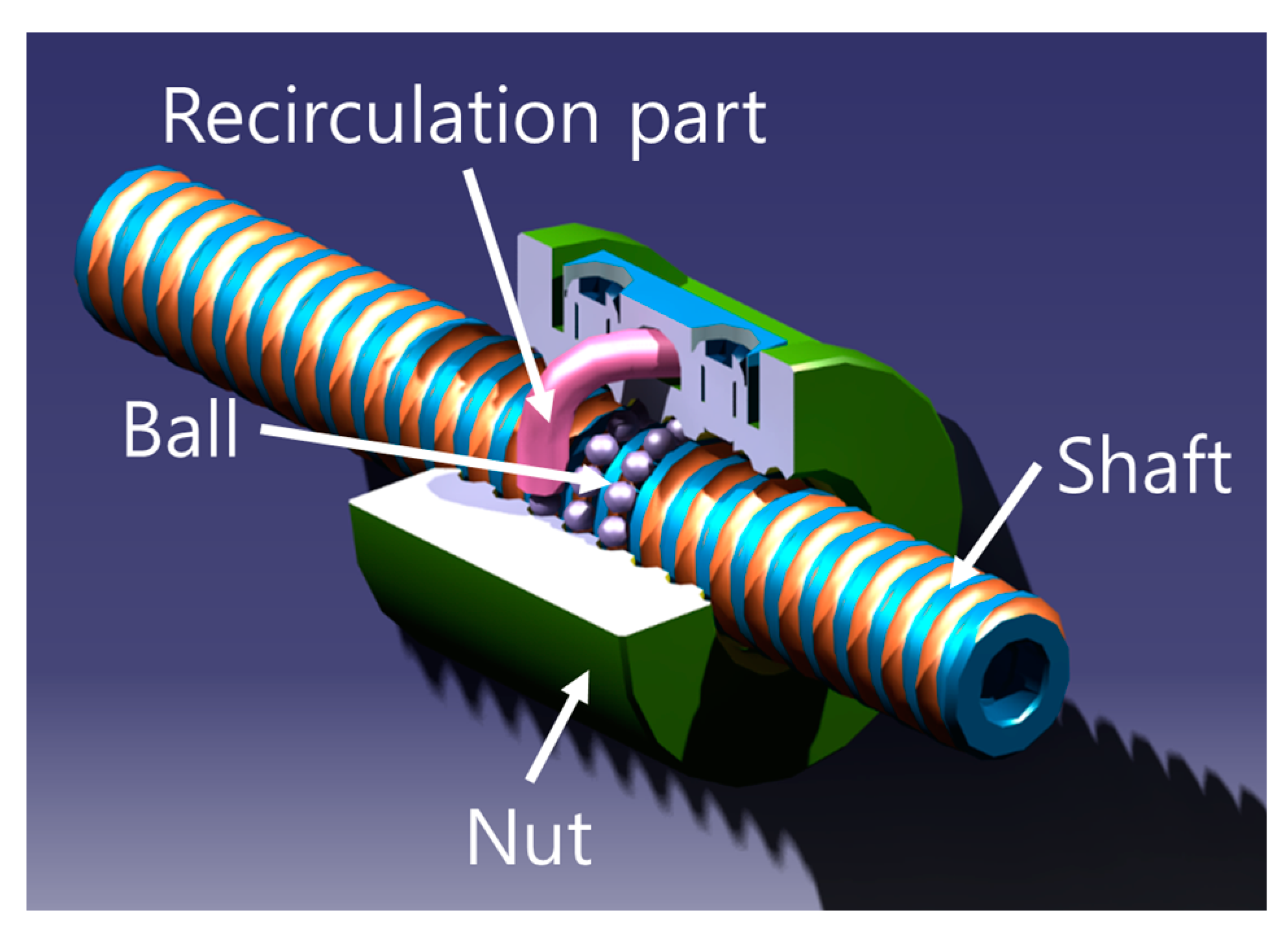
:1. Introduction
2. Theoretical Analysis
2.1. Assumptions
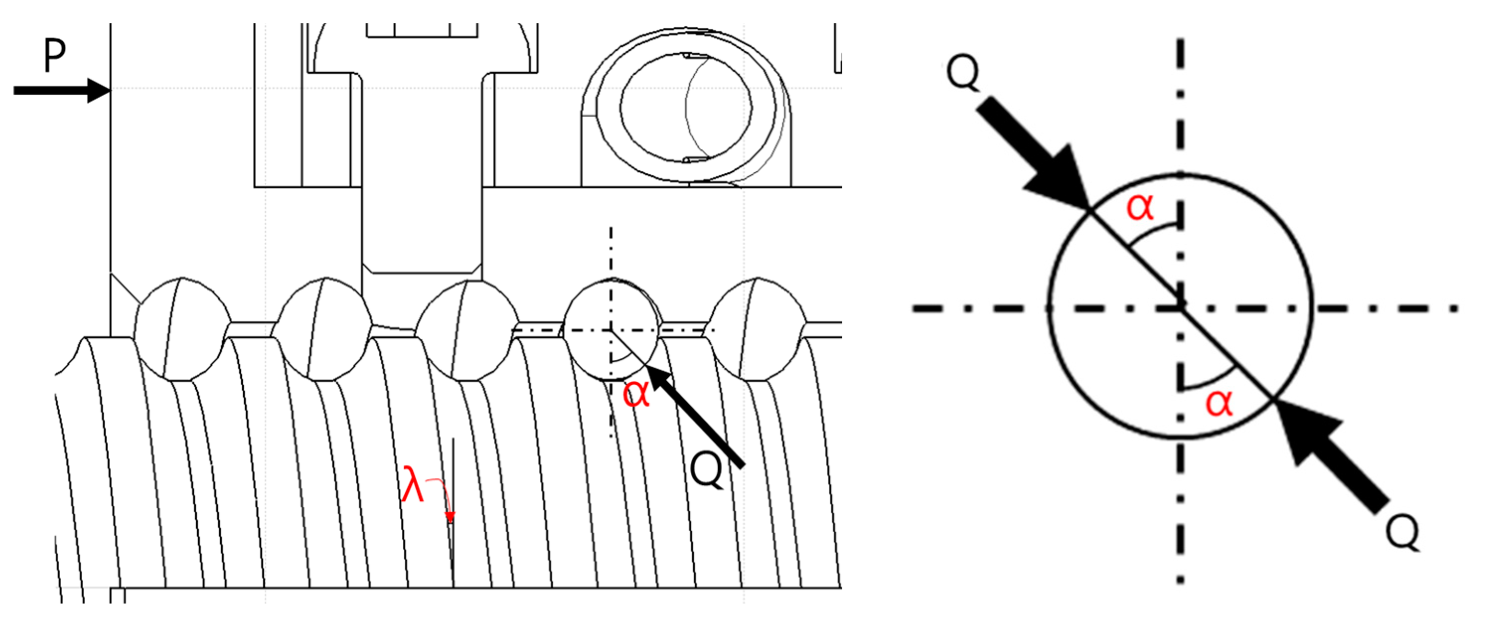
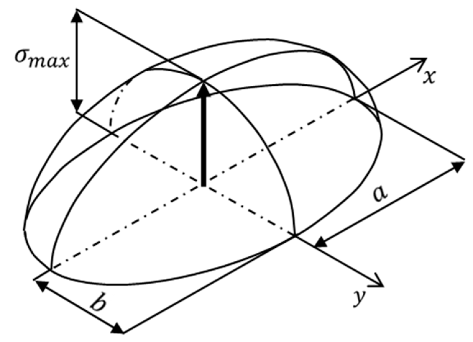
2.2. Theoretical Study of Ball Screw
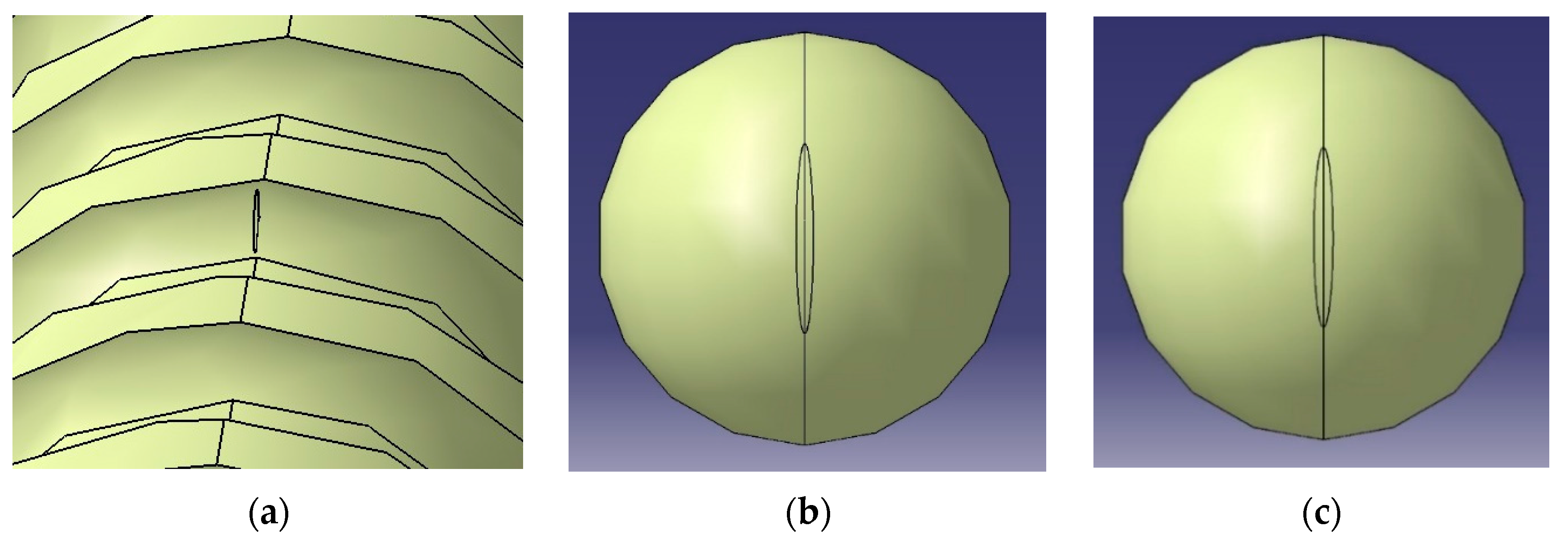
3. FEA
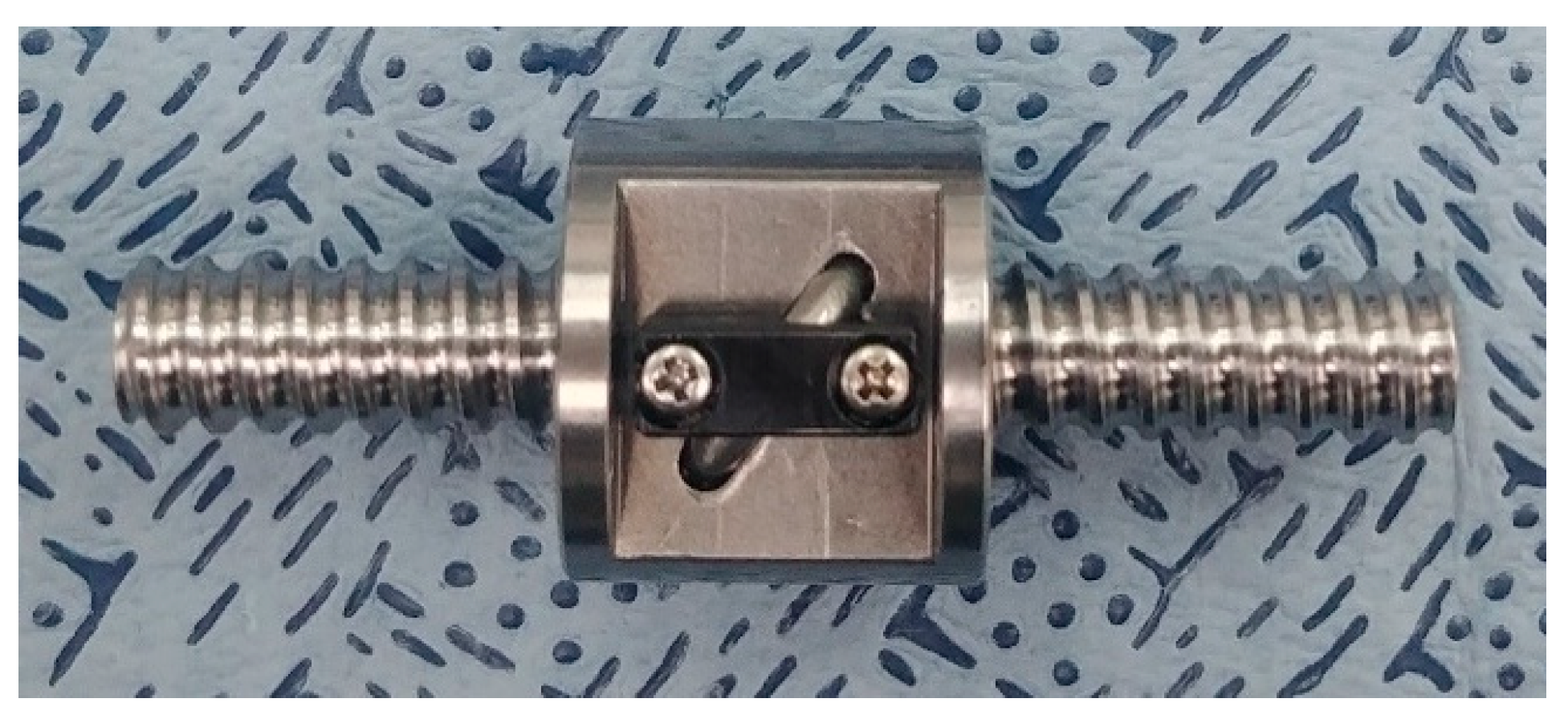
3.1. Subject Configuration and Material Property
3.2. Boundary Conditions
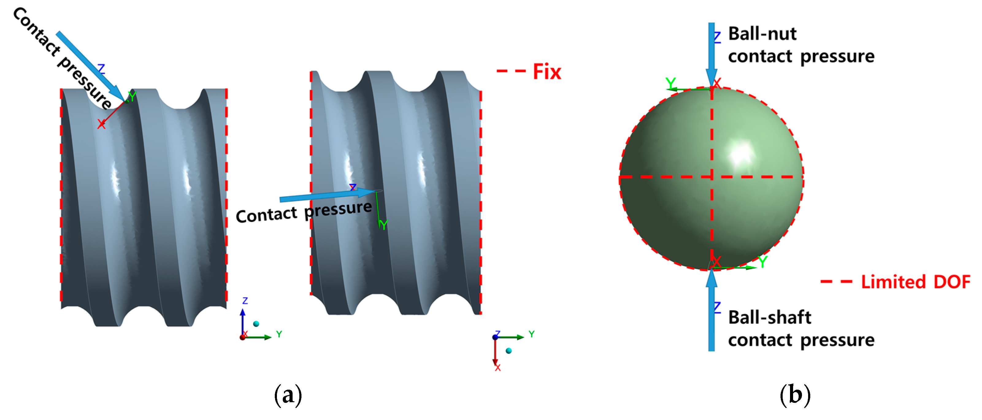
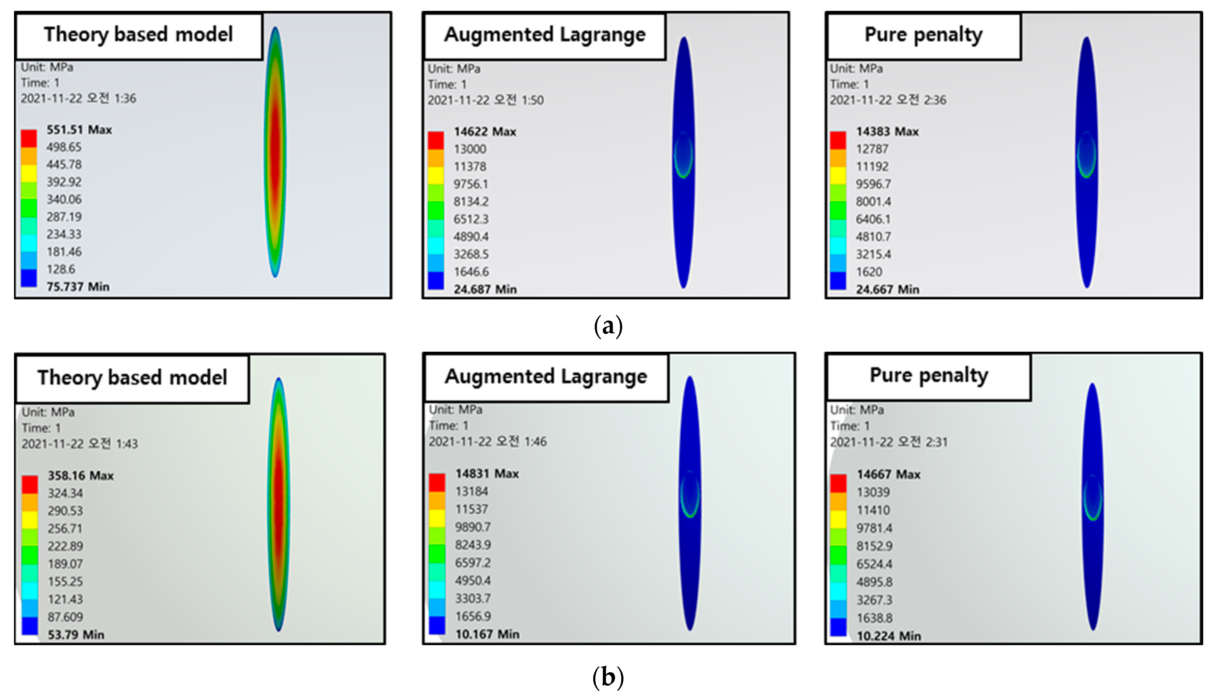
3.2.1. Contact Theory Based Model
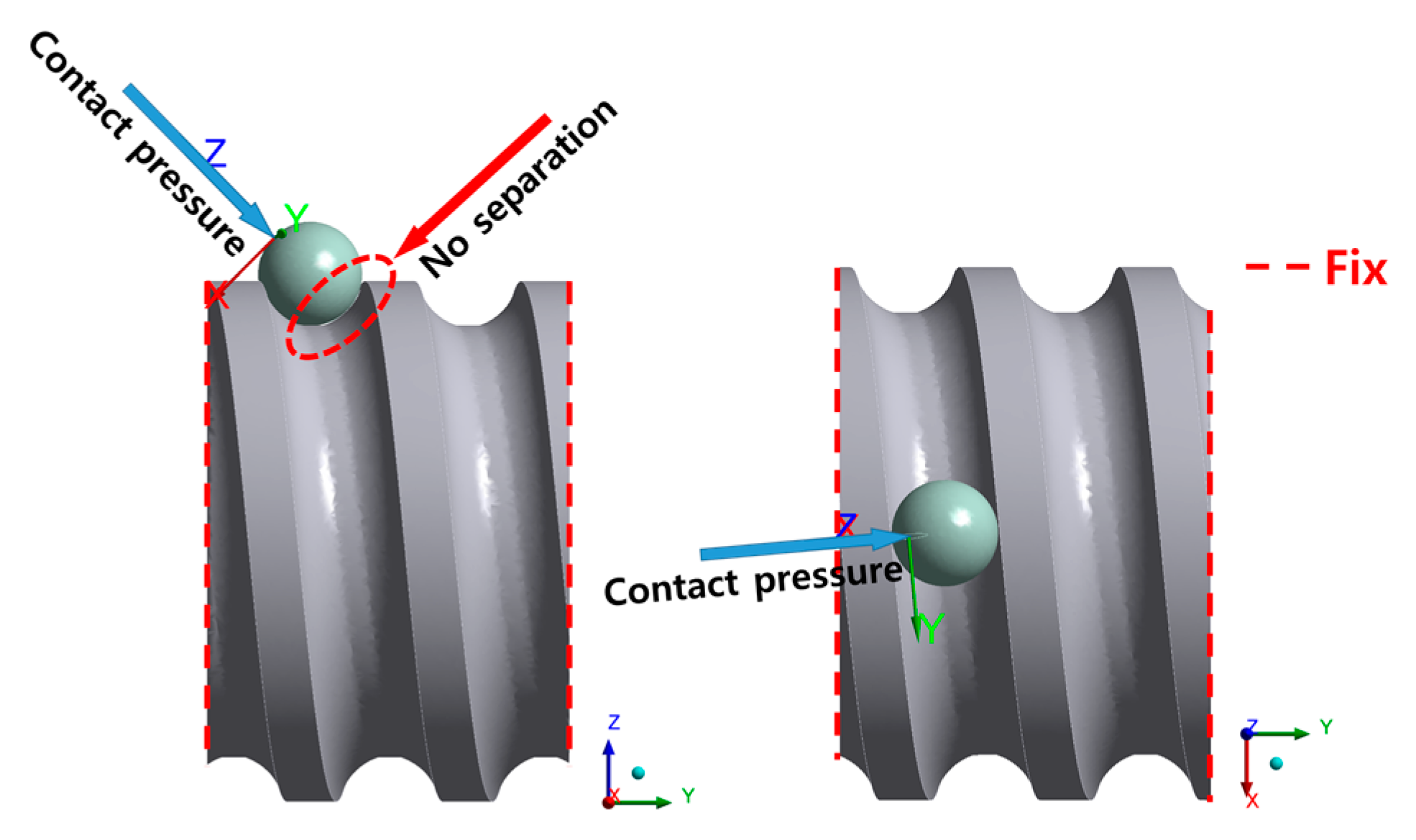
3.2.2. Contact Condition Applied Model
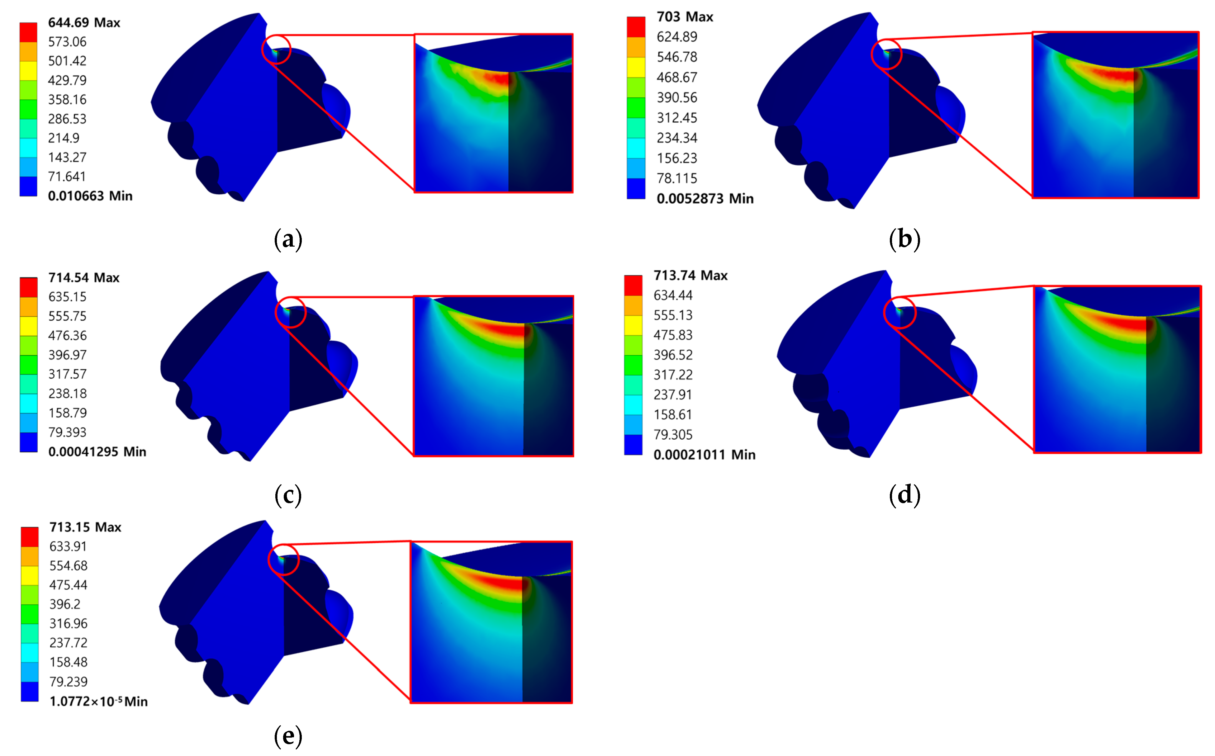
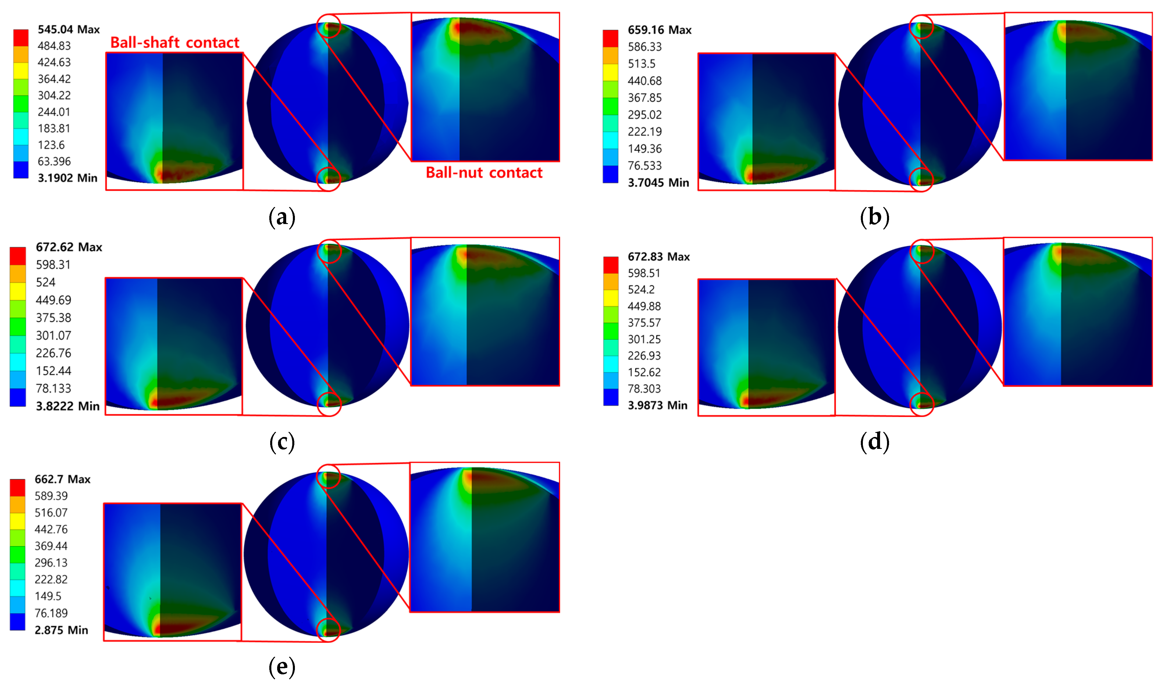
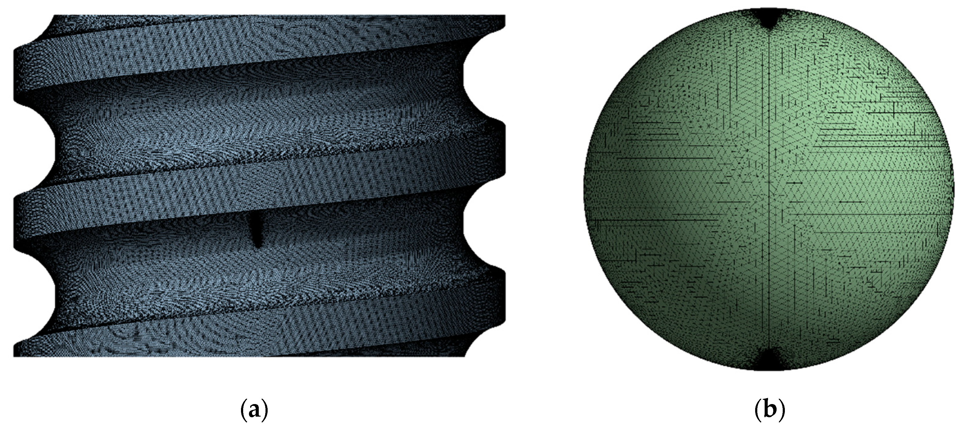
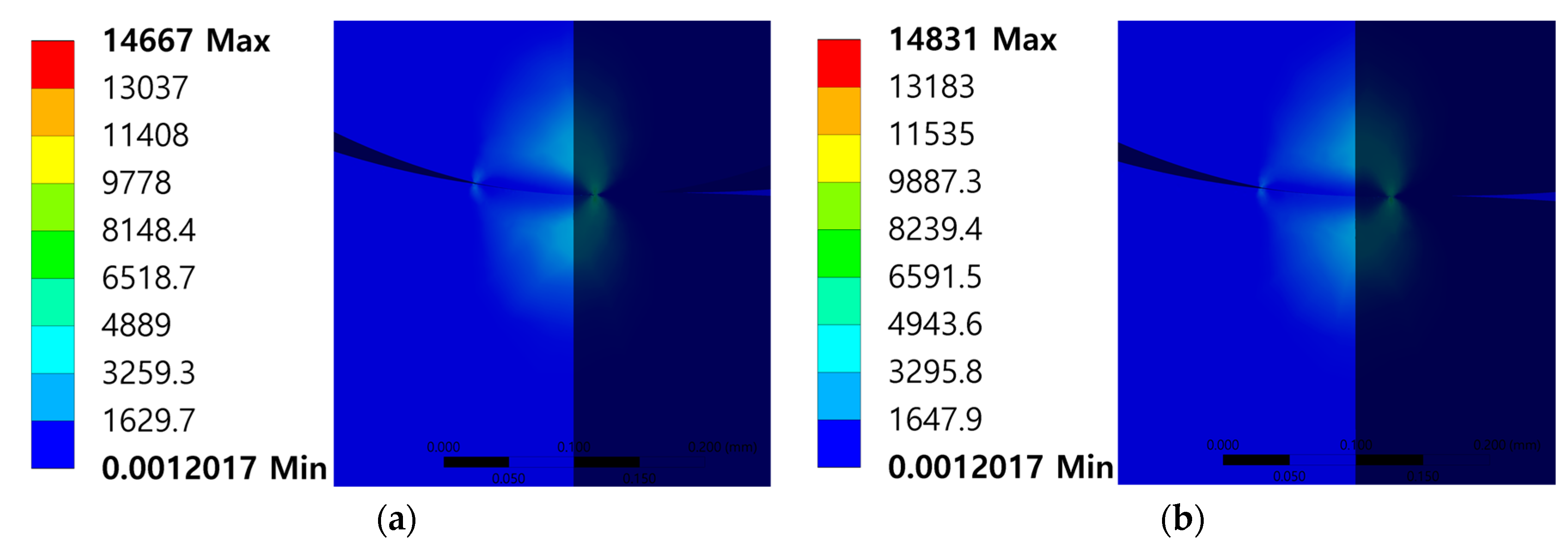
3.3. Results and Discussion
4. Conclusions and Future Works
Author Contributions
Funding
Institutional Review Board Statement
Informed Consent Statement
Data Availability Statement
Conflicts of Interest
Nomenclature
| The number of balls between shaft and nut | |
| Axial load | |
| Normal load | |
| Contact angle | |
| Lead angle | |
| Semi major axis of contact ellipse | |
| Semi minor axis of contact ellipse | |
| Equivalent radius in the rolling direction | |
| Transversal equivalent radius | |
| Radii ratio | |
| Ball diameter | |
| Pitch circle diameter of balls | |
| Curvature parameter for the shaft race | |
| Curvature parameter for the nut race | |
| Equivalent elastic modulus | |
| Elastic modulus of shaft | |
| Elastic modulus of ball | |
| Elastic modulus of nut | |
| Poisson’s ratio of shaft | |
| Poisson’s ratio of ball | |
| Poisson’s ratio of nut | |
| Max contact pressure | |
| Local contact pressure |
References
- Precision Machinery & Parts e-Project Team. Ball Screw Guide Introduction; NSK Ltd.: Tokyo, Japan, 2016. [Google Scholar]
- Bogdan, L.; Telea, D.; Barbu, Ş. Management and motion control of ball screw actuators applied in the robotic structures. Robot. Manag. 2012, 17, 14–17. [Google Scholar]
- Wei, C.C.; Lin, J.F. Kinematic analysis of the ball screw mechanism considering variable contact angles and elastic deformations. J. Mech. Des. 2003, 125, 717–733. [Google Scholar] [CrossRef]
- Lazović, T.; Milović, S.V.L. Contact stresses and deformations in thrust ball bearing. Mach. Des. 2018, 10, 85–92. [Google Scholar]
- Du, Y.; Chen, L.; McGruer, N.E.; Adams, G.G.; Etsion, I. A finite element model of loading and unloading of an asperity contact with adhesion and plasticity. J. Colloid Interface Sci. 2007, 312, 522–528. [Google Scholar] [CrossRef] [PubMed]
- Daidié, A.; Chaib, Z.; Ghosn, A. 3D simplified finite elements analysis of load and contact angle in a slewing ball bearing. J. Mech. Des. 2008, 130, 082601. [Google Scholar] [CrossRef]
- Azianou, A.E.; Debray, K.; Bolaers, F.; Chiozzi, P.; Palleschi, F. Modeling of the behavior of a deep groove ball bearing in its housing. J. Appl. Math. Phys. 2013, 1, 45–50. [Google Scholar] [CrossRef]
- Zhaoping, T.; Jianping, S. The contact analysis for deep groove ball bearing based on ANSYS. Procedia Eng. 2011, 23, 423–428. [Google Scholar] [CrossRef] [Green Version]
- Šulka, P.; Sapietová, A.; Dekýš, V.; Sapieta, M. Static structural analysis of rolling ball bearing. MATEC Web Conf. 2018, 244, 01023. [Google Scholar] [CrossRef]
- Xu, N.; Tang, W.; Chen, Y.; Bao, D.; Guo, Y. Modeling analysis and experimental study for the friction of a ball screw. Mech. Mach. Theory 2015, 87, 57–69. [Google Scholar] [CrossRef]
- Wang, Y.; Wang, W.; Zhang, S.; Zhao, Z. Investigation of skidding in angular contact ball bearings under high speed. Tribol. Int. 2015, 92, 404–417. [Google Scholar] [CrossRef]
- Oh, K.J.; Cao, L.; Chung, S.C. Explicit modeling and investigation of friction torques in double-nut ball screws for the precision design of ball screw feed drives. Tribol. Int. 2020, 141, 105841. [Google Scholar] [CrossRef]
- Jackson, R.L.; Ghaednia, H.; Lee, H.; Rostami, A.; Wang, X. Tribology for Scientists and Engineers; Springer: New York, NY, USA, 2013. [Google Scholar]
- Habchi, W.; Demirci, I.; Eyheramendy, D.; Morales-Espejel, G.; Vergne, P. A finite element approach of thin film lubrication in circular EHD contacts. Tribol. Int. 2007, 40, 1466–1473. [Google Scholar] [CrossRef]
- Luo, H.; Fu, J.; Jiao, L.; Zhao, F. Theoretical calculation and simulation analysis of axial static stiffness of double-nut ball screw with heavy load and high precision. Math. Probl. Eng. 2019, 2019, 9608794. [Google Scholar] [CrossRef]
- Greenwood, J.A. Analysis of elliptical Hertzian contacts. Tribol. Int. 1997, 30, 235–237. [Google Scholar] [CrossRef]
- Houpert, L. Numerical and analytical calculations in ball bearings. In Proceedings of the 8th European Space Mechanism and Tribology Symposium, Toulouse, France, 1 September 1999. [Google Scholar]
- Harris, T.A. Rolling Bearing Analysis, 4th ed.; John Wiley and Sons: New York, NY, USA, 2001. [Google Scholar]
- Olaru, D.; Puiu, G.C.; Balan, L.C.; Puiu, V. A new model to estimate friction torque in a ball screw system. Prod. Eng. 2006, 3, 333–346. [Google Scholar]
- ANSYS Inc. Contact Technology Guide; ANSYS Inc.: Canonsburg, PA, USA, 2004. [Google Scholar]
- ANSYS Inc. Theory Reference for the Mechanical APDL and Mechanical Applications; ANSYS Inc.: Canonsburg, PA, USA, 2009. [Google Scholar]
- Ostertag, O.; Frankovský, P.; Ostertagová, E.; Trebuňa, F. Application of the harmonic star method in photoelastic separation of principal stresses. Appl. Opt. 2016, 55, 425–431. [Google Scholar] [CrossRef] [PubMed]


| Parameter | Value |
|---|---|
| The number of balls between shaft and nut | 42 |
| Contact angle | 49.0495° |
| Ball diameter | 2 mm |
| Pitch circle diameter of balls | 10.3 mm |
| Curvature parameter | 0.515 |
| Parameter | STS440C | SUJ2 | |
|---|---|---|---|
| Shaft | Nut | Ball | |
| Elastic modulus (GPa) | 200 | 210 | |
| Poisson’s ratio | 0.283 | 0.28 | |
| Yield strength (MPa) | 1280 | 1176 | |
| UTS (MPa) | 1750 | 1274 | |
| Type | Ball-Shaft Contact | Ball-Nut Contact |
|---|---|---|
| Max. contact stress (MPa) | 1178.2 | 1058.2 |
| Type | Ball-Shaft Contact | Ball-Nut Contact |
|---|---|---|
| Semi major axis (mm) | 0.4611 | 0.4442 |
| Semi minor axis (mm) | 0.0411 | 0.0475 |
| Types | Contact Surface Mesh Size (mm) | Other Mesh Size (mm) | Max. Equivalent Stress of Shaft (MPa) | Max. Equivalent Stress of Ball (MPa) |
|---|---|---|---|---|
| Type1 | 0.016 | 0.32 | 644.69 | 545.04 |
| Type2 | 0.008 | 0.16 | 703 | 659.16 |
| Type3 | 0.004 | 0.08 | 714.54 | 672.62 |
| Type4 | 0.002 | 0.04 | 713.74 | 672.83 |
| Type5 | 0.001 | 0.02 | 713.15 | 662.7 |
Publisher’s Note: MDPI stays neutral with regard to jurisdictional claims in published maps and institutional affiliations. |
© 2022 by the authors. Licensee MDPI, Basel, Switzerland. This article is an open access article distributed under the terms and conditions of the Creative Commons Attribution (CC BY) license (https://creativecommons.org/licenses/by/4.0/).
Share and Cite
Shin, G.-H.; Hur, J.-W. A New Finite Element Analysis Model to Estimate Contact Stress in Ball Screw. Appl. Sci. 2022, 12, 4713. https://doi.org/10.3390/app12094713
Shin G-H, Hur J-W. A New Finite Element Analysis Model to Estimate Contact Stress in Ball Screw. Applied Sciences. 2022; 12(9):4713. https://doi.org/10.3390/app12094713
Chicago/Turabian StyleShin, Geon-Ho, and Jang-Wook Hur. 2022. "A New Finite Element Analysis Model to Estimate Contact Stress in Ball Screw" Applied Sciences 12, no. 9: 4713. https://doi.org/10.3390/app12094713
APA StyleShin, G.-H., & Hur, J.-W. (2022). A New Finite Element Analysis Model to Estimate Contact Stress in Ball Screw. Applied Sciences, 12(9), 4713. https://doi.org/10.3390/app12094713