Article

Characterization of Microstructure, Weld Heat Input, and Mechanical Properties of Mg–Al–Zn Alloy GTA Weldments

by
Nagumothu Kishore Babu
1,*,
Mahesh Kumar Talari
1,
Prakash Srirangam
2,
Abdullah Yahia AlFaify
3 and
Ateekh Ur Rehman
3,*
1
Department of Metallurgical and Materials Engineering, National Institute of Technology, Warangal 506004, Telangana, India
2
Warwick Manufacturing Group, University of Warwick, Coventry CV4 7AL, UK
3
Industrial Engineering Department, College of Engineering, King Saud University, P.O. Box 800, Riyadh 11421, Saudi Arabia
*
Authors to whom correspondence should be addressed.
Appl. Sci. 2022, 12(9), 4417; https://doi.org/10.3390/app12094417
Submission received: 7 April 2022 / Revised: 20 April 2022 / Accepted: 25 April 2022 / Published: 27 April 2022
(This article belongs to the Special Issue Metal Additive Manufacturing and Welding)

Abstract

:
The present study investigated the influence of welding speed on the microstructure, hardness, and tensile properties of the AZ31 Mg alloy gas tungsten arc (GTA) welds that were prepared using alternating current (AC). A microstructural examination of the weld metal and base metal was performed using stereo, optical, and scanning electron microscopy (HR-SEM and EDS) techniques. The microstructure of all fusion zones consists of two parts: a columnar zone, adjacent to the fusion boundary, and equiaxed grains, in the centre of the weld fusion zone. It is shown that the average width of the equiaxed zone present at the centre of the fusion zone increases with increasing welding speed. Metallographic examination shows that the highest welding speed (5 mm/s) results in the smallest average grain size. The welds prepared with high welding speed exhibit an increase in strength, hardness, and ductility compared with other welding speeds, which is attributed to low heat input.

1. Introduction

Magnesium alloys display exceptional engineering properties because of their high specific strength, good machinability, stiffness, damping capacity, good weldability, and castability. These properties make them attractive for various industries, such as automobiles, aerospace, and electronics [1,2]. However, these alloys possess poor formability, due to insufficient slip systems in the hexagonal close-packed (hcp) lattice at room temperature, which limits widespread application [3,4]. Gas tungsten arc (GTA), metal inert gas (MIG), laser beam, electron beam, friction, friction stir, stud, spot welding, laser hybrid welding, and ultrasonic welding techniques are reported in the literature for the welding of Mg alloys [5,6,7,8,9,10,11]. The main problems of magnesium welding are in-flammability, oxide film formation, solidification cracking, columnar grains in the fusion zone, and porosity during solidification. The GTA welding technique used in this study has several advantages (good weld quality) over the other arc welding processes [12,13,14].
Sun et al. [15] study the influence of different welding techniques (GTA, CO2, and Nd: YAG laser) on the microstructure and mechanical properties of Mg–Al–Zn welds. They report that laser welds produce fine grain size compared to the GTA welds. It is observed that hardness reduction in the fusion zone (FZ) and the heat-affected zone (HAZ), compared with the base metal, is evident in GTA and laser welding techniques, attributed to the loss in strengthening effect of the weld thermal cycle. The influence of welding techniques, such as alternating current (AC), variable polarity mixed (VPM), alternating current pulsing (ACPC), and variable polarity (VP) techniques on the microstructure and mechanical properties of AZ31 GTA welds are reported by Babu et al. [16]. They show that ACPC results in significant grain refinement compared with un-pulsed welds. It is also shown that improved tensile strength, hardness, and ductility of ACPC welds are associated with the grain refinement mechanism obtained by weld pool agitation and dendrite fragmentation. Wen et al. [17] investigate the influence of high-frequency vibration on the microstructure and mechanical properties (hardness and strength) of AZ31 alloy GTA welds. They suggest that the degree of grain refinement increases with the increased vibration amplitude, strongly affected by wave energy transferring to the weld pool. Yuan et al. [18] conduct detailed studies on grain refinement of AZ31 and AZ91 GTA welds using the arc oscillation technique. They observe that significant grain refinement is achieved through dendrite fragmentation. It is also shown that constitutional supercooling is significant in AZ91 welds, due to the high Al content compared to AZ31 welds. Quan et al. [19] show that with decreasing heat input, the tensile strength of AZ31 laser welds increases, due to fast cooling rates and moderate concentration of precipitates. They report that the AZ31 alloy melt quickly solidifies because of rapid cooling employed in laser welding, and results in the precipitation of the Mg17Al12 phase. Padmanabhan et al. [20] compare and correlate the microstructure, hardness, and tensile properties of friction stir welded (FSW) AZ31B Mg with fusion welding techniques (GTA and laser welding). They report that the laser beam welded joints exhibit superior tensile properties (yield strength (YS): 174 MPa, ultimate tensile strength (UTS): 212 MPa and % elongation (% El): 12.1) compared to GTA welds (YS: 148 MPa, UTS: 183 MPa, % El: 7.6) and FSW joints (YS: 171 MPa, UTS: 208 MPa, % El: 11.8), which is attributed to the fine grains present in the fusion zone [20]. Liu and Dong [21] prepared AZ31 alloy GTA welds, with both AZ61 filler wire and without any filler. The welds prepared with AZ61 filler exhibit a UTS of 94% of base metal compared to welds without filler (90% of base metal). They report that the microstructure of AZ61 filler welds show a reduction in grain size of HAZ, compared with welded joints made without filler [21]. Subravel et al. [22] investigate the influence of welding speed on the microstructure and mechanical properties of AZ31 GTA welds prepared with a pulsing technique. They found that the welded joint prepared using a high welding speed of 135 mm/min exhibit superior tensile properties (YS: 189 MPa, UTS: 193 MPa, % El: 4.5) compared with low welding speed (YS: 143 MPa, UTS: 183 MPa, % El: 5.5). They observe that the superior mechanical properties of welds prepared with a welding speed of 135 mm/min are because of the fine grains and finely dispersed precipitates in the weld [22]. Chai et al. [23] report that post-weld hot rolling of AZ31 GTA welds show improved mechanical properties (YS: 240 MPa, UTS: 297 MPa, % El: 3.5) compared to no post-weld rolling (YS: 108 MPa, UTS: 172 MPa, % El: 1.4). The superior mechanical properties after post-weld hot rolling are attributed to the strain hardening and twin boundaries. However, the ductility of the post-weld rolled weldments is lower than the base metal (YS: 167 MPa, UTS: 251 MPa, % El: 19).
The mechanical properties of the welds are adversely impaired by columnar and coarse dendritic microstructures in the fusion zones. For better mechanical properties of the weldments, columnar grains should be replaced with fine equiaxed grains. It is well known that the ratio of G/R, where R is the growth rate, and G is the thermal gradient, determines the morphology of solidification in any given alloy [23]. Various techniques (ultrasonic vibration, double-sided arc welding, magnetic oscillation, exciting the electric arc) were employed to promote columnar to equiaxed transition, and enhance the % of equiaxed grains in the weld [24,25,26,27]. However, changing the welding parameters, and the addition of inoculants, are the most common and straightforward strategies employed in industrial welding practice. Welding speed is a crucial parameter in GTA welding because it determines the full penetration with no excessive heat build-up. Increasing welding speed also allows for more constitutional supercooling at the solidification front, which aids in heterogeneous nucleation and grain refinement in the welds [28,29]. There are few studies on the impact of weld heat input on the grain refinement of Mg welds. The present study evaluated the effect of weld heat input on the microstructure, hardness, and tensile properties of AZ31 GTA weldments. Further, the effect of the welding speed, and consequent variation in weld heat input, was correlated to the thermal history and the grain refinement of the fusion zone.

2. Materials and Methods

The current study used sheets of 3 mm thick, rolled AZ31 magnesium alloy for welding experiments. Table 1 shows the chemical composition of the AZ31 base metal. A sheet with dimensions of 120 × 100 × 3 mm was used for welding coupons. Prior to welding, these coupons were wire-brushed and cleaned with acetone. A GTA welding machine (ORIGO TIG 4300Iw AC/DC, Esab India Ltd., Chennai, India) was employed for welding AZ31 coupons, using a 2.4 mm ϕ tungsten electrode. Full-penetration autogenous welds were made on the coupons. The machine had an electromechanical linear movement set up for moving the welding torch. Welding was carried out so that the weld beads were oriented perpendicular to the rolling direction. Ar was used as the shielding gas, and 50% Ar + 50% He mixture was used for the auxiliary trailing and backing gas, improving the weld quality. The gas flow rate of 20 l/min was maintained for the trailing and backing gas shields, and the shielding gas flow rate was 15 L/min. After completion of welding, the shielding gas was allowed to flow for another minute to prevent the oxidation of welded area, while the welded coupon cooled to room temperature. A K-type thermocouple of 0.2 mm diameter wire was attached to the back of the weldment to measure the temperature history curves, which were then recorded by a high-speed computer-based data-acquisition system connected to a personal computer. Table 2 contains a list of the welding parameters. Heat input values were calculated using the formula: heat input = (V × I)/S kJ/mm, where V is the voltage used, in volts, I is the current used, in amperes, and S is the weld travel speed (mm/s), for all the weldments.
The samples for optical microscopy were appropriately sectioned, mounted, mechanically polished, and etched for microstructural analysis. For the microstructure examination of samples, a solution containing 10 mL H2O, 10 mL acetic acid, 4.2 g picric acid, and 70 mL ethanol was used for etching. The etched samples were observed using a Nikon SMZ745T stereomicroscope to the macrograph of the welds. A Leitz optical microscope was used to examine the microstructure of the base metals and welds. A scanning electron microscope, with an energy dispersive X-ray spectrometer (EDS), was used to examine the weld microstructure and tensile fracture surfaces. A PANalytical X-ray diffractometer with Cu kα radiation was employed for the identification of the various phases present in the weld region and base metal.
A Vickers microhardness tester (Shimadzu corporation, HMV-G20S (E, 230V), Japan), with a diamond pyramid indenter, was used to measure the microhardness of the specimens. The microhardness investigation of the welded samples was made across the weld region at intervals of 0.5 mm for 15 s, under a load of 1000 g. Tensile specimens were made from base metal and as-welded coupons in accordance with the ASTM E 8M standard. The tensile tests were carried out using a universal testing machine at room temperature for the samples with a 1 mm/min crosshead speed. The gauge length, gauge width, and thickness of the transverse tensile weld specimens were 25 mm, 6 mm, and 3 mm, respectively.

3. Results and Discussion

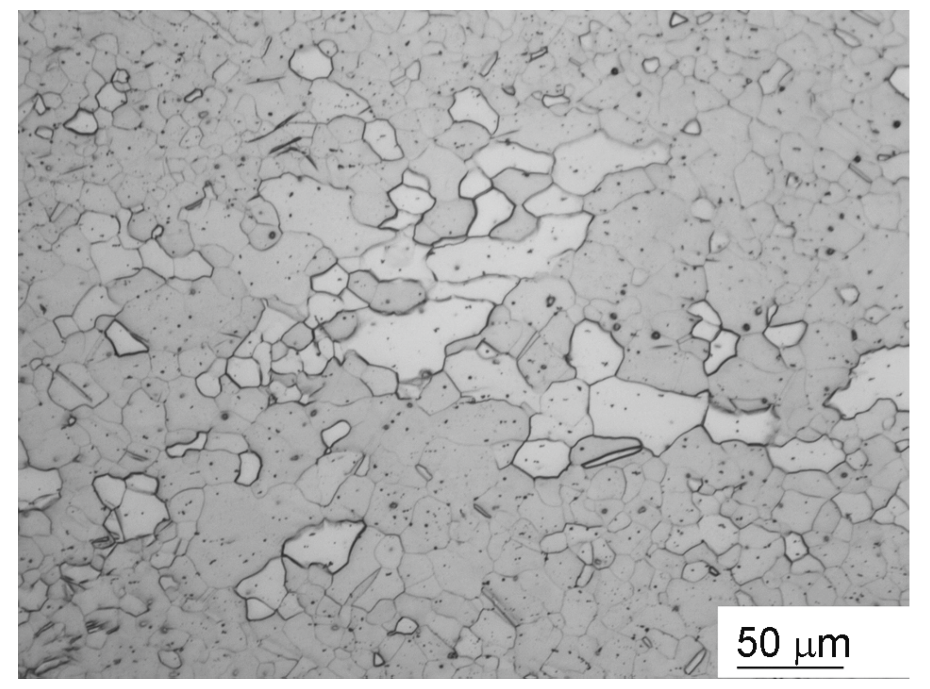
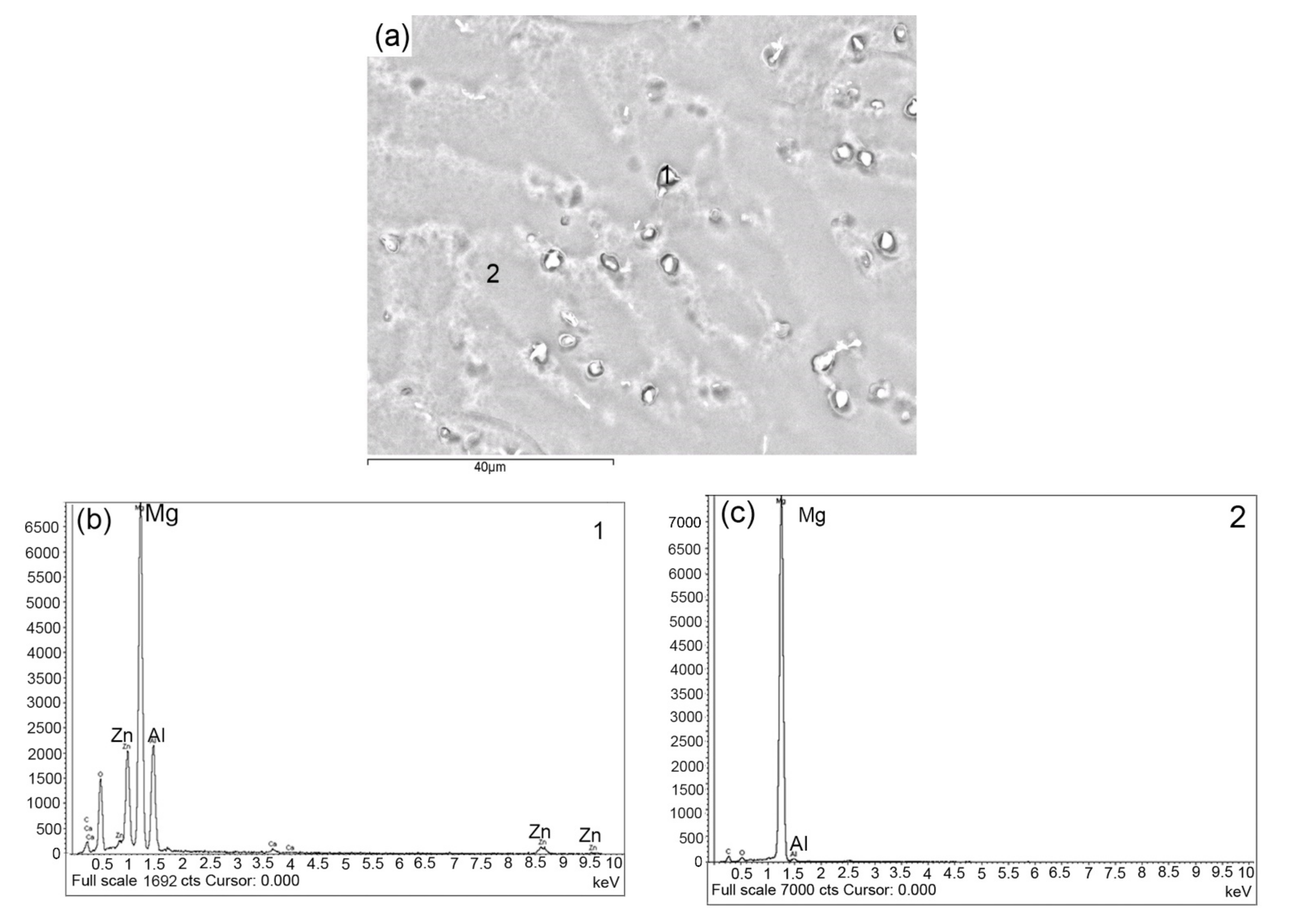
3.1. Base Metal Microstructure

Figure 1 shows the optical microstructure of the AZ31 base metal consisting of alpha equiaxed grains. The average grain size is 25 ± 12 µm. A small amount of fine Al8Mn5 particles is uniformly distributed throughout the wrought base metal [30].

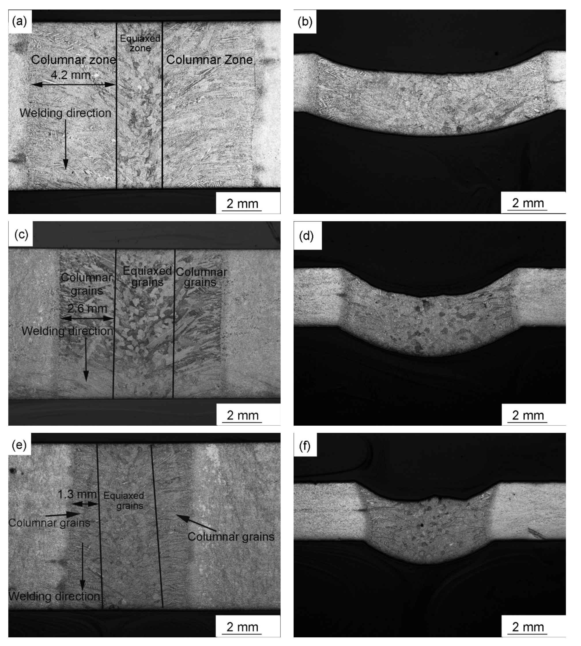
3.2. Weld Zone Macrostructure

The macrostructures of the top surface and cross-section of the fusion zone for welds prepared using different welding speeds are shown in Figure 2. The full-penetration weld joints without any cracks were obtained in this study using different welding speeds, as shown in Figure 2a–f. The average weld bead widths of 11, 8, and 6 mm are obtained for the different welding speeds of 3, 4, and 5 mm/s, respectively, as shown in Figure 2a,c,e. When the welding speed is 3 mm/s, the weld bead width is relatively wide compared to welding speeds of 4 and 5 mm/s. The weld bead width decreases with increasing welding speed, strongly affected by the heat input. In other words, the weld bead width decreases with reducing heat input. Furthermore, as shown in Figure 2e,f, some pores are present in the fusion zone. Surface contamination and hydrogen released from the solid phase during the solidification could be responsible for pore formation [31].
The macrostructure of all fusion zones consists of two parts: a columnar zone at the fusion boundary and equiaxed grains in the centre of the weld fusion zone, as shown in Figure 2a–f. The columnar grains are aligned nearly perpendicular to the fusion boundary, where the temperature gradients (G) are steepest. Weld metal solidification in fusion welds frequently occurs in a columnar mode, at the fusion boundary, due to the presence of sharp thermal gradients, and the epitaxial growth process [32]. The temperature gradient is less steep at the centre of the fusion zone compared to the fusion boundary, and results in equiaxed grains at the weld centre. It is well known that increasing the welding speed (low heat input) increases the extent of constitutional supercooling [33]. From Figure 2, it is clear that the columnar grains grow in a direction that is nearly perpendicular to the fusion line, and the columnar zone width decreases with increasing welding speed. In other words, the width of the equiaxed zone increases with decreasing heat input. The welds prepared with a welding speed of 3 mm/s exhibit a large width of the columnar zone (4.2 mm), compared with the welding speeds of 4 mm/s and 5 mm/s (2.6 mm and 1.3 mm, respectively, as shown in Figure 2a,c,f). The heat inputs used for the GTA welds in this study are 421, 316, 253 J/mm, with a corresponding welding speed of 3, 4, and 5 mm/s, respectively. The weld metal cooling rates are inversely proportional to heat input [34]. In other words, as the welding speed increases, the cooling rate increases. Less heat input due to increased welding speed results in a lower maximum temperature, faster cooling rate, and greater constitutional supercooling, resulting in fine equiaxed grain size. This explains why the fraction of the equiaxed grains in the fusion zone increases as the welding speed increases.

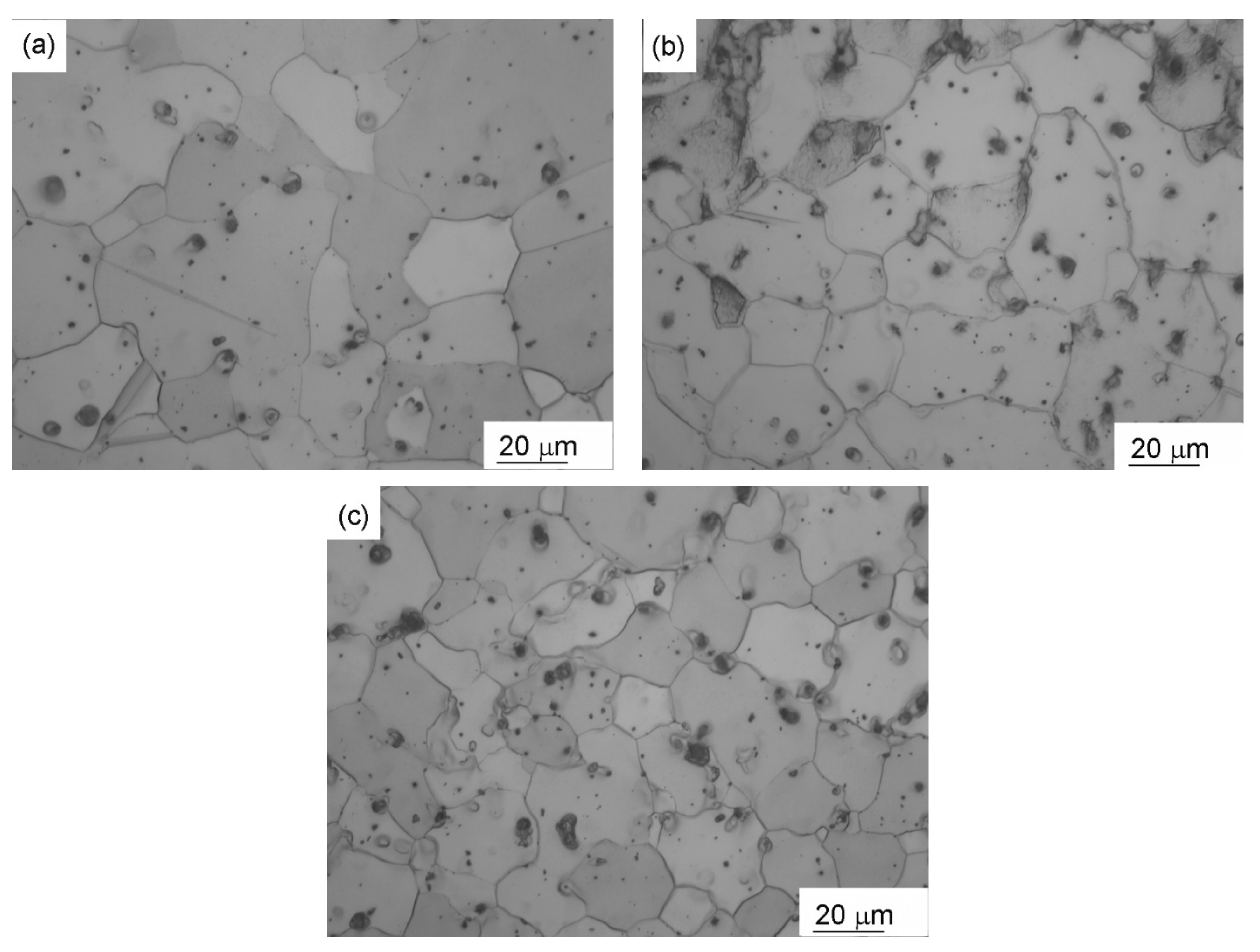
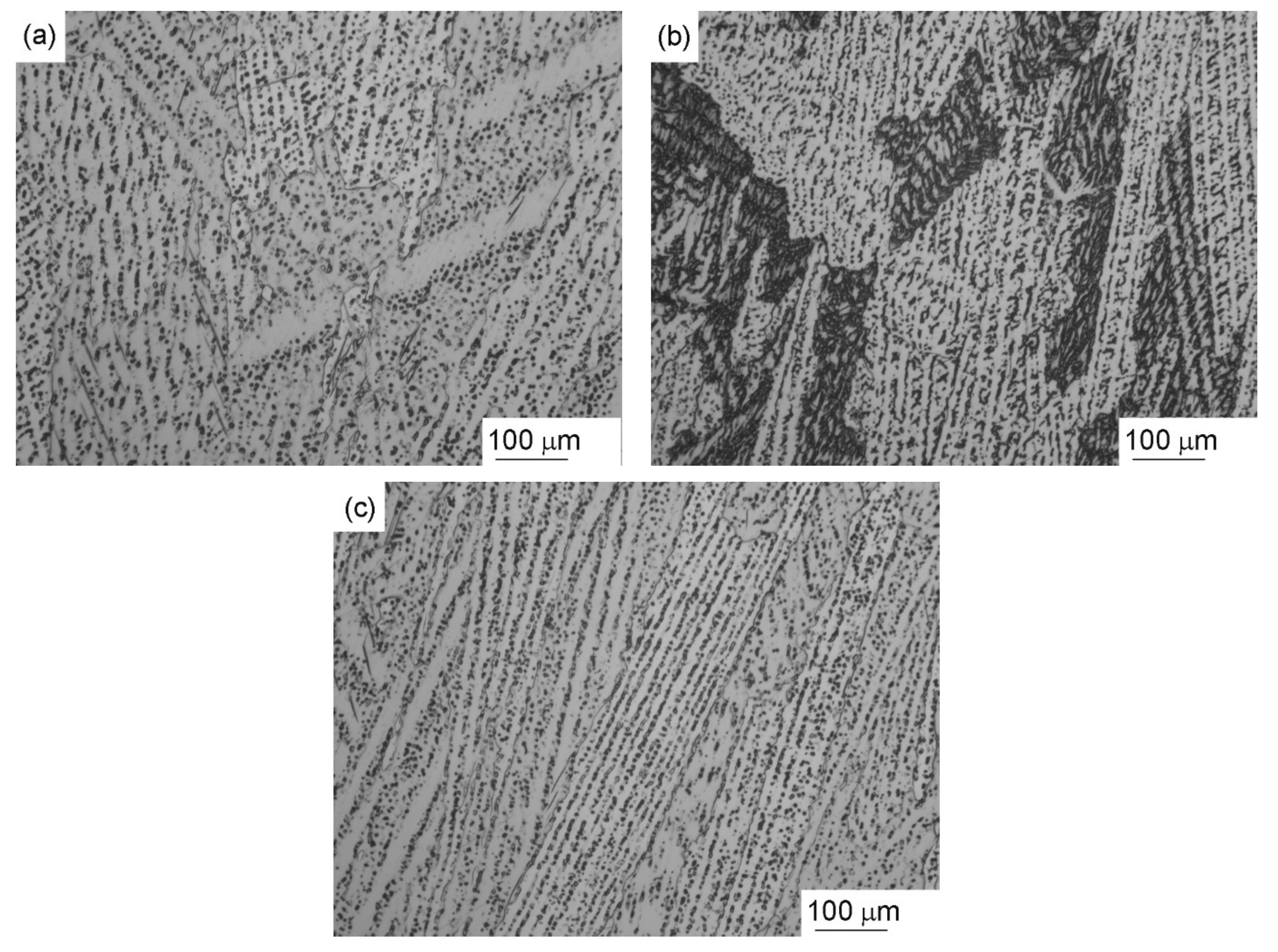
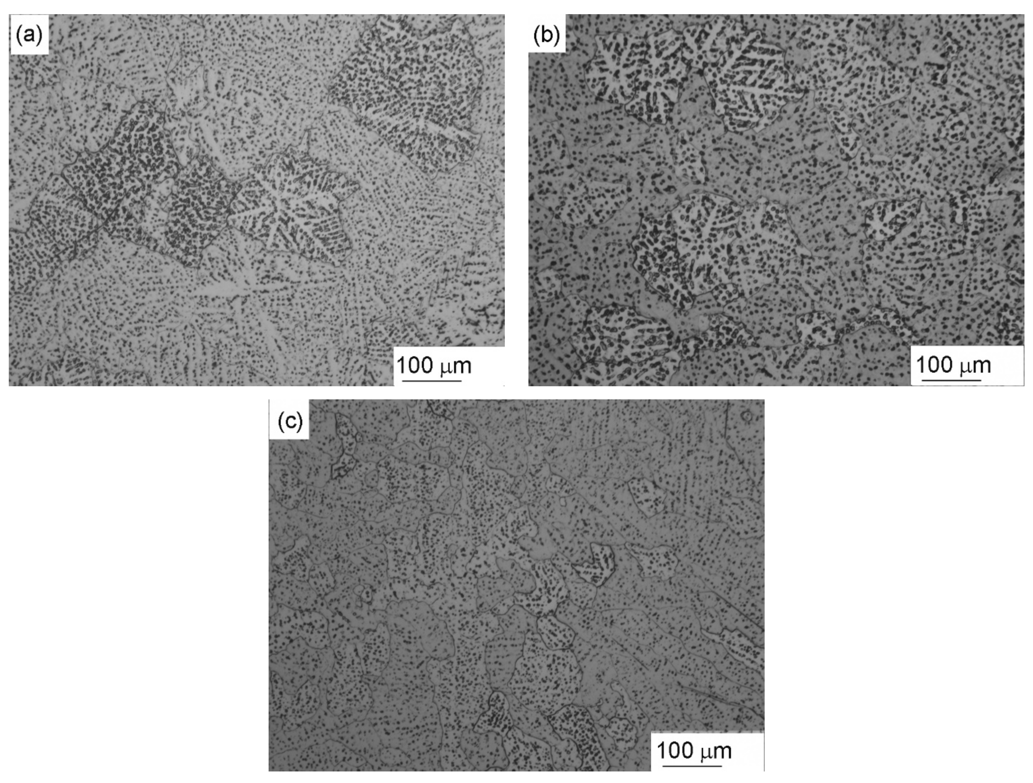
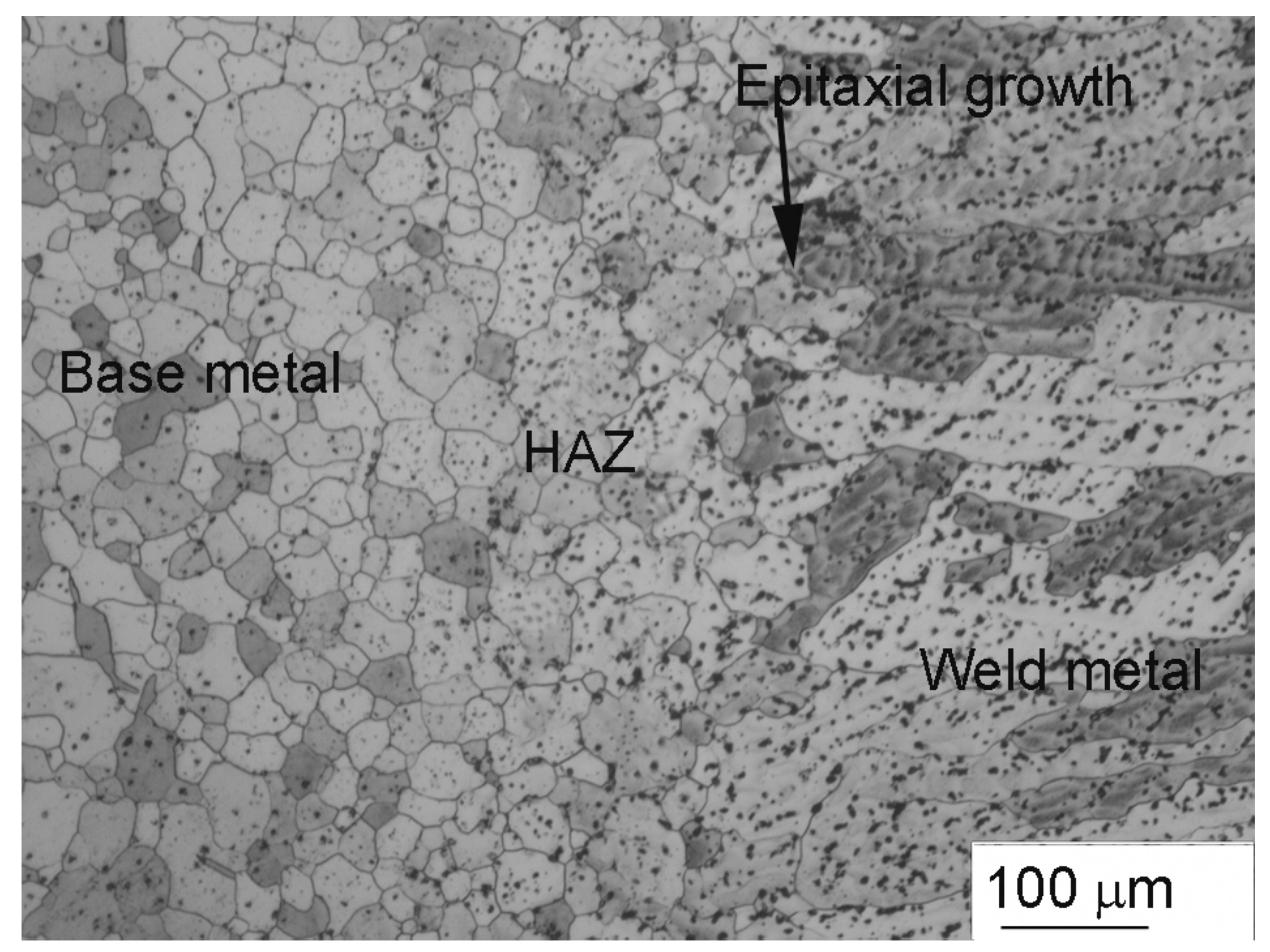
3.3. Weld Zone Microstructure

Figure 3a–c shows the optical microstructures of columnar grains present in the fusion zone for different welding speeds; 3 mm/s, 4 mm/s, and 5 mm/s, respectively. The length/width grain aspect ratio is highest for the welding speed of 5 mm/sec, and lowest for 3 mm/sec. Measurements of the columnar grain size for different welding speeds (3 mm/s, 4 mm/s, and 5 mm/s) show an average columnar grain diameter of 150 μm, 127 μm, and 78 μm, and aspect ratios of between 1–4, 2–4, and 4–11, respectively. Figure 4a–c shows the optical microstructures of equiaxed grains in the fusion zone for welds made at different welding speeds; 3 mm/s, 4 mm/s, and 5 mm/, respectively. The equiaxed zone grain size is highest for the welding speed of 3 mm/sec, and lowest for the welding speed of 5 mm/s. The average grain size values at the weld centre, where equiaxed grains are observed, are 176 ± 57 μm, 115 ± 33 μm, and 90 ± 21 μm for 3 mm/s, 4 mm/s, and 5 mm/s welding speeds, respectively. Figure 4 shows the microstructure of the equiaxed zone for welds made at different welding speeds.
Microstructural analysis reveals that the highest welding speed results in the smallest average grain size. In other words, the grain size decreases as the heat input decreases. In summary, the fusion zone microstructure of the welded joints prepared at different speeds is significantly coarser than the wrought base metal microstructure.
Figure 5 shows the SEM images of the weld fusion zone using a 4 mm/s welding speed. The microstructure is composed of primary α grains surrounded by eutectic mixtures of α and β-Mg17Al12, as shown in Figure 5a. Second phase particles are present within the dendrites in the fusion zone. According to the phase diagram of the Mg–Al, the primary phase is α-Mg, a solid solution containing Al [35]. At 437 °C, a eutectic reaction occurs under equilibrium conditions, which involves the decomposition of the liquid into a two-phase structure composed of a α-Mg and β-Mg17Al12 intermetallic compound. However, the alloy used in the current study (~3 wt.% Al) solidifies into a single-phase α-Mg under equilibrium conditions.
Weld solidification is a non-equilibrium process because of the rapid cooling experienced by the weld pool. During the solidification of the weld metal, nucleation and dendritic growth of the α-Mg phase occurs, and the solute elements Al and Zn are rejected into the liquid adjacent to the solid/liquid interface. Hence, the interdendritic liquid regions are enriched with Al, and reach eutectic composition [36]. As a result, the final solidification occurs near the eutectic composition. EDS analysis in the SEM confirms that these interdendritic regions are observed to be rich in Mg, Al, and Zn (Figure 5b,c), and these particles are identified as β-Mg17Al12 and τ-Mg32(Al, Zn)49 [30]. The XRD pattern of the weld metal corresponding to 3 mm/s welding speed is shown in Figure 6, where the α-Mg and β-Mg17Al12 phases are identified.
Figure 7a–c shows the HAZ optical microstructure of the AZ31 welded joint prepared with different welding speeds. The average grain size is highest for the low welding speed of 3 mm/sec, and lowest for the high welding speed of 5 mm/s. The HAZ average grain size values are 37 μm, 32 μm, and 29 μm for 3 mm/s, 4 mm/s, and 5 mm/s welding speeds, respectively, while the average base metal grain size is 25 μm. The grains are coarsened in the HAZ compared with grain sizes in base metal. According to the Al–Mg binary diagram, the temperature in the HAZ is easily raised to a temperature just below the melting temperature of the alloy. As a result, grain coarsening is frequently observed in the HAZ, which seriously impairs the mechanical properties of welded joints [37]. Less β-phase is observed in the HAZ as the welding speed increased. The width of the HAZ is also affected by the welding speed, and the width of the HAZ gradually narrows as the welding speed increases. This is due to the fact that faster welding speeds result in more rapid cooling rates and less heat input.
Figure 8 compares the microstructure of the base metal, weld metal, and the HAZ of the transverse AZ31 weld joint cross-section prepared with 4 mm/s speed. In the HAZ, grain coarsening is observed compared to the base metal. Second phase particles are present in both the fusion zone and the HAZ within the grains. The un-melted base metal grains act as a substrate for nucleation at the fusion boundary; subsequent epitaxial growth occurs near the fusion boundary, due to the relatively high thermal gradient.

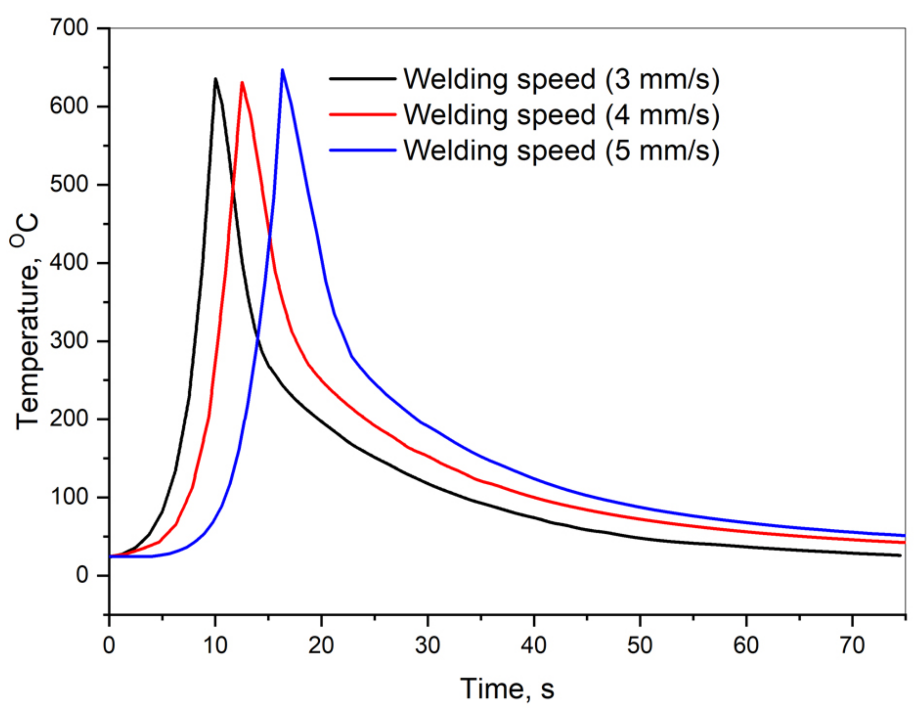
3.4. Thermal Profile
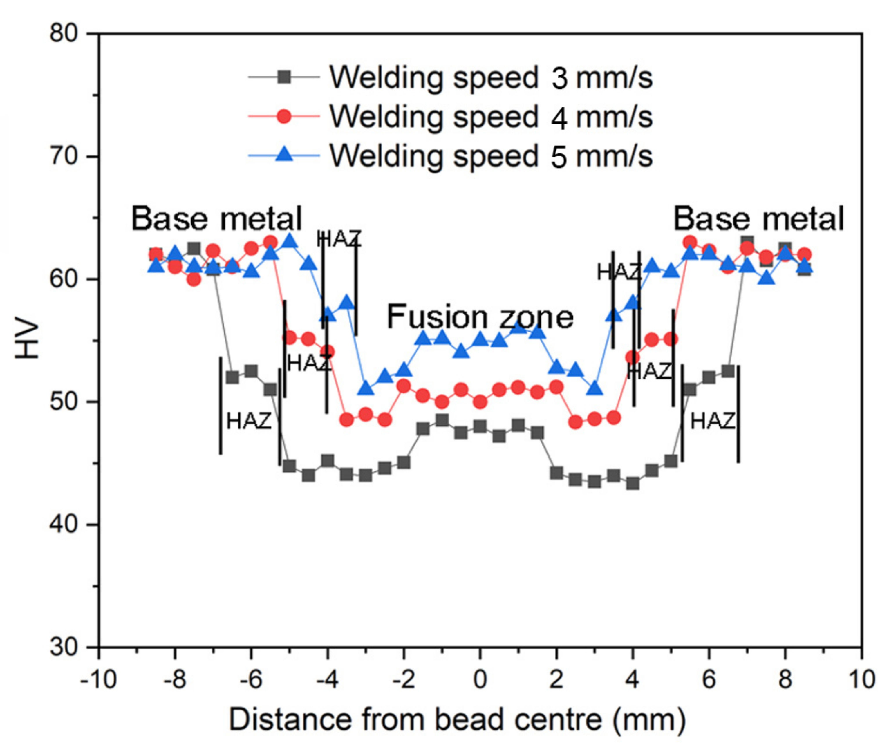
Figure 9 compares the cooling rates measured in the centre of the fusion zone for three different welding speeds (3 mm/s, 4 mm/s, and 5 mm/s). Over the solidification range for AZ31, a welding speed of 5 mm/s demonstrates a faster cooling rate (72 °C/s) than welding speeds of 4 mm/s (87 °C/s) and 3 mm/s (109 °C/s). Higher welding speeds lower the heat input and increase the cooling rates, leading to fine grain structure in the fusion zone. The thermal gradient (cooling rate (G.R)/travel speed (R)) calculated for the different welding speeds of 3, 4, and 5 mm/s are 36 °C/mm, 21 °C/mm, and 14 °C/mm, respectively. The growth rate (R) along the welding direction varies for welding speeds from 3 to 5 mm/s. Thus, the G/R ratio calculated along the welding direction is reduced from 12 °C s/mm2 for a 3 mm/s welding speed, to 2.8 °C s/mm2 for a 5 mm/s welding speed. As discussed earlier, increasing the welding speed significantly increases constitutional supercooling, by lowering the G/R ratio [33]. This results in the larger supercooled liquid regions ahead of the growth front. With the increasing weld travel speed, a lower temperature gradient in the weld pool results in higher constitutional supercooling in the liquid, and promotes the formation of equiaxed grains. The equiaxed grains observed in the current investigation of welds prepared with 5 mm/s may be attributed to a combination of high welding speed (low heat input), and low G/R ratio, by increasing constitutional supercooling.

3.5. Hardness

Figure 10 shows the hardness measurements across the welds prepared with different welding speeds (3 mm/s, 4 mm/s, and 5 mm/s). A reduction in hardness in the fusion zone is evident in all conditions compared to a base metal. The welds prepared with 5 mm/s welding speed (low heat input) exhibit the highest hardness compared with 4 mm/s and 3 mm/s welding speeds. This is attributed to the fine equiaxed dendritic grains and β-precipitates present in the fusion zone. Fine-grain size is critical in magnesium alloys, and is responsible for grain boundary strengthening [38]. The grain boundaries become the primary impediment to the dislocation motion, and materials with fine grain sizes display higher hardness and strength. In all conditions, the equiaxed zone exhibits slightly higher hardness than the columnar zone within the fusion zone. The lower hardness value in the HAZ region, compared to the base metal, is attributed to the coarse grains in all conditions. The width of the HAZ decreases with increasing welding speed because of low heat input. However, the base metal shows the highest hardness values compared to the HAZ and fusion zone in all conditions, and this is attributed to the cold-worked microstructure and fine grain size.

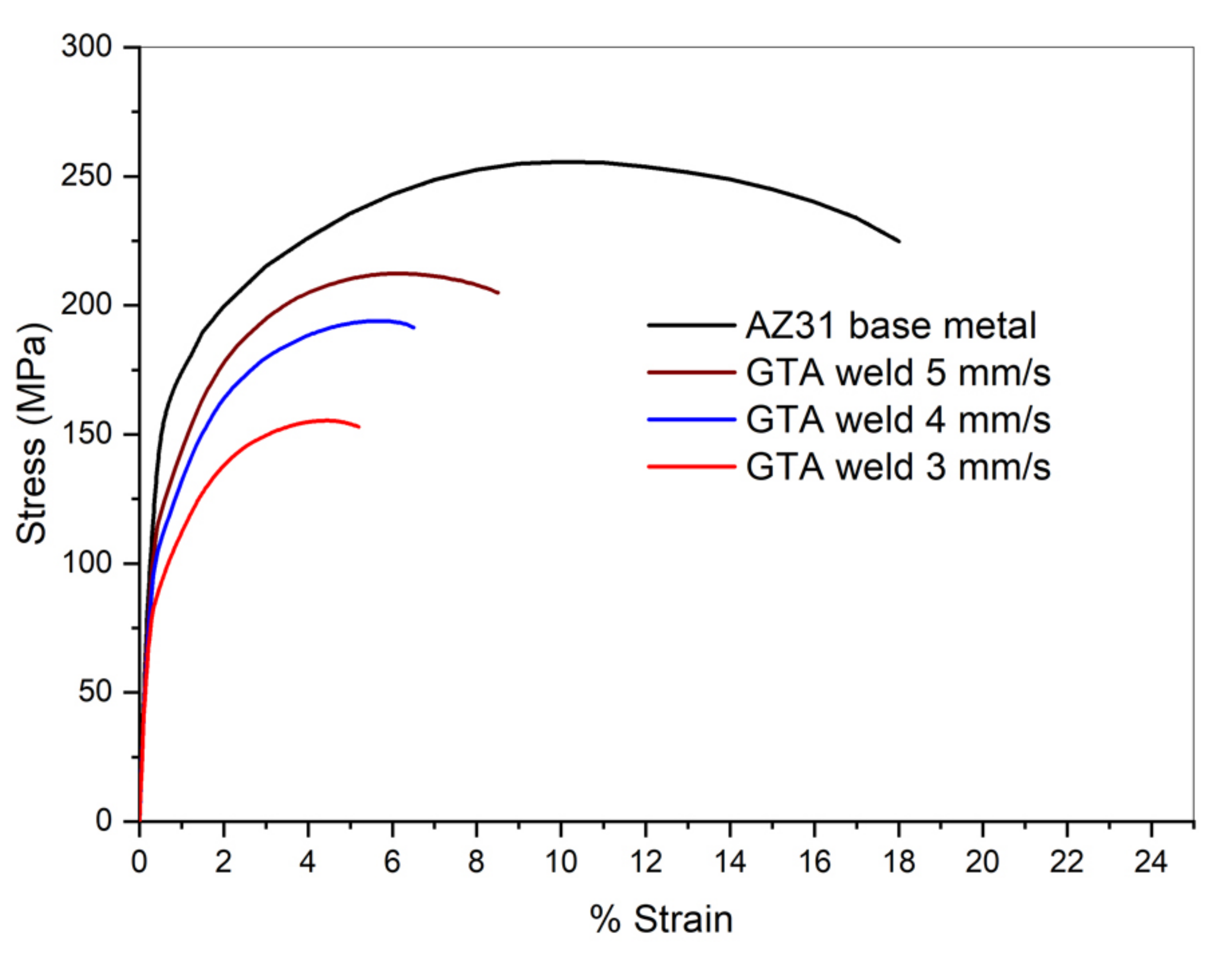
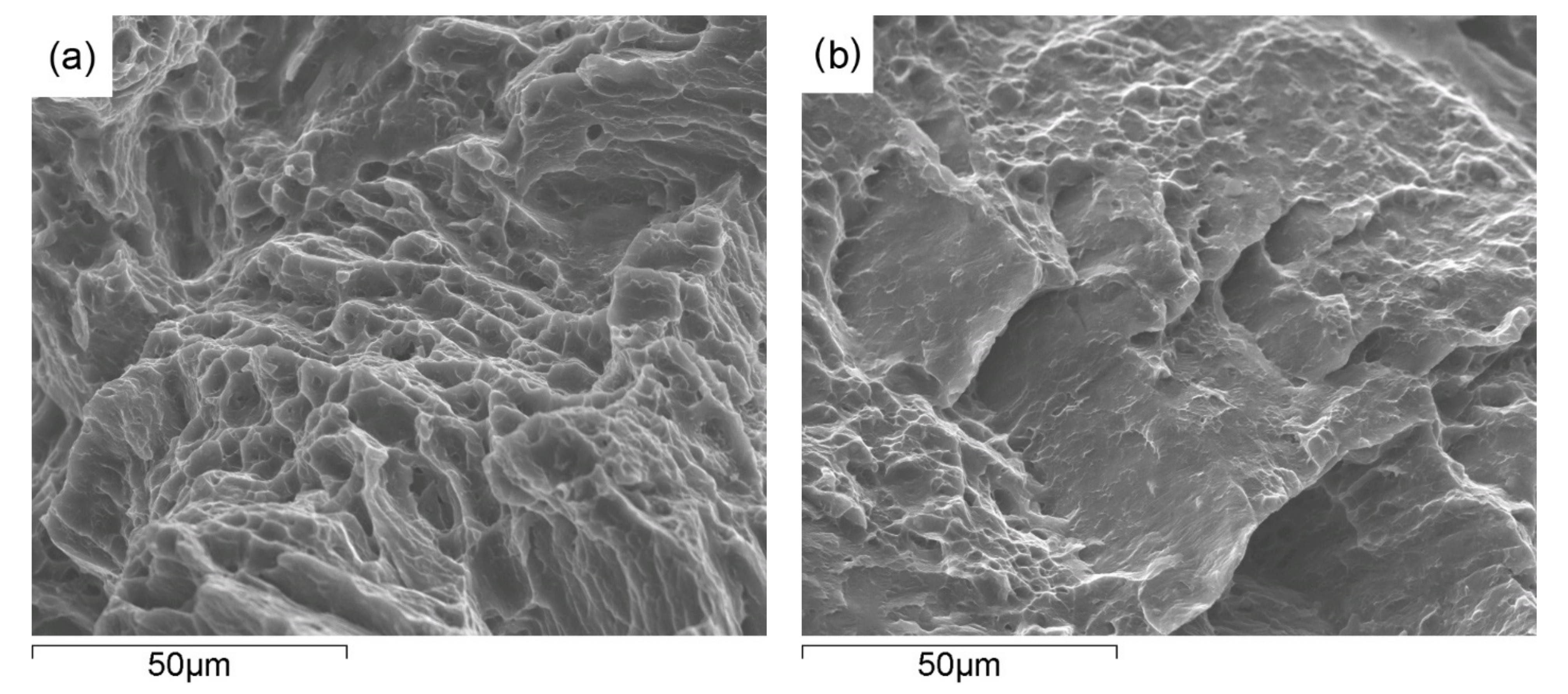
3.6. Tensile Properties

Figure 11 shows the typical stress–strain curves for the AZ31 base metal and GTA welded joints prepared with different weld speeds (3 mm/s, 4 mm/s, and 5 mm/s). The tensile results are listed in Table 3. The weldments prepared with 5 mm/s welding speed (low heat input) exhibit the highest (YS: 160 Mpa, UTS: 215 Mpa, % El: 8) values compared with 4 mm/s (YS: 140 Mpa, UTS: 198 Mpa, % El: 6.5) and 3 mm/s welding speeds (YS: 120 Mpa, UTS: 165 Mpa, % El: 5), and this is attributed to the fine equiaxed dendritic grains and β-precipitates present in the fusion zone. As discussed earlier, lower temperature gradients, G, are observed in the weld pool at higher welding speeds (Figure 9). This results in increased constitutional supercooling, and assists the survival of more of the nuclei and the formation of fine equiaxed grains. However, all welding speeds exhibit lower strength and ductility values compared with the cold-worked base metal. The weld metal shows a typical dendritic microstructure containing eutectic β-Mg17Al12 (intermetallic) particles, which is entirely different from cold-worked wrought base metal. It is worthwhile to note that the weldments display considerably lower strength and ductility values at lower welding speeds (high heat input) than at high welding speed and compared to the base metal. This is attributed to the presence of the coarse columnar dendrites at the edge of the fusion line, and equiaxed dendrites present at the centre of the weld. The tensile fracture surfaces of the welded joints were fabricated with high and low welding speeds (5 mm/s and 3 mm/s), and these are shown in Figure 12a,b, respectively. Figure 12a shows that ductile and very fine dimple fracture features in the AZ31 welded joint prepared with a high welding speed of 5 mm/s (low heat input). Ductile materials show fine dimples on the fracture surface. The welded joints prepared with low heat input welds have a higher ductility compared with high heat input welds. Figure 12b reveals the low ductility fracture surface of welds made with high heat input (3 mm/s).

4. Conclusions

In this study, microstructural analysis, an examination of thermal history, and an evaluation of the mechanical properties of the AZ31 GTA welds prepared with different welding speeds were carried out. The following conclusions were drawn:
  • The GTA welding technique produced sound AZ31 Mg weldments, without any defects, such as solidification cracking or liquation cracking, except in a few scattered pores;
  • The microstructural examination of the fusion zone reveals that the average grain size of the equiaxed zone decreases with increasing welding speed;
  • The welds prepared with high welding speed (low heat input) exhibit improved strength and ductility compared with low welding speeds, due to finer equiaxed dendritic grains;
  • The welds prepared with low welding speed exhibit a reduction in strength and ductility compared with high welding speed. This is attributed to the coarse columnar dendrites present in the fusion zone. However, the AZ31 base metal exhibits good strength and ductility values compared with all welded joints, due to the work hardening effect of the wrought base metal;
  • Increased welding speed lowers the heat input and increases the cooling rates, thereby reducing the temperature gradient G, and increasing constitutional supercooling, to allow more nuclei to survive and grow into fine equiaxed dendritic grains in the fusion zone.

Author Contributions

Conceptualization, N.K.B., M.K.T. and P.S.; methodology, N.K.B., M.K.T., P.S., A.U.R. and A.Y.A.; formal analysis, N.K.B., M.K.T., P.S., A.U.R. and A.Y.A.; investigation, N.K.B., M.K.T., P.S., A.U.R. and A.Y.A.; resources, N.K.B. and M.K.T.; data curation, N.K.B., M.K.T., P.S., A.U.R. and A.Y.A.; writing—original draft preparation, N.K.B., M.K.T. and A.U.R.; writing—review and editing, N.K.B., M.K.T., P.S., A.U.R. and A.Y.A.; visualization, N.K.B., M.K.T. and A.U.R.; supervision, N.K.B., M.K.T. and A.U.R.; project administration, N.K.B. and M.K.T.; funding acquisition, A.U.R. and A.Y.A. All authors have read and agreed to the published version of the manuscript.

Funding

This research was funded by King Saud University through Researchers Supporting Project number (RSP-2021/256), King Saud University, Riyadh, Saudi Arabia.

Institutional Review Board Statement

Not applicable.

Informed Consent Statement

Not applicable.

Data Availability Statement

Not applicable.

Acknowledgments

The authors are thankful to King Saud University for funding this work through Researchers Supporting Project number (RSP-2021/256), King Saud University, Riyadh, Saudi Arabia.

Conflicts of Interest

The authors declare no conflict of interest.

References

  1. Polmear, I.J. Magnesium Alloys and Applications. Mater. Sci. Technol. 1994, 10, 1–16. [Google Scholar] [CrossRef]
  2. Mordike, B.L.; Ebert, T. Magnesium: Properties—Applications—Potential. Mater. Sci. Eng. A 2001, 302, 37–45. [Google Scholar] [CrossRef]
  3. Yoo, M.H.; Agnew, S.R.; Morris, J.R.; Ho, K.M. Non-Basal Slip Systems in HCP Metals and Alloys: Source Mechanisms. Mater. Sci. Eng. A 2001, 319–321, 87–92. [Google Scholar] [CrossRef]
  4. Partridge, P.G. The Crystallography and Deformation Modes of Hexagonal Close-Packed Metals. Metall. Rev. 1967, 12, 169–194. [Google Scholar] [CrossRef]
  5. Asahina, T.; Tokisue, H.; Katoh, K. Solidification Crack Sensitivity of TIG Welded AZ 31 Magnesium Alloy. Keikinzoku 1999, 49, 595–599. [Google Scholar]
  6. Zhang, H.T.; Song, J.Q. Microstructural Evolution of Aluminum/Magnesium Lap Joints Welded Using MIG Process with Zinc Foil as an Interlayer. Mater. Lett. 2011, 65, 3292–3294. [Google Scholar] [CrossRef]
  7. Campanelli, L.C.; Suhuddin, U.F.H.; Antonialli, A.Í.S.; dos Santos, J.F.; de Alcântara, N.G.; Bolfarini, C. Metallurgy and Mechanical Performance of AZ31 Magnesium Alloy Friction Spot Welds. J. Mater. Process. Technol. 2013, 213, 515–521. [Google Scholar] [CrossRef] [Green Version]
  8. Liu, L.M.; Ren, D.X. Effect of Adhesive on Molten Pool Structure and Penetration in Laser Weld Bonding of Magnesium Alloy. Opt. Lasers Eng. 2010, 48, 882–887. [Google Scholar] [CrossRef]
  9. Cao, X.; Jahazi, M.; Immarigeon, J.P.; Wallace, W. A Review of Laser Welding Techniques for Magnesium Alloys. J. Mater. Process. Technol. 2006, 171, 188–204. [Google Scholar] [CrossRef]
  10. Luo, Y.; Ye, H.; Du, C.; Xu, H. Influence of Focusing Thermal Effect upon AZ91D Magnesium Alloy Weld during Vacuum Electron Beam Welding. Vacuum 2012, 86, 1262–1267. [Google Scholar] [CrossRef]
  11. Behravesh, S.B.; Jahed, H.; Lambert, S. Characterization of Magnesium Spot Welds under Tensile and Cyclic Loadings. Mater. Des. 2011, 32, 4890–4900. [Google Scholar] [CrossRef] [Green Version]
  12. Wagner, D.C.; Yang, Y.K.; Kou, S. Spatter and Porosity in Gas-Metal Arc Welding of Magnesium Alloys: Mechanisms and Elimination. Weld. J. 2013, 92, 347s–362s. [Google Scholar]
  13. Chai, X.; Yang, Y.; Carlson, B.; Kou, S. Gas Metal Arc Welding of Magnesium Alloys: Oxide Films, High Crowns, and Fingers. Weld. J. 2015, 94, 16S–33S. [Google Scholar]
  14. Yuan, T.; Chai, X.; Luo, Z.; Kou, S. Predicting Susceptibility of Magnesium Alloys to Weld-Edge Cracking. Acta Mater. 2015, 90, 242–251. [Google Scholar] [CrossRef]
  15. Sun, Z.; Pan, D.; Wei, J. Comparative Evaluation of Tungsten Inert Gas and Laser Welding of AZ31 Magnesium Alloy. Sci. Technol. Weld. Join. 2002, 7, 343–351. [Google Scholar] [CrossRef]
  16. Kishore Babu, N.; Cross, C.E. Grain Refinement of AZ31 Magnesium Alloy Weldments by AC Pulsing Technique. Met. Mater. Trans. A 2012, 43, 4145–4154. [Google Scholar] [CrossRef]
  17. Wen, T.; Liu, S.; Chen, S.; Liu, L.; Yang, C. Influence of High Frequency Vibration on Microstructure and Mechanical Properties of TIG Welding Joints of AZ31 Magnesium Alloy. Trans. Nonferrous Met. Soc. China 2015, 25, 397–404. [Google Scholar] [CrossRef]
  18. Yuan, T.; Luo, Z.; Kou, S. Grain Refining of Magnesium Welds by Arc Oscillation. Acta Mater. 2016, 116, 166–176. [Google Scholar] [CrossRef] [Green Version]
  19. Quan, Y.J.; Chen, Z.H.; Gong, X.S.; Yu, Z.H. Effects of Heat Input on Microstructure and Tensile Properties of Laser Welded Magnesium Alloy AZ31. Mater. Charact. 2008, 59, 1491–1497. [Google Scholar] [CrossRef]
  20. Padmanaban, G.; Balasubramanian, V.; Sarin Sundar, J.K. Influences of Welding Processes on Microstructure, Hardness, and Tensile Properties of AZ31B Magnesium Alloy. J. Mater. Eng. Perform. 2010, 19, 155–165. [Google Scholar] [CrossRef]
  21. Liu, L.; Dong, C. Gas Tungsten-Arc Filler Welding of AZ31 Magnesium Alloy. Mater. Lett. 2006, 60, 2194–2197. [Google Scholar] [CrossRef]
  22. Subravel, V.; Padmanaban, G.; Balasubramanian, V. Effect of Welding Speed on Microstructural Characteristics and Tensile Properties of GTA Welded AZ31B Magnesium Alloy. Trans. Nonferrous Met. Soc. China 2014, 24, 2776–2784. [Google Scholar] [CrossRef]
  23. Burden, M.H.; Hunt, J.D. A Mechanism for the Columnar to Equiaxed Transition in Castings or Ingots. Metall. Trans. A 1975, 6, 240–241. [Google Scholar] [CrossRef]
  24. Pearce, B.P.; Kerr, H.W. Grain Refinement in Magnetically Stirred GTA Welds of Aluminum Alloys. Met. Mater. Trans. B 1981, 12, 479–486. [Google Scholar] [CrossRef]
  25. Dai, W.-L. Effects of High-Intensity Ultrasonic-Wave Emission on the Weldability of Aluminum Alloy 7075-T6. Mater. Lett. 2003, 57, 2447–2454. [Google Scholar] [CrossRef]
  26. He, L.; Wu, M.; Li, L.; Hao, H. Ultrasonic Generation by Exciting Electric Arc: A Tool for Grain Refinement in Welding Process. Appl. Phys. Lett. 2006, 89, 131504. [Google Scholar] [CrossRef]
  27. Zhang, Y.M.; Pan, C.; Male, A.T. Improved Microstructure and Properties of 6061 Aluminum Alloy Weldments Using a Double-Sided Arc Welding Process. Met. Mater. Trans. A 2000, 31, 2537–2543. [Google Scholar] [CrossRef]
  28. Manti, R.; Dwivedi, D.K.; Agarwal, A. Pulse TIG Welding of Two Al-Mg-Si Alloys. J. Mater. Eng Perform 2008, 17, 667–673. [Google Scholar] [CrossRef]
  29. Balasubramanian, V.; Ravisankar, V.; Madhusudhan Reddy, G. Effect of Pulsed Current Welding on Mechanical Properties of High Strength Aluminum Alloy. Int. J. Adv. Manuf. Technol. 2008, 36, 254–262. [Google Scholar] [CrossRef]
  30. Ben-Hamu, G.; Eliezer, D.; Cross, C.E.; Böllinghaus, T. The Relation between Microstructure and Corrosion Behavior of GTA Welded AZ31B Magnesium Sheet. Mater. Sci. Eng. A 2007, 452–453, 210–218. [Google Scholar] [CrossRef]
  31. Zhao, H.; Debroy, T. Pore Formation during Laser Beam Welding of Die-Cast Magnesium Alloy AM60B—Mechanism and Remedy. Weld. J. 2001, 80, 204–210. [Google Scholar]
  32. Davies, G.J.; Garland, J.G. Solidification Structures and Properties of Fusion Welds. Int. Metall. Rev. 1975, 20, 83–108. [Google Scholar] [CrossRef]
  33. Kou, S. Welding Metallurgy, 2nd ed.; INC., Publication: Hoboken, NJ, USA, 2003. [Google Scholar]
  34. David, S.A.; Vitek, J.M. Correlation between Solidification Parameters and Weld Microstructures. Int. Mater. Rev. 1989, 34, 213–245. [Google Scholar] [CrossRef]
  35. Murray, J.L. The Al−Mg (Aluminum−Magnesium) System. J. Phase Equilibria 1982, 3, 60. [Google Scholar] [CrossRef]
  36. Savage, W.F. Solidification, Segregation and Weld Imperfections. Weld. World 1980, 18, 89–114. [Google Scholar]
  37. Zhang, H.; Hu, S.; Wang, Z.; Liang, Y. The Effect of Welding Speed on Microstructures of Cold Metal Transfer Deposited AZ31 Magnesium Alloy Clad. Mater. Des. 2015, 86, 894–901. [Google Scholar] [CrossRef]
  38. Busk, R. Magnesium Alloys. In Treatise on Materials Science & Technology; Vasudevan, A.K., Doherty, R.D., Eds.; Elsevier: Amsterdam, The Netherlands, 1989; Volume 31, pp. 663–679. [Google Scholar] [CrossRef]
Figure 1. The optical microstructure of AZ31 base metal.
Applsci 12 04417 g001
Figure 2. The macrostructures of the as-welded fusion zone for AZ31 GTA welds made using different welding speeds. (a) 3 mm/s (top surface). (b) 3 mm/s (weld cross-section). (c) 4 mm/s (top surface). (d) 4 mm/s (weld cross-section). (e) 5 mm/s (top surface). (f) 5 mm/s (weld cross-section).
Applsci 12 04417 g002
Figure 3. Optical microstructures of columnar grains present in the fusion zone for different welding speeds. (a) 3 mm/s, (b) 4 mm/s, and (c) 5 mm/s.
Applsci 12 04417 g003
Figure 4. Optical microstructures of equiaxed grains in the fusion zone for welds made at different welding speeds. (a) 3 mm/s, (b) 4 mm/s, and (c) 5 mm/s.
Applsci 12 04417 g004
Figure 5. SEM images of the weld fusion zone with 4 mm/s welding speed. (a) second phase particles, (b) EDS spectrum of point 1, and (c) EDS spectrum of point 2.
Applsci 12 04417 g005
Figure 6. XRD pattern of the weld fusion zone and base metal corresponding to 3 mm/s welding speed.
Applsci 12 04417 g006
Figure 7. HAZ optical microstructure of AZ31 welded joint prepared with different welding speeds. (a) 3 mm/s. (b) 4 mm/s. (c) 5 mm/s.
Applsci 12 04417 g007
Figure 8. Weld transverse cross-section comparing weld metal, heat-affected zone (HAZ), and base metal micro-structures of AZ31 welded joint prepared with 4 mm/s speed.
Applsci 12 04417 g008
Figure 9. Temperature measurements in the centre of the fusion zone for three different welding speeds (3 mm/s, 4 mm/s, and 5 mm/s).
Applsci 12 04417 g009
Figure 10. Hardness measurements across the welds were prepared with different welding speeds (3 mm/s, 4 mm/s, and 5 mm/s).
Applsci 12 04417 g010
Figure 11. Typical tensile curves for AZ31 base metal and GTA welded joints made at different welded joints (3 mm/s, 4 mm/s, and 5 mm/s).
Applsci 12 04417 g011
Figure 12. The tensile fracture surfaces of the welded joints fabricated with high and low welding speeds. (a) 5 mm/s. (b) 3 mm/s.
Applsci 12 04417 g012
Table 1. Chemical composition of AZ31 Mg alloy (wt.%).
AlMnZnMg
2.750.310.80Balance
Table 2. GTA welding parameters.
Alternating Current GTA Welds
Alternating current amplitude115 A
Arc voltage11 V
Travel speed3, 4, 5 mm/s
Frequency50 Hz
Heat input421, 316, 253 J/mm
Table 3. Tensile properties of AZ31 base metal and GTA welded joints made at different welded speeds.
ConditionWelding Speed (mm/s)Yield Strength (YS), MPaUltimate Tensile Strength (UTS), MPaElongation (%)
AZ31 base metal-210 ± 5255 ± 817 ± 1
AZ31 GTA weld3120 ± 5165 ± 75 ± 1
AZ31 GTA weld4140 ± 9198 ± 76.5 ± 1
AZ31 GTA weld5160 ± 6215 ± 48 ± 0.5
Publisher’s Note: MDPI stays neutral with regard to jurisdictional claims in published maps and institutional affiliations.

