Article

Optimization of Transmission X-ray Target for Intense Pulsed Electron Beam Accelerators

1
State Key Laboratory of Nuclear Physics and Technology, Institute of Heavy Ion Physics, Peking University, Beijing 100871, China
2
School of Physics, Beihang University, Beijing 100191, China
3
Beijing Advanced Innovation Center for Big Data-Based Precision Medicine, Key Laboratory of Big Data-Based Precision Medicine, School of Medicine and Engineering, Beihang University, Ministry of Industry and Information Technology, Beijing 100191, China
4
Beijing Key Laboratory of Advanced Nuclear Energy Materials and Physics, Beihang University, Beijing 100191, China
5
Research School of High-Energy Physics, National Research Tomsk Polytechnic University, 634050 Tomsk, Russia
6
Shaanxi Key Laboratory of Plasma Physics and Applied Technology, Xi’an Aerospace Propulsion Institute, Xi’an 710100, China
*
Author to whom correspondence should be addressed.
Appl. Sci. 2022, 12(9), 4327; https://doi.org/10.3390/app12094327
Submission received: 25 February 2022 / Revised: 8 April 2022 / Accepted: 15 April 2022 / Published: 25 April 2022
(This article belongs to the Special Issue Challenges for Pulsed Power Technology)

Abstract

:

Featured Application

 Pulsed X-ray source based on sub-microsecond intense pulsed electron beam accelerators. 

Abstract

X-ray sources based on pulsed electron accelerators stimulate the development of bremsstrahlung converter designs. The numerical optimization of transmission-type X-ray targets for maximum X-ray output by pulsed electron beams was carried out in the present work. The targets featured a combination of a heavy element (tungsten or molybdenum) X-ray conversion layer and a titanium membrane that served as the vacuum window, thermal shielding for converter heat, and an electron dump. The energy spectrum of the electron beam generated via explosive emission was analyzed via the space-charge effect, and was utilized for the source sampling algorithm for electron transportation simulation with a Monte Carlo method for X-ray emission analysis. It was revealed that the transmission photon intensity of a mono-material target is primarily affected by the thickness of the target, and there exists an optimal target thickness within which the photon fluence is restricted by insufficient electron stopping; when exceeded, the extra thickness of the X-ray converter target imposes absorption and attenuates the generated X-ray. Analysis on dual-layer targets proved that this optimized converter target thickness, combined with a proper titanium window, produces the highest X-ray photon emissions.

1. Introduction

After their discovery by W. Röntgen from research on cathode rays [1], X-rays generated by kinetic electrons on solid targets have been studied and applied widely in fields such as medical diagnostics and treatment [2,3], material characterization [4,5,6,7], security checks [8,9,10], and industrial inspection [11,12]. Although with the development in physics and technology, some other types of X-ray sources, such as synchrotron radiation [13] and laser-plasma [14,15], have exhibited advantages including continuous broad-spectrum emissions and higher radiation intensity, X-ray sources with kinetic electrons on solid targets stand out after over one century of application for their mature and robust design and adequateness in low-energy X-ray applications. Compared with isotopes, X-ray sources from electron-solid interactions such as X-ray tubes and electron accelerators have advantages in higher controllability, as the radiation can be shut off immediately after being powered off. In low-energy X-ray applications, such as medical imaging with photon energy of tens of keV, X-rays are typically generated with a reflective X-ray target. The transmission-type X-ray targets are preferable for X-ray sources with accelerators with higher electron energies from hundreds of keV to several MeV. The design and optimization of X-ray targets require consideration in many aspects; besides the manipulation of X-ray parameters such as fluence and spectrum, other issues in practical application, such as the heating and discharge by electrons, also need to be well solved. Behind this, the basic process in physics is to study the stopping of electrons in the target and relevant secondary photon emission, as issues such as X-ray distribution, target heating, and charge accumulation on parts are intrinsically determined.
In recent years, trials with intense pulsed electron beams (IPEBs) for electron and X-ray radiation have been extensively developed. These IPEB accelerators with compact designs, producing pulsed electron beams with energy of 6–200 J per pulse, electron energy in the range from 100 to 500 keV, beam current in kA scale, sub-microsecond (75–250 ns) pulse duration, and repetition up to 50 pulses per second (pps) [16,17], have been widely studied in material synthesis and processing [18], wastewater [19] and gas [20] purification, agricultural irradiation [21], and medical material preparation [22]. When used for X-rays, these IPEB sources also exhibit virtues such as compact design, high mobility, and flexibility in deployment [17]. Most IPEB sources extract electrons from plasma formed by explosive emissions induced by applying pulsed negative high voltages on cold solid cathodes made of graphite, metals, or composited metal-dielectric materials. The cathode-anode gap of the IPIB diode is typically within 1 cm to allow the strong electric field on the cathode surface to enhance explosive emission and achieve much higher current intensity than conventional methods such as thermal and field emission. Then, an IPEB can be accelerated from the plasma and used in a vacuum directly, bombarded on a target for X-ray generation [23], or be extracted into the atmosphere through a membrane window for irradiation purposes [24].
Although the physics of electron-matter interaction has been extensively studied and some tests on IPEB X-ray sources have been carried out, an optimized X-ray target design to match the IPEB has not been fully elaborated. In previous studies, for robustness, a single sheet of metal [17] or some dual-layer structure was used and tested with the X-ray converter [23]. The selection of the target thickness ensured it was roughly thick enough to avoid breaking under repetitive operation or adopted the electron range for complete electron absorption. However, when using a dual-layer target, with a combination of a high atomic number material for X-ray conversion and titanium membrane for vacuum sealing and electron dumping, the X-ray conversion targets in these schemes are thicker than optimal, as the highest X-ray fluence is typically achieved with a thickness much smaller than the electron range [25]. Thus, further research on the optimization of the convertor structure is still required, especially when considering more IPEB characteristics, such as electron energy spectrum, to match dual-layer converters with a combination of a heavy metal X-ray converter layer, such as tungsten or molybdenum, and a titanium window for vacuum sealing, for as high photon fluence as possible with complete absorption of electrons. Further, the corresponding output features such as the spatial distribution of X-ray fluence and dose by per pulse should be determined for the reasonable usage of the radiation.
In this work, the energy spectrum of IPEBs was analyzed by the space-charge effect in their emission and was used for the sources of a Monte Carlo (MC) simulation. The photon emission distribution from tungsten and molybdenum targets was studied, and the design and optimization of a dual-layer structure converter system with a heavy element X-ray conversion layer and an extra titanium membrane were made.

2. Materials and Methods

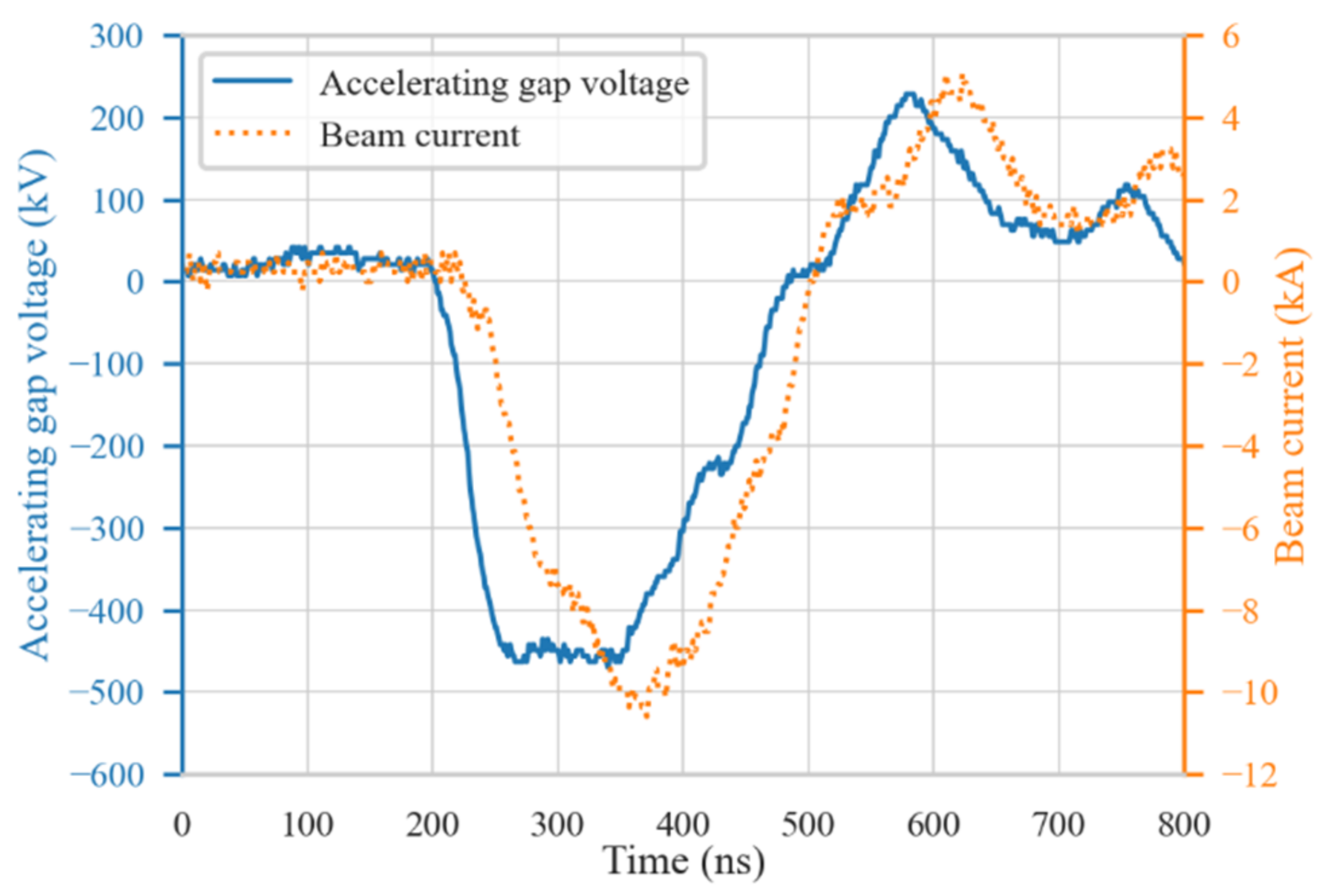
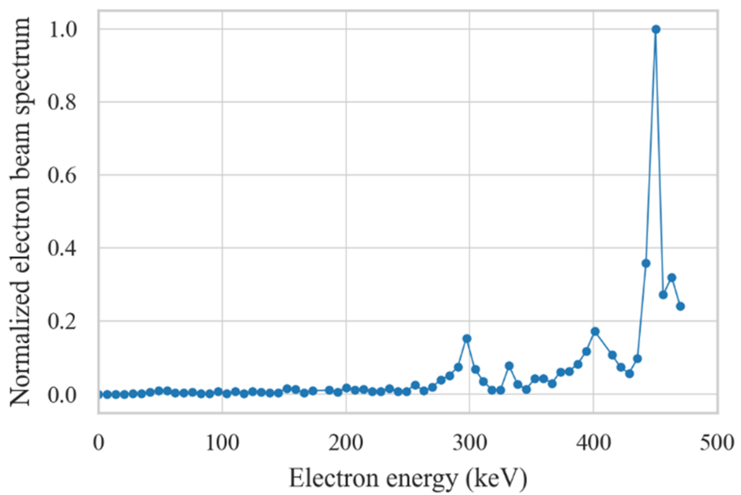
2.1. IPEB Energy Spectrum Analysis

As the MC method used in the particle transportation simulation essentially gives results on each primary electron, to provide a proper estimation of the output X-ray fluence and dose by IPEB, it is necessary to obtain the IPEB spectrum for reasonable MC calculation input. The IPEBs generated on the BIPPAB-450 pulsed particle accelerator [26] were taken for electron spectrum analysis. This facility generates pulsed high voltage with amplitude up to 250 kV with a magneto generator based on a pulsed transformer, and then the pulsed voltage is modulated by a Blumlein transforming line, further multiplied to over 450 kV by a pulsed autotransformer, applied on a graphite cathode of the electron beam diode and triggers micro-explosives via field emission at micro-tips on the surface with a plasma sheath being formed. The electrons in the plasma are accelerated by the electric field formed by the pulsed high voltage, and in this way, a high current of kA order can be obtained. Under certain conditions, the plasma emitter can be regarded as a source with an unlimited electron supply, and the current emission is only confined by the space-charge effect in the accelerating gap. As the emission happens on the cathode surface in an area with a diameter of 3.5 cm, compared with an anode-cathode gap of several mm, the emission current can be simplified into a plane-parallel diode model well described by Child’s law (also widely mentioned as the three halves law) [27]:
J   =   4 ε 0 2 e 9 m e   ·   U 3 / 2 d .
in which J is the current density, ε0 is the vacuum permittivity, e and me are the electron charge and mass, U is the accelerating voltage on the cathode, and d is the width of the anode-cathode gap.
Assuming that the initial kinetic energy of the electrons in the plasma is much lower than after acceleration, i.e., can be taken as zero, and no prominent electron scattering in the anode-cathode gap (corresponding to high vacuum), by applying Child’s law the correspondence between the accelerating voltage and the IPEB energy spectrum can be established. From the acquired working voltage of the IPEB diode (Figure 1), the IPEB spectrum can be deduced (Figure 2). Most of the electrons are distributed around 300 keV and over 370 keV. In the MC simulation, this energy spectrum is normalized to a probability density distribution for the sampling of the source particle. For the total number of electrons in one pulse, the beam current can be approximated as a triangular pulse with a typical peak value of 2.5 kA and full pulse length of 320 ns, and thus the number of electrons in one pulse is 2.5 × 10¹⁵.

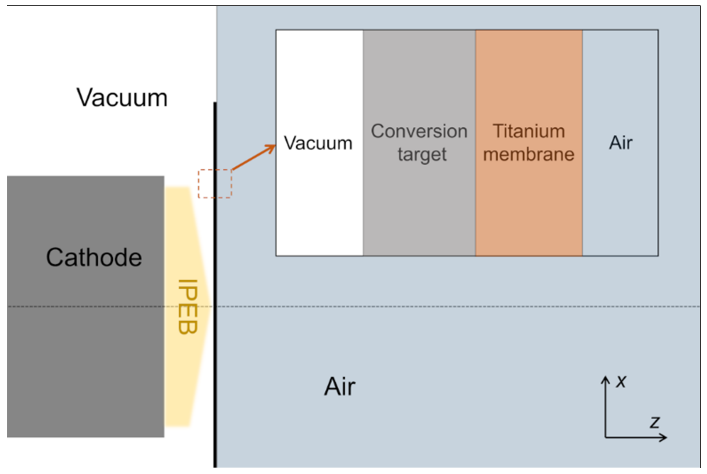
2.2. X-ray Conversion Simulation

For the simulation of electron stopping in matter and photon generation, the Monte Carlo code FLUKA (FLUktuierende KAskade) [28,29] released by the Conseil European pour la Recherche Nucleaire (CERN) was used. First used for electron accelerator shielding, FLUKA has developed into a general-purpose particle transportation simulation software for over 60 particles and is widely used for radiation shielding [30,31,32], dosimetry [33,34], detector design [35,36,37], X-ray generation [38,39,40], and medical physics [28,41]. To deal with bremsstrahlung, the latest version of FLUKA adopts improved Seltzer and Berger differential cross-sections for the transport algorithm on charged particles and photons, and can handle electron and photon transportation with energy down to 1 keV, obtaining good accuracy for primary electrons with a single scattering algorithm. The graphical user interface Flair [42] further enables fast editing of FLUKA input, visualization of geometry, monitoring of program running, post-processing, and demonstration of simulation results, making FLUKA more easy to use compared with other MC programs.
In the MC simulation, the IPEB was simplified as a pencil beam with a radius of 3.5 cm, emitted from z = −1 cm (1 cm of accelerating gap) with the beam center along the z-axis in the positive direction. The energy spectrum of the IPEB was sampled with the distribution in Figure 2 and compiled into the FLUKA simulation via a Fortran script. The targets in the simulation had a radius of 5 cm with their rear surfaces on the xoy plane with the surface center on the point (0, 0, 0). The xoy plane divided the whole space into two parts, with the z < 0 part in the vacuum and the other half in the air, making the rear surface of the target align on the plane of the vacuum-air boundary (Figure 3). The targets were divided into two groups; the first was tungsten and molybdenum targets for the evaluation of X-ray conversion with thicknesses from 0 to CSDA (Continuous Slowing Down Approximation) range estimated with the NIST (National Institute of Standards and Technology) ESTAR database [43]. The CSDA range of tungsten and molybdenum was taken as 155 and 248 μm, taking their density of 19.26 and 10.28 g/cm3, respectively. For the analysis of the combination of a conversion layer (tungsten or molybdenum) and a membrane (titanium) X-ray window, tests were made from the thinnest conversion layer at maximum photon emission with a thick titanium window to the thickest conversion layer with a thinnest titanium window of 50 μm. The use of tungsten was for the verification of the maximum achievable X-ray output, and molybdenum, for its moderate price, also served as a candidate for the X-ray conversion layer. Although beryllium is widely used in X-ray windows, due to its toxicity, the use of beryllium for X-ray windows with a radius of several cm for possible applications such as food and environmental irradiation brings inferiority in safety and maintenance compared with using titanium. For simplicity in modeling, the conversion layer and the titanium window were separated by a plane into a cylinder. As it is complicated to estimate the CSDA range in a two-layer structure with ESTAR, tungsten and molybdenum targets with the thickness of ESTAR CSDA range were tested with FLUKA and the same criteria, i.e., decreasing the electron fluence by seven orders, were adopted to determine dual-layer target thicknesses.
For the tally of the spatial distribution of photon fluence and dose equivalent, considering the model symmetry, the results on the roz plane with a binning resolution of 1 mm in an area of 20 × 40 cm2 were scored. In FLUKA, the dose equivalent was calculated by taking the results from photon fluence and spectrum, with conversion coefficients from ICRP74 [44] and Pelliccioni data [45]. The transmission X-ray energy spectrum after the window within the polar angle of 60° was scored with an energy binning of 1 keV. An energy cut-off of 2 keV in particle generation and transportation was used for photon energy spectrum simulation. The energy deposition in each region in the models was also calculated to evaluate the possible heating by electron energy deposition. A total number of 5 × 10⁸ primary electrons were used in the simulation on each target parameter and the error of simulation was within 2% near the target in photon fluence and energy spectrum estimation. The simulation was carried out on two servers with AMD Ryzen 2700 CPU with 16 GB DDR4 2666 MHz RAM, running the Ubuntu 20.04.3 operating system with FLUKA 4-2.0 and Flair 3.1-14.

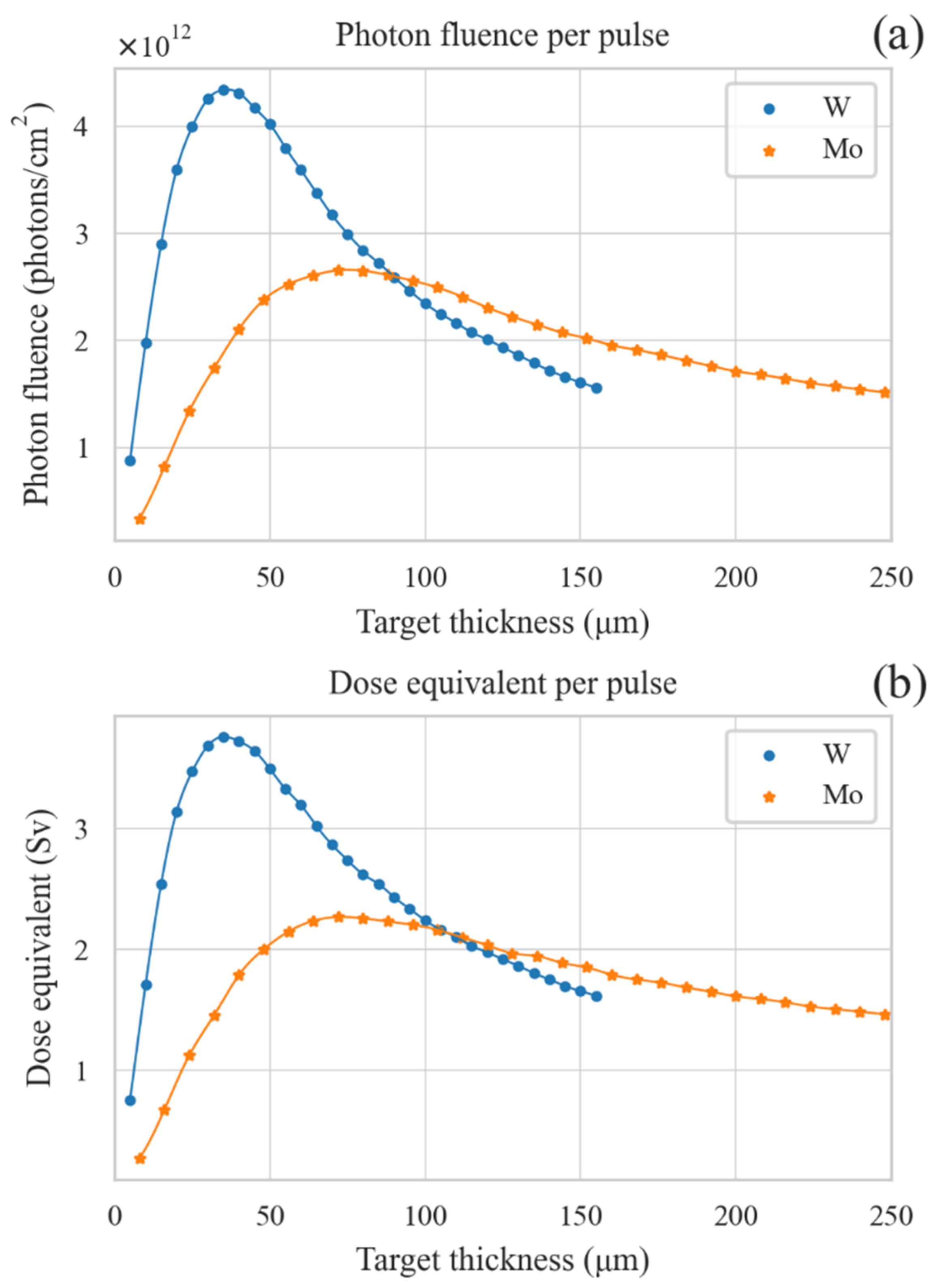
3. Results and Discussion

In the simulation with tungsten and molybdenum targets, to compare the photon emission from the target, the photon fluence and dose equivalent in the center of the rear target surface were taken for analysis (Figure 4). Taking tungsten as the target material, the peak photon fluence and dose equivalent increased by over 70% compared with molybdenum. A similar trend in photon fluence and dose equivalent was exhibited with the change in the target thickness; at thin target thicknesses, the photon fluence and dose equivalent was low and rose significantly with the increase in the target thickness. In this stage, the conversion of X-ray was predominantly limited by the insufficient electron stopping in the target. With further increased target thicknesses, the photon fluence reached a maximum value and the thickness at this maximum photon emission, about 35 μm for tungsten and 72 μm for molybdenum, was much smaller than the CSDA range of the electrons in the target (approximately 22.6% and 28.2% of the CSDA range in tungsten and molybdenum). When the target thickness exceeded this optimal value, the output photon fluence and dose equivalent started to decrease, but in a slow trend as there existed both X-ray emission due to the stopping of electrons in the target and X-ray absorption by the extra thickness which exceeded the optimal thicknesses. When the target thickness reached the CSDA range, the photon fluences and dose equivalent decreased by over 50% in tungsten and about 40% for molybdenum compared with the fluence at optimal target thicknesses. This means that a sacrifice in the X-ray output is made for complete electron stopping, and with a higher target atomic number comes higher output loss. This can be explained as when electrons reach the depth over the optimal thickness, a significant portion of their energy has already been deposited, as the stopping power of sub-MeV electrons reaches the maximum value soon after entering the target. At the thick region of the target, the photon emission is generally weaker than the photon absorption.
In the spatial distribution of photon fluence and dose equivalent in the roz plane (Figure 5 and Figure 6 and Figures S1 and S2 in Supplementary Materials), in addition to the photon generation by molybdenum being weaker than with tungsten, the photon distribution and its evolution trend versus the target thickness was similar on the two target materials. At a thin target thickness, the photon emission in the transmission direction was much stronger than in the reflection direction. The photon emission increased drastically with increased target thicknesses, both in the transmission and reflection directions. At the optimal thickness, the photon emission distribution in the two directions was quite close, slightly stronger in the transmission direction. With further increased target thicknesses, the photon emission in the reflection direction did not change significantly, but the transmission photons exhibited apparent attenuation due to absorption by the target. The photon fluence had a higher value at a smaller polar angle and decreased sharply approaching the xoy plane. This was induced by the angular distribution of photon emission and higher photon absorption by larger mass thickness in the polar angle near 90°.
In the lateral distribution of dose-equivalent distribution at full electron stopping (Figure 7 and Figure S3 in Supplementary Materials), in the region within 1 cm behind the target, an output of over 1 Sv per pulse could be achieved near the target center and decreased sharply at radii over 3 cm. At farther positions from the target, the output declined rapidly; at the region 4–5 cm away from the target, the dose equivalent decreased by over 70% and further decreased by 90% on the plane 10 cm from the target. However, at these positions, the lateral uniformity of the dose equivalent became better at a larger radius. In the transmission photon spectrum (Figure 8), at smaller polar angles existed stronger X-ray emission, and at larger polar angles, low energy photon exhibited higher attenuation. The photon energy was mainly within 200 keV and with a tungsten target, due to characteristic absorption at 67.59 keV, a significant portion of the photons came with energies below this value. There was no apparent characteristic emission and absorption in molybdenum above 17.44 keV, the main part of the photon spectrum distribution from the molybdenum target being relatively smooth.
Based on the above analysis, when the conversion target thickness exceeds the optimal value, the self-absorption of the target itself is a primary factor that limits the output. Several dual-layer targets with full electron stopping were tested with the titanium window. In the target thickness parameters (Table 1 and Table 2), the combinations took the optimal conversion layer thickness (also the thinnest) with a thick titanium window to the other end of the thinnest possible titanium window (50 μm) with a relatively thick conversion layer, and some parameters in between.
The spatial distribution of photon fluence and dose equivalent after the dual-layer target (Figure 9 and Figure 10 and Figures S4 and S5 in Supplementary Materials) in general was similar to that of thick mono-material targets; the photon output in the transmission direction was weaker than in the reflection direction. By comparison of the output in the center after the titanium window surface (Table 3 and Table 4), the combination with the thinnest conversion l and thick titanium window achieved the highest photon output and was about 150% the level of the combination of a thick conversion target and thin titanium window. In lateral distribution (Figure 11 and Figure S6 in Supplementary Materials), compared with the mono-material target, the tungsten composite target achieved a significant increase of over 80%, while for molybdenum, the increase was about 27% in the region within 1 cm behind the target. When using the dual-layer conversion target in the region near the target system, the output was much higher in a smaller radius or at farther distances from the target with a lower output level in a larger radius with better lateral uniformity. In the photon spectrum (Figure 12), with a thicker conversion target and thin titanium window, stronger photon attenuation existed than with a thin conversion layer target with 50% less in the total photon counts, especially in low energy photons.
By the above analysis, the combination of a thin conversion target at optimal photon emission thickness and a thick titanium window is an optimized choice for maximum X-ray output. When considering more issues, such as target heating by IPEBs, some problems in the actual design need to be solved. The optimal conversion target is relatively thin under the thermal shocks by IPEBs. It is verified by experimental and numerical means that under the irradiation of IPEBs, a temperature rise of several tens of K [26] can be induced in the target and the consequent thermal stress is an important cause of target damage. The situation of conversion layer damage can be monitored by online monitoring, such as with a semiconductor X-ray detector [46], and in tests with a titanium electron window, a window with a thickness within 100 μm can well secure the vacuum in the vacuum chamber [23], ensuring that, with the dual-layer target, the working vacuum can be kept even after conversion layer damage. However, frequent maintenance of the window system should undoubtedly be avoided in practical applications. In this sense, the use of a thicker conversion layer may be better for higher system reliability in long-term operation. Further, with a thicker target, such as with 80 μm tungsten and 137 μm molybdenum, the energy deposition in the titanium window (Figure 13 and Figure S7 in Supplementary Materials) is over two orders lower than in the conversion layer and the titanium window heating by IPEBs is negligible, while with a thin conversion layer at the optimized conversion layer thicknesses, the titanium window may endure heating at high IPEB output repetition and extra cooling may be required.

4. Conclusions

The design and output optimization of transmission X-ray conversion targets was analyzed. The spectrum of an intense pulsed electron beam emitted via explosive diode with a peak value of 470 keV was taken as the source, and it was found by FLUKA Monte Carlo simulation via analysis of photon fluence and dose equivalent distribution that a tungsten and molybdenum target with the thickness of 35 and 72 μm achieved the highest output X-ray fluence and dose equivalent. It was further proved that these optimized conversion layer thickness, combined with proper titanium window thickness for total electron stopping, produced higher X-ray output than with thicker conversion layers. When used with an electron beam with a 3.5 cm radius, 470 keV peak electron energy, and 5 kA beam current, this conversion system could achieve an X-ray output of over 1 Sv per pulse behind the target. The spatial distribution of photon distribution revealed that the X-ray output attenuates drastically at larger distances from the target, with better lateral uniformity and a wider radiation range. Based on this, the radiation of samples can be arranged for expected dosage and further tailoring of the radiation field, such as achieving better uniformity with a flattening filter, can also be carried out based on this work.

Supplementary Materials

The following supporting information can be downloaded at: https://www.mdpi.com/article/10.3390/app12094327/s1, Figure S1: Spatial distribution of photon fluence by per IPEB pulse on molybdenum target; Figure S2: Spatial distribution of dose equivalent by per IPEB pulse on tungsten target; Figure S3: Dose equivalent distribution per IPEB pulse on molybdenum target with the thickness of CSDA range; Figure S4: Spatial distribution of photon fluence by IPEB on molybdenum-titanium dual-layer target; Figure S5: Spatial distribution of dose equivalent by IPEB on molybdenum-titanium dual-layer target; Figure S6: Dose equivalent distribution per IPEB pulse on dual-layer targets with parameters of Table 4; Figure S7: Electron energy deposition in different regions with parameters in Table 2.

Author Contributions

Conceptualization, X.Y. and I.S.E.; methodology, X.Y.; writing—original draft preparation, X.Y.; writing—review and editing, I.S.E. and S.Z.; software, X.Y., S.Z. and J.Z.; validation, C.X. and C.T.; supervision, S.Y. and X.L.; resources, G.E.R. and X.L. All authors have read and agreed to the published version of the manuscript.

Funding

This research was funded by National Natural Science Foundation of China by Contract No. 11875084 and 12075024.

Institutional Review Board Statement

Ethics approval was not required for this study.

Informed Consent Statement

Not applicable.

Acknowledgments

Xiao Yu would like to express gratitude to his friends, Mohan Li, Tianchen Sun and Jiajun Yu for their warm support during this research.

Conflicts of Interest

The authors declare no conflict of interest.

References

  1. Röntgen, W.C. On a new kind of rays. Science 1896, 3, 227–231. [Google Scholar] [CrossRef] [PubMed]
  2. Behling, R. Medical X-ray sources now and for the future. Nucl. Instrum. Methods Phys. Res. Sect. A Accel. Spectrometers Detect. Assoc. Equip. 2017, 873, 43–50. [Google Scholar] [CrossRef]
  3. Behling, R. Modern Diagnostic X-Ray Sources: Technology, Manufacturing, Reliability; CRC Press: Boca Raton, FL, USA, 2015; ISBN 9781482241334. [Google Scholar]
  4. Hanawalt, J.D.; Rinn, H.W.; Frevel, L.K. Chemical Analysis by X-ray Diffraction. Ind. Eng. Chem. Anal. Ed. 1938, 10, 457–512. [Google Scholar] [CrossRef]
  5. Baruchel, J.; Buffière, J.Y.; Maire, E.; Merle, P.; Peix, G. X-ray tomography in material science. Hermes Sci. Publ. 2000, 31, 1–209. [Google Scholar]
  6. Hanke, R.; Fuchs, T.; Uhlmann, N. X-ray based methods for non-destructive testing and material characterization. Nucl. Instrum. Methods Phys. Res. Sect. A Accel. Spectrometers Detect. Assoc. Equip. 2008, 591, 14–18. [Google Scholar] [CrossRef]
  7. Jenkins, R. X-ray Techniques: Overview. In Encyclopedia of Analytical Chemistry: Applications, Theory and Instrumentation; John Wiley & Sons, Ltd.: Hoboken, NJ, USA, 2006; ISBN 9780471976707. [Google Scholar] [CrossRef]
  8. Zentai, G. X-ray imaging for homeland security. Int. J. Signal Imaging Syst. Eng. 2010, 3, 13–20. [Google Scholar] [CrossRef]
  9. Chakhlov, S.V.; Kasyanov, S.V.; Kasyanov, V.A.; Osipov, S.P.; Stein, M.M.; Stein, A.M.; Xiaoming, S. Betatron application in mobile and relocatable inspection systems for freight transport control. J. Physics Conf. Ser. 2016, 671, 12024. [Google Scholar] [CrossRef] [Green Version]
  10. Tang, C.; Chen, H.; Liu, Y.; Wang, X. Low-energy linacs and their applications in tsinghua university. In Proceedings of the 23rd International Linear Accelerator Conference, LINAC 2006, Knoxville, TN, USA, 21–25 August 2006; pp. 256–258. [Google Scholar]
  11. Bartscher, M.; Hilpert, U.; Goebbels, J.; Weidemann, G. Enhancement and Proof of Accuracy of Industrial Computed Tomography (CT) Measurements. CIRP Ann. Manuf. Technol. 2007, 56, 495–498. [Google Scholar] [CrossRef]
  12. du Plessis, A.; le Roux, S.G.; Guelpa, A. Comparison of medical and industrial X-ray computed tomography for non-destructive testing. Case Stud. Nondestruct. Test. Eval. 2016, 6, 17–25. [Google Scholar] [CrossRef] [Green Version]
  13. Edwards, D.A.; Syphers, M.J. An introduction to the physics of particle accelerators. AIP Conf. Proc. 2008, 184, 2–189. [Google Scholar] [CrossRef]
  14. Tajima, T.; Dawson, J.M. Laser electron accelerator. Phys. Rev. Lett. 1979, 43, 267–270. [Google Scholar] [CrossRef] [Green Version]
  15. Faure, J.; Glinec, Y.; Pukhov, A.; Klselev, S.; Gordienko, S.; Lefebvre, E.; Rousseau, J.P.; Burgy, F.; Malka, V. A laser-plasma accelerator producing monoenergetic electron beams. Nature 2004, 431, 541–544. [Google Scholar] [CrossRef] [PubMed]
  16. Egorov, I.S.; Kaikanov, M.I.; Lukonin, E.I.; Remnev, G.E.; Stepanov, A.V. The Astra repetitive-pulse electron accelerator. Instrum. Exp. Technol. 2013, 56, 568–570. [Google Scholar] [CrossRef]
  17. Nashilevskiy, A.; Egorov, I.; Ponomarev, D.; Ezhov, V.; Kholodnaya, G.; Remnev, G. A high repetition rate electron accelerator with a water Blumlein and a matching transformer. Nucl. Instrum. Methods Phys. Res. Sect. A Accel. Spectrometers Detect. Assoc. Equip. 2020, 959, 163565. [Google Scholar] [CrossRef]
  18. Sazonov, R.; Kholodnaya, G.; Ponomarev, D.; Lapteva, O.; Konusov, F.; Gadirov, R.; Zhirkov, I. Pulsed plasma chemical synthesis of TiO2@TixCyOz nanocomposite. Fullerenes Nanotub. Carbon Nanostruct. 2021, 29, 567–575. [Google Scholar] [CrossRef]
  19. Siwek, M.; Edgecock, T. Application of electron beam water radiolysis for sewage sludge treatment—A review. Environ. Sci. Pollut. Res. 2020, 27, 42424–42448. [Google Scholar] [CrossRef]
  20. Kholodnaya, G.; Egorov, I.; Sazonov, R.; Serebrennikov, M.; Poloskov, A.; Ponomarev, D.; Zhirkov, I. Study of the conditions for the effective initiation of plasma-chemical treatment of flue gas under the influence of a pulsed electron beam. Laser Part. Beams 2020, 38, 197–203. [Google Scholar] [CrossRef]
  21. Isemberlinova, A.A.; Egorov, I.S.; Nuzhnyh, S.A.; Poloskov, A.V.; Pokrovskaya, E.A.; Vertinskiy, A.V.; Konusov, F.V.; Sukhikh, E.S.; Chubik, M.V.; Remnev, G.E. The pulsed X-ray treatment of wheat against pathogenic fungi. Nucl. Instrum. Methods Phys. Res. Sect. B Beam Interact. Mater. Atoms 2021, 503, 75–78. [Google Scholar] [CrossRef]
  22. Kudryavtseva, V.L.; Bolbasov, E.N.; Ponomarev, D.V.; Remnev, G.E.; Tverdokhlebov, S.I. The Influence of Pulsed Electron Beam Treatment on Properties of PLLA Nonwoven Materials Produced by Solution Blow Spinning. Bionanoscience 2018, 8, 131–139. [Google Scholar] [CrossRef]
  23. Egorov, I.; Yu, X.; Poloskov, A.; Serebrennikov, M.; Le, X.; Remnev, G. Bremsstrahlung converter system with target in vacuum. Vacuum 2021, 187, 110149. [Google Scholar] [CrossRef]
  24. Egorov, I.; Poloskov, A.; Serebrennikov, M.; Remnev, G. Self-bearing membrane exit window with the separate anode for sub-microsecond electron accelerator: Exit window for sub-microsecond e-accelerator. Vacuum 2020, 173, 109111. [Google Scholar] [CrossRef]
  25. Yu, X.; Shen, J.; Zhang, S.; Zhang, J.; Zhang, N.; Egorov, I.S.; Yan, S.; Tan, C.; Remnev, G.E.; Le, X. Numerical optimization of transmission bremsstrahlung target for intense pulsed electron beam. Nucl. Eng. Technol. 2022, 54, 666–673. [Google Scholar] [CrossRef]
  26. Yu, X.; Shen, J.; Qu, M.; Liu, W.; Zhong, H.; Zhang, J.; Yan, S.; Zhang, G.; Le, X. Infrared imaging diagnostics for intense pulsed electron beam. Rev. Sci. Instrum. 2015, 86, 83305. [Google Scholar] [CrossRef] [PubMed]
  27. Langmuir, I. The effect of space charge and residual gases on thermionic currents in high vacuum. Phys. Rev. 1913, 2, 450–486. [Google Scholar] [CrossRef]
  28. Böhlen, T.T.; Cerutti, F.; Chin, M.P.W.; Fassò, A.; Ferrari, A.; Ortega, P.G.; Mairani, A.; Sala, P.R.; Smirnov, G.; Vlachoudis, V. The FLUKA Code: Developments and challenges for high energy and medical applications. Nucl. Data Sheets 2014, 120, 211–214. [Google Scholar] [CrossRef] [Green Version]
  29. Battistoni, G.; Boehlen, T.; Cerutti, F.; Chin, P.W.; Esposito, L.S.; Fassò, A.; Ferrari, A.; Lechner, A.; Empl, A.; Mairani, A.; et al. Overview of the FLUKA code. Ann. Nucl. Energy 2015, 82, 10–18. [Google Scholar] [CrossRef] [Green Version]
  30. Lakshminarayana, G.; Kumar, A.; Tekin, H.O.; Issa, S.A.M.; Al-Buriahi, M.S.; Dong, M.G.; Lee, D.E.; Yoon, J.; Park, T. In-depth survey of nuclear radiation attenuation efficacies for high density bismuth lead borate glass system. Results Phys. 2021, 23, 104030. [Google Scholar] [CrossRef]
  31. Mostafa, A.M.A.; Issa, S.A.M.; Zakaly, H.M.H.; Zaid, M.H.M.; Tekin, H.O.; Matori, K.A.; Sidek, H.A.A.; Elsaman, R. The influence of heavy elements on the ionizing radiation shielding efficiency and elastic properties of some tellurite glasses: Theoretical investigation. Results Phys. 2020, 19, 103496. [Google Scholar] [CrossRef]
  32. El-Denglawey, A.; Zakaly, H.M.H.; Alshammari, K.; Issa, S.A.M.; Tekin, H.O.; AbuShanab, W.S.; Saddeek, Y.B. Prediction of mechanical and radiation parameters of glasses with high Bi2O3 concentration. Results Phys. 2021, 21, 103839. [Google Scholar] [CrossRef]
  33. Botta, F.; Mairani, A.; Battistoni, G.; Cremonesi, M.; Di Dia, A.; Fassò, A.; Ferrari, A.; Ferrari, M.; Paganelli, G.; Pedroli, G.; et al. Calculation of electron and isotopes dose point kernels with fluka Monte Carlo code for dosimetry in nuclear medicine therapy. Med. Phys. 2011, 38, 3944–3954. [Google Scholar] [CrossRef]
  34. Kirby, D.; Green, S.; Fiorini, F.; Parker, D.; Romagnani, L.; Doria, D.; Kar, S.; Lewis, C.; Borghesi, M.; Palmans, H. Radiochromic film spectroscopy of laser-accelerated proton beams using the FLUKA code and dosimetry traceable to primary standards. Laser Part. Beams 2011, 29, 231–239. [Google Scholar] [CrossRef]
  35. Guthoff, M.; De Boer, W.; Müller, S. Simulation of beam induced lattice defects of diamond detectors using FLUKA. Nucl. Instrum. Methods Phys. Res. Sect. A Accel. Spectrometers Detect. Assoc. Equip. 2014, 735, 223–228. [Google Scholar] [CrossRef]
  36. Fassò, A.; Ferrari, A.; Ranft, J.; Sala, P.R.; Stevenson, G.R.; Zazula, J.M. A comparison of FLUKA simulations with measurements of fluence and dose in calorimeter structures. Nucl. Inst. Methods Phys. Res. A 1993, 332, 459–468. [Google Scholar] [CrossRef] [Green Version]
  37. Akkurt, İ.; Waheed, F.; Akyildirim, H.; Gunoglu, K. Monte Carlo simulation of a NaI(Tl) detector efficiency. Radiat. Phys. Chem. 2020, 176, 109081. [Google Scholar] [CrossRef]
  38. Liu, J.; Han, L.; Zhao, W.; Ma, Y.; Niu, G. Design and fabrication of a new tungsten-diamond transmission target for micro-computed tomography. In Proceedings of the 9th International Symposium on Advanced Optical Manufacturing and Testing Technologies: Micro-and Nano-Optics, Catenary Optics, and Subwavelength Electromagnetics, Chengdu, China, 26–29 June 2018; International Society for Optics and Photonics: Bellingham, WA, USA, 2019. [Google Scholar]
  39. Wang, S.F.; Chiang, H.Y.; Liao, Y.J.; Liu, R.S.; Cheng, C.C.; Yang, H.W.; Wang, S.W.; Lin, Y.C.; Hsu, S.M. Respective radiation output characteristics of transmission-target and reflection-target X-ray tubes with the same beam quality. Radiat. Phys. Chem. 2019, 158, 188–193. [Google Scholar] [CrossRef]
  40. Nasseri, M.M. Determination of Tungsten Target Parameters for Transmission X-ray Tube: A Simulation Study Using Geant4. Nucl. Eng. Technol. 2016, 48, 795–798. [Google Scholar] [CrossRef] [Green Version]
  41. Battistoni, G.; Bauer, J.; Boehlen, T.T.; Cerutti, F.; Chin, M.P.W.; Dos Santos Augusto, R.; Ferrari, A.; Ortega, P.G.; Kozlowska, W.; Magro, G.; et al. The FLUKA code: An accurate simulation tool for particle therapy. Front. Oncol. 2016, 6, 116. [Google Scholar] [CrossRef] [Green Version]
  42. Vlachoudis, V. Flair: A powerful but user friendly graphical interface for FLUKA. In Proceedings of the International Conference on Mathematics, Computational Methods and Reactor Physics 2009, Saragota Springs, NY, USA, 3–7 May 2009; American Nuclear Society: La Grange Park, IL, USA, 2009; Volume 2, pp. 790–800. [Google Scholar]
  43. Berger, M.J.; Coursey, J.S.; Zucker, M.A.; Chang, J. Stopping-Power & Range Tables for Electrons, Protons, and Helium Ions. NISTIR 2017, 4999, 1–17. [Google Scholar] [CrossRef]
  44. ICRP International Commission on Radiological Protection. Conversion coefficients for use in radiological protection against external radiation. Ann. ICRP 1996, 26, 1–205. [Google Scholar]
  45. Pelliccioni, M. Overview of fluence-to-effective dose and fluence-to-ambient dose equivalent conversion coefficients for high energy radiation calculated using the fluka code. Radiat. Prot. Dosim. 2000, 88, 279–297. [Google Scholar] [CrossRef]
  46. Egorov, I.; Xiao, Y.; Poloskov, A. PIN-diode diagnostics of pulsed electron beam for high repetition rate mode. J. Phys. Conf. Ser. 2017, 830, 12044. [Google Scholar] [CrossRef] [Green Version]
Figure 1. Typical oscilloscope curves of the accelerating gap voltage and beam current of the IPEB diode.
Applsci 12 04327 g001
Figure 2. The normalized energy spectrum of the IPEBs deduced from the diode input voltage.
Applsci 12 04327 g002
Figure 3. Schematic drawing of the dual-layer target model.
Applsci 12 04327 g003
Figure 4. (a) Transmission photon fluence and (b) dose equivalent per IPEB pulse with energy spectrum in Figure 2 from tungsten and molybdenum conversion targets versus the target thickness.
Applsci 12 04327 g004
Figure 5. Spatial distribution of photon fluence by per IPEB pulse on tungsten target with thickness of (a) 5 μm, (b) 35 μm (the optimal target thickness), (c) 70 μm (2 times of the optimal target thickness), (d) 155 μm (CSDA range).
Applsci 12 04327 g005
Figure 6. Spatial distribution of dose equivalent by per IPEB pulse on tungsten target with thickness of (a) 5 μm, (b) 35 μm (the optimal target thickness), (c) 70 μm (2 times of the optimal target thickness), (d) 155 μm (CSDA range).
Applsci 12 04327 g006
Figure 7. Dose equivalent distribution per IPEB pulse on tungsten target with the thickness of CSDA range.
Applsci 12 04327 g007
Figure 8. Transmission X-ray spectrum per IPEB primary electron on (a) tungsten and (b) molybdenum target with the thickness of CSDA range.
Applsci 12 04327 g008
Figure 9. Spatial distribution of photon fluence by IPEB on tungsten-titanium dual-layer target with thicknesses combination (subfigure (ae) corresponding to the duplicate item titles in Table 1).
Applsci 12 04327 g009
Figure 10. Spatial distribution of dose equivalent by IPEB on tungsten-titanium dual-layer target with thicknesses combination (subfigure (ae) corresponding to the duplicate item titles in Table 1).
Applsci 12 04327 g010
Figure 11. Dose equivalent distribution per IPEB pulse on dual-layer targets with parameters of Table 3.
Applsci 12 04327 g011
Figure 12. Transmission photons spectrum by per IPEB electron on tungsten-titanium and molybdenum-titanium dual-layer targets with parameters in (a) Table 1 and (b) Table 2.
Applsci 12 04327 g012
Figure 13. Electron energy deposition in different regions with different target parameter combinations, (a) 115 μm W with 50 μm Ti, (b) 105 μm W with 100 μm Ti, (c) 80 μm W with 200 μm Ti, (d) 55 μm W with 300 μm Ti, (e) 35 μm W with 360 μm Ti.
Applsci 12 04327 g013
Table 1. The thickness of the tungsten-titanium target (in μm) with mass densities of 19.26 and 4.54 g/cm3 correspondingly.
abcde
W115105805535
Ti50100200300360
Table 2. The thickness of the molybdenum-titanium target (in μm) with mass densities of 10.22 and 4.54 g/cm3 correspondingly.
abcde
Mo2051801379072
Ti50100200300340
Table 3. Photo fluence after the dual-layer target per pulse (in 1012 photons/cm2) with target parameters in Table 1 and Table 2.
abcde
W + Ti2.0232.1702.6633.2983.727
Mo + Ti1.6531.7411.9572.2592.367
Table 4. Dose equivalent after the dual-layer target per pulse (in Sv) with target parameters in Table 1 and Table 2.
abcde
W + Ti1.9872.1122.4912.9263.240
Mo + Ti1.5601.6701.7491.9241.984
Publisher’s Note: MDPI stays neutral with regard to jurisdictional claims in published maps and institutional affiliations.

